

Page 1
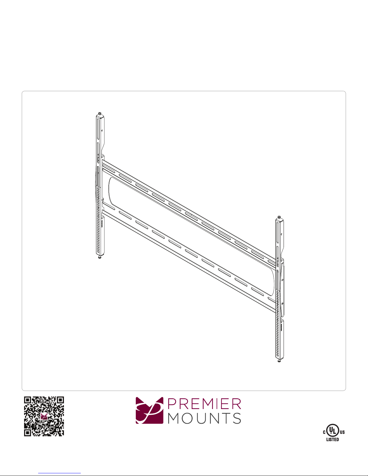
P5080F
Installation Guide
Low-Prole Mount for Flat-Panels
www.mounts.com | North America 800.368.9700 | International +1-714-632-7100
1321 S. State College Blvd., Fuller ton, CA 92831 USA
Page 2
Weight Limit
Maximum Flat Panel Weight:
300 lbs.
THE WALL STRUCTURE MUST BE CAPABLE OF SUPPORTING AT
LEAST FOUR TIMES THE WEIGHT OF THE FLAT PANEL. IF NOT, THE
WALL STRUCTURE MUST BE REINFORCED.
Warning Statements
PRIOR TO THE INSTALLATION OF THIS PRODUCT, THE INSTALLATION INSTRUCTIONS MUST BE READ AND COMPLETELY
UNDERSTOOD. KEEP THESE INSTALLATION INSTRUCTIONS IN AN EASILY ACCESSIBLE LOCATION FOR FUTURE REFERENCE.
PROPER INSTALLATION PROCEDURE BY A QUALIFIED SERVICE TECHNICIAN MUST BE FOLLOWED, AS OUTLINED IN THESE
INSTALLATION INSTRUCTIONS. FAILURE TO DO SO COULD RESULT IN PROPERTY DAMAGE, SERIOUS PERSONAL INJURY, OR
EVEN DEATH.
SAFETY MEASURES MUST BE PRACTICED AT ALL TIMES DURING THE ASSEMBLY OF THIS PRODUCT. USE PROPER SAFETY
EQUIPMENT AND TOOLS FOR THE ASSEMBLY PROCEDURE TO PREVENT PERSONAL INJURY.
PREMIER MOUNTS DOES NOT WARRANT AGAINST DAMAGE CAUSED BY THE USE OF ANY PREMIER MOUNTS PRODUCT FOR
PURPOSES OTHER THAN THOSE FOR WHICH IT WAS DESIGNED OR DAMAGE CAUSED BY UNAUTHORIZED ATTACHMENTS OR
MODIFICATIONS, AND IS NOT RESPONSIBLE FOR ANY DAMAGES, CLAIMS, DEMANDS, SUITS, ACTIONS OR CAUSES OF ACTION
OF WHATEVER KIND RESULTING FROM, ARISING OUT OF OR IN ANY MANNER RELATING TO ANY SUCH USE, ATTACHMENTS OR
MODIFICATIONS.
At least two qualied people should perform the assembly procedure. Personal injury and/or property damage can result from dropping or
mishandling the at panel.
If mounting to wall studs or ceiling studs, make sure that the mounting screws are anchored into the center of the wall studs or ceiling studs.
Use of an edge-to-edge stud nder is recommended.
It is recommended that a maximum of ⅝˝ plaster board be used when mounting to wooden studs.
Be aware of the mounting environment. If drilling and/or cutting into the mounting surface, always make sure that there
are no electrical wires in wall. Cutting or drilling into an electrical line may cause serious personal injury.
Make sure there are no water or natural gas lines inside the wall where the mount is to be located. Cutting or drilling into a water or gas line
may cause severe property damage or personal injury.
This product is intended for indoor use only. Use of this product outdoors could lead to product failure and/or serious personal injury.
Do not install near sources of high heat. Do not install on a structure that is prone to vibration, movement or chance of impact.
AVERTISSEMENT
AVANT L’INSTALLATION DE CE PRODUIT, LES CONSIGNES D’INSTALLATION DOIVENT ÊTRE LUES ET PLEINEMENT COMPRISES.
CONSERVER CES CONSIGNES D’INSTALLATION DANS UN ENDROIT FACILEMENT ACCESSIBLE POUR RÉFÉRENCE FUTURE.
LA PROCÉDURE D’INSTALLATION CORRECTE PAR UN TECHNICIEN QUALIFIÉ DOIT ÊTRE OBSERVÉE, COMME DÉCRIT DANS
CES CONSIGNES D’INSTALLATION. FAUTE DE QUOI DES DOMMAGES MATÉRIELS, BLESSURES GRAVES, VOIRE MÊME LA MORT
PEUT SUBVENIR.
DES MESURES DE SÉCURITÉ DOIVENT ÊTRE PRATIQUÉES À TOUT MOMENT DURANT L’ASSEMBLAGE DE CE PRODUIT.
UTILISER L’ÉQUIPEMENT ET OUTILS DE SÉCURITÉ APPROPRIÉ POUR LA PROCÉDURE D’ASSEMBLAGE AFIN D’ÉVITER DES
BLESSURES.
LES SUPPORTS PREMIER MOUNTS NE GARANTISSENT PAS CONTRE LES DOMMAGES CAUSÉS PAR L’USAGE DU PRODUIT
DE MONTAGE PREMIER MOUNTS À D’AUTRES FINS QUE CELLES POUR LESQUELLES IL A ÉTÉ CONÇU OU DES DOMMAGES
CAUSÉS PAR DES ACCESSOIRES OU DES MODIFICATIONS NON AUTORISÉS, ET NOUS NE POUVONS PAS ÊTRE TENUS
RESPONSABLES DES DOMMAGES, PLAINTES, RÉCLAMATIONS, POURSUITES, ACTIONS OU CAUSES D’ACTION DE N’IMPORTE
QUELLE MANIÈRE RÉSULTANT DE, DÉCOULANT DE OU TOUCHANT DE N’IMPORTE QUELLE MANIÈRE UN TEL USAGE,
ACCESSOIRE OU MODIFICATION
Au moins deux personnes qualiées devraient exécuter la procédure d’assemblage. Il pourrait subvenir des blessures et/ou des dommages
matériels dû à la chute ou à la manipulation incorrecte de l’écran plat.
Si le montage s’effectue sur des rivets, assurez-vous que les vis de montage sont ancrées au centre des rivets. L’usage d’un détecteur de
rivet bord-à-bord est recommandé.
Il est recommandé qu’un maximum de plaque-plâtre de 5/8" soit utilisé lors d’un montage sur des rivets à bois.
Familiarisez-vous avec l’environnement de montage. Si un perçage et/ou une coupe est opéré sur la surface de montage, assurez-vous
toujours qu’il n’y a pas de ls électriques dans le mur. Couper/percer dans une installation électrique peut causer des blessures graves.
S’assurer qu’il n’y a pas de canalisation d’eau ou de gaz naturel dans le mur où le montage doit être localisé. Une coupe ou un perçage
dans une canalisation d’eau ou de gaz naturel peut causer des dommages matériels ou des blessures graves.
Ce produit n’est destiné qu’à être utilisé à l’intérieur. L’utilisation de ce produit à l’extérieur pourrait entraîner des défauts matériels et/ou des
blessures graves.
Ne pas installer près de sources de forte chaleur. Ne pas installer sur une structure soumise aux vibrations, aux mouvements ou aux chocs.
Page 2
Page 3
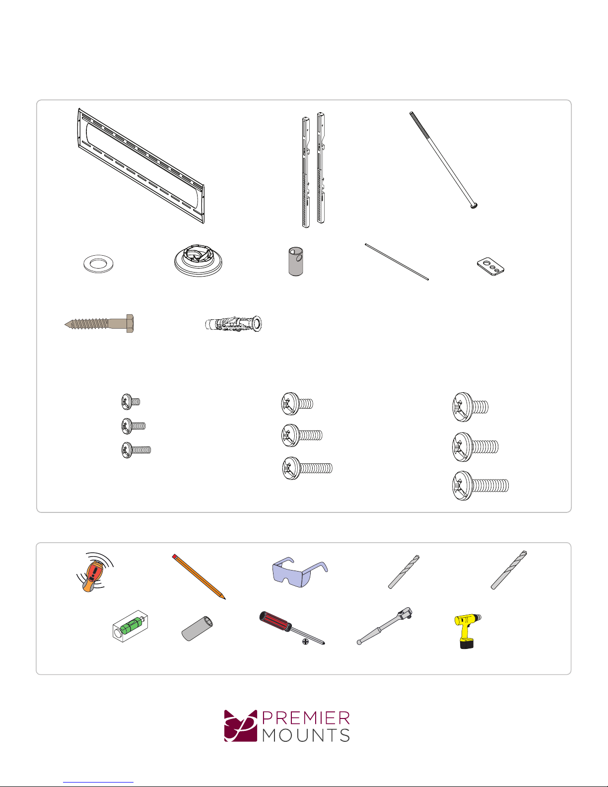
Included Components
P5080F
Installation Guide
5/16” Flat Washers
(Qty 6)
5/16” x 3” Lag Bolts
(Qty 6)
M4 x 12mm (Qty 4)
M4 x 16mm (Qty 4)
M4 x 25mm (Qty 4)
Wall Mount
(Qty 1)
Universal Spacers
(Qty 8)
Finned Anchor
(Qty 6)
Bracket
(Qty 2)
Lock-it Barrel
(Qty 1)
M6 x 12mm (Qty 4)
M6 x 16mm (Qty 4)
Thread Depth Indicator
(Qty 1)
M8 x 12mm (Qty 4)
M8 x 16mm (Qty 4)
M6 x 250 mm
(Qty 4)
Universal Washers
(Qty 4)
M6 x 25mm (Qty 4)
Required for installation
Electronic Stud Finder M6 or 1/4” Drill Bit
Pencil Protective Eyewear
13mm or 1/2” SocketLevel
www.mounts.com | North America 800.368.9700 | International +1-714-632-7100
Phillips Head Screwdriver
Socket Wrench
M8 x 25mm (Qty 4)
3/8” Masonry Drill Bit
Portable Drill
Page 3
Page 4
P5080F
Installation Guide
Introduction
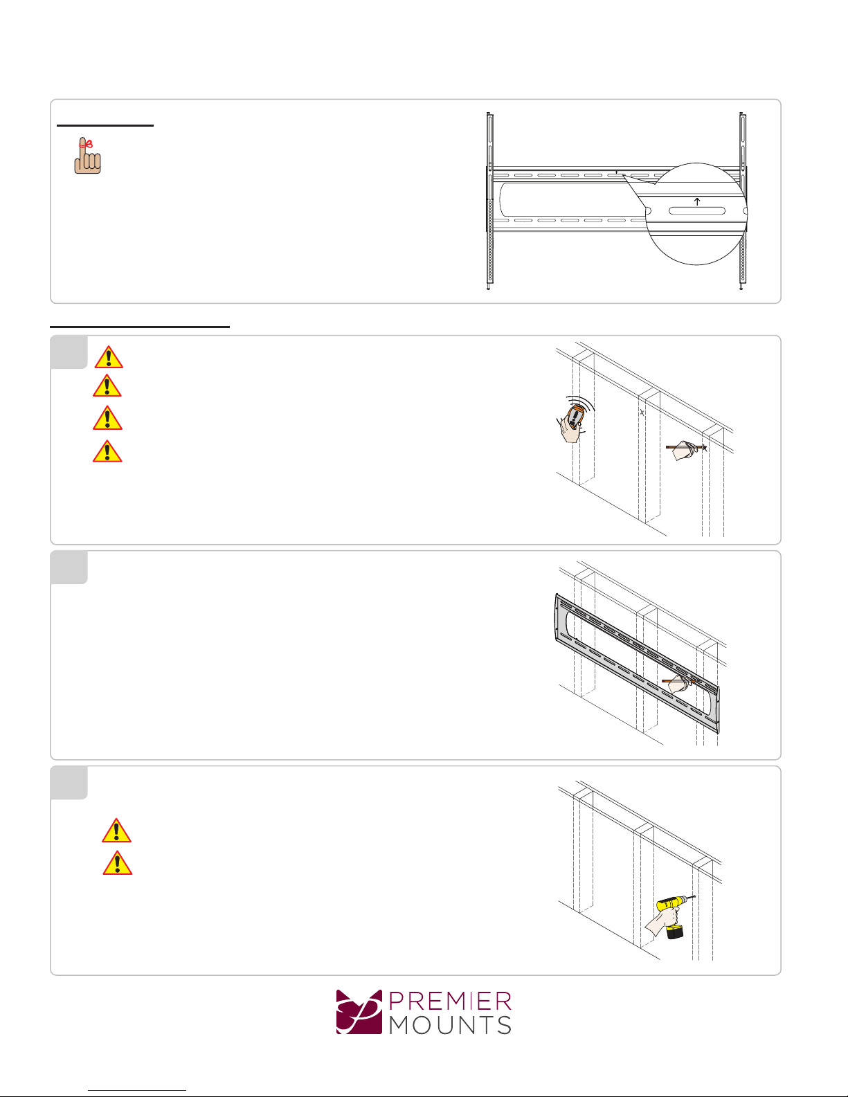
Directional Mounting Arrow
The Directional Mounting Arrow stamped into the top of the P5080F wall
mount indicates which edge is the top.
Wood Stud Installation
1
Minimum of 2 by 4 wood stud to be used
Minimum de 2 par 4 bois goujon pour être utilisé
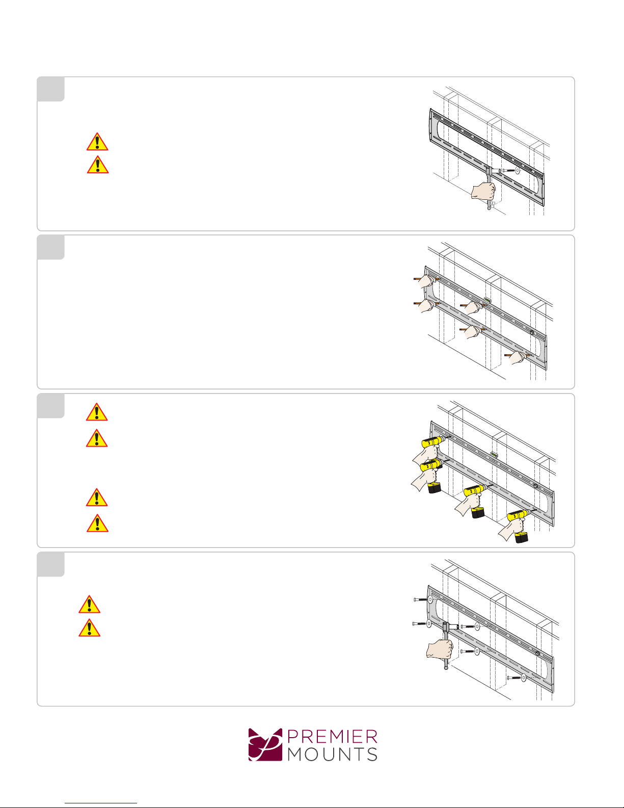
You must secure the wall plate to three (3) wall studs with a minimum of
six (6) lag bolts (2 lag bolts for each stud found).
Vous devez assembler la sablière sur trois (3) rivets à bois avec un
minimum de six (6) tirefonds (2 tirefonds pour chaque rivet trouvé).
1) Use a stud nder to determine the center of wall studs in the vicinity of the
wall plate.
2) Use a pencil to mark the center of each of the wall studs.
2
1) Place the wall plate against the wall in the desired viewing location.
2) Use a pencil to mark the upper right mounting location along the center of
the wall stud.
X
X
X
3
Drill a “pilot hole” in the center of the upper right mark using a 1/4” drill bit and
power drill.
Only use a 1/4″ drill bit when drilling the pilot holes.
N’utiliser qu’un foret de 1/4˝ lors du forage de guidage.
Page 4
www.mounts.com | North America 800.368.9700 | International +1-714-632-7100
Page 5
P5080F
Installation Guide
4
5
1) Place the wall plate against the wall and align it with the pilot hole.
2) Insert one (1) 5/16″ x 3″ lag bolt and one (1) 5/16″ washer into the
up per right mounting hole and tighten using a socket wrench and 1/2” socket.
Do not overtighten the lag bolt.
Éviter de trop serrer le tirefond.
1) Level the wall plate.
2) Use a pencil to mark the remaining ve (5) mounting locations along the
Center of each wall stud.
6
7
Two people are recommended for this step; one person to level the wall
plate and another person to drill the pilot holes.
Il est recommandé deux personnes pour cette étape : une personne pour niveler la sablière et une autre personne pour percer
le forage de guidage.
Drill a “pilot hole” in the center of each of the marks with a power drill and a 1/4″
drill bit.
Only use 1/4″ drill bit when drilling the pilot holes.
N’utiliser qu’un foret de 1/4” lors du forage de guidage.
1) Insert one (1) 5/16” x 3” lag bolt and one (1) 5/16” washer into each pilot hole.
2) Tighten all lag bolts using a socket wrench and 1/2” socket.
Do not overtighten the lag bolts when attaching the mount to the wall. Improper
Installation may result in personal injury or property damage.
Éviter de trop serrer les tirefonds lors de la xation du support au
mur. Une installation incorrecte peut entraîner des blessures ou
des dommages matériels.
www.mounts.com | North America 800.368.9700 | International +1-714-632-7100
Page 5
Page 6
P5080F
Installation Guide
Concrete Installation
8
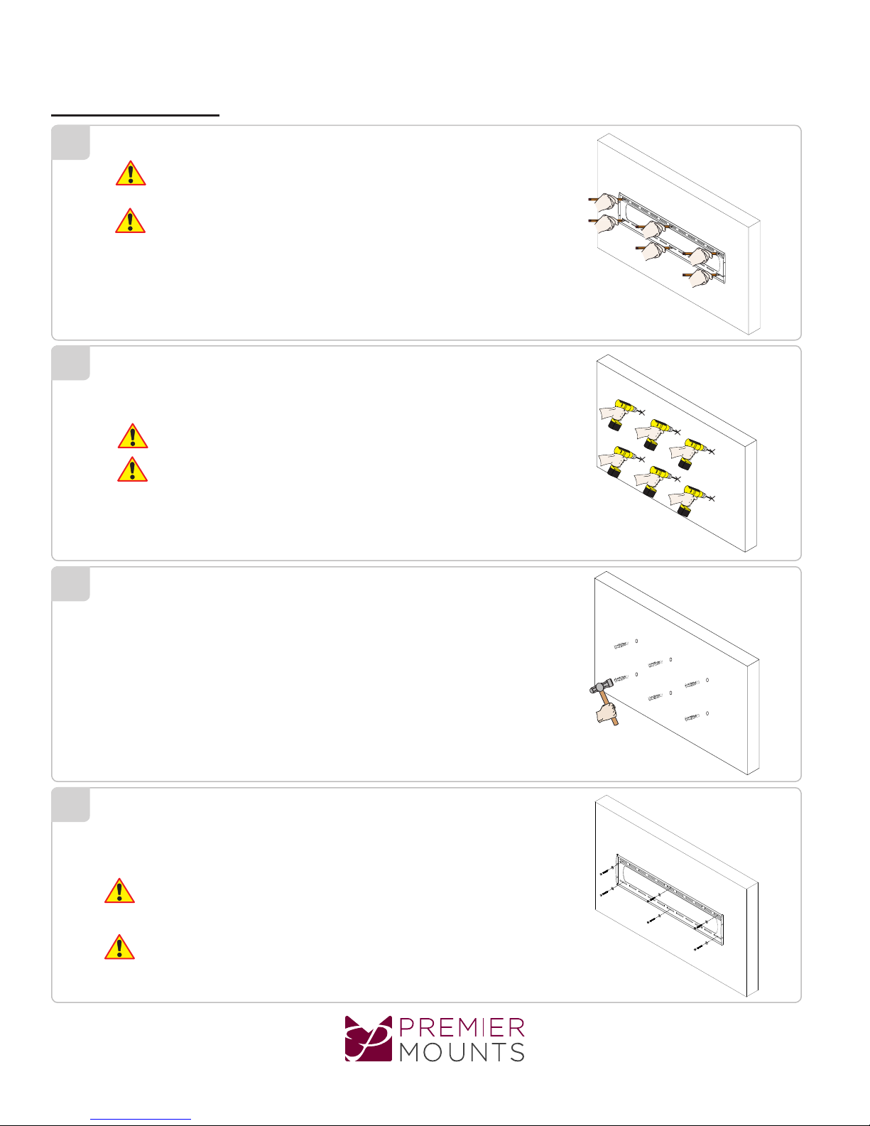
Two people are recommended for this step: one person to level the wall
plate and another person to mark the mounting locations.
Il est recommandé deux personnes pour cette étape : une personne pour
niveler la sablière et une autre personne pour marquer les emplacements
de montage.
9
10
Drill six (6) pilot holes of each mark using a drill and 3/8” masonry drill bit.
Drill 3 inches deep.
Only use a 3/8" masonry drill bit when drilling pilot holes.
N’utiliser qu’un foret de 3/8” lors du forage de guidage.
Insert the Finned Anchors into each pilot hole.
Lightly tap each Finned Anchors into place with a hammer.
11
Page 6
1) Insert one (1) 5/16” x 3” Lag Bolt and one (1) 5/16” washer into each
pilot hole.
2) Tighten all lag bolts using a socket wrench and 1/2” socket.
Do not overtighten the lag bolts when attaching the mount to the
wall. Improper installation may result in personal injury or property
damage.
Éviter de trop serrer les tirefonds lors de la xation du support au
mur. Une installation incorrecte peut entraîner des blessures ou des
dommages matériels.
www.mounts.com | North America 800.368.9700 | International +1-714-632-7100
Page 7
Selecting the Mounting Hardware
Small Straw or Toothpick
Marking the 1/8”
Allowance
P5080F
Installation Guide
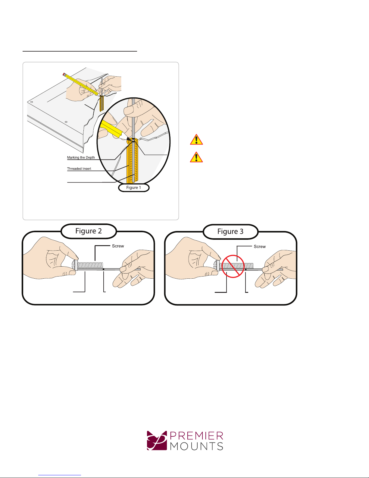
1) Insert a small straw or toothpick into the threaded inserts found on the
back of the at-panel.
2) Use a pencil to mark the depth of the threaded insert on the small straw
or toothpick.
3) Mark the straw or toothpick 1/8” above the depth of the threaded insert,
as shown in Figure 1.
4) Insert the small straw or toothpick into the remaining threaded inserts
to compare and verify their depth using the straw or toothpick’s 1/8”
allowance mark.
5) Locate the correct diameter screw for the threaded insert.
If the screw you selected is longer than the 1/8” allowance mark on
the small straw or toothpick, as shown in Figure 2 and Figure 3, do
not use this screw. The screw length must not bypass the mark.
Si la vis que vous sélectionnez est plus longue que la marque du
jeu maximal de 1/8” sur le paillon ou le cure-dents, comme illustré
sur le schéma 2 et le schéma 3, veuillez ne pas utiliser cette vis. La
longueur de la vis doit dévier la marque.
6) Test each size of the screws provided.
The correct screws should thread easily into themounting point and
not pull out when tension is applied.
Small Straw
or Toothpick
Depth Plus 1/8” Allowance
Mark
www.mounts.com | North America 800.368.9700 | International +1-714-632-7100
Small Straw
or Toothpick
Depth Plus 1/8” Allowance
Mark
Page 7
Page 8
P5080F
Installation Guide
Universal Washer Installation
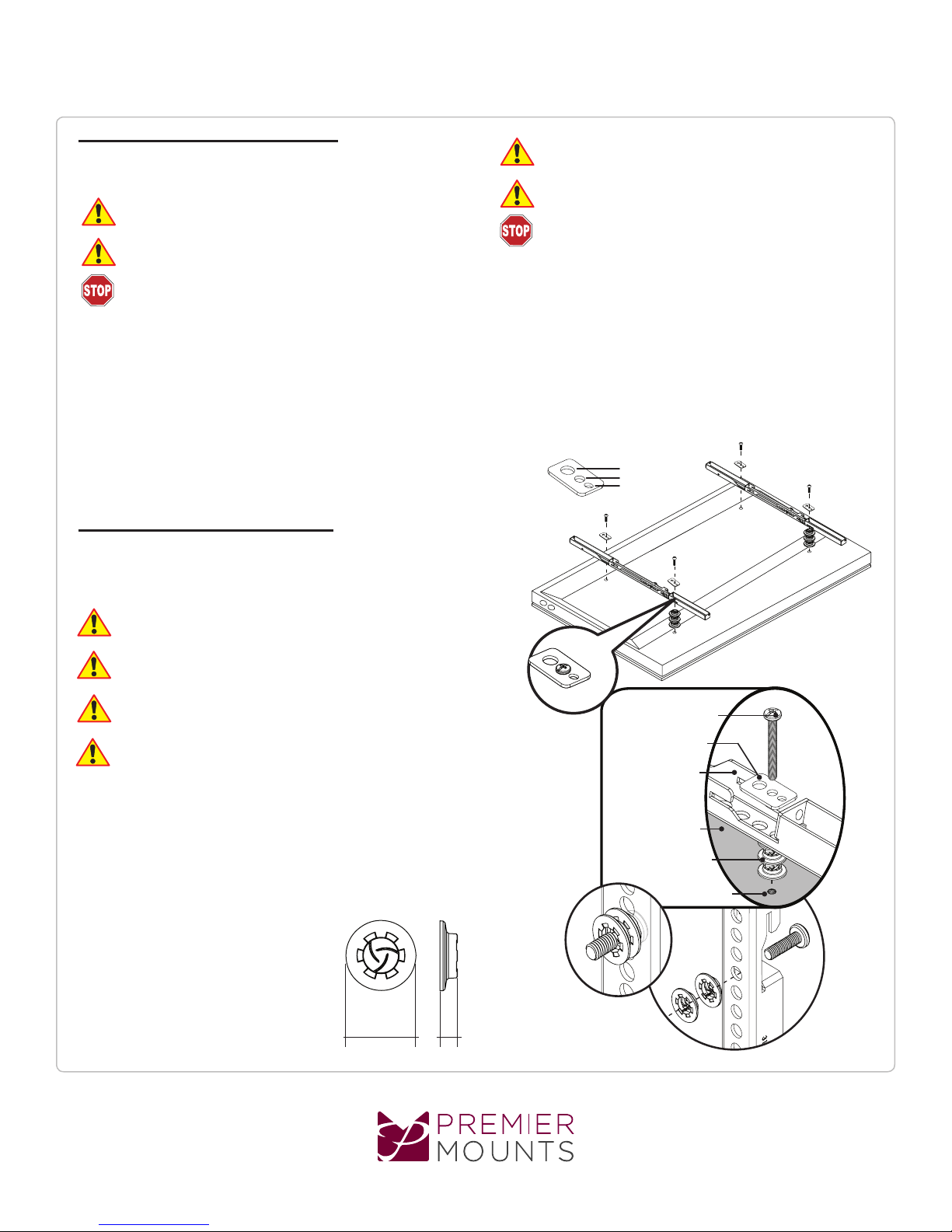
Premier Mounts’ Universal Washers are designed to accommodate the various
M4, M5, M6 and M8 hole sizes required by at panels.
Do not place excessive pressure on the back of the at panel, as this
may damage your at panel.
The Universal Washer must be installed between the head of the
mounting screw and the mounting bracket as shown.
Does your at panel have:
● Recessed mount points?
● Uneven mount points?
● A curved back?
● Any obstruction near the mount point?
If Yes, you must install Universal Spacers. Remove the mounting brackets,
Universal Washers, and mounting screws from the back of the at panel.
Proceed to the “Universal Spacer Installation” section.
If No, skip to the “Locking and Leveling Screw Installation” section.
Universal Spacer Installation
Premier Mounts’ Universal Spacers allow you to attach the mounting bracket
to at panels which have recessed or uneven mount points. Each Universal
Spacer adds 1/4” to the distance between the mounting bracket and your at
panel.
Éviter de placer une pression excessive à l’arrière de l’écran plat, car
cela risque d’endommager votre écran plat.
La rondelle tous usages doit être installée entre le chapeau de la vis de
xation et le support de montage comme illustré.
Votre écran plat est-il muni de :
● Points de montage encastrés ?
● Points de montage inégaux ?
● Un plan arrière arrondi ?
● Une obstruction à l’emplacement du point d’assemblage ?
Si Oui, vous devez installer des entretoises universelles. Enlever les supports
de montage, les rondelles universelles, et les vis de montage de l’arrière de
l’écran plat. Passer à la section « Installation d’entretoises universelles ».
Si non, aller à la section « Verrouillage et mise à niveau de l’installation de
la vis ».
M8
M5, M6
M4
The Universal Spacers must be stacked and oriented as shown.
Les entretoises tous usages doivent être empilées et orientées
comme illustré.
The Universal Spacers must only be installed between the mounting
bracket and your at panel.
Les entretoises tous usages ne doivent être installées qu’entre le
support de montage et votre écran plat.
The Universal Spacers will t M4, M5, M6 and M8 screw sizes.
Proceed to the “Locking and Leveling Screw Installation” section.
1˝ ¼˝
Mounting Screw
Universal Washer
Mounting Bracket
Flat Panel
Universal Spacer
Mount Point
Page 8
www.mounts.com | North America 800.368.9700 | International +1-714-632-7100
Page 9
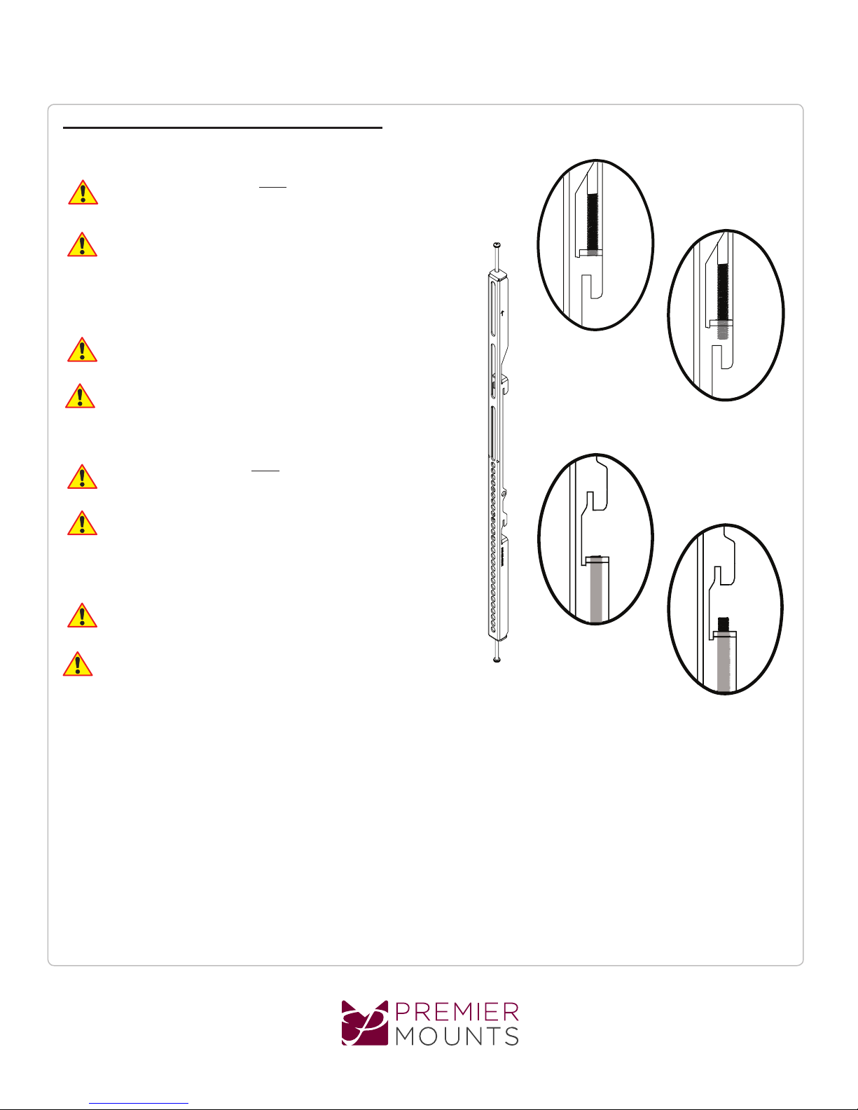
Locking and Leveling Screw Installation
Leveling Screw Installation
You must install the leveling screws before you attach the mounting
bracket to the back of the at panel. The leveling screws consists of
two (2) M6 x 250mm screws.
Vous devez installer les vis de réglage aven de xer le support de
montage à l’arrière de l’écran plat. Les vis de réglage se composent
de deux (2) de M6 x 250 mm.
Thread one (1) leveling screw into the top mounting hole on each of the mounting
brackets. Make sure the leveling screw is securely threaded into the mounting
tab before processing.
P5080F
Installation Guide
Do not thread the leveling screw any further once it is even with the
mounting tab. Threading the leveling screw any further will prevent you
from safely attaching the at panel to the wall plate.
Éviter d’enler davantage la vis de réglage une fois qu’elle parvient au niveau
de la patte de xation. Le letage excessif de la vis de réglage au-delà de ce
point gênera le xage correct de l’écran plat sur la sablière.
Locking Screw Installation
You must install the locking screw before you attach the mounting bracket to
the back of the at panel. The locking screws consists two (2) M6 X 250 mm
screws.
Vous devez installer les vis de réglage aven de xer le support de
montage à l’arrière de l’écran plat. Les vis de réglage se composent
de deux (2) de M6 x 250 mm.
Thread one (1) locking screw into the bottom mounting hole on each of the
mounting brackets. Make sure the locking screw is securely threaded into the
mounting tab before proceeding.
Do not thread the locking screw any further once it is even with the mounting tab. Threading the locking screw any further will prevent you from safely
attaching the at panel to the wall plate.
Éviter d’enler davantage la vis de blocage une fois qu’elle parvient au
niveau de la patte de xation. Le letage excessif de la vis de réglage
au-delà de ce point gênera le xage correct de l’écran plat sur la
sablière.
Leveling Screw
Correctly Threaded
Leveling Screw
Threaded Too Far
Locking Screw
Correctly Threaded
Locking Screw
Threaded Too Far
www.mounts.com | North America 800.368.9700 | International +1-714-632-7100
Page 9
Page 10
P5080F
Installation Guide
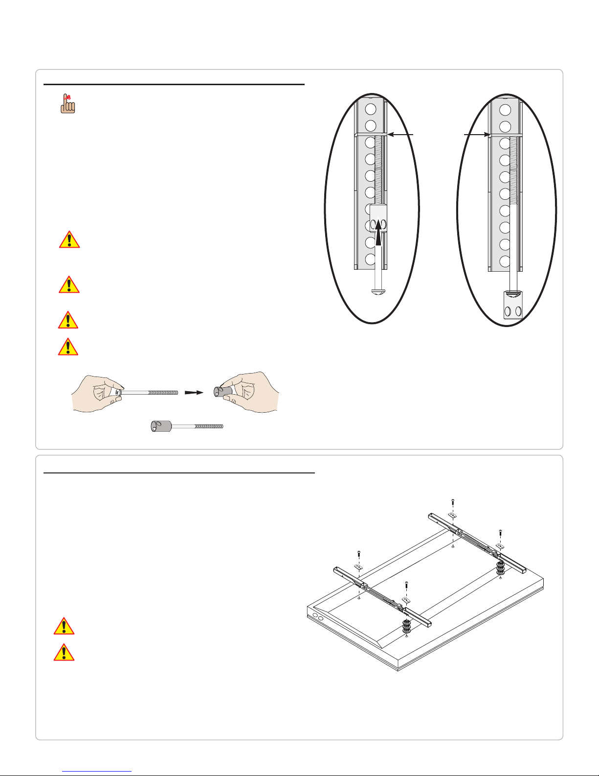
Lock-it™ Security Barrel Installation (Optional)
Optional security congurations include:
- PCB-CSL1 (sold separately)
- Padlock (Combination or Keyed; commercially
available)
Please read the following directions to install the security barrel:
1) Remove the locking screw from the mounting bracket.
2) Place the locking screw into and through the security barrel (see illustration below).
3) Re-insert the locking screw and security barrel into the mounting bracket.
4) Tighten the locking screw and security barrel until seated in the mounting tab.
Do not thread the locking screw any further once it is even with the
mounting tab (see illustration to the right). Threading the locking screw
any further will prevent you from safely attaching the at panel to the
wall plate.
Éviter d’enler davantage la vis de réglage une fois qu’elle parvient au niveau
de la patte de xation (voir illustration à droite). Le letage excessif de la vis
de réglage au-delà de ce point gênera le xage correct de l’écran plat sur la
sablière.
Do not overtighten the locking screw.
Mounting Tab
Éviter de trop serrer la vis de blocage.
Locking Screw
Lock-It™ Security
Barrel
Attaching the Mounting Bracket to the Flat Panel
This section presumes that you have read and understood these sections:
● Selecting the Proper Mounting Hardware
● Universal Washer Installation
● Universal Spacer Installation
1) Place your at panel screen-side down on a soft, at surface.
2) Identify the number and location of the thread inserts on the back of your
at panel.
3) Aligning the holes on each mounting bracket with the thread inserts on the
back of our at panel.
4) Secure each mounting bracket to your at panel by inserting a minimum of
two (2) screw per bracket.
Do not overtighten the mounting hardware.
Éviter de trop serrer le dispositif de montage.
Page 10
Page 11
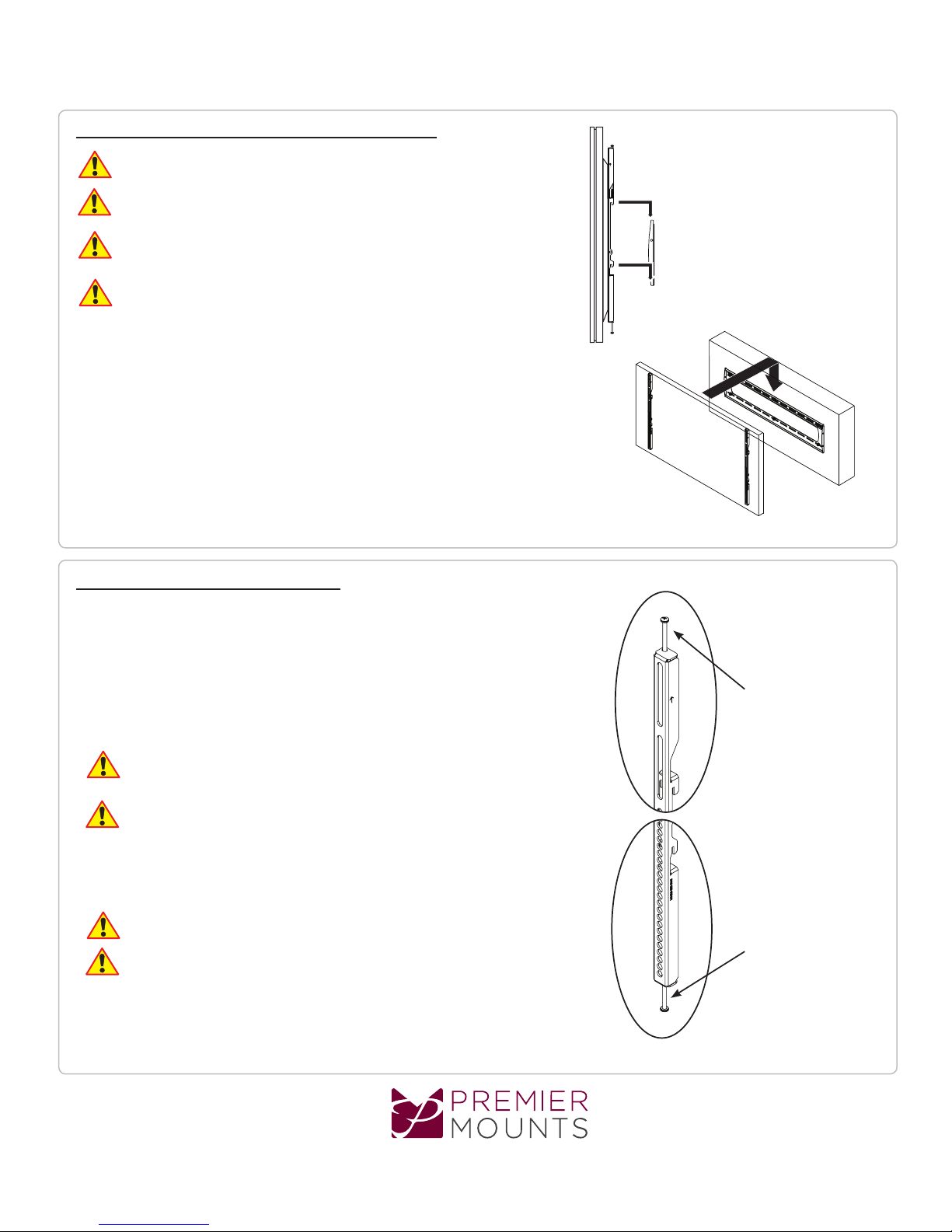
Attaching the Flat Panel to the Wall Plate
This section requires two people.
Cette section exige deux personnes.
Do not release your at panel until you are certain that top and bottom hooks of both mounting
brackets are securely seated on the upper and lower mounting rails of the wall panel.
Éviter de relâcher votre écran plat jusqu’à ce que vous vous assuriez que les crochets
de haut et de bas de tous les deux supports de montage sont bien posés sur les rails
de montage hauts et bas de la sablière.
1) Raise the at panel past the top and bottom mounting rails on the wall panel.
2) Slide the at panel down slowly, keeping it close to the wall.
3) Engage the top and bottom mounting brackets to the rails of the wall plate.
P5080F
Installation Guide
Mounting Bracket Adjustment
Leveling Screw Adjustment
If your at panel is tilted too far to one side, the leveling screws will allow you
compensate for this tilt by simply adjusting the screws with a screwdriver.
1) Loosen both locking screws.
2) Adjust the tilt of your at panel.
3) Tighten both locking screws.
Caution!
It is possible to dislodge your at panel while you level your at panel.
Use extreme caution until you tighten the locking screws.
Attention !
C’est possible de retirer votre écran plat pendant son réglage. User d’une
extrême prudence jusqu’au moment du serrage des vis de blocage.
Locking Screw Adjustment
After you have nished leveling your at panel, be sure to tighten the two (2) M6 x 250mm
locking screws, one on each mounting bracket.
Do not overtighten the locking screws.
Éviter de trop serrer les vis de blocage.
M6 x 250mm
Leveling Screw
(1 per Bracket)
M6 x 250mm
Locking Screw
(1 per Bracket)
www.mounts.com | North America 800.368.9700 | International +1-714-632-7100
Page 11
Page 12
P5080F
Installation Guide
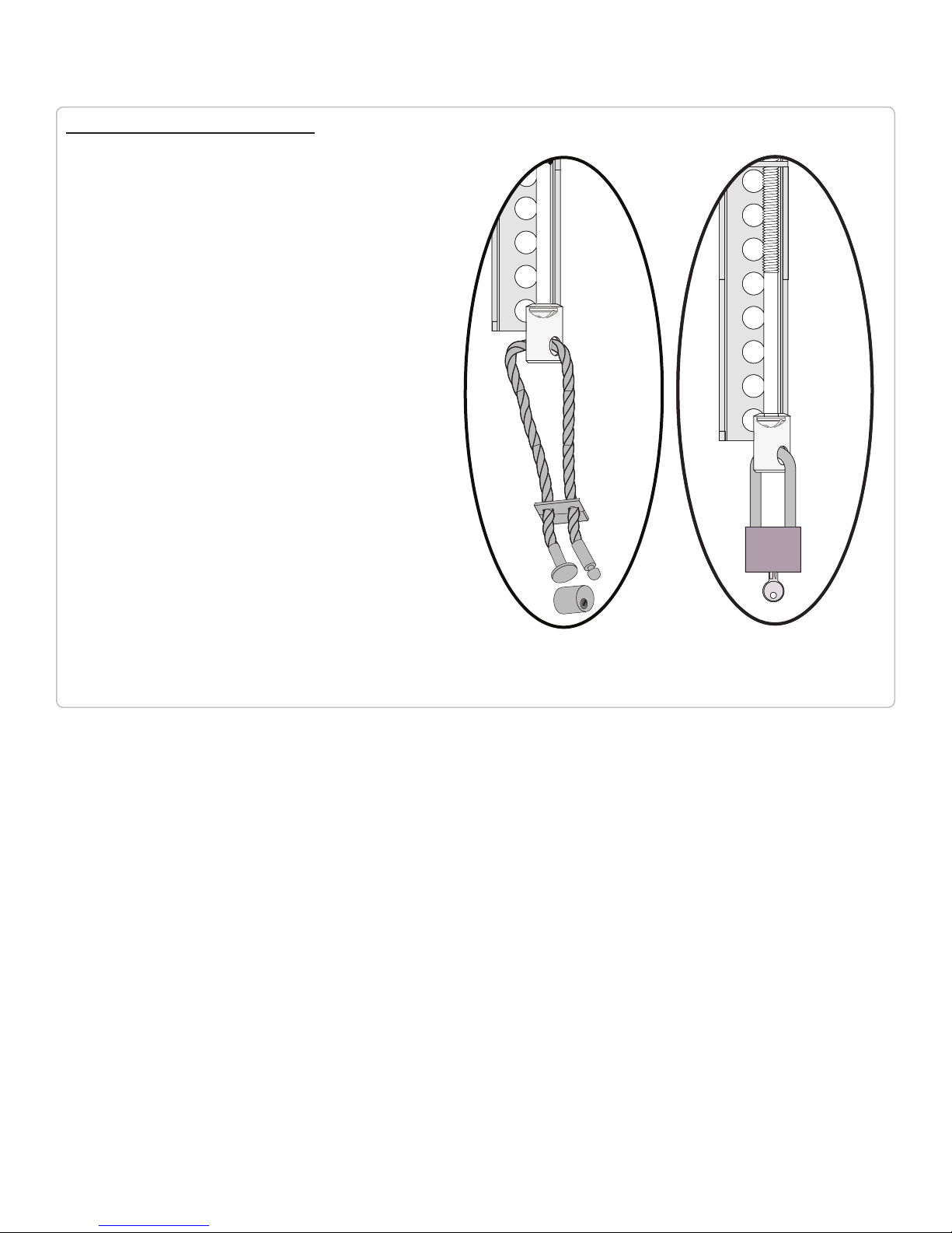
Utilizing the Security Barrel
Your P5080F Mount includes one (1) Security Barrel which can provide
additional theft deterrence for your at panel.
PCB-CSL1 Security Cable
1) Thread the cable through the hole on the security barrel.
2) Attach the PCB-CSL1 locking mechanism and secure it using the
supplied key.
Padlock
1) Place the locking hook through the hole of the security barrel.
2) Snap lock and locking hook together.
PCB-CSL1
Padlock
(Combination or Keyed)
Page 12
Page 13

P5080F
Installation Guide
PREMIER MOUNTS
LIMITED LIFETIME WARRANTY
What and Who is Covered by this Limited Lifetime Warranty
Premier Mounts warrants all mounting products to be free from defects in material and workmanship for the
lifetime of the original installation of the product.
What Premier Mounts Will Do
At the sole option of Premier Mounts, Premier Mounts will repair or replace any product or product part that is
defective. If Premier Mounts chooses to replace a defective product or part, a replacement product or part will
be shipped to you at no charge, but you must pay any related labor costs.
What is Not Covered: Limitations
Premier Mounts disclaims any liability for damage to mounts, adapters, displays, projectors, other property,
or personal injury resulting, in whole or in part, from improper installation, modication, use or misuse of its
products.
NOTWITHSTANDING ANYTHING TO THE CONTRARY IN THIS WARRANTY, THIS WARRANTY IS
LIMITED TO FIVE YEARS FROM THE DATE OF PURCHASE IN THE EVENT THAT THE WARRANTED PRODUCT IS COMMERCIALLY RENTED OUT.
Electrical products and components, such as ampliers, speakers, motors, switches remote controls and related
electrical items, are backed by a 3-year warranty.
Premier Mounts disclaims all other warranties, express or implied, including warranties of merchantability and
tness for a particular purpose. Premier Mounts is not responsible for incidental or consequential damages,
including but not limited to, inability to use its products or labor costs for removing and replacing defective
products or parts. Some states do not allow the exclusion or limitation of incidental or consequential damages,
so the above limitation or exclusion may not apply to you.
What Customers Must Do for Warranty Service
If you discover a problem that you think may be covered by the warranty, you must report it in writing to the
address below within thirty (30) days. Proof of purchase (an original sales receipt) from the original consumer
purchaser must accompany all warranty claims. Warranty claims must also include a description of the problem,
the purchaser’s name, address, and telephone number. General inquiries can be addressed to Premier Mounts
Customer Service at 1-800-368-9700. Warranty claims will not be accepted over the phone or by fax.
Premier Mounts
Attn: Warranty Claim
1321 S. State College Blvd.
Fullerton, CA 92831 USA
How State Law Applies
This warranty gives you specic legal rights, and you may also have other rights which vary from state to state.
Premier Mounts intends to make this manual accurate and complete. However, Premier Mounts makes no claim that the information contained herein covers all details,
conditions or variations, nor does it provide for every possible contingency in connection with the installation or use of this product. The information contained in this
document is subject to change without notice or obligation of any kind. Premier Mounts makes no representation of warranty, expressed or implied, regarding the
information contained herein. Premier Mounts assumes no responsibility for accuracy, completeness or sufciency of the information contained in this document.
Page 13
www.mounts.com | North America 800.368.9700 | International +1-714-632-7100
9531-208 -E01- 0X_9
 Loading...