

Page 1
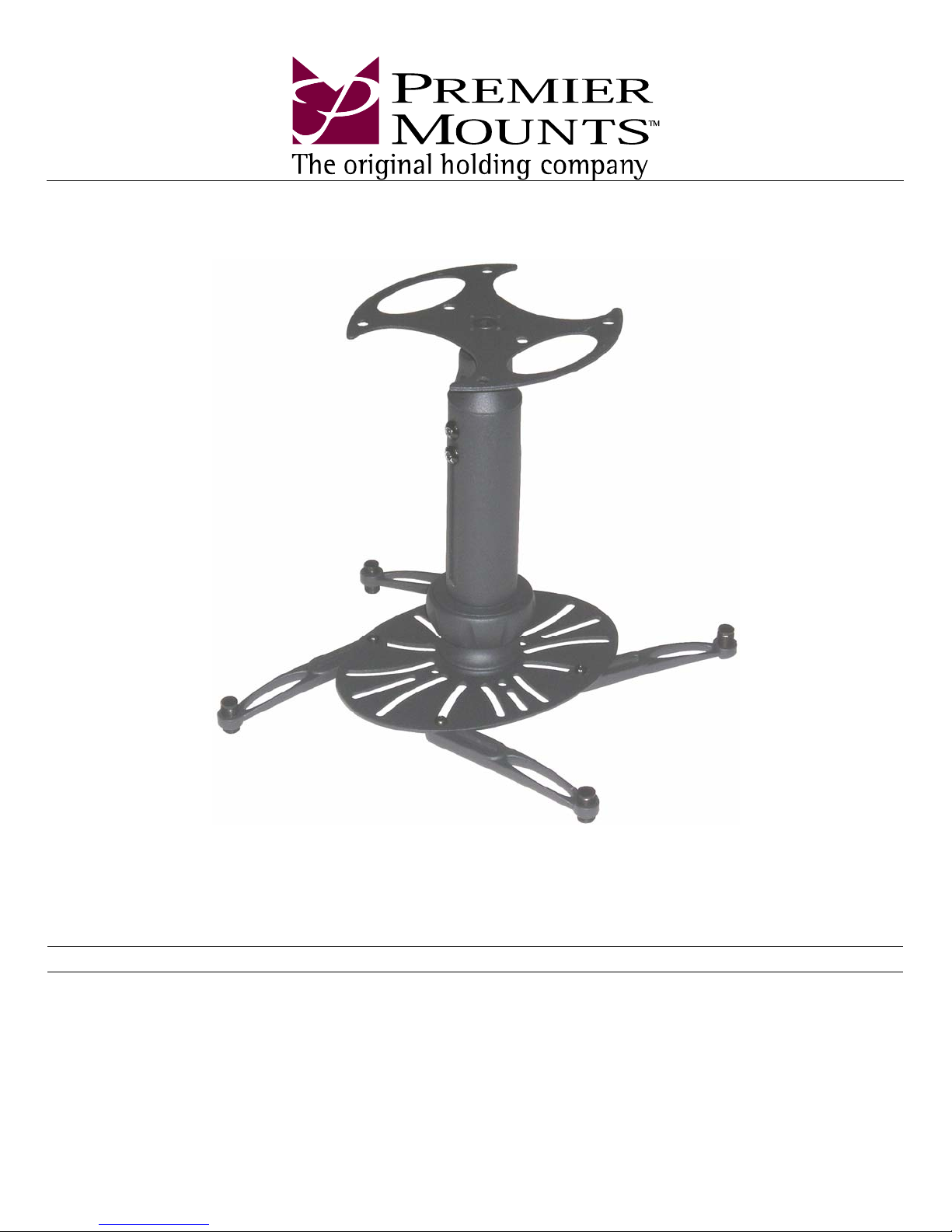
INSTALLATION MANUAL
NORTH AMERICA
3130 East Miraloma Avenue
Anaheim, CA 92806 USA
USA and Canada –
Phone: 800-368-9700
Fax: 800-832-4888
Other Locations – Phone: (001)-714-632-7100; Fax: (001)-714-632-1044
©Premier Mounts 2007
9530-005-021-01
NOVA-EXT
Versatile Projector Mount
Model: NOVA-EXT
EUROPE
Swallow House,
Shilton Industrial Estate,
Shilton, Coventry, England CV79JY
Phone: +44 (0) 2476 614700
Fax: +44 (0) 2476 614710
AUSTRALIA, NEW ZEALAND, OCEANIA
(DISTRIBUTOR)
P.O. Box 295
Mordialloc Victoria 3195
Australia
Phone: 039586 6330
www.premiermounts.com.au
Page 2
NOVA-EXT
Congratulations on the purchase of your new Premier Mounts NOVA-EXT Versatile Projector Mount. The
NOVA-EXT features our exclusive SpiroLock™ Technology, which provides the installer with quicker
installation times and peace of mind. To truly appreciate the speed, style and versatility of the NOVA-EXT,
please read this installation manual completely.
Table of Contents
Warning Statements.............................................................................................................................................................................. - 2 -
Parts List............................................................................................................................................................................................... - 3 -
Installation Tools .................................................................................................................................................................................. - 4 -
Features................................................................................................................................................................................................. - 4 -
Selecting the Proper Mounting Hardware............................................................................................................................................. - 4 -
Attaching the Mount............................................................................................................................................................................. - 5 -
Single Mounting Point Installation....................................................................................................................................................... - 6 -
Ceiling Installation................................................................................................................................................................................ - 7 -
Concrete Mounting............................................................................................................................................................................... - 8 -
Connecting the SpiroLock™ Assembly................................................................................................................................................- 8 -
Adjusting the Projector......................................................................................................................................................................... - 9 -
Safety Screw Installation .................................................................................................................................................................... - 10 -
Plastic Cap Installation ....................................................................................................................................................................... - 10 -
Disconnecting the SpiroLock™ Assembly......................................................................................................................................... - 11 -
Height Adjustment.............................................................................................................................................................................. - 13 -
Optional Mounting Configurations..................................................................................................................................................... - 14 -
Technical Specifications..................................................................................................................................................................... - 15 -
Warranty............................................................................................................................................................................................. - 16 -
Warning Statements
WARNING: PREMIER MOUNTS DOES NOT WARRANT AGAINST DAMAGE CAUSED BY THE USE OF ANY PREMIER MOUNTS PRODUCT FOR
WARNING:
WARNING:
WARNING:
WARNING:
PURPOSES OTHER THAN THOSE FOR WHICH IT WAS DESIGNED OR DAMAGE CAUSED BY UNAU THORIZED ATTACHMENTS OR
MODIFICATIONS, AND IS NOT RESPONSIBLE F OR ANY DAMAGES, CLAIMS, D EMANDS, SUITS, ACTIONS OR C AUSES OF ACTION
OF WHATEVER KIND RESULTING FROM, ARISING OUT OF OR IN ANY MANNE R RELATING TO ANY SUCH USE, ATTACHMENTS
OR MODIFICATIONS.
THE CEILING STRUCTURE MUST BE CAPABLE OF SUPPORTING MORE THAN 65LBS. IF NOT , THE CEILING STRUCTURE MU ST BE
REINFORCED. PROPER INSTALLATION PROCEDURE BY A QUALIFIED SERVICE TECHNICIAN, AS OUTLINED IN THE
INSTALLATION INSTRUCTIONS, MUST BE ADHERED TO. FAI LURE TO DO SO C OULD RESUL T IN SERIOUS PER SONAL INJURY , OR
EVEN DEATH.
SAFETY MEASURES MUST BE PRACTICED AT ALL TIMES DURING THE INST ALLATION OF THIS PRODUCT. USE PROPER SAF ETY
GEAR AND TOOLS FOR THE INSTALLATION PROCEDURE TO PREVENT PERSONAL INJURY.
THE MAXIMUM WEIGHT PROJECTOR THAT CAN BE USED WITH THIS MOUNT IS 65LBS. EXCEEDING THIS WEIGHT LIMIT COULD
CAUSE DAMAGE TO THE MOUNT, TO THE PROJECTOR OR TO YOURSELF.
PRIOR TO THE INSTALLATION OF THIS PRODUCT, THE INSTALLATION INSTRUCTIONS SHOULD BE READ AND COMPLETELY
UNDERSTOOD. THE INSTALLATION INSTRUCT IONS MUST BE READ TO PREVENT PERSONAL INJURY AND PROPERTY DAM AGE.
KEEP THESE INSTALLATION INSTRUCTIONS IN AN EASILY ACCESSIBLE LOCATION FOR FUTURE REFERENCE.
Indicates that the power plug is to be disconnected from the power
outlet.
Safety precautions must be taken at all times. Customer Service – (800) 368-9700
Warning and Caution statements.
Do not install on a structure that is prone to vibration, movement or chance of impact. Failure to do so could result in damage to the projector and/or damage to
the mounting surface.
Do not install near heater, fireplace, direct sunlight, air conditioning or any other source of direct heat energy. Failure to do so may result in damage to the
projector and could increase the risk of fire.
A qualified person should perform the installation procedure. Injury and/or damage can result fr om dropping or mishandling the projector
Contact Premier Mounts with any questions –
Technical Support – [email protected]
Page - 2 - Installation Manual
Page 3
NOVA-EXT
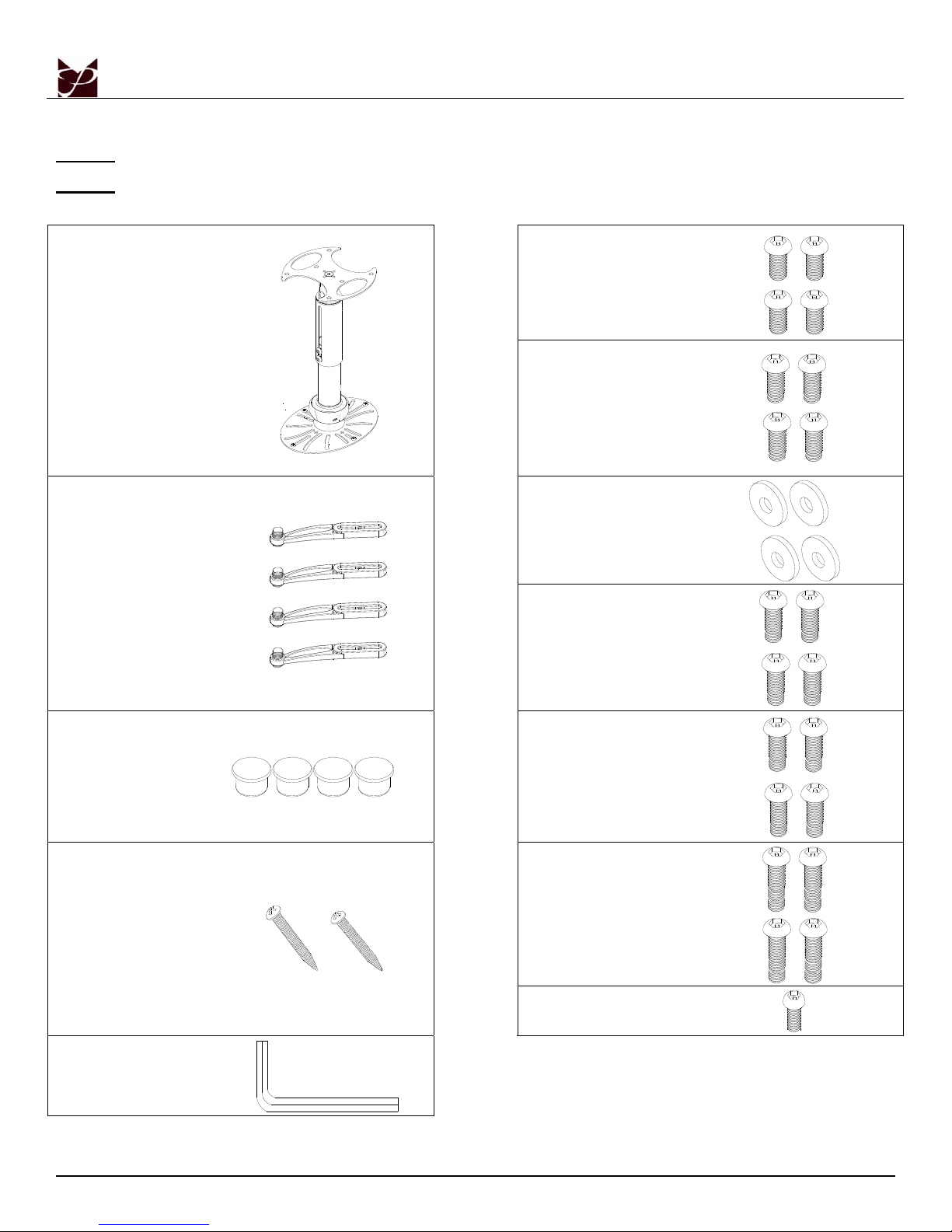
Parts List
NOTE: Please familiarize yourself with all components contained herein.
NOTE: Please review all WARNING and CAUTION statements (see Page 2) before beginning the
installation of the NOVA-EXT.
M2.5 X 8mm Security
Screw (Qty 4)
NOVA-EXT Mount
(Qty 1)
Mounting Legs
(Qty 4)
Plastic Barrel Caps (Qty 4)
M3 x 16mm Security
Screw
(Qty 4)
M3 Flat Washers
(Qty 4)
M4 x 12mm Security
Screw
(Qty 4)
M5 x 12mm Security
Screw
(Qty 4)
#14 x 2” Wood Screws
(Qty 2)
M5 Security Allen Wrench
(Qty 1)
Installation Manual Page - 3 -
M6 x 12mm Security
Screw (Qty 4)
¼ – 20 x 5/16” Security
Screw (Qty 1)
Page 4
NOVA-EXT
Installation Tools
Portable Drill Soft Material/ Blanket Pencil
Tape Measure Ladder M5 Security Allen Wrench (Supplied)
1/8” Drill Bit (Wood Installation – Commercially Available)
Masonry Bit (Concrete Installation – Commercially Available)
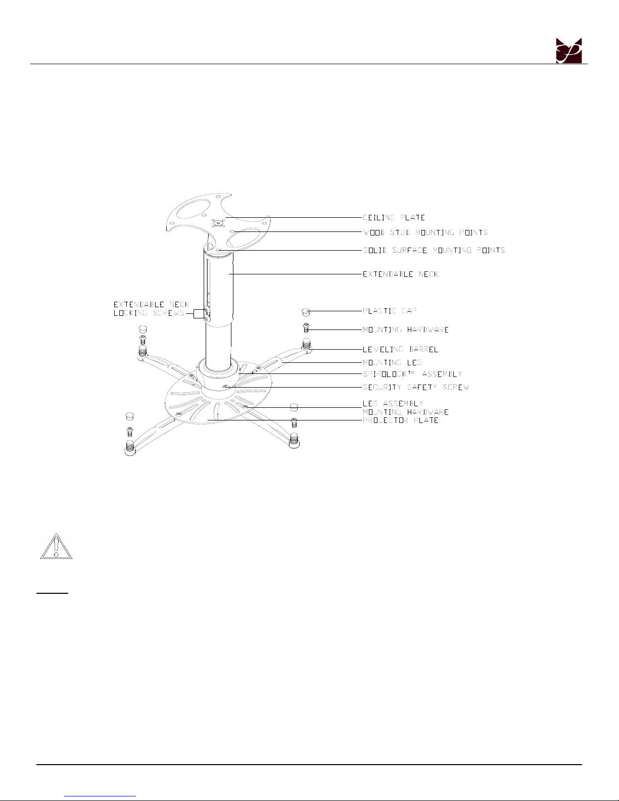
Features
Selecting the Proper Mounting Hardware
1. Turn the projector over and locate the mounting points.
2. Test each size of the screws provided.
3. The correct screws should thread easily into the mounting point and not pull out when pressure is applied.
DO NOT OVERTIGHTEN YOUR MOUNTING SCREWS TO THE PROJECTOR CHASSIS. USING THE
INCORRECT SCREW DEPTH MAY CAUSE DAMAGE TO YOUR PROJECTOR.
NOTE: The optional M3 flat washers may be used to decrease the screw depth of either the M2.5 x 12mm screws or the M3 x
16mm screws. Place a M3 flat washer inside the leveling barrel and then insert the mounting screw. DO NOT
OVERTIGHTEN THIS SCREW.
Page - 4 - Installation Manual
Page 5
NOVA-EXT
Attaching the Mount
Unpack the NOVA-EXT Mount and familiarize yourself with the components. Before proceeding, the SpiroLock™ must be separated
(please refer to Disconnecting the SpiroLock™ Assembly, page 11). Please take time before you install the NOVA-EXT to determine
the location of where the NOVA-EXT will be mounted.
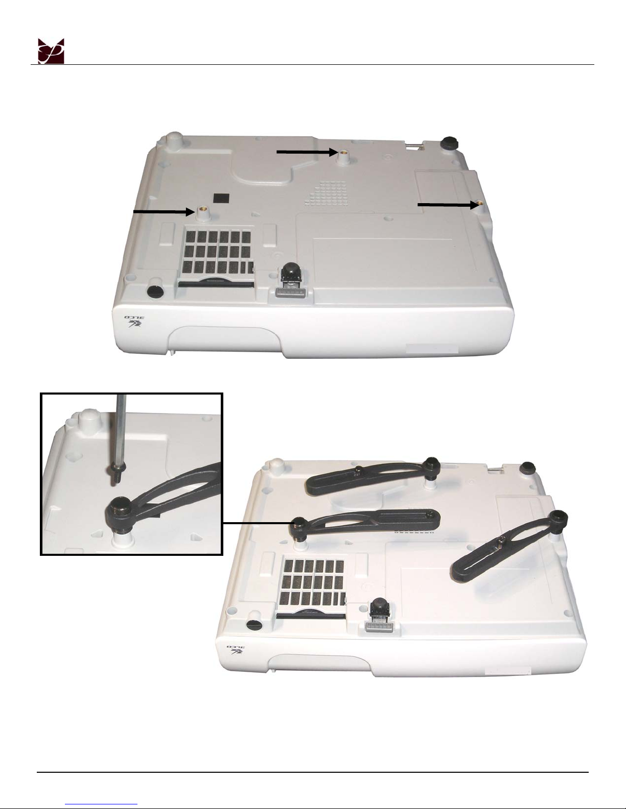
1. Locate the mounting points on the bottom of the projector (see arrows above for sample mounting points).
2. Attach the appropriate number of mounting legs to the projector using the corresponding mounting hardware (see Page 3, Selecting the Proper
Mounting Hardware).
3. If the mounting legs need to be leveled, rotate the leveling barrels by hand to level the mounting bracke t.
4. To raise the mounting legs, rotate the leveling barrel clockwise. To lower the mounting leg, rotate the leveling barrel counterclockwise.
5. When the desired position is achieved, tighten the mounting screws to the projector.
Installation Manual Page - 5 -
Page 6
NOVA-EXT
Mounting Leg
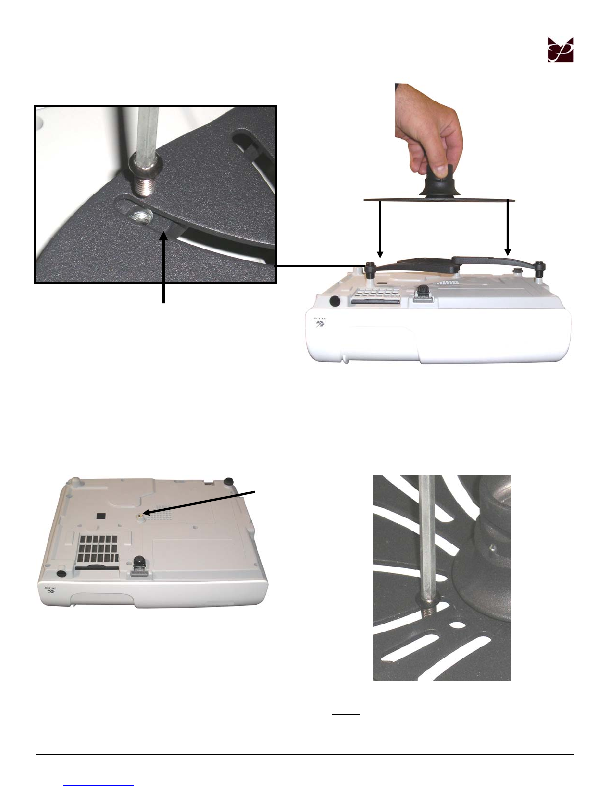
6. Secure the legs to the projector plate by screwing M6 x 12mm security screws into the M6 square nut (do not overtighten) on the
mounting legs. Tighten all security screws at this time.
7. Secure the legs to the projector plate by screwing M6 x 12mm security screws into the M6 square nut (do not overtighten) on the
mounting legs.
Single Mounting Point Installation
Mounting Point
If your projector has only one mounting point, a ¼-20 x 5/16”
screw must be used to attach the mount to the projector. Please
refer to the following three steps:
1. Determine where the mounting point is located.
Page - 6 - Installation Manual
2. Place the projector plate over the mounting point.
3. Insert the ¼-20 x 5/16” security screw.
NOTE
: This screw will use a standard hole when mounting.
Page 7
NOVA-EXT
Ceiling Installation
NOTE: During shipment, the NOVA-EXT comes assembled. Please refer to Page 11, “Disconnecting the SpiroLock™
Assembly” for instructions as to how the SpiroLock™ is disassembled.
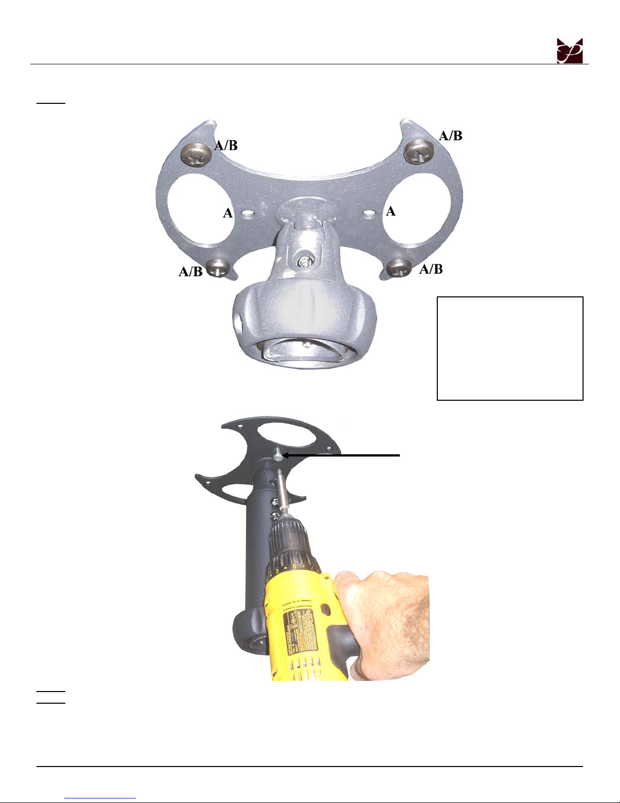
Wood studs: Where denoted with
the letter ‘A’, mark these locations
for wood stud installation.
A/B - Where denoted with the
letters ‘A/B’, these locations
specify that either wood screws or
concrete anchors may be used for
installation, depending on the
surface.
#14 x 2” Wood Screw
NOTE: Use a 1/8” drill bit to pre-drill the mounting holes before securing the wood screws (supplied).
NOTE: Use a masonry bit to pre-drill the mounting holes in the concrete surface (see Concrete Mounting, page 8).
1. Use two (2) #14 x 2” wood screws (supplied) to attach the ceiling plate to the wooden ceiling stud.
Installation Manual Page - 7 -
Page 8
NOVA-EXT
Concrete Mounting
NOTE: The NOVA-EXT can be mounted to a ceiling with a minimum 6” thickness. Concrete wedge anchors must be used for
concrete installation. It is recommended that ¼” wedge anchors be used. A masonry bit must be used to drill the pilot hole.
These items can be purchased at your local hardware store.
1. Begin by placing the ceiling plate into position against the ceiling, keeping it level.
2. Mark off four holes to be used for securing the mount and place the ceiling plate aside.
3. Next, drill holes using the appropriate masonry bit for your anchor.
4. Insert a concrete anchor into each hole.
5. If necessary, a hammer can be used to lightly tap each anchor into place so that they are flush with the ceiling.
6. Once all of the anchors are in place, move the ceiling plate back into position.
7. Attach the nut onto the threaded shaft that is protruding from the ceiling.
8. Do not tighten until all nuts are in place.
Connecting the SpiroLock™ Assembly
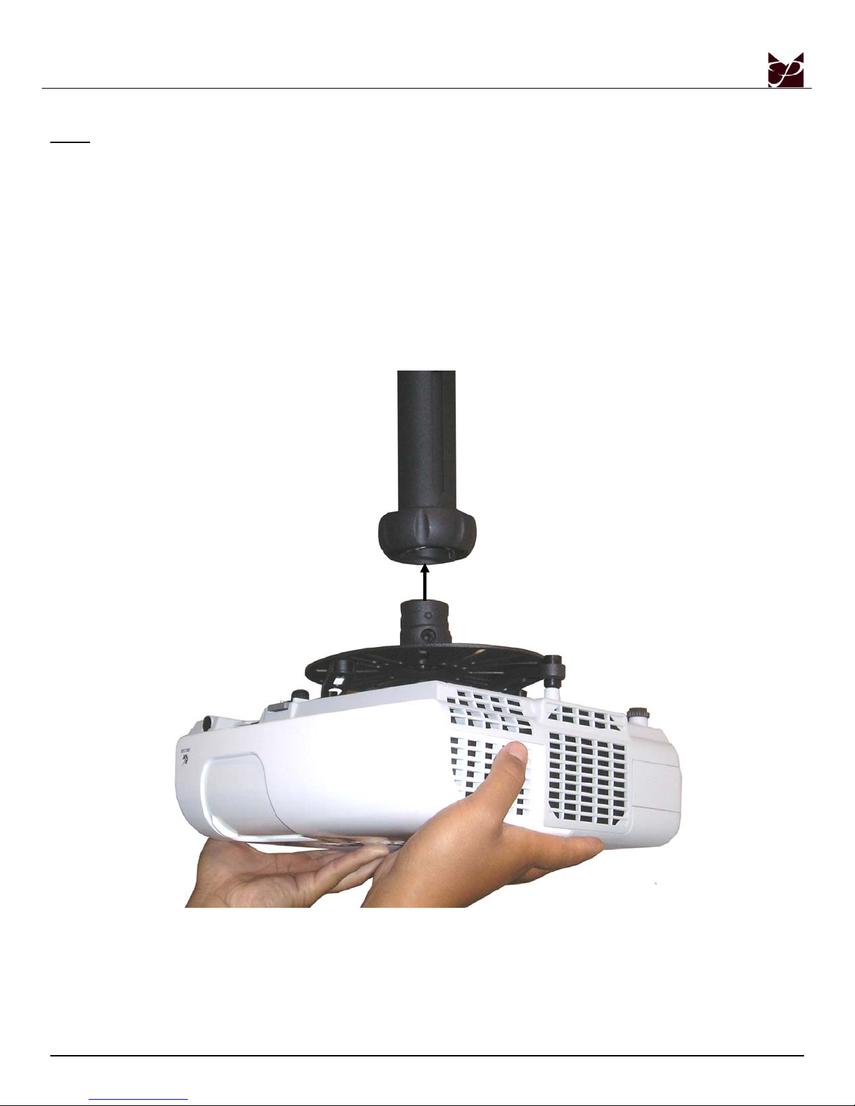
1. Slowly raise the projector toward the upper assembly.
Page - 8 - Installation Manual
Page 9
NOVA-EXT
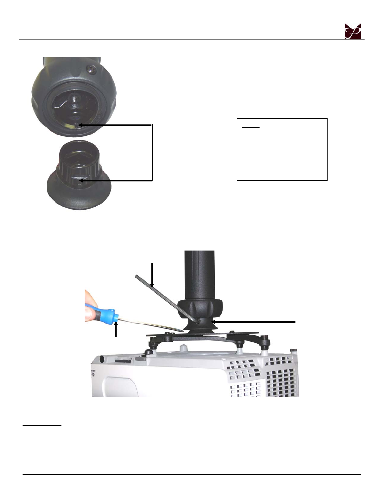
Mounting Notches
NOTE: In order for the
NOVA-EXT to connect, the
four (4) notches that are located
inside must be lined up. If they
are aligned properly, an audible
“click” will be heard while the
SpiroLock™ collar engages.
2. Push the two units together, until an audible ‘click’ will be heard (see NOTE), signifying that the SpiroLock™ assembly is
together. Before proceeding, ensure that the SpiroLock™ is securely holding the projector.
Adjusting the Projector
M5 Allen Wrench
Spindle
Screwdriver
To adjust the projector:
1. Firmly grasp the projector in both hands, and slowly tilt either forward or backward, side-to-side to adjust and level.
2. Tighten the M5 security screw using the M5 Allen wrench to keep the image aligned on the screen.
IMPORTANT
adjustments. In order to make these adjustments, do not completely tighten the adjustment locking screws at this
time. Place the tip of the screwdriver between the projector plate and the lip of the spindle and adjust using the
screwdriver. Once the adjustments have been made, tighten the adjustment screws on each side using the supplied
M5 Allen wrench.
: In the event that precision adjustments are needed, a flat tip screwdriver may be used to make small, even
Page - 9 - Installation Manual
Page 10
NOVA-EXT
Safety Screw Installation
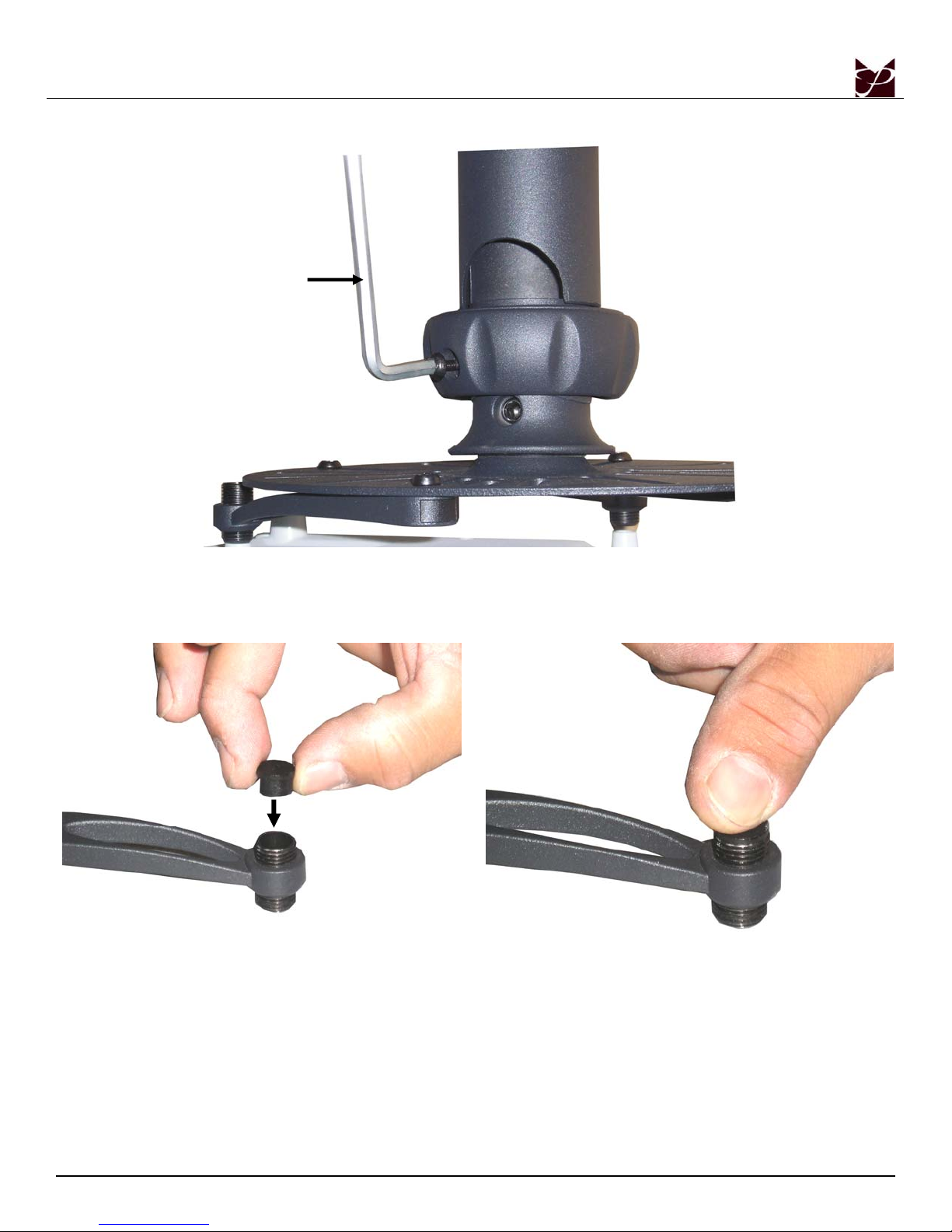
M5 Allen Wrench
1. The M4 x 12mm safety screw (located on the SpiroLock™ collar) must be tightened securely before installation is complete. If
the M4 x 12mm safety screw is not properly secured, there will be an increased risk of attachment failure, which cou ld result in
damage to the projector or personal injury.
Plastic Cap Installation
1. After all positioning has been determined, check and make sure that all hardware is secure.
2. Place a plastic cap over each leveling barrel and firmly push the plastic cap into place.
Page - 10 - Installation Manual
Page 11
NOVA-EXT
Disconnecting the SpiroLock™ Assembly
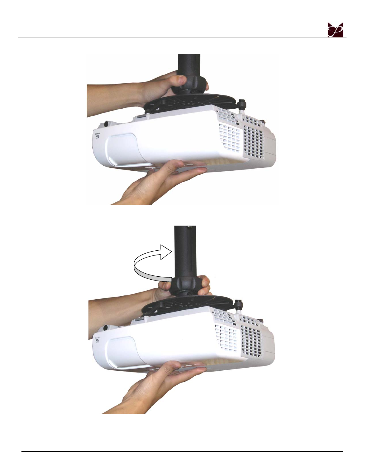
1. Place one hand under the projector (this hand will support the projector while it is being disconnected).
2. While holding the projector with one hand, grasp the SpiroLock™ collar and turn the collar counterclockwise. This will separate
the two units.
Installation Manual Page - 11 -
Page 12
NOVA-EXT
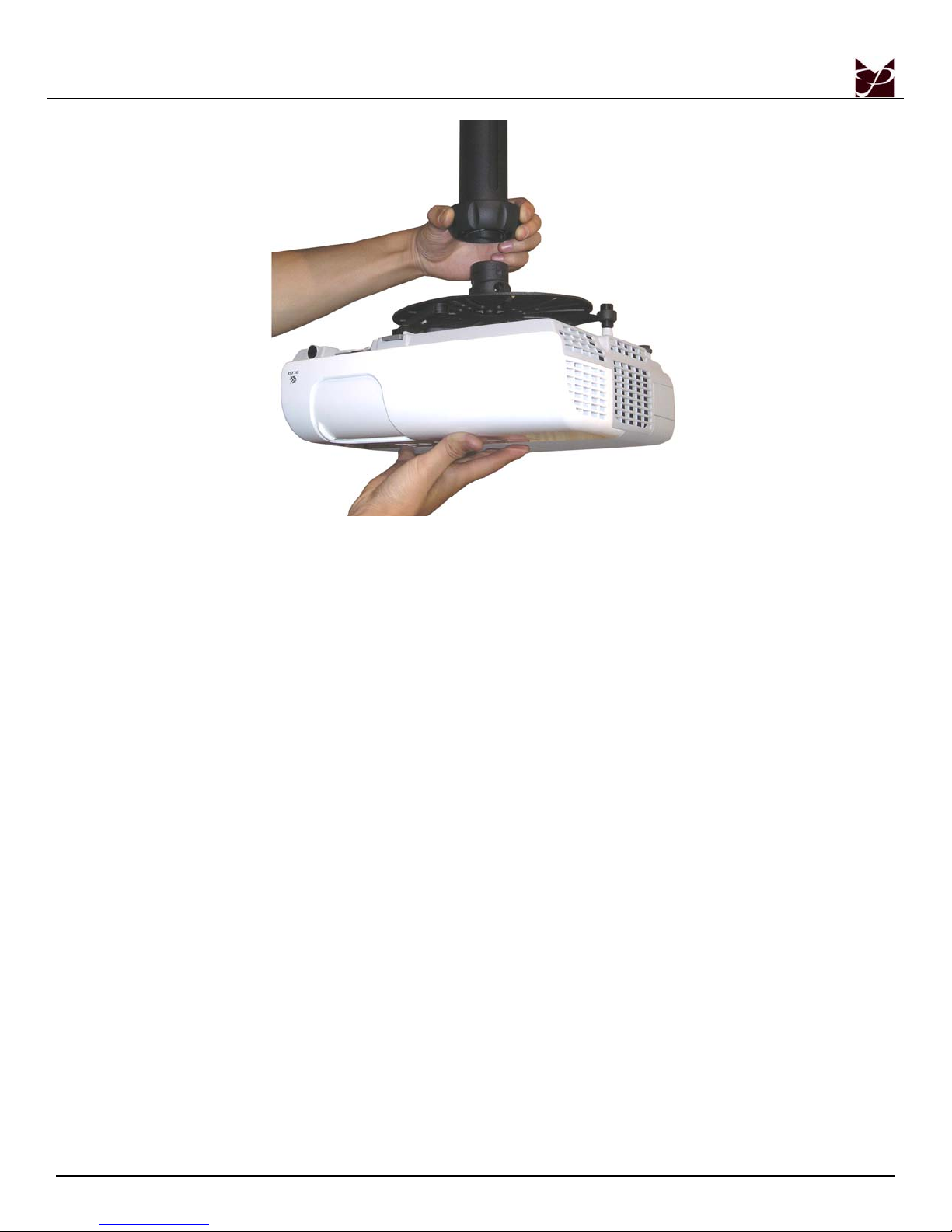
3. Once the SpiroLock™ Assembly is separated, place the projector on a soft flat surface.
Page - 12 - Installation Manual
Page 13
NOVA-EXT
Height Adjustment
M5 Allen Wrench
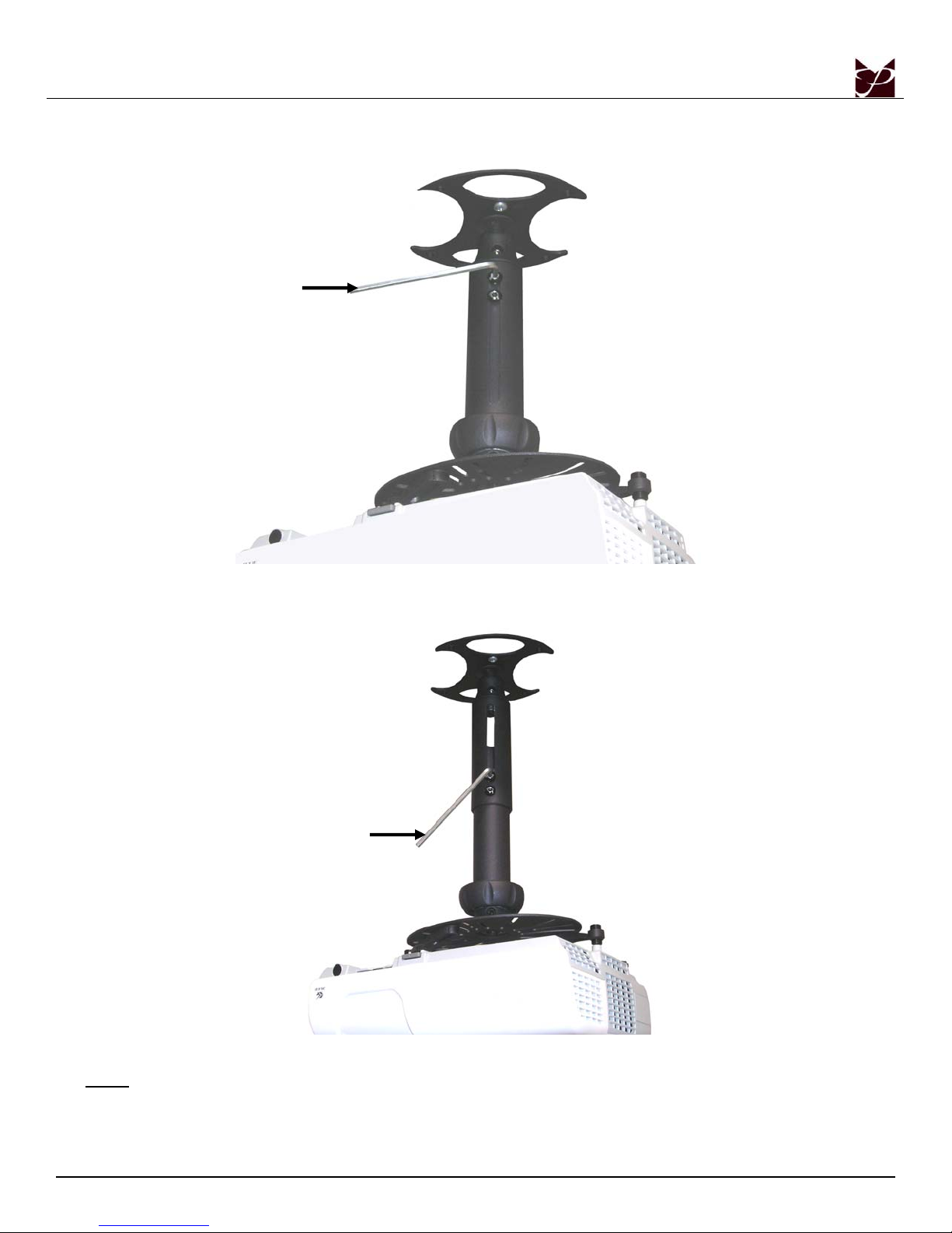
1. To adjust the height of the NOVA-EXT, hold the weight of the projector and loosen the two (2) M8 x 12mm security screws.
M5 Allen Wrench
2. Slide the adjustable suspension neck into the desired position.
3. Re-tighten the two (2) M8 x 12m m security screws.
NOTE
: Do not release the projector until the M8 screws are completely tight.
Installation Manual Page - 13 -
Page 14
NOVA-EXT
Optional Mounting Configurations
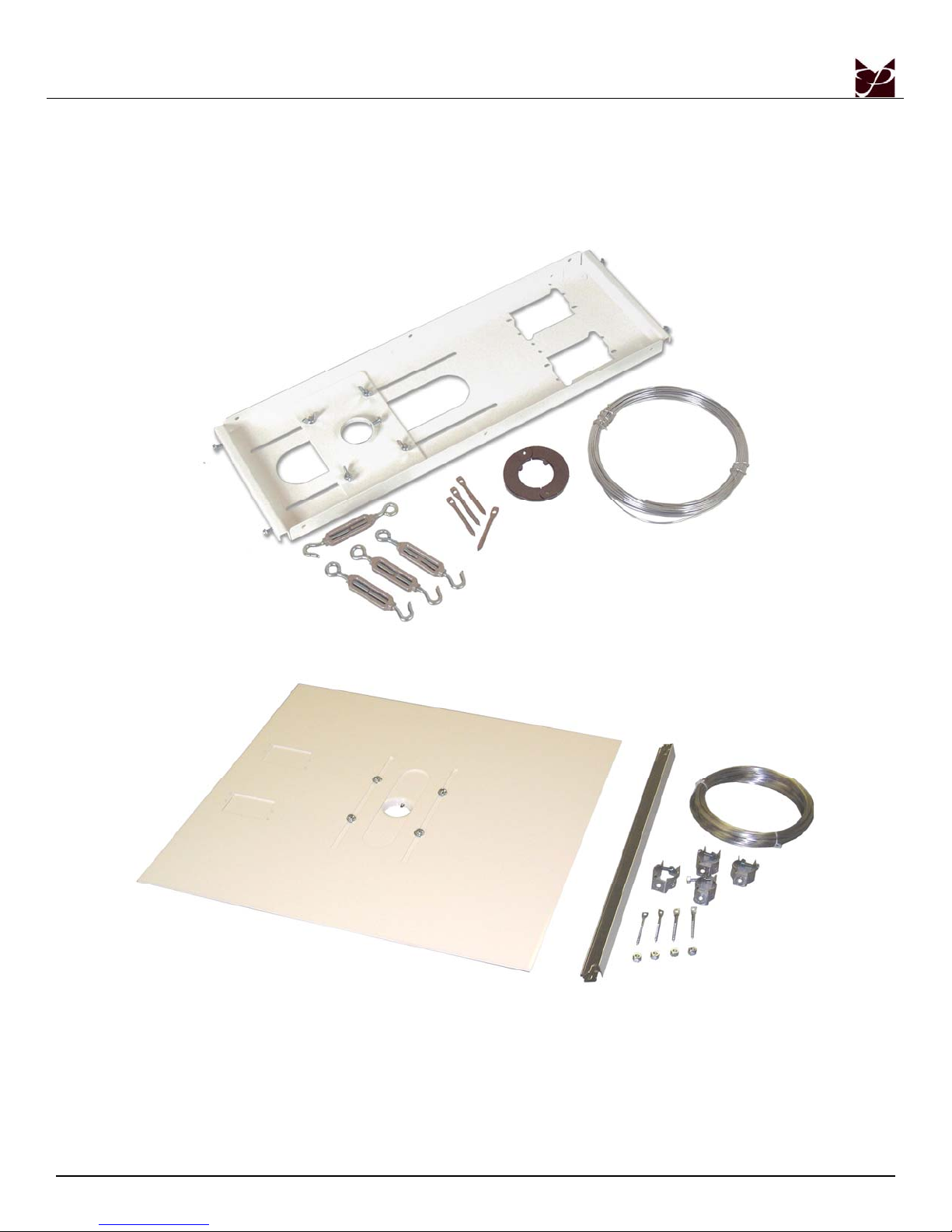
You may use the NOVA-EXT with the following optional accessories. Please refer the Installation Instructions
that come packaged with the following products.
PP-FCTA
PP-FCMA
Page - 14 - Installation Manual
Page 15
NOVA-EXT
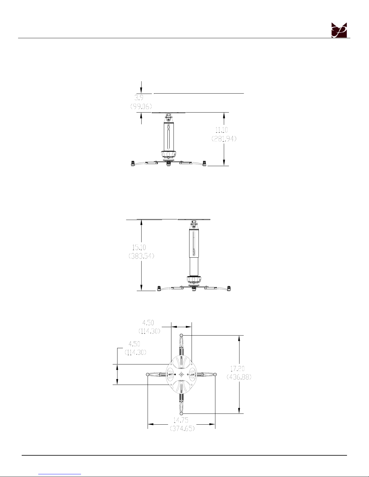
Technical Specifications
All measurements are inches (mm).
Installation Manual Page - 15 -
Page 16

NOVA-EXT
Warranty
PREMIER MOUNTS
LIMITED LIFETIME WARRANTY
What and Who is Covered by this Limited Warranty and for How Long
Premier Mounts warrants this product to be free from defects in material and workmanship for the lifetime of
the original owner of this product. The limited warranty is valid only for the original purchaser of the product.
What Premier Mounts Will Do
At the sole option of Premier Mounts, Premier Mounts will repair or replace any product or product part that is
defective. If Premier Mounts chooses to replace a defective product or part, a replacement product or part will
be shipped to you at no charge, but you must pay any labor costs.
What is Not Covered; Limitations
PREMIER MOUNTS DISCLAIMS ANY LIABILITY FOR DAMAGE TO MOUNTS, ADAPTERS,
DISPLAYS, PROJECTORS, OTHER PROPERTY, OR PERSONAL INJURY RESULTING, IN
WHOLE OR IN PART, FROM IMPROPER INSTALLATION, MODIFICATION, USE OR MISUSE
OF ITS PRODUCTS.
PREMIER MOUNTS DISCLAIMS ALL OTHER WARRANTIES, EXPRESS OR IMPLIED,
INCLUDING WARRANTIES OF MERCHANTABILITY AND FITNESS FOR A PARTICULAR
PURPOSE. PREMIER MOUNTS IS NOT RESPONSIBLE FOR INCIDENTAL OR
CONSEQUENTIAL DAMAGES, INCLUDING BUT NOT LIMITED TO, INABILITY TO USE ITS
PRODUCTS OR LABOR COSTS FOR REMOVING AND REPLACING DEFECTIVE PRODUCTS
OR PARTS. SOME STATES DO NOT ALLOW THE EXCLUSION OR LIMITATION OF
INCIDENTAL OR CONSEQUENTIAL DAMAGES, SO THE ABOVE LIMITATION OR
EXCLUSION MAY NOT APPLY TO YOU.
What Customers Must Do for Limited Warranty Service
If you discover a problem that you think may be covered by the warranty you MUST REPORT it in writing to
the address below within thirty (30) days. Proof of purchase (an original sales receipt) from the original
consumer purchaser must accompany all warranty claims. Warranty claims must also include a description of
the problem, the purchaser’s name, address, and telephone number. General inquiries can be addressed to
Premier Mounts Customer Service at 1-800-368-9700. Warranty claims will not be accepted over the phone or
by fax.
Premier Mounts
Attn: Warranty Claim
3130 E. Miraloma Avenue
Anaheim, CA 92806
How State Law Applies
THIS WARRANTY GIVES YOU SPECIFIC LEGAL RIGHTS, AND YOU MAY ALSO HAVE
OTHER RIGHTS WHICH VARY FROM STATE TO STATE.
Page - 16 - Installation Manual
 Loading...