

Page 1
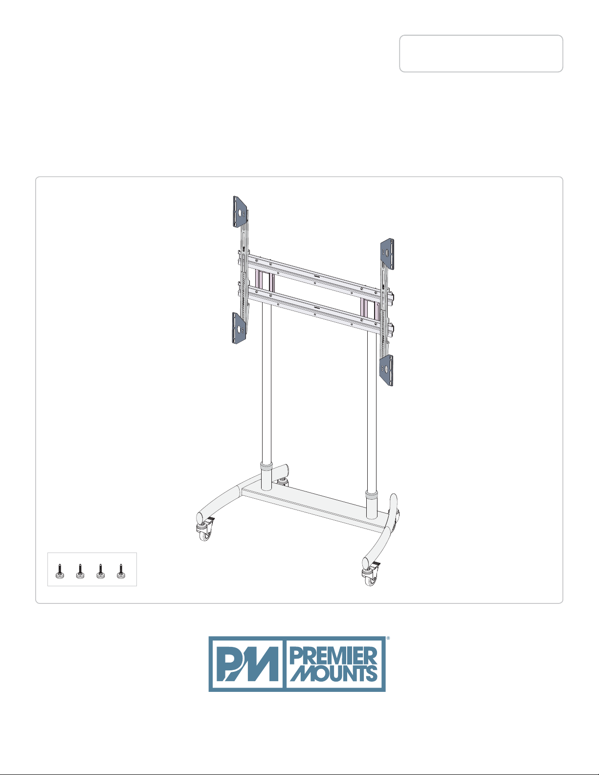
LFC-L / LFC-LB
INSTALLATION GUIDE
Large Format Cart up to
300lbs/136kg Flat Panel Display
Maximum Flat Panel Weight:
300 lb. / 136 kg.
Leveling Feet Option
premiermounts.com | p. 800.368.9700 | e. [email protected]
500 W Central Ave, Suite A, Brea, CA 92821 USA
95003 95 v1.1
pub l. 0 5/29/20
Page 2
LFC-L / LFC-LB
Installation Guide
Maximum Weight Capacity: 300 lbs.
PREMIER MOUNTS DOES NOT WARRANT AGAINST DAMAGE CAUSED BY THE USE OF ANY PREMIER MOUNTS
PRODUCT FOR PURPOSES OTHER THAN THOSE FOR WHICH IT WAS DESIGNED OR DAMAGE CAUSED BY
UNAUTHORIZE ATTACHMENTS OR MODIFICATIONS, AND IS NOT RESPONSIBLE FOR ANY DAMAGES, CLAIMS,
DEMANDS, SUIT ACTIONS OR CAUSES OF ACTION OF WHATEVER KIND RESULTING FROM, ARISING OUT OF OR IN
ANY MANNER RELATING TO ANY SUCH USE, ATTACHMENTS OR MODIFICATIONS.
THE FLOOR MUST BE CAPABLE OF SUPPORTING AT LEAST 300 LBS. IF NOT; THE FLOOR STRUCTURE MUST BE
REINFORCED. PROPER INSTALLATION PROCEDURE BY A QUALIFIED SERVICE TECHNICIAN, AS OUTLINED IN THE
INSTLLATION INSTRUCTIONS, MUST BE ADHERED TO. FAILURE TO DO SO COULD RESULT IN SERIOUS PERSONAL
INJURY, OR EVEN DEATH.
SAFETY MEASURES MUST BE PRACTICED AT ALL TIMES DURING THE ASSEMBLY F THIS PRODUCT. USE PROPER
SAFETY GEAR AND TOOLS FOR THE ASSEMBLY PROCEDURE TO PREVENT PERSONAL INJURY.
PRIOR TO THE INSTALLATION OF THIS PRODUCT, THE ASSEMBLY INSTRUCTIONS SHOULD BE READ AND
COMPLETELY UNDERSTOOD. THE ASSEMBLY INSTRUCTIONS MUST BE READ TO PREVENT PERSONAL INJURY
AND PROPERTY DAMAGE. KEEP THESE ASSEMBLY INSTRUCTIONS IN AN EASILY ACCESSIBLE LOCATOIN FOR
FUTURE REFERENCE.
CAUTION STATEMENT
Do not install on a structure that is prone to vibration, movement or chance of impact. Failure to do so could result in damage
to the plasma display and/or damage to the mounting surface.
mishandling the display.
Page 2
premiermounts.com | p. 800.368.9700 | e. [email protected]premiermounts.com | p. 800.368.9700 | e. [email protected]
Page 3
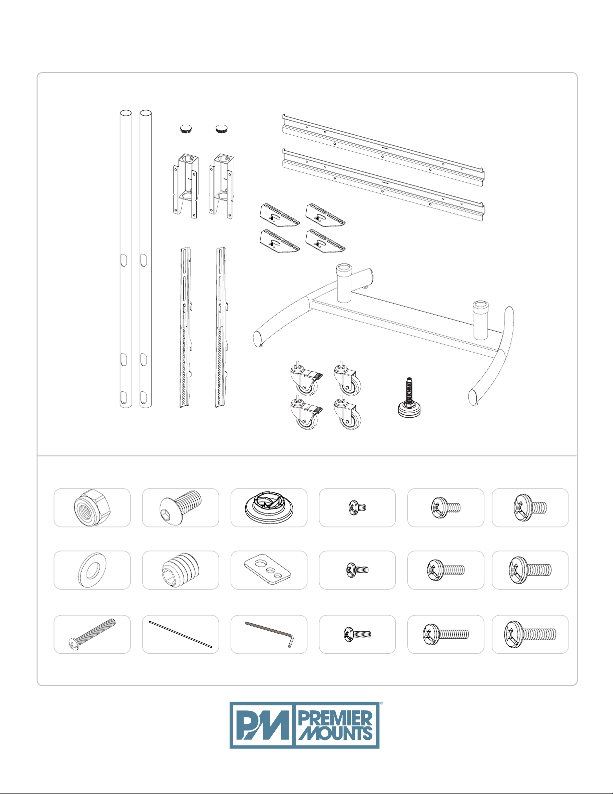
CORE COMPONENTS:
LFC-L / LFC-LB
Installation Guide
INSTALLATION HARDWARE:
M8 Lock Nut
(Qty 4)
M8 Washer
(Qty 4)
M6 x 45mm Pan
Head (Qty 4)
M8 x 16mm Button
Hex (Qty 8)
M8 x 12mm Set
Screw (Qty 8)
Thread Depth
Indicator (Qty 1)
Universal Spacers
(Qty 8)
Universal Washers
(Qty 4)
M5 & M4 Hex Key
(Qty 1 per)
M4 x 12mm
(Qty 4)
M4 x 16mm
(Qty 4)
M4 x 25mm
(Qty 4)
OR
x4
M6 x 12mm
(Qty 4)
M6 x 16mm
(Qty 4)
M6 x 25mm
(Qty 4)
M8 x 12mm
(Qty 4)
M8 x 16mm
(Qty 4)
M8 x 25mm
(Qty 4)
premiermounts.com | p. 800.368.9700 | e. [email protected]
Page 3
Page 4
NL
NL
L
L
LFC-L / LFC-LB
2
1
Installation Guide
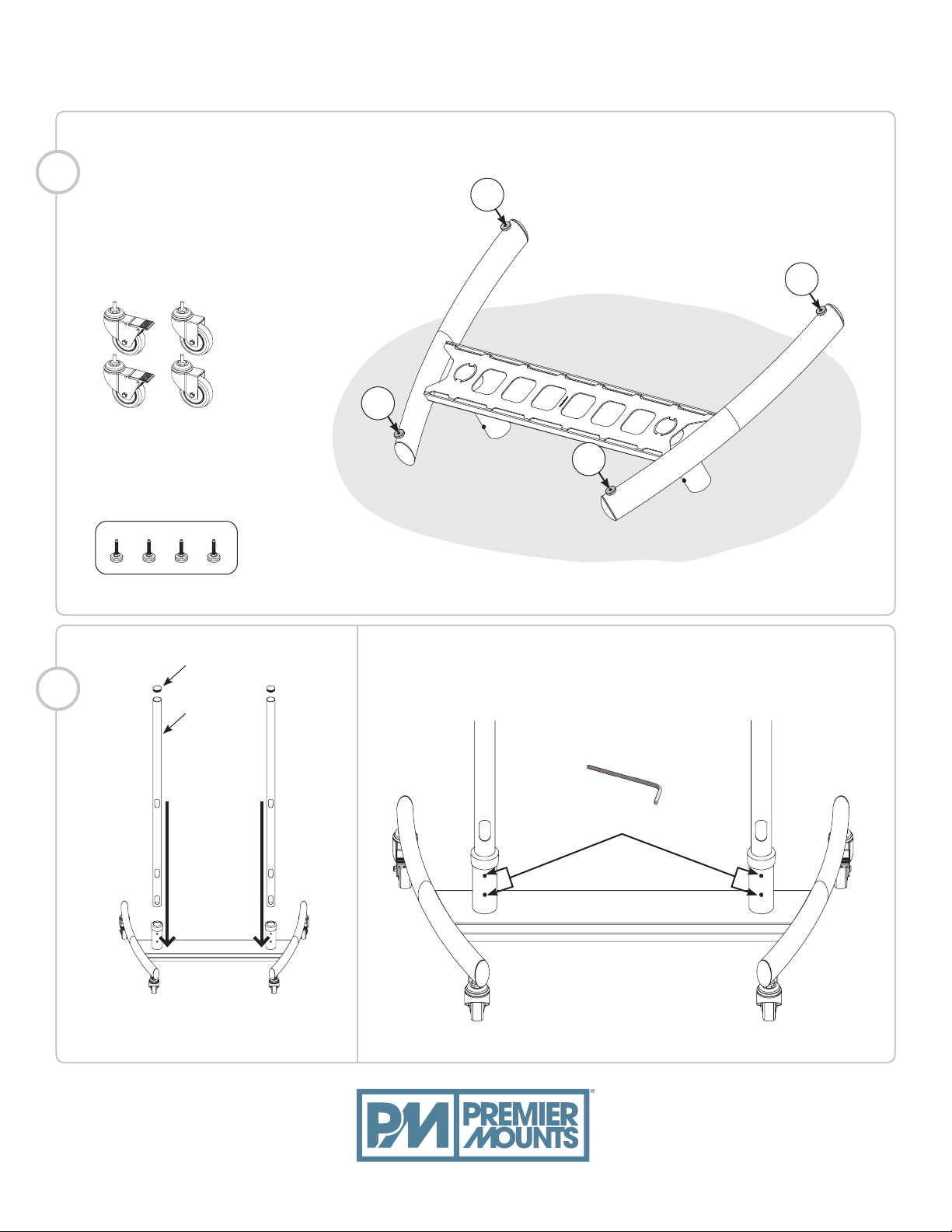
Use 21mm wrench to install a pair of
(L) locking and (NL) non-locking casters
or four leveling feet.
3/8”-16 threaded
casters
OR
Leveling Feet Option
INSTALL THE CASTERS / LEVELING FEET
Sof t Mat
Notes: caster or leveling feet option may vary by model number.
2
Pole plug
Pole 60”
(Cable access facing to the rear)
Insert (4) M8 x 12mm set screws at the location shown below
then tighten using a M4 Hex key.
M4 Hex Key
Page 4
premiermounts.com | p. 800.368.9700 | e. [email protected]
Page 5
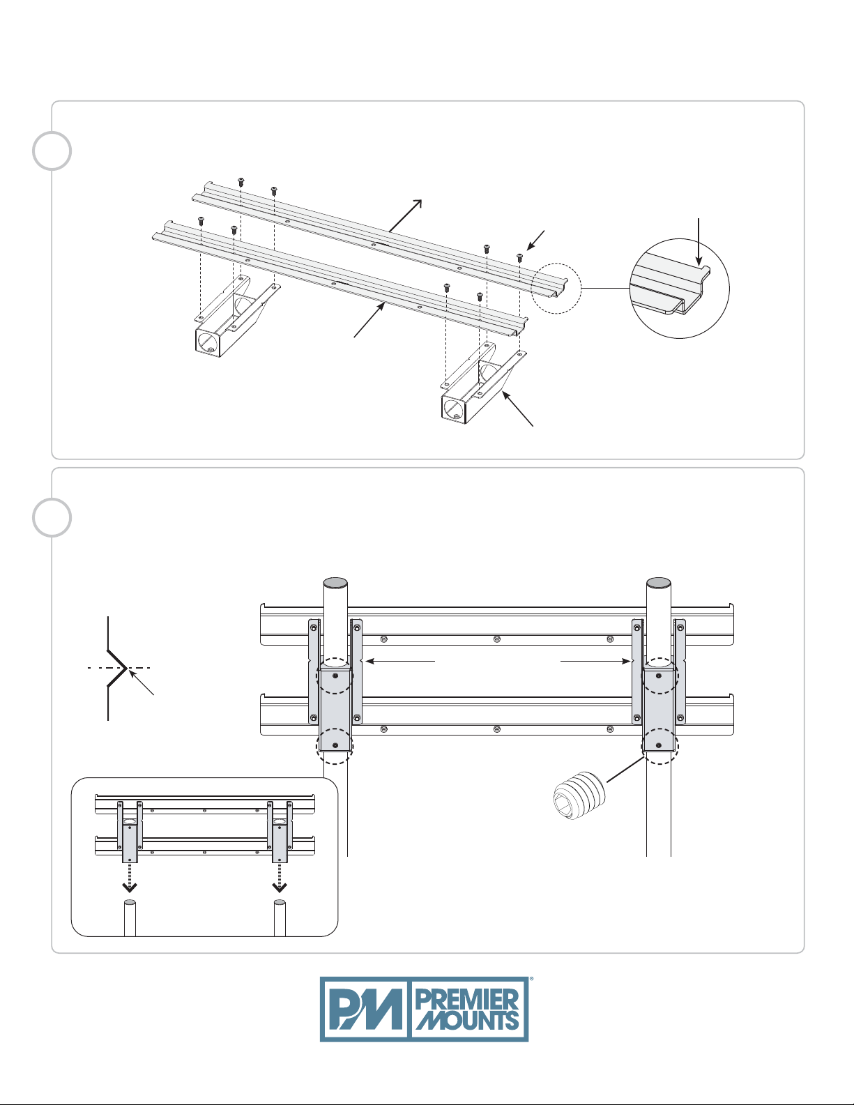
ASSEMBLE THE POLE ADAPTER TOGETHER
3
4
LFC-L / LFC-LB
Installation Guide
Up
(8) M8 x 16mm
Buttton Hex
Vertical Brackets
Pole Adapter
MOUNT THE POLE ADAPTER
Insert (4) M8 x 12mm set screws at the location shown, raise or lower the mount to desired height,
and below then tighten using a M4 Hex key.
Set the tab
pointing up
Center
Viewing
Height
Viewing Height
Center
(4) M8 x 12mm
Set Screw
premiermounts.com | p. 800.368.9700 | e. [email protected]
Page 5
Page 6
LFC-L / LFC-LB
5
Installation Guide
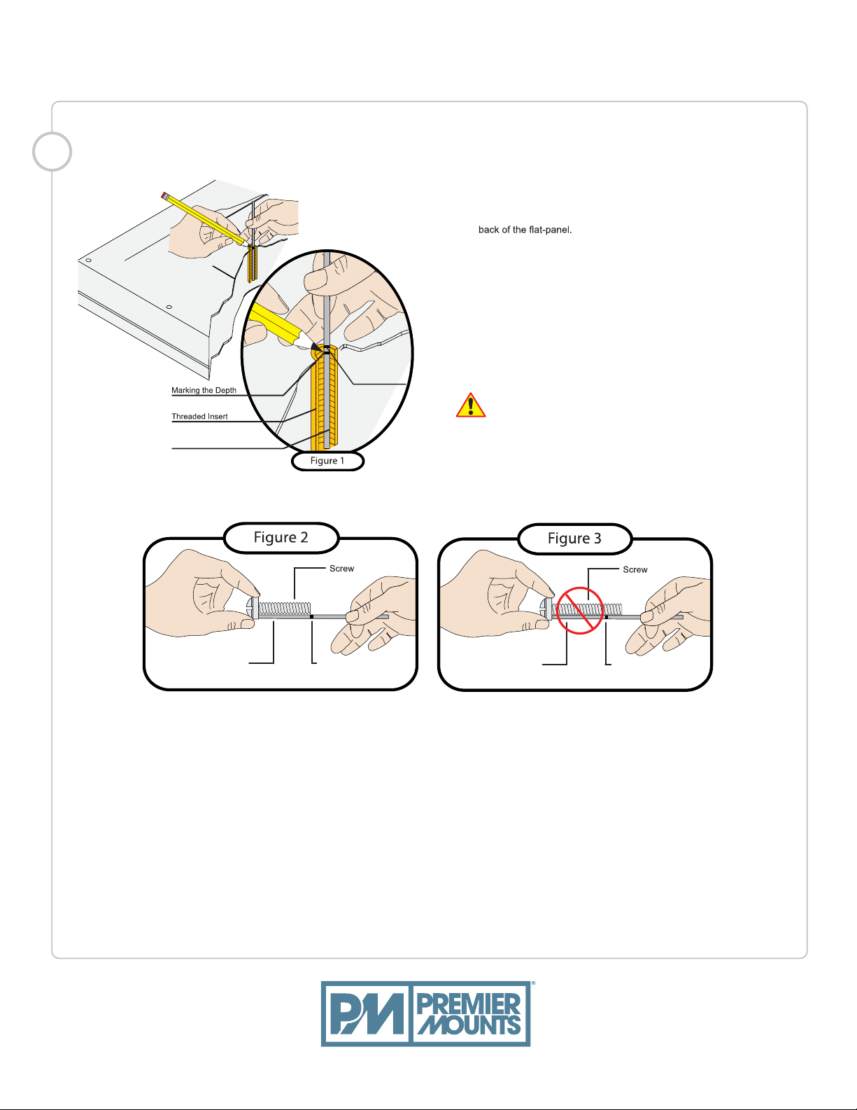
Small Straw or Toothpick
SELECTING THE MOUNTING HARDWARE
1) Insert a small straw or toothpick into the threaded inserts found on the
2) Use a pencil to mark the depth of the threaded insert on the small straw
or toothpick.
3) Mark the straw or toothpick 1/8” above the depth of the threaded insert,
as shown in Figure 1.
4) Insert the small straw or toothpick into the remaining threaded inserts
to compare and verify their depth using the straw or toothpick’s 1/8”
allowance mark.
Marking the 1/8”
Allowance
5) Locate the correct diameter screw for the threaded insert.
If the screw you selected is longer than the 1/8” allowance mark on
the small straw or toothpick, as shown in Figure 2 and Figure 3, do
not use this screw. The screw length must not bypass the mark.
6) Test each size of the screws provided.
The correct screws should thread easily into themounting point and
not pull out when tension is applied.
Page 6
Small Straw
or Toothpick
Depth Plus 1/8” Allowance
Mark
Small Straw
or Toothpick
premiermounts.com | p. 800.368.9700 | e. [email protected]
Depth Plus 1/8” Allowance
Mark
Page 7
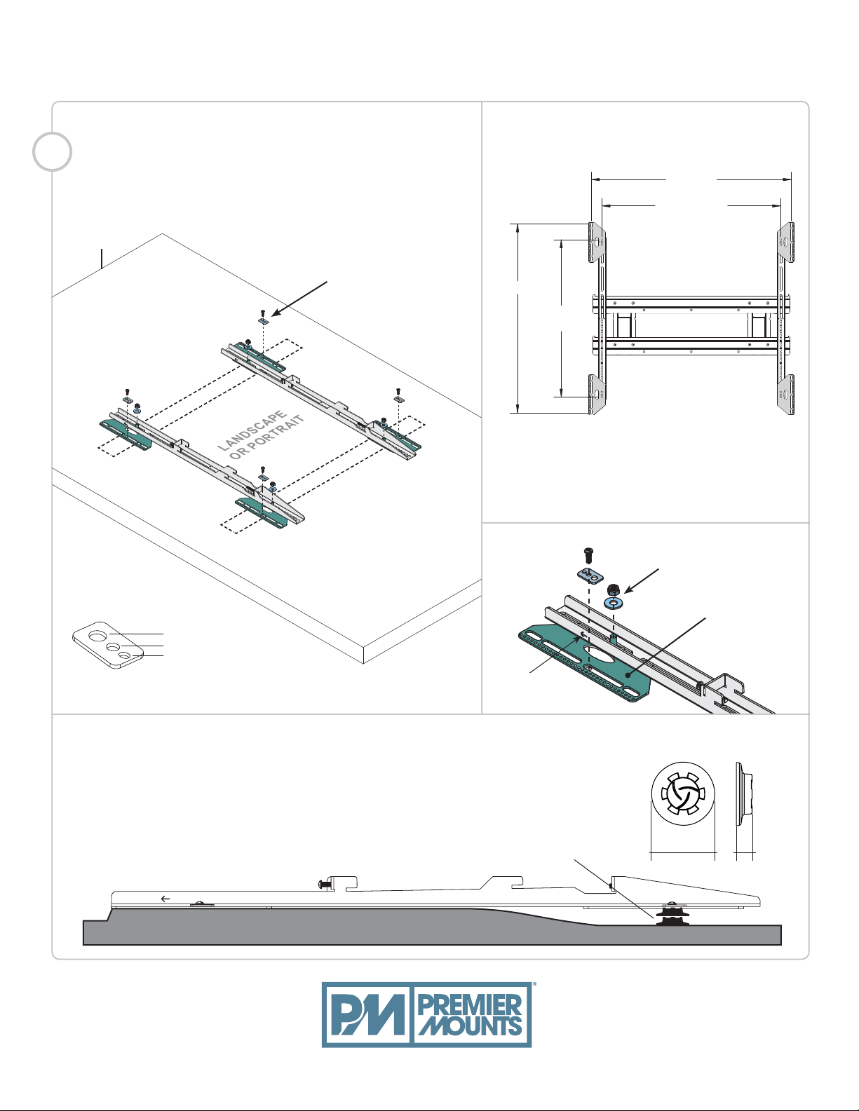
LANDSCAPE
OR PORTRAIT
1019mm
LFC-L / LFC-LB
4
Installation Guide
EXTENSION ADAPTER WINGSINSTALL THE MOUNTING BRACKETS
Top of flat
panel
Selected mounting screws
(from previous step) and
universal washers.
Do not overtighten.
910mm
w/o adapters
964mm
802mm
w/o adapter
Max Mounting Pattern
Install the optional adapter wings
to make accommodations for various
mounting patterns.
(4) M8 Lock Nut
w/ washers
M8
M5, M6
M4
Universal Washers x4
UP Arrow
USE ADDITIONAL UNIVERSAL SPACERS TO FILL UNEVEN GAPS
Universal Spacers allow the user to attach the mounting bracket to flat-panels
which have recessed or uneven mount points. Each Universal Spacer adds 1/4”
to the distance between the mounting bracket and the flat-panel.
Recessed or uneven
mounting points
(4) Adapter
Wings
1˝ ¼˝
premiermounts.com | p. 800.368.9700 | e. [email protected]
Page 7
Page 8
LFC-L / LFC-LB
7
Installation Guide
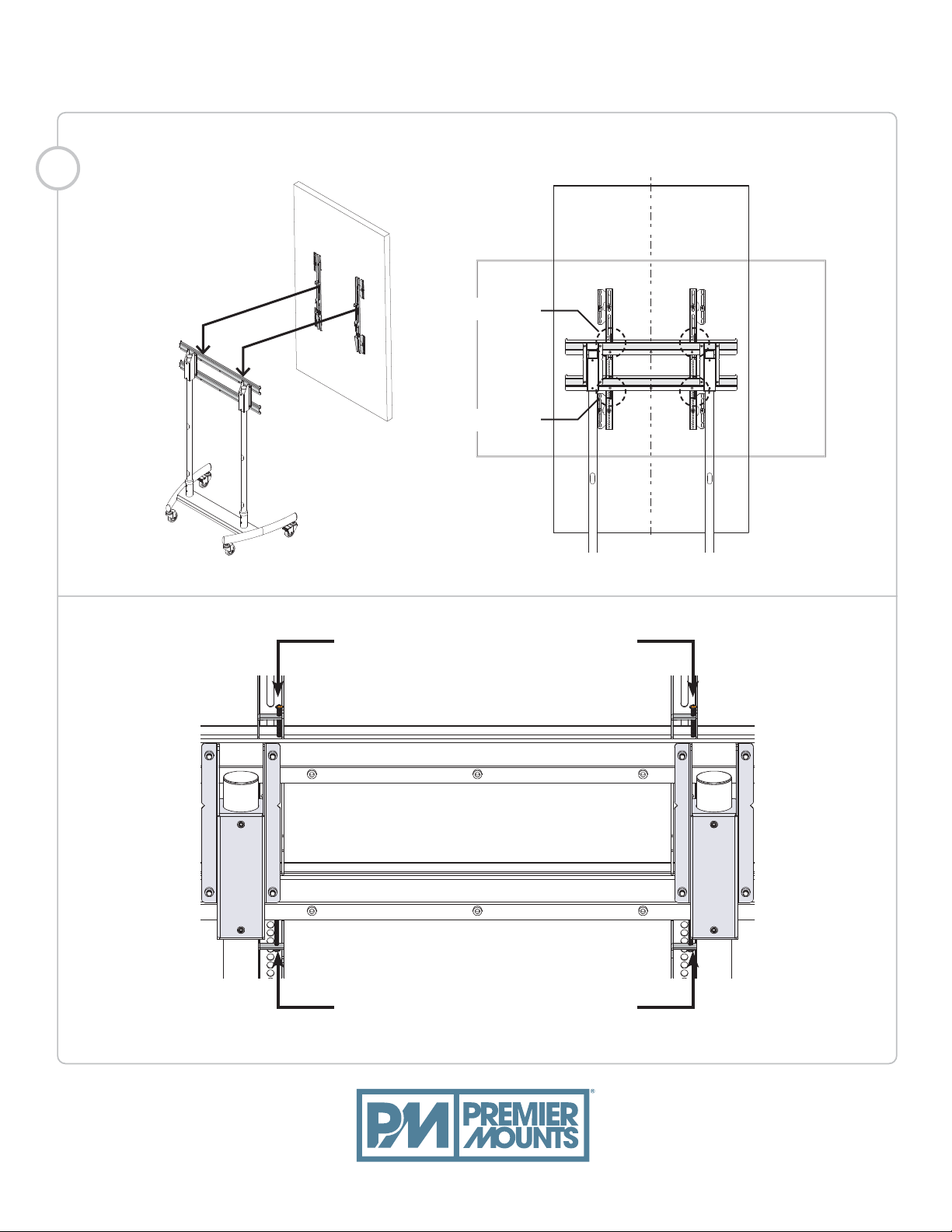
MOUNT THE FLAT-PANEL DISPLAY AND CENTER THE MOUNT
Post-Level
Locking
STEP 1:
Tighten/loosen the (2) M6 x 45mm
screws for post-leveling adjustment.
STEP 2:
Install (2) M6 x 45mm screws to securely
lock the mount firmly in place.
CL
Page 8
premiermounts.com | p. 800.368.9700 | e. [email protected]
Page 9
44.94
1141.47
OD
LFC-L / LFC-LB
Installation Guide
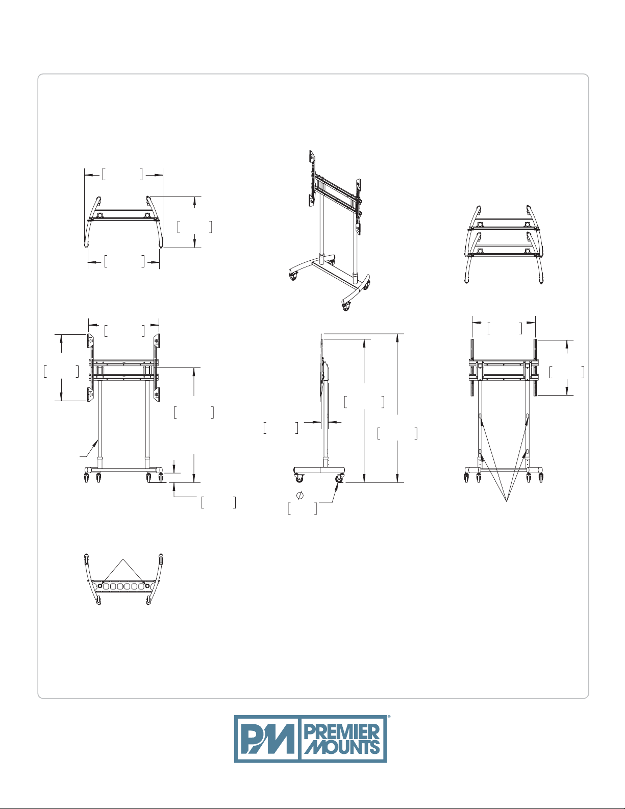
PRODUCT DIMENSION
(NESTING CAPABILITY)
37.94
963.57
TUBES
2" OD
28.98
736.20
41.00
1041.48
ID
40.11
1018.77
65.37
1660.40
MAX CENTER
VIEWING HEIGHT
WITH CASTERS
5.30
134.49
35.84
910.31
81.66
2074.13
102.63
4.04
4
99.57
84.72
2151.85
CABLE ROUTE PATHS
31.58
802.15
CABLE ROUTE
PATHS
premiermounts.com | p. 800.368.9700 | e. [email protected]
Page 9
Page 10

PREMIER MOUNTS
LIMITED LIFETIME WARRANTY
What and Who is Covered by this Limited Lifetime Warranty
Premier Mounts warrants all mounting products to be free from defects in material and workmanship for the
lifetime of the original installation of the product.
What Premier Mounts Will Do
At the sole option of Premier Mounts, Premier Mounts will repair or replace any product or product part that is
defective. If Premier Mounts chooses to replace a defective product or part, a replacement product or part will
be shipped to you at no charge, but you must pay any related labor costs.
What is Not Covered: Limitations
Premier Mounts disclaims any liability for damage to mounts, adapters, displays, projectors, other property,
products.
NOTWITHSTANDING ANYTHING TO THE CONTRARY IN THIS WARRANTY, THIS WARRANTY IS
LIMITED TO FIVE YEARS FROM THE DATE OF PURCHASE IN THE EVENT THAT THE WARRANTED PRODUCT IS COMMERCIALLY RENTED OUT.
electrical items, are backed by a 3-year warranty.
Premier Mounts disclaims all other warranties, express or implied, including warranties of merchantability and
including but not limited to, inability to use its products or labor costs for removing and replacing defective
products or parts. Some states do not allow the exclusion or limitation of incidental or consequential damages,
so the above limitation or exclusion may not apply to you.
What Customers Must Do for Warranty Service
If you discover a problem that you think may be covered by the warranty, you must report it in writing to the
address below within thirty (30) days. Proof of purchase (an original sales receipt) from the original consumer
purchaser must accompany all warranty claims. Warranty claims must also include a description of the problem,
the purchaser’s name, address, and telephone number. General inquiries can be addressed to Premier Mounts
Customer Service at 1-800-368-9700. Warranty claims will not be accepted over the phone or by fax.
PREMIER MOUNTS
ATTN: Warrenty Claims
500 W Central Ave, Suite A
Brea, CA 92821
How State Law Applies
Premier Mounts intends to make this manual accurate and complete. However, Premier Mounts makes no claim that the information contained herein covers all details,
conditions or variations, nor does it provide for every possible contingency in connection with the installation or use of this product. The information contained in this
document is subject to change without notice or obligation of any kind. Premier Mounts makes no representation of warranty, expressed or implied, regarding the
information contained herein. Premier Mounts assumes no responsibility for accuracy
PREMIER MOUNTS
©
500 W Central Ave, Suite A
Brea, CA 92821
USA & CANADA
Phone: 800-368-9700
Fax: 800-832-4888
 Loading...