

Page 1

I N S T A L L A T I O N M A N U A L
Inwall mount
3130 E. Miraloma Ave. Anaheim, CA 92806 Phone: 800 368-9700 Fax: 800 832-4888
www.mounts.com
PREMIER MOUNTS ©2004/ REV 00
Page 2
The wall structure should be capable of supporting a weight of at least five (5) times the display’s weight. If it cannot the wall must be
reinforced. Proper installation procedure by qualified personnel as outlined in the installations instructions must be adhered to. Failure to do
so could result in serious personal injury.
WARNING: Safety precaution measures must be practiced at all times during the installation of this product. Use proper safety gear and
tools for the installation procedure to prevent personal injury.
The entire installation instructions should be fully read and understood, including all of the safety symbols and safety precautions, before
beginning installation. The installation instructions should be read, understood and followed to prevent personal injury or property damage.
Keep these installation instructions in an easily accessible location for future reference.
Indicates that the power plug is to be disconnected from
the power outlet.
Contact Premier Mounts for any questions
Safety precautions must be taken at all times.
Warning and caution in general
A secured structure wooden stud wall must always support the weight or load of the display. Always confirm the wood stud before
beginning the installation.
Do not install in locations where there is vibration, movement or danger of impact. Failure to do so could result in display cracking or
falling from the wall causing damage and injury.
Do not install near heater, fireplace, direct sunlight or air conditioning or any other source of direct heat energy. Failure to do so may
result in damage to the display and could cause a risk of fire.
At least two qualified people should always perform the installation work. Injury and damage can result from dropping or mishandling
the display.
- 2 -
Page 3
(
)
A
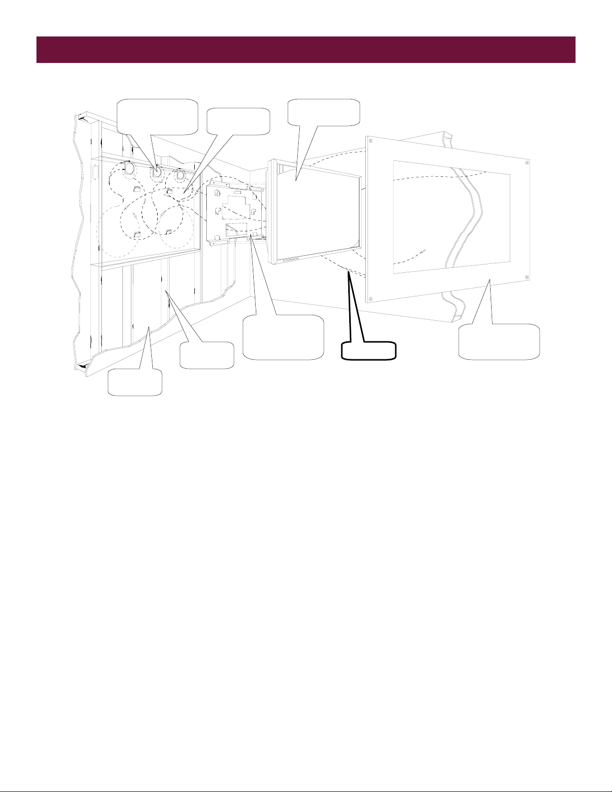
Assembly drawing
Fan brackets
(1 supplied with
inwall
In-wall plenum
box
Display
not supplied)
Wall
structure
Wood stud
frame
Mounting
Bracket
(Sold separately)
ir flow
Decorative bezel
provided by
customer
- 3 -
Page 4

Parts list
All of these parts are used to install the mounting bracket. Make sure that none of these parts are missing before beginning installation. If there
are parts missing stop the installation and contact Premier Mounts.
INW42 Plenum
INW50 Plenum
INW60 Plenum
(4) 6/32” Hex nuts
(1) Muffin fan
(3) 10/32” Kep nuts
(1) Muffin fan
bracket
(4) 6/32” Phillips
screws
- 4 -
Page 5

pp
pp
pp
Opening the wall structure
NOTE: It is assumed that the room ambient air temperature and conditions where the INW-series is to be incorporated is suitable to maintain an acceptable
operating temperature for the display. It should also be noted that due to the shear size and weight of the large screen display when attached to the base pan it
will have a natural slight down tilt characteristic to about 3°. Raising the initial installation height of the pan or setting the base pan on a slight reverse angle will
compensate for this. The mount that any display will protrude beyond a standard depth wall varies depending on the display chassis depth and rear ventilation
path clearance requirements.
INW42 Series
Prior to cutting, survey the wall that is to receive the plenum base pan to ensure the area to be cut into is free of obstructions such as cables, wire pipes etc.
The base pan requires a wood frame or other suitable material to support a weight of at least 300 lbs. with a width opening of 46.375” minimum and a height
opening of 34.062” minimum and a wood stud depth of 3.50” minimum. See figure 1.
NOTE: The plenum base pan width of 46.38” is such that it will fit directly inside the first and forth 16.000” center wood stud in a standard framed wall
licable in the location selection.
if a
INW50 Series
Prior to cutting, survey the wall that is to receive the plenum base pan to ensure the area to be cut into is free of obstructions such as cables, wire pipes etc.
The base pan requires a wood frame or other suitable material to support a weight of at least 300 lbs. with a width opening of 52.875” minimum and a height
opening of 36.750” minimum and a wood stud depth of 3.50” minimum. See figure 1.
NOTE: The plenum base pan width of 52.750” is such that it will fit directly inside the first and forth 16.000” center wood stud in a standard framed
wall if a
licable in the location selection.
INW60 Series
Prior to cutting, survey the wall that is to receive the plenum base pan to ensure the area to be cut into is free of obstructions such as cables, wire pipes etc.
The base pan requires a wood frame or other suitable material to support a weight of at least 300 lbs. with a width opening of 64.250” minimum and a height
opening of 44.750” minimum and a wood stud depth of 3.50” minimum. See figure 1.
NOTE: The plenum base pan width of 64.00” is such that it will fit directly inside the first and forth 16.000” center wood stud in a standard framed wall
licable in the location selection.
if a
Figure 1
Wall structure
Wood stud frame
Wood studs
- 5 -
Page 6
p
Step 2
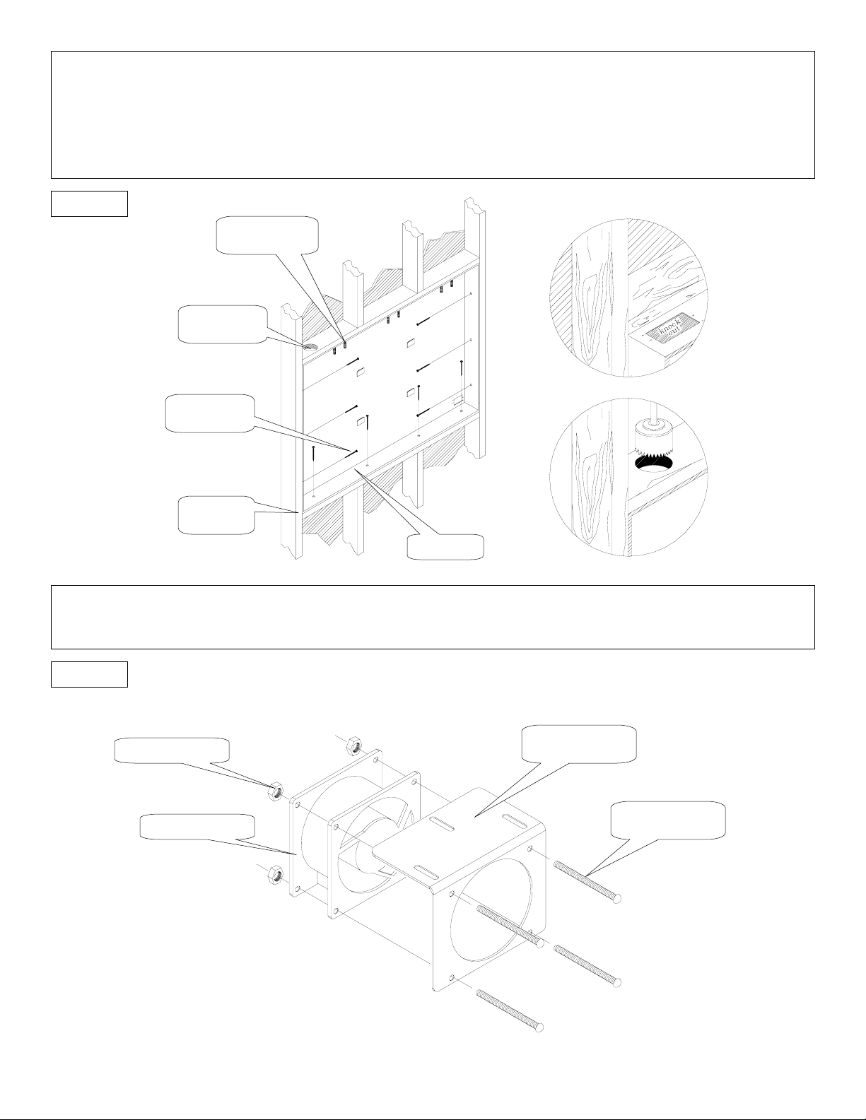
Partial “knock outs” are incorporated in the top and upper back on both sides of the base pan for bringing power and signal cables into the pan in accordance
with code. Insert the pan fully (in the case of a standard 2 x 4-stud wall) or to the desired depth in a deeper wall structure. Secure the pan to the wood stud frame
using nails or wood screws (commercially available). See figure 2.
NOTE: A standard “handy box” extension ring can mount directly to the inside of the pan at the knock out points to provide an A/C power duplex
outlet mounting point.
Figure 2
Mounting studs
for the fan bracket
Cable access
hole
Nails or wood
screws
Wood stud
frame
Plenum
Step 3
Install the muffin fan to the mounting bracket (refer to the muffin fan manual for air flow position). Secure the muffin fan with the four (4) 6/32” hex nuts and
Phillips screws (supplied) See figure 3.
Figure 3
(4) 6/32” Hex nuts
Muffin fan mounting
bracket
Muffin fan
(4) 6/32”x 2”
s screws
Philli
- 6 -
Page 7
p
Step 4
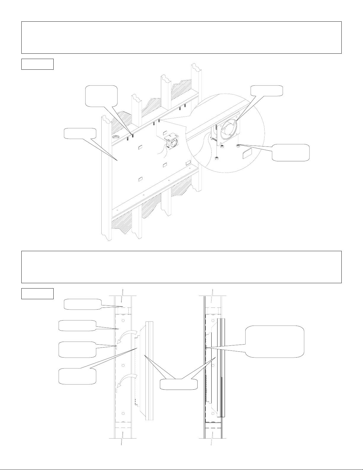
Install the ventilation assist fan (if used) on one of the three 10/32” thread mounting points in the top of the base pan with the three 10/32” nuts supplied.
The fan supplied uses 110-volts A/C current and comes with “pig tail” ends. It is recommended the fan be wired to the same 110-volt A/C switch leg as the
feeding power to the display. This will insure the operation during all times when the display is on. Install all power and signal interface cables. See figure 4.
Figure 4
Muffin fan
bracket
studs
Muffin fan
Plenum
(3) 10/32” Hex
nuts
Step 5
Install the mount to the rear of the display with the mounting hardware supplied. Lift the display and mount assembly (minimum two people recommended) and
secure to the base pan by allowing the mount tabs to be inserted fully into and down the receiving slots on the back of the plenum. See figure 5. Decorate the
front of the Plenum per customer request.
Figure 5
Wall structure
Plenum
Receiving tabs
lenum
on the
Caution: All four (4) tabs
must be fully inserted to
the receiving tabs before
letting go of the display.
Mounting
bracket
Display
- 7 -
 Loading...