

Page 1
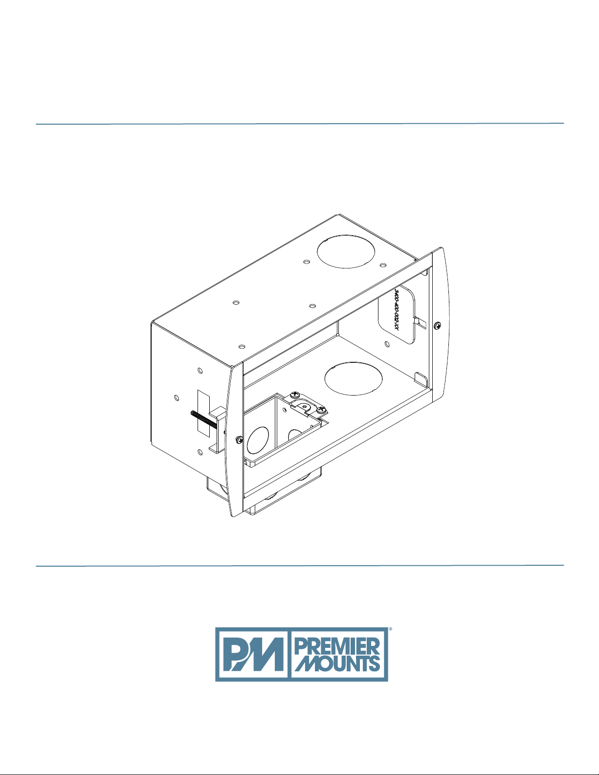
GB-INWAVP
Gear Box In-Wall Audio / Video / Power Mount
INSTALLATION INSTRUCTIONS
premiermounts.com | p. 800.368.9700 | e. [email protected]
500 W Central Ave, Suite A, Brea, CA 92821 USA
9534-004-011-01
Page 2
GB-INWAVP
Contents
Weight Limit. ............................................................................................................................................................. 2
Warning Statements. ................................................................................................................................................ 2
Installation Tools. ...................................................................................................................................................... 3
Parts List................................................................................................................................................................... 3
Features. .................................................................................................................................................................. 4
Introduction. .............................................................................................................................................................. 5
Drywall Installation.................................................................................................................................................... 5
Wood Stud Installation (Optional). ............................................................................................................................ 8
Outlet Box Installation............................................................................................................................................. 10
Installing the Cable Bushings. ................................................................................................................................ 11
Technical Speci cations. ........................................................................................................................................ 11
Warranty. ................................................................................................................................................................ 12
Weight Limit
THIS PRODUCT IS NOT INTENDED TO SUPPORT
Maximum Weight:
THE WEIGHT OF ANY PRODUCTS OTHER THAN THE
NECESSARY CONNECTIONS FOR WHICH IT WAS
DESIGNED.
Warning Statements
PRIOR TO THE INSTALLATION OF THIS PRODUCT, THE INSTALLATION INSTRUCTIONS MUST BE READ AND
COMPLETELY UNDERSTOOD. KEEP THESE INSTALLATION INSTRUCTIONS IN AN EASILY ACCESSIBLE LOCATION
FOR FUTURE REFERENCE.
PROPER INSTALLATION PROCEDURE BY A QUALIFIED SERVICE TECHNICIAN MUST BE FOLLOWED, AS OUTLINED
IN THESE INSTALLATION INSTRUCTIONS. FAILURE TO DO SO COULD RESULT IN PROPERTY DAMAGE, SERIOUS
PERSONAL INJURY, OR EVEN DEATH.
SAFETY MEASURES MUST BE PRACTICED AT ALL TIMES DURING THE ASSEMBLY OF THIS PRODUCT. USE
PROPER SAFETY EQUIPMENT AND TOOLS FOR THE ASSEMBLY PROCEDURE TO PREVENT PERSONAL INJURY.
PREMIER MOUNTS DOES NOT WARRANT AGAINST DAMAGE CAUSED BY THE USE OF ANY PREMIER MOUNTS
PRODUCT FOR PURPOSES OTHER THAN THOSE FOR WHICH IT WAS DESIGNED OR DAMAGE CAUSED BY
UNAUTHORIZED ATTACHMENTS OR MODIFICATIONS, AND IS NOT RESPONSIBLE FOR ANY DAMAGES, CLAIMS,
DEMANDS, SUITS, ACTIONS OR CAUSES OF ACTION OF WHATEVER KIND RESULTING FROM, ARISING OUT OF OR
IN ANY MANNER RELATING TO ANY SUCH USE, ATTACHMENTS OR MODIFICATIONS.
If mounting to wall studs or ceiling joists, make sure that the mounting screws are anchored into the center of the wall studs
or ceiling joists. Use of an edge-to-edge stud nder is recommended.
Be aware of the mounting environment. If drilling and/or cutting into the mounting surface, always make sure that there
are no electrical wires in wall. Cutting or drilling into an electrical line may cause serious personal injury.
Make sure there are no water or natural gas lines inside the wall where the mount is to be located. Cutting or drilling into a
water or gas line may cause severe property damage or personal injury.
This product is intended for indoor use only. Use of this product outdoors could lead to product failure and/or serious
personal injury.
Page 2
premiermounts.com | p. 800.368.9700 | e. [email protected]premiermounts.com | p. 800.368.9700 | e. [email protected]
Visit the Premier Mounts website at http://www.mounts.com Installation Instructions
Page 3
GB-INWAVP
Installation Tools
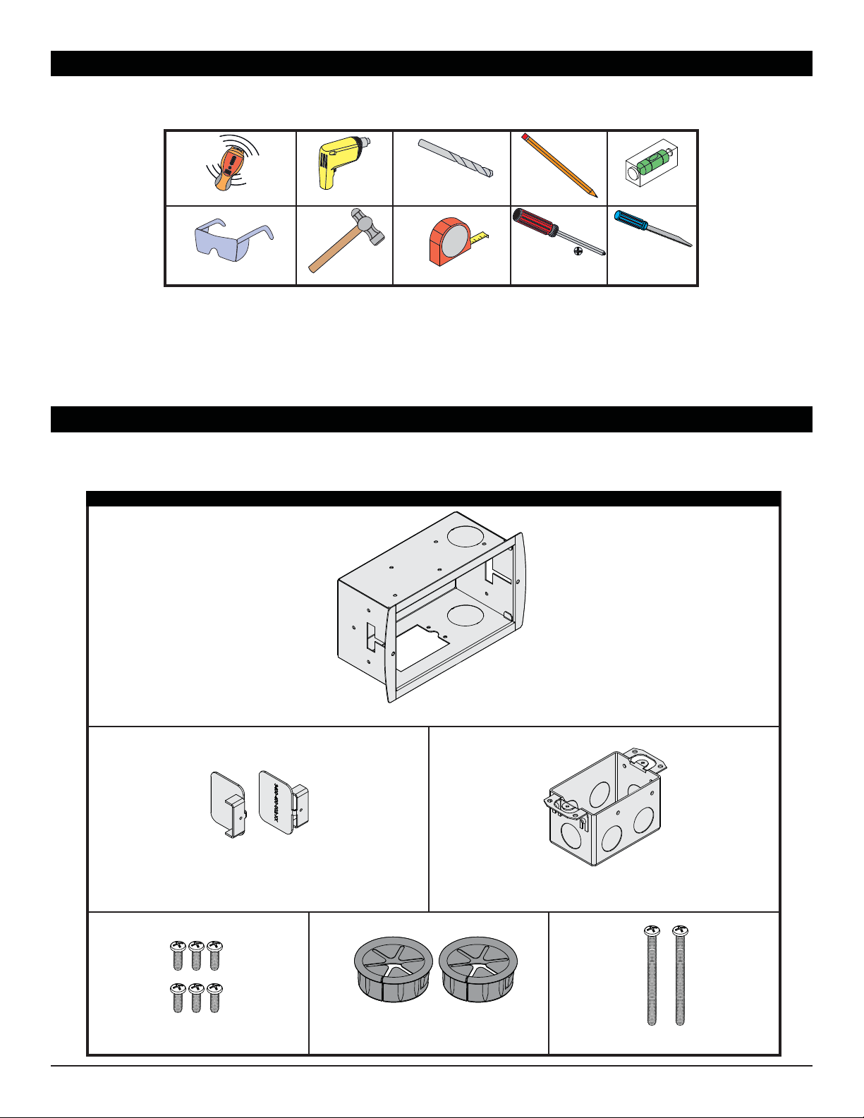
The following tools may be required, dependent upon your particular installation. These tools are not provided by
Premier Mounts, but you can purchase them at your local hardware store.
ǩ Wood
Electronic Stud Finder
Protective Eyewear
Hand Held Drill
Hammer
Drill Bit
Tape Measure
Pencil
Phillips Tip
Screwdriver
Level
Drywall Saw
Parts List
Your Premier Mounts product is shipped with all proper installation hardware and components. Make sure that none
of these parts are missing and/or damaged before beginning installation. If there are parts missing and/or damaged,
please stop the installation and contact Premier Mounts (800) 368-9700.
In-Wall Box Hardware
Installation Instructions
In-Wall Clamp (Qty 2)
premiermounts.com | p. 800.368.9700 | e. [email protected]
Visit Premier Mounts website at http://www.mounts.com Page 3
In-Wall Box (Qty 1)
Outlet Box w/ Knockouts (Qty 1)
6-32 x 2Ǝ Panhead Screw (Qty 2)6-32 x½" Panhead Screw (Qty 6) 1½Ǝ Cable Bushing (Qty 2)
Page 4
Features
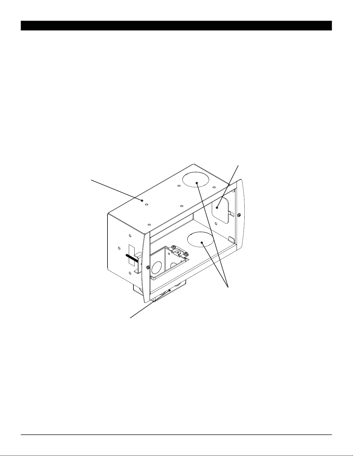
Spacious and Strong
Plenty of room to route cables and
cords, as well as store any excess
cord length to prevent strain.
Mounting Points
Allows you to choose from a
variety of mounting options.
GB-INWAVP
In-Wall Clamps
No need for a nearby wood stud!
Quick and easy mounting directly
to drywall.
Page 4
Power Box
Have your electrician install a
duplex receptacle so you can plug
in your at panel without the need
for unsightly cords running down
the wall to a nearby receptacle.
premiermounts.com | p. 800.368.9700 | e. [email protected]
Visit the Premier Mounts website at http://www.mounts.com Installation Instructions
Audio / Video Cable Knockouts
Allows you to route audio, video
and data connections through the
wall for a clean, concealed look.
Flexible
You can mount your in-wall box
horizontally, vertically, or even
upside-down to accommodate your
speci c power and audio/video
cabling needs.
Page 5
GB-INWAVP
Introduction
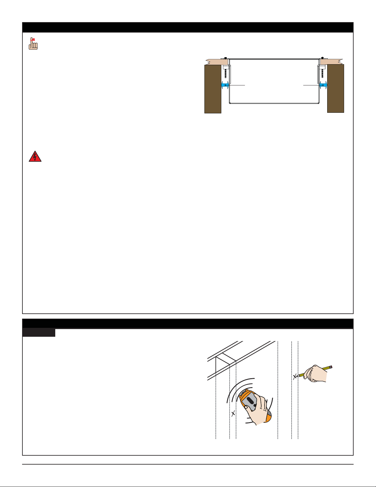
Your GB-INWAVP requires a minimum of ¾Ǝ
between the side of your GB-INWAVP and the
nearest wall stud for the In-Wall Clamps to properly
operate.
Prior to installing any hardware, Premier Mounts strongly
recommends that you carefully consider:
Where you intend to mount your at panel.
•
Where you intend to install your GB-INWAVP.
•
Whether you will be mounting your GB-INWAVP
•
horizontally, vertically, or inverted.
The proximity of nearby wood studs.
•
How electric power, audio, video, or data is going to be
•
routed to your GB-INWAVP.
Installation of your GB-INWAVP should be
performed by a quali ed professional. Improper
installation can result in property damage and
severe personal injury.
If you will be mounting your GB-INWAVP directly to
drywall, proceed to the “Drywall Installation” section.
Wood
Stud
¾Ǝ or Greater Distance
Plan View
Wood
Stud
If you will be mounting your GB-INWAVP to a wooden
stud, or if after cutting the hole in your drywall you
discover that you are too close to a wall stud, proceed to
the “Wood Stud Installation (Optional)” section.
Drywall Installation
Step 1
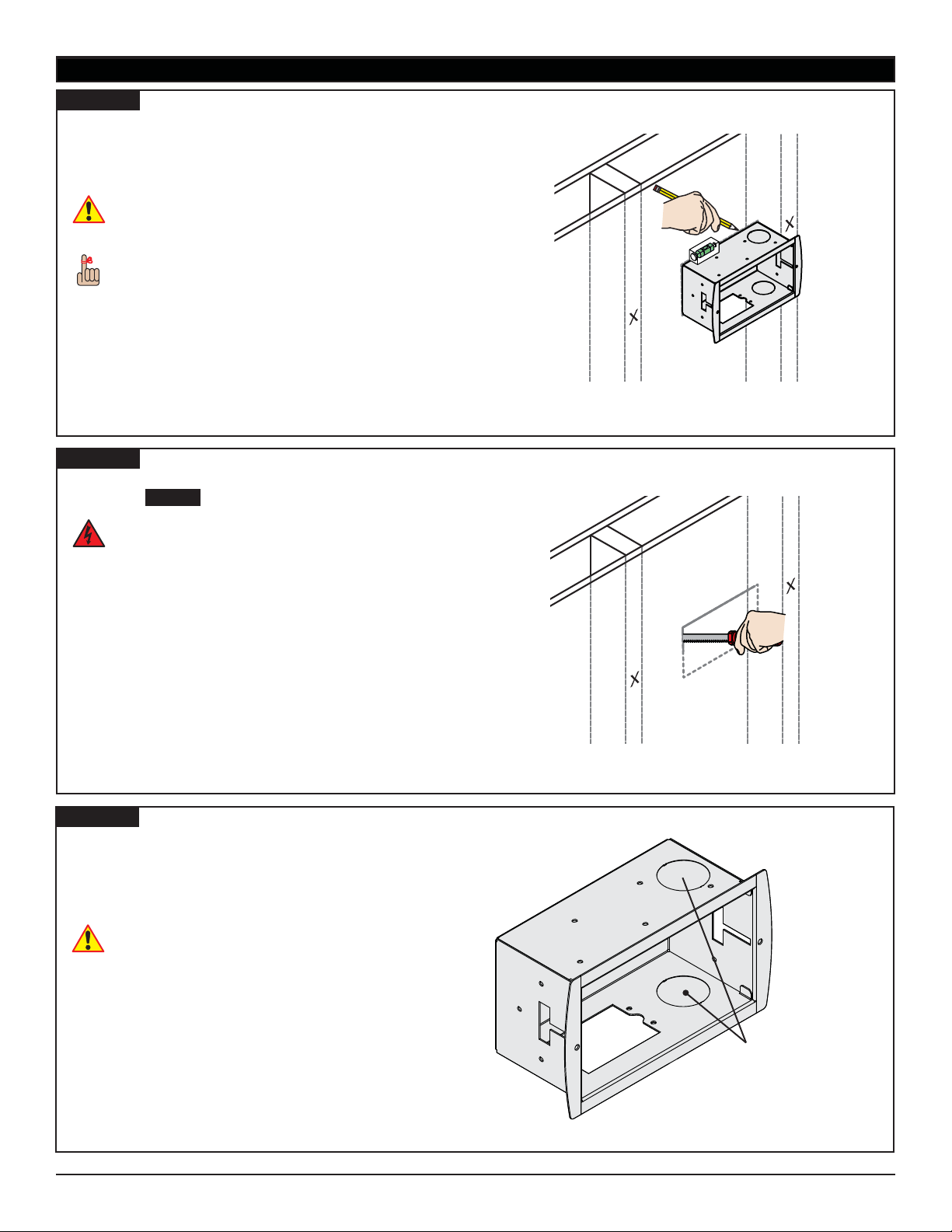
Use an electronic stud nder to locate all wall studs in
the area in which you intend to install your at panel
and your GB-INWAVP.
Use a pencil and lightly mark the location of each
®
stud.
If your at panel mounting bracket has suf ciently large
access openings, consider installing your GB-INWAVP
directly behind the at panel.
Installation Instructions
premiermounts.com | p. 800.368.9700 | e. [email protected]
Visit Premier Mounts website at http://www.mounts.com Page 5
Page 6
Drywall Installation (cont’d)
Step 2
Place your GB-INWAVP against wall.
Level your GB-INWAVP.
®
Use a pencil and draw an outline on the wall around
¯
your GB-INWAVP.
This is where you will be cutting a hole in the
drywall for your GB-INWAVP. Be absolutely certain
that this is where you want it installed.
Your GB-INWAVP requires a minimum of ½Ǝ
between the side of your GB-INWAVP and the
nearest wall stud for the In-Wall Clamps to properly
operate.
Step 3
Use a drywall saw to remove the drywall in the area you
marked in Step 2 .
GB-INWAVP
Avoid cutting electrical wires, water pipes, or gas
lines! Remove a small piece of drywall and use a
ashlight to look around for these hazards in the
area in which you will be cutting. Once you have
located any hazards, proceed to carefully remove
the rest of the drywall.
If you do locate any hazards, their presence may require
you to relocate either the hazard or your GB-INWAVP.
Consult a quali ed professional prior to relocating
electrical lines, gas lines, or water pipes.
Step 4
If you will be routing your audio, video, and/or data
connections through the wall, remove the 1½Ǝ knockout.
The 1½Ǝ knockout is easily removed by pressing hard
with your thumbs on either side of the knockout, then
twisting the knockout until it comes free.
Watch for sharp edges!
Page 6
premiermounts.com | p. 800.368.9700 | e. [email protected]
Visit the Premier Mounts website at http://www.mounts.com Installation Instructions
1½Ǝ Knockouts for
Audio / Video / Data
Connections
Page 7
GB-INWAVP
Drywall Installation (cont’d)
Step 5
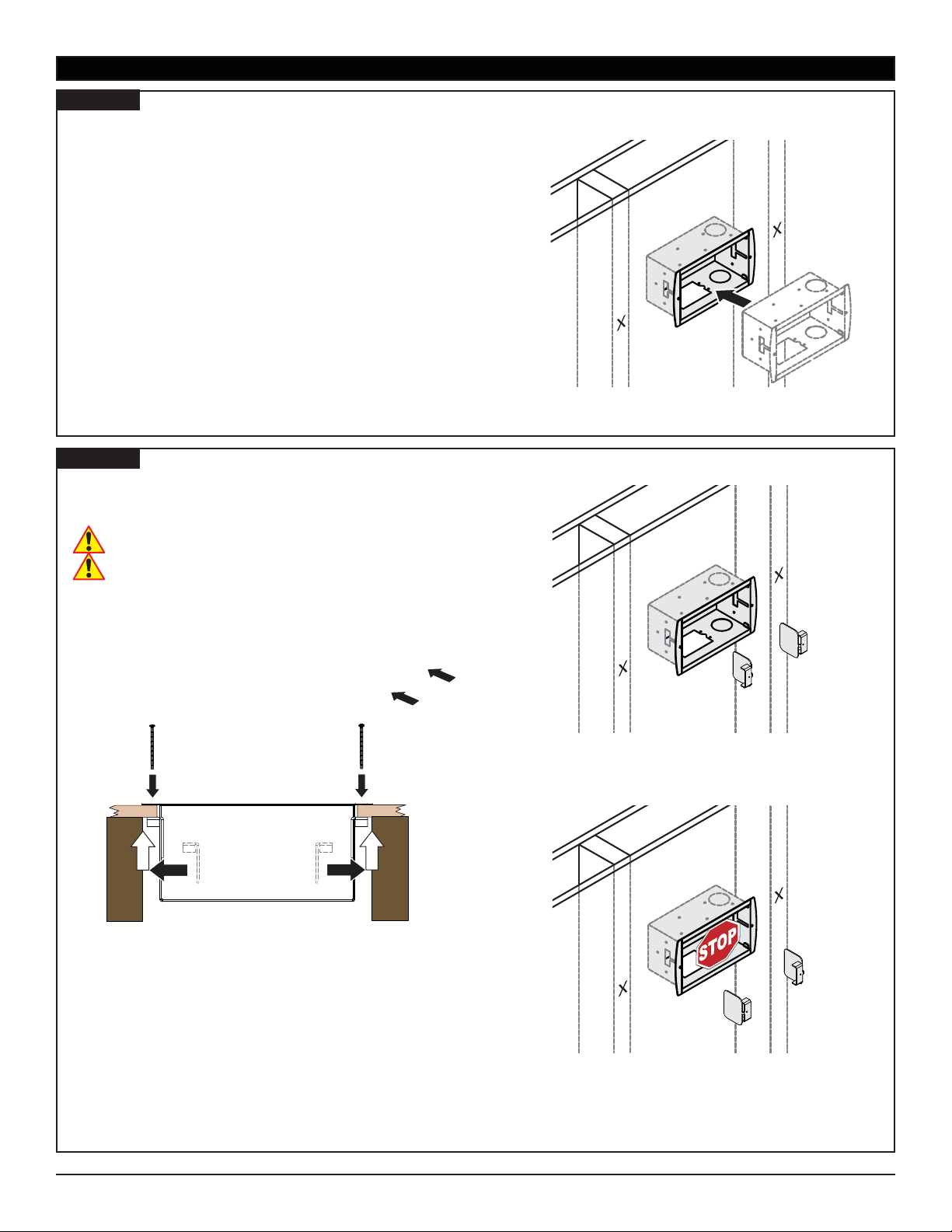
Insert your GB-INWAVP into the cutout.
Step 6
Insert one (1) In-Wall Clamp through the T-notch and
pull it forward. Fasten with one (1) 6-32 x 2Ǝ Panhead
Screw.
Do not overtighten the 6-32 x 2Ǝ Panhead Screw.
Note the proper orientation for the In-Wall Clamp.
Repeat for the remaining In-Wall Clamp.
Proceed to the “Outlet Box Installation” section.
6-32 x 2
Ǝ Panhead Screws
In-Wall Clamps
Plan View
Proper Orientation
Proper Orientation
Installation Instructions
Improper Orientation
premiermounts.com | p. 800.368.9700 | e. [email protected]
Visit Premier Mounts website at http://www.mounts.com Page 7
Page 8
Wood Stud Installation (Optional)
Step 1
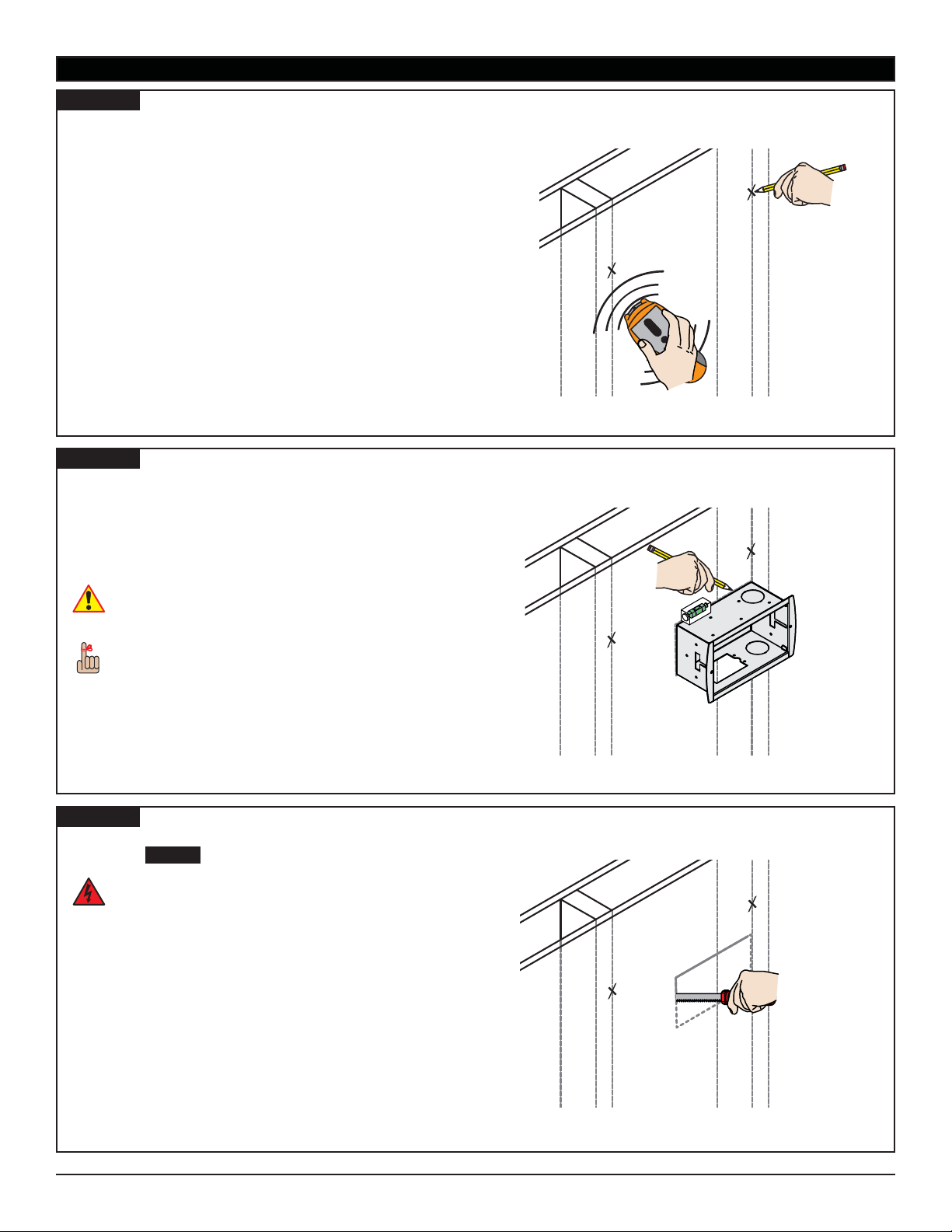
Use an electronic stud nder to locate all wall studs in
the area in which you intend to install your at panel
and your GB-INWAVP.
Use a pencil and lightly mark the location of each
®
stud.
If your at panel mounting bracket has suf ciently large
access openings, consider installing your GB-INWAVP
directly behind the at panel.
Step 2
Place your GB-INWAVP against the wall with one
edge of your GB-INWAVP aligned with the edge of a
stud.
Level your GB-INWAVP.
®
Use a pencil and draw an outline on the wall around
¯
your GB-INWAVP.
This is where you will be cutting a hole in the
drywall for your GB-INWAVP. Be absolutely certain
that this is where you want it installed.
GB-INWAVP
Your GB-INWAVP requires a minimum of ¾Ǝ
between the side of your GB-INWAVP and the
nearest wall stud for the In-Wall Clamps to properly
operate.
Step 3
Use a drywall saw to remove the drywall in the area you
marked in Step 2 .
Avoid cutting electrical wires, water pipes, or gas
lines! Remove a small piece of drywall and use a
ashlight to look around for these hazards in the
area in which you will be cutting. Once you have
located any hazards, proceed to carefully remove
the rest of the drywall.
If you do locate any hazards, their presence may require
you to relocate either the hazard or your GB-INWAVP.
Consult a quali ed professional prior to relocating
electrical lines, gas lines, or water pipes.
Page 8
premiermounts.com | p. 800.368.9700 | e. [email protected]
Visit the Premier Mounts website at http://www.mounts.com Installation Instructions
Page 9
GB-INWAVP
Wood Stud Installation (Optional) (cont’d)
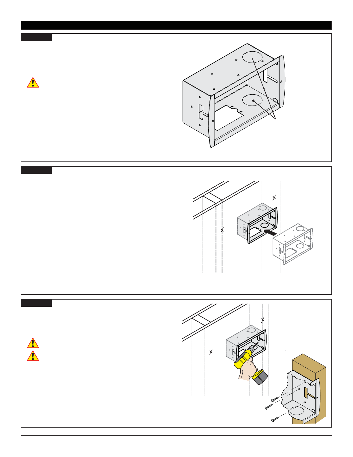
Step 4
If you will be routing your audio, video, and/or data
connections through the wall, remove the 1½Ǝ knockout.
The 1½Ǝ knockout is easily removed by pressing hard
with your thumbs on either side of the knockout, then
twisting the knockout until it comes free.
Watch for sharp edges!
Step 5
Insert your GB-INWAVP into the cutout.
1½Ǝ Knockouts for
Audio / Video / Data
Connections
Step 6
Drill a ¼Ǝ pilot hole in each of the three (3) mounting
points.
Insert one (1) commercially available wood screw into
each of the pilot holes and hand tighten.
Do not overtighten the wood screws.
Do not use a power drill to thread in the wood
screws.
Proceed to the “Outlet Box Installation” section.
premiermounts.com | p. 800.368.9700 | e. [email protected]
Installation Instructions
Visit Premier Mounts website at http://www.mounts.com Page 9
Page 10
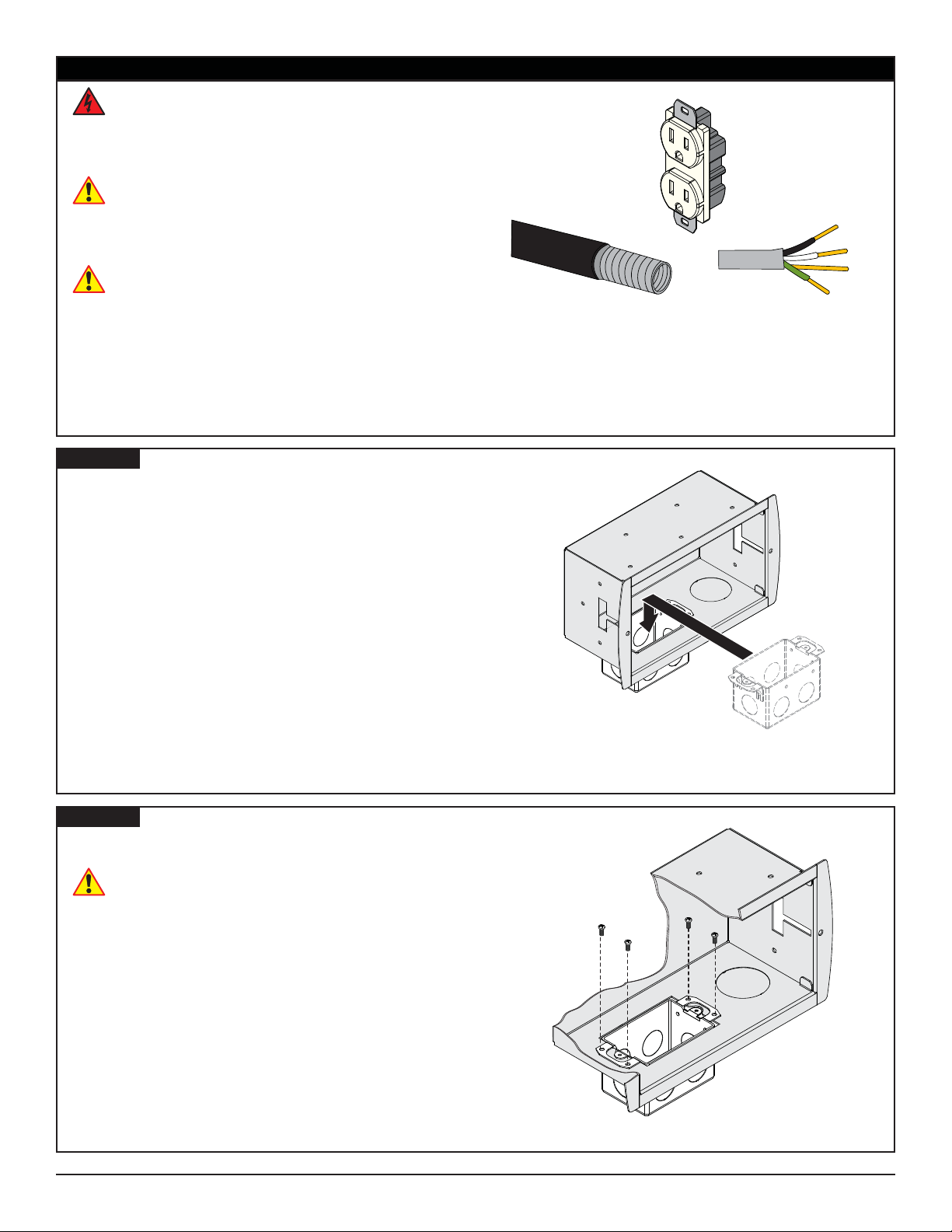
Outlet Box Installation
Installation of electrical power to your GB-INWAVP
should be performed by a quali ed professional
electrician. Improper installation and handling of
live electrical wires can result in property damage
and severe personal injury.
The 110 volt duplex receptacle, exible aluminum
conduit, and electrical wiring are not included with
your GB-INWAVP. You or your electrician can
purchase these at your local hardware store or
electrical supply shop.
The following steps presume that you have already
run exible aluminum conduit and electrical wiring
up to your GB-INWAVP.
Step 1
Remove one of the ½Ǝ knockouts from the back of the
Outlet Box.
Connect the exible aluminum conduit using
®
commercially available conduit connectors most
appropriate for your speci c installation.
Install a 110 volt duplex receptacle into the Outlet
¯
Box.
Place the Outlet Box into your GB-INWAVP.
°
GB-INWAVP
Not Included
Step 2
Secure the Outlet Box to your GB-INWAVP using four
(4) 6-32 x ½" screws.
Do not overtighten the 6-32 x ½” screws.
Proceed to the “Installing the Cable Bushings”
section.
Page 10
premiermounts.com | p. 800.368.9700 | e. [email protected]
Visit the Premier Mounts website at http://www.mounts.com Installation Instructions
Page 11
GB-INWAVP
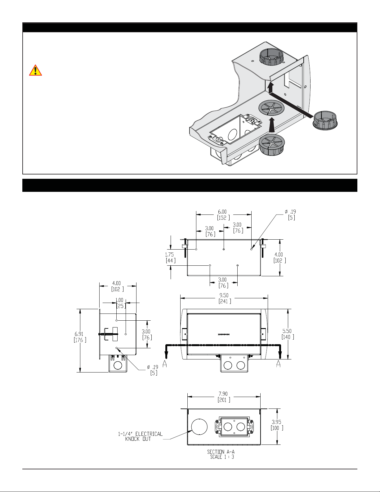
Installing the Cable Bushings
The knockouts for your audio / video / data cables should
already be removed. If you have not removed them
yet, press hard with your ngertips on either side of the
knockouts, then twist the knockout until they come free.
Watch for sharp edges!
Install the cable bushings gently pressing them into
the knockout holes.
Run your audio, video, and data cables through the
®
cable bushings.
Proceed with installing your at panel mount.
Technical Specifi cations
All measurements are in inches(mm).
Installation Instructions
premiermounts.com | p. 800.368.9700 | e. [email protected]
Visit Premier Mounts website at http://www.mounts.com Page 11
Page 12

GB-INWAVP
Warranty
Warranty
PREMIER MOUNTS
LIMITED LIFETIME WARRANTY
What and Who is Covered by this Limited Warranty and for How Long
Premier Mounts warrants this product to be free from defects in material and workmanship for the lifetime of the original
owner of this product. The limited warranty is valid only for the original purchaser of the product.
What Premier Mounts Will Do
At the sole option of Premier Mounts, Premier Mounts will repair or replace any product or product part that is defective.
If Premier Mounts chooses to replace a defective product or part, a replacement product or part will be shipped to you
at no charge, but you must pay any labor costs.
What is Not Covered; Limitations
PREMIER MOUNTS DISCLAIMS ANY LIABILITY FOR DAMAGE TO MOUNTS, ADAPTERS, DISPLAYS,
PROJECTORS, OTHER PROPERTY, OR PERSONAL INJURY RESULTING, IN WHOLE OR IN PART, FROM
IMPROPER INSTALLATION, MODIFICATION, USE OR MISUSE OF ITS PRODUCTS.
PREMIER MOUNTS DISCLAIMS ALL OTHER WARRANTIES, EXPRESS OR IMPLIED, INCLUDING WARRANTIES
OF MERCHANTABILITY AND FITNESS FOR A PARTICULAR PURPOSE. PREMIER MOUNTS IS NOT
RESPONSIBLE FOR INCIDENTAL OR CONSEQUENTIAL DAMAGES, INCLUDING BUT NOT LIMITED TO,
INABILITY TO USE ITS PRODUCTS OR LABOR COSTS FOR REMOVING AND REPLACING DEFECTIVE
PRODUCTS OR PARTS. SOME STATES DO NOT ALLOW THE EXCLUSION OR LIMITATION OF INCIDENTAL OR
CONSEQUENTIAL DAMAGES, SO THE ABOVE LIMITATION OR EXCLUSION MAY NOT APPLY TO YOU.
What Customers Must Do for Limited Warranty Service
If you discover a problem that you think may be covered by the warranty you MUST REPORT it in writing to the address
below within thirty (30) days. Proof of purchase (an original sales receipt) from the original consumer purchaser must
accompany all warranty claims. Warranty claims must also include a description of the problem, the purchaser’s name,
address, and telephone number. General inquiries can be addressed to Premier Mounts Customer Service at 1-800368-9700. Warranty claims will not be accepted over the phone or by fax.
PREMIER MOUNTS
ATTN: Warrenty Claims
500 W Central Ave, Suite A
Brea, CA 92821
How State Law Applies
THIS WARRANTY GIVES YOU SPECIFIC LEGAL RIGHTS, AND YOU MAY ALSO HAVE OTHER RIGHTS WHICH
VARY FROM STATE TO STATE.
Disclaimer
Premier Mounts intends to make this manual accurate and complete. However, Premier Mounts makes no claim that
the information contained herein covers all details, conditions or variations, nor does it provide for every possible
contingency in connection with the installation or use of this product. The information contained in this document
is subject to change without notice or obligation of any kind. Premier Mounts makes no representation of warranty,
expressed or implied, regarding the information contained herein. Premier Mounts assumes no responsibility for
accuracy, completeness or suf ciency of the information contained in this document.
PREMIER MOUNTS
©
500 W Central Ave, Suite A
Brea, CA 92821
USA & CANADA
Phone: 800-368-9700
Fax: 800-832-4888
Page 12
premiermounts.com | p. 800.368.9700 | e. [email protected]
Visit the Premier Mounts website at http://www.mounts.com Installation Instructions
 Loading...