

Page 1
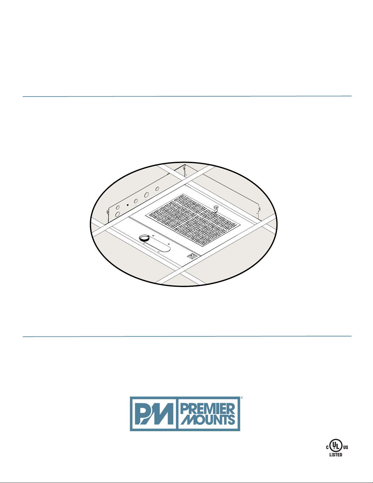
GB-AVSTOR5
Ceiling Equipment Storage Box with Pipe Coupler
INSTALLATION INSTRUCTIONS
premiermounts.com | p. 800.368.9700 | e. [email protected]
500 W Central Ave, Suite A, Brea, CA 92821 USA
Page 2
GB-AVSTOR5
Contents
Weight Limit. .................................................................................................................................................................... 2
Total Voltage Limit ........................................................................................................................................................... 2
Warning Statements. ....................................................................................................................................................... 2
Installation Tools. ............................................................................................................................................................. 3
Parts List.......................................................................................................................................................................... 4
Features. ......................................................................................................................................................................... 4
GB-AVSTOR5 Installation. .............................................................................................................................................. 5
Introduction. .............................................................................................................................................................. 5
Lid Removal.............................................................................................................................................................. 5
Ceiling Box Installation. ................................................................................................................................................... 6
Wiring the Electrical Box................................................................................................................................................ 10
Removing the Electrical Knockouts (optional). ....................................................................................................... 10
Mounting Tray Installation...............................................................................................................................................11
Ceiling NPT Adapter Plate Adjustment. ......................................................................................................................... 12
Securing the 1 ½˝ NPT Pipe to the GB-AVSTOR5. ....................................................................................................... 12
Securing the Lid............................................................................................................................................................. 13
Technical ............................................................................................................................................... 14
Warranty. ....................................................................................................................................................................... 15
Weight Limit
Total Maximum Weight:
(includes NPT pipe, projector,
& hardware being mounted)
50 lbs.
THE CEILING STRUCTURE MUST BE CAPABLE OF
SUPPORTING AT LEAST FOUR TIMES THE WEIGHT OF
THE CEILING BOX. IF NOT, THE CEILING STRUCTURE
MUST BE REINFORCED.
Total Voltage Limit
The maximum voltage of this product is 120vac.
The maximum combined total amps for all outlets are not to exceed 12 AMPS or equivalent.
Warning Statements
PRIOR TO THE INSTALLATION OF THIS PRODUCT, THE INSTALLATION INSTRUCTIONS MUST BE READ AND
COMPLETELY UNDERSTOOD. KEEP THESE INSTALLATION INSTRUCTIONS IN AN EASILY ACCESSIBLE LOCATION
FOR FUTURE REFERENCE.
PROPER INSTALLATION PROCEDURE BY A QUALIFIED SERVICE TECHNICIAN MUST BE FOLLOWED, AS OUTLINED
IN THESE INSTALLATION INSTRUCTIONS. FAILURE TO DO SO COULD RESULT IN PROPERTY DAMAGE, SERIOUS
PERSONAL INJURY, OR EVEN DEATH.
SAFETY MEASURES MUST BE PRACTICED AT ALL TIMES DURING THE ASSEMBLY OF THIS PRODUCT. USE
PROPER SAFETY EQUIPMENT AND TOOLS FOR THE ASSEMBLY PROCEDURE TO PREVENT PERSONAL INJURY.
PREMIER MOUNTS DOES NOT WARRANT AGAINST DAMAGE CAUSED BY THE USE OF ANY PREMIER MOUNTS
PRODUCT FOR PURPOSES OTHER THAN THOSE FOR WHICH IT WAS DESIGNED OR DAMAGE CAUSED BY
UNAUTHORIZED ATTACHMENTS OR MODIFICATIONS, AND IS NOT RESPONSIBLE FOR ANY DAMAGES, CLAIMS,
DEMANDS, SUITS, ACTIONS OR CAUSES OF ACTION OF WHATEVER KIND RESULTING FROM, ARISING OUT OF OR
IN ANY MANNER RELATING TO ANY SUCH USE, ATTACHMENTS OR MODIFICATIONS.
At least two people should perform the assembly procedure. Personal injury and/or property damage can result
from dropping or mishandling the projector.
This product is intended for indoor use only. Use of this product outdoors could lead to product failure and/or serious
personal injury.
Do not install near sources of high heat. Do not install on a structure that is prone to vibration, movement or chance of
impact.
Page 2 Installation Instructions
premiermounts.com | p. 800.368.9700 | e. [email protected]
Page 3
GB-AVSTOR5
AVERTISSEMENT
AVANT L’INSTALLATION DE CE PRODUIT, LES CONSIGNES D’INSTALLATION DOIVENT ÊTRE LUES ET PLEINEMENT
COMPRISES. CONSERVER CES CONSIGNES D’INSTALLATION DANS UN ENDROIT FACILEMENT ACCESSIBLE
POUR RÉFÉRENCE FUTURE.
LA PROCÉDURE D’INSTALLATION CORRECTE PAR UN TECHNICIEN QUALIFIÉ DOIT ÊTRE OBSERVÉE, COMME
DÉCRIT DANS CES CONSIGNES D’INSTALLATION. FAUTE DE QUOI DES DOMMAGES MATÉRIELS, BLESSURES
GRAVES, VOIRE MÊME LA MORT PEUT SUBVENIR.
DES MESURES DE SÉCURITÉ DOIVENT ÊTRE PRATIQUÉES À TOUT MOMENT DURANT L’ASSEMBLAGE DE CE
PRODUIT. UTILISER L’ÉQUIPEMENT ET OUTILS DE SÉCURITÉ APPROPRIÉ POUR LA PROCÉDURE D’ASSEMBLAGE
AFIN D’ÉVITER DES BLESSURES.
LES SUPPORTS PREMIER MOUNTS NE GARANTISSENT PAS CONTRE LES DOMMAGES CAUSÉS PAR L’USAGE DU
PRODUIT DE MONTAGE PREMIER MOUNTS À D’AUTRES FINS QUE CELLES POUR LESQUELLES IL A ÉTÉ CONÇU
OU DES DOMMAGES CAUSÉS PAR DES ACCESSOIRES OU DES MODIFICATIONS NON AUTORISÉS, ET NOUS
NE POUVONS PAS ÊTRE TENUS RESPONSABLES DES DOMMAGES, PLAINTES, RÉCLAMATIONS, POURSUITES,
ACTIONS OU CAUSES D’ACTION DE N’IMPORTE QUELLE MANIÈRE RÉSULTANT DE, DÉCOULANT DE OU
TOUCHANT DE N’IMPORTE QUELLE MANIÈRE UN TEL USAGE, ACCESSOIRE OU MODIFICATION
At least two people should perform the assembly procedure. Personal injury and/or property damage can result
from dropping or mishandling the projector.
Ce produit n’est destiné qu’à être utilisé à l’intérieur. L’utilisation de ce produit à l’extérieur pourrait entraîner des défauts
matériels et/ou des blessures graves.
Ne pas installer près de sources de forte chaleur. Ne pas installer sur une structure soumise aux vibrations, aux
mouvements ou aux chocs.
Installation Tools
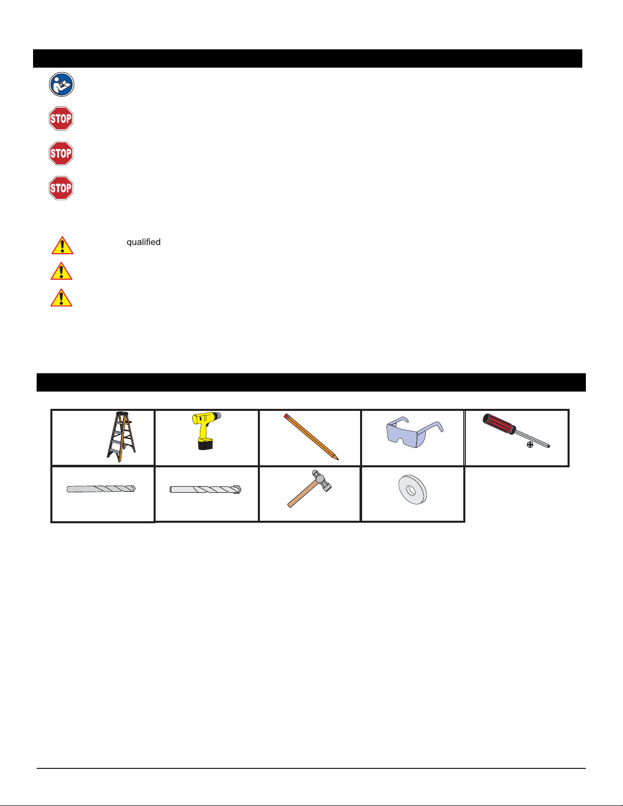
The following tools may be required depending upon your particular installation. They are not included.
Ladder
Phillips Tip ScrewdriverHand Held Drill
1/8˝ Drill Bit 1/4” Concrete Drill Bit
Pencil Protective Eyewear
Hammer
Flat Washers
Installation Instructions Page 3
premiermounts.com | p. 800.368.9700 | e. [email protected]
Page 4
GB-AVSTOR5
Parts List
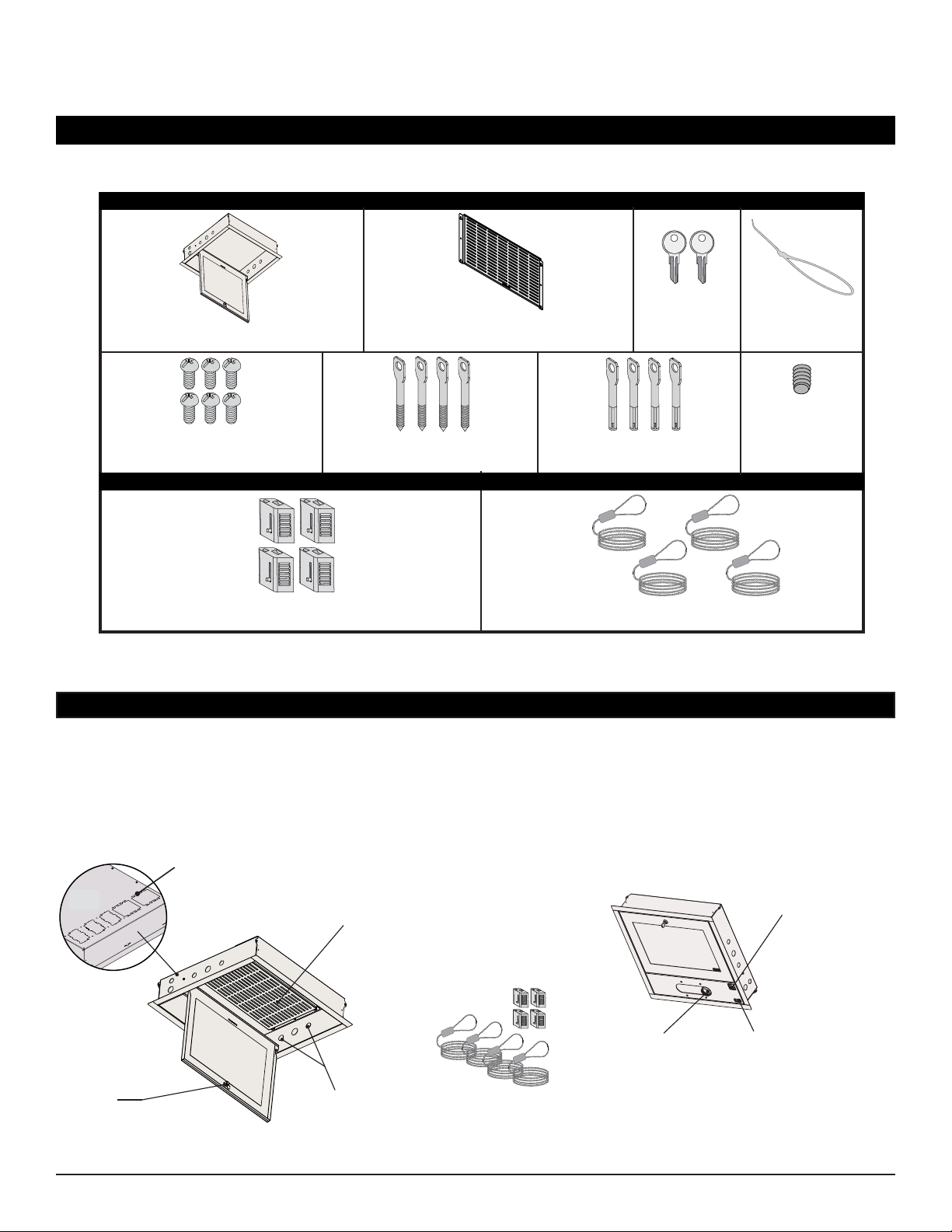
Make sure your Premier Mounts product has the following hardware and components before beginning installation.
GB-AVSTOR5 Hardware
GB-AVSTOR5 Ceiling Box (Qty 1)
M5 x 8mm Phillips Head Screws
(Qty 6)
Equipment Mounting Tray (Qty 1)
1/4” x 3” Eye Lag Screws
(Qty 4)
M6 x 2.4” Eye Anchor Bolts
Keys (Qty 2)
(Qty 4)
Zip Ties (Qty 12)
M5 x 6mm Set
Screw (Qty 1)
Quick Lock Cable Kit
Quick Locks
(Qty 4)
1
/16˝ Braided Cable
(Qty 4 Strands)
Features
The GB-AVSTOR5 Ceiling Equipment Storage GearBox™ with integrated pipe coupler provides a secure and discrete
storage-and-mounting solution for false ceiling projector installations. Integrated power receptacles, a removable
equipment mounting tray and an adjustable mounting platform for 1½” NPT pipe make the GB-AVSTOR5 an
indispensible, centralized A/V installation accessory.
Top View
Security
Lockable access panel keeps
A/V gear safe
Page 4 Installation Instructions
Top Knockouts
Multiple, single and dual-gang knockouts for
signal and power (knockout covers not shown)
Removable Equipment Tray
Tray allows A/V components
to be pre-wired prior to the
installation
Side Knockouts
Multiple 1” and 3/4” knockouts
provide low voltage electrical
conduit connector access
Tile Replacement
Replaces standard 2’ x 2’
ceiling tile
Includes the Quick Lock Cable Kit
premiermounts.com | p. 800.368.9700 | e. [email protected]
Mounting Coupler
1 ½” NPT pipe coupler
provides 6” of lateral shift
Power Receptacle
Conveniently connect the
projector or another device to
the integrated electrical outlet
Power Toggle
Easily turn on or off
the power receptacle
Page 5
GB-AVSTOR5
GB-AVSTOR5 Installation
Introduction
Please read these installation instructions thoroughly before installing your Premier Mounts product.
Please take a minute to familiarize yourself with the contents of the package and make sure you have all the parts and
tools you need to safely complete the installation.
In addition, some steps of this installation may require two people to prevent personal injury and/or damage to your
equipment. Please observe all warnings in the following installation procedure and utilize proper safety equipment at
all times.
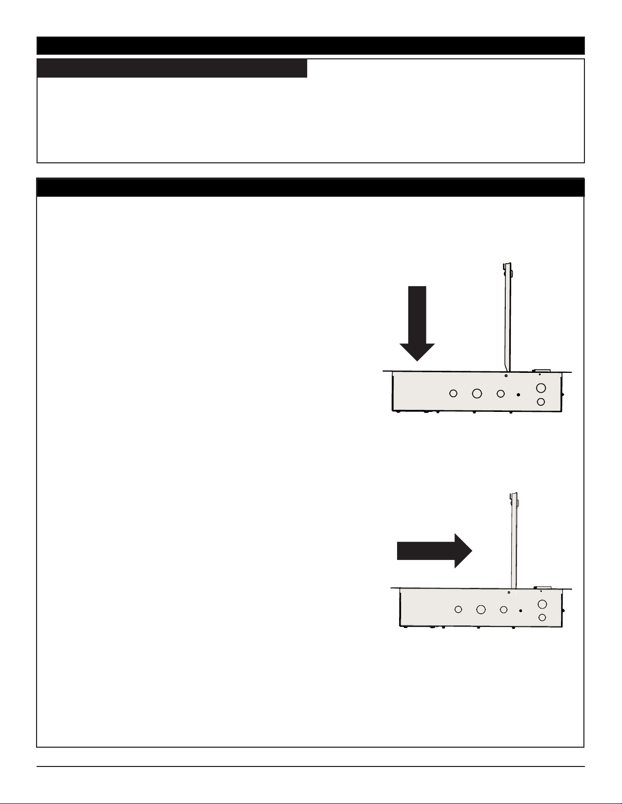
Lid Removal
1) Unlock and open the lid.
2) Push the lid in and away from the metal hinges
(Figure 1).
3) Push the lid in the direction of the mounting coupler
(Figure 2).
4) Once the lid hinge is unattached, pull the lid carefully
out from the ceiling box.
Go to Ceiling Box Installation on page 6.
Figure 1
Figure 2
Ceiling Box Side View
Installation Instructions Page 5
premiermounts.com | p. 800.368.9700 | e. [email protected]
Page 6
Ceiling Box Installation
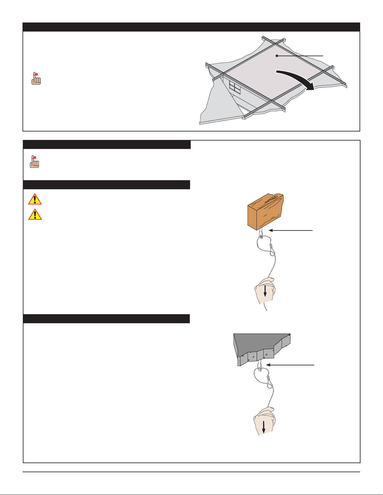
1) Determine the desired location where the
GB-AVSTOR5 is to be located.
2) Remove the ceiling tile where the ceiling box will be
mounted.
Store the ceiling tile in a safe location in the event
that it needs to be reused.
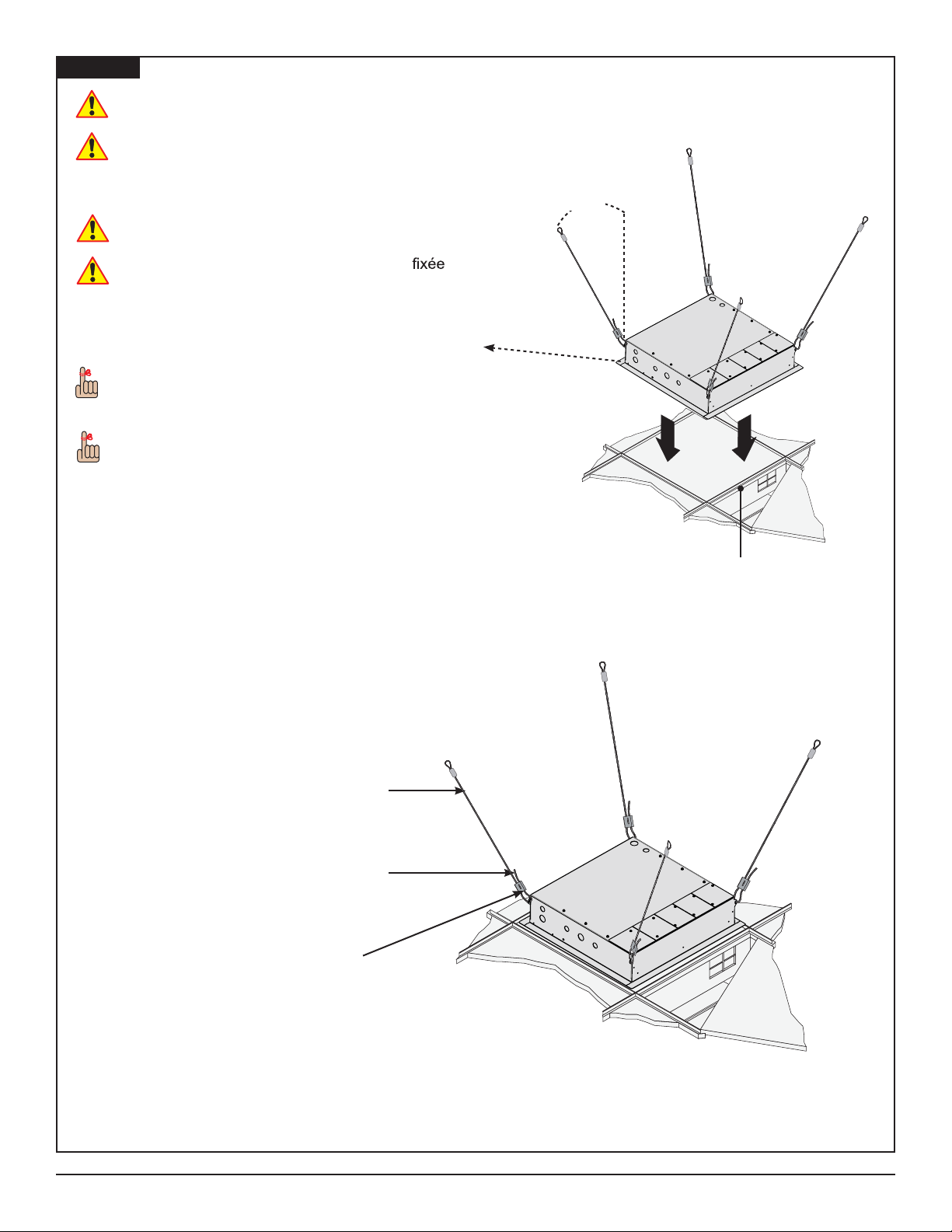
Ceiling Attachment
The ceiling box must be secured using the Quick
Locks and 1/16” braided cables (supplied).
GB-AVSTOR5
Ceiling Tile
Wood Stud Ceiling
Minimum of 2 by 4 wood stud to be used
Minimum de 2 par 4 bois goujon pour être utilisé
1) Determine the mounting location.
2) Use a 1/8” drill bit to pre-drill the mounting holes.
3) Secure the four (4) 1/4” eye lag screws to the wood
stud in the ceiling.
4) Run the open end of the 1/16” braided cable through
the hole in an eye lag screw.
5) Run the open end through the loop.
6) Pull the open end down until the 1/16” braided cable
tightens around the eye lag screw.
7) Repeat steps 4-6 for the remaining three mounting
points.
Concrete Ceiling
1) Determine the mounting location.
2) Use a 1/4” concrete drill bit to drill the mounting holes.
3) Place the concrete eye anchor bolts into the predrilled holes and gently tap into place using a rubber
mallet or hammer.
4) Run the open end 1/16” braided cable through the
hole in an eye anchor bolt.
5) Run the open end through the loop.
6) Pull the open end down until the braided cable
tightens around the eye anchor bolt.
7) Repeat steps 4-6 for the remaining three mounting
points.
Wood Stud
Eye Lag Screw
Solid Surface
Eye Anchor Bolt
Page 6 Installation Instructions
premiermounts.com | p. 800.368.9700 | e. [email protected]
Page 7
GB-AVSTOR5
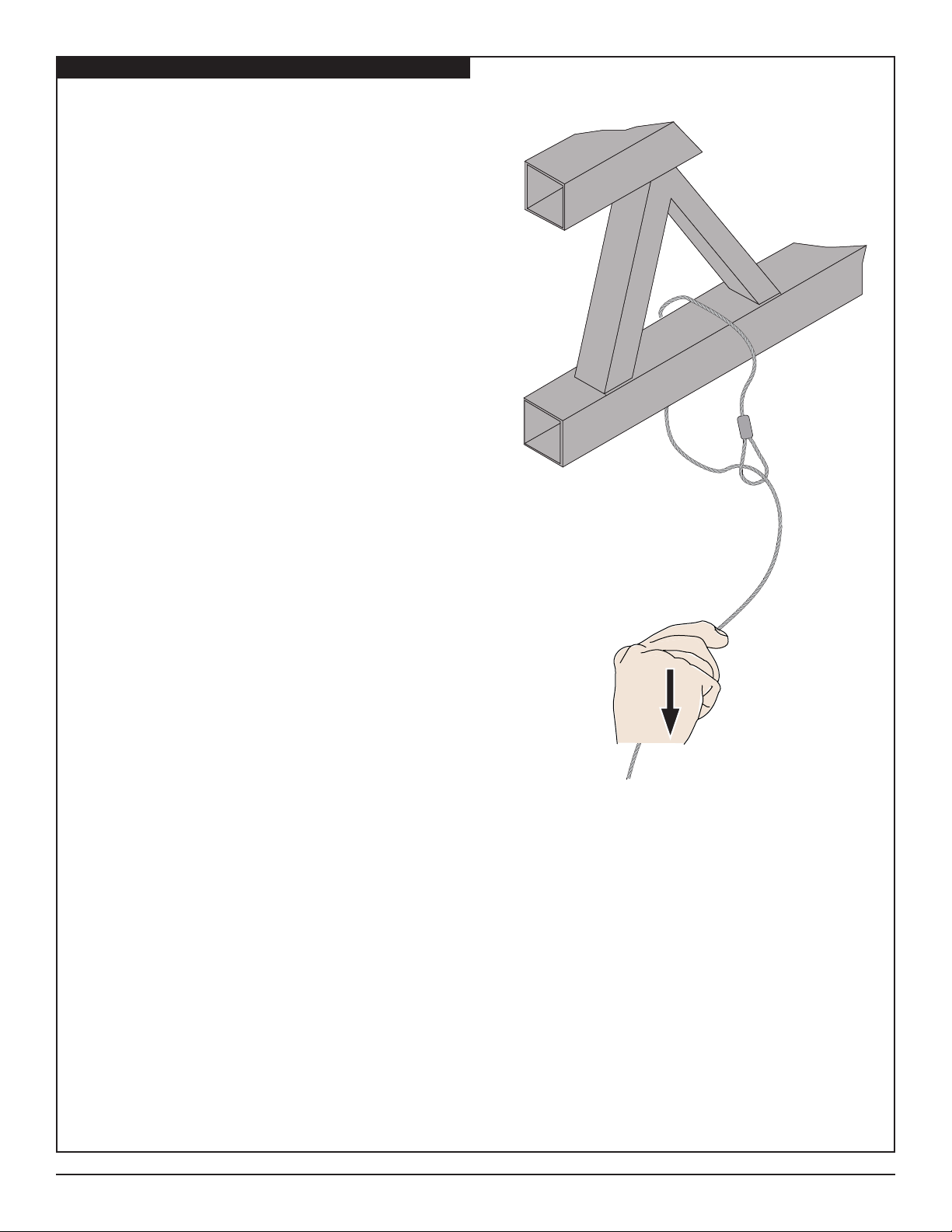
Truss Ceiling
1) Loop the braided cable around the truss.
2) Run the open end 1/16” braided cable through the
loop.
3) Pull the open end down until the 1/16” braided cable
tightens around the truss.
4) Repeat steps 1-3 for the remaining three mounting
points.
Go to Quick Lock Operation on page 8.
Ceiling Truss
Installation Instructions Page 7
premiermounts.com | p. 800.368.9700 | e. [email protected]
Page 8
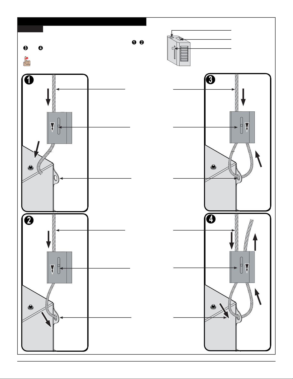
Quick Lock Operation
Step 1
GB-AVSTOR5
Cable Output
Please follow the steps below in numerical order , ,
and to correctly install the Quick Lock Cable Kit.
To release or relieve tension on the 1/16” braided
cable, slide the release pin to disengage.
1/16” Braided Cable
Release Pin
Cable Input
Release Pin
Mounting Hole
1/16” Braided Cable
Release Pin
Mounting Hole
Page 8 Installation Instructions
premiermounts.com | p. 800.368.9700 | e. [email protected]
Page 9
W
Step 2
It is recommended that the following steps be
performed by two people.
l est recommandé que les étapes suivantes soient
exécutées par deux personnes.
1) Lower the ceiling box into the exposed ceiling
framework.
Make sure the ceiling box is seated completely in
the ceiling framework before releasing it.
S’assurer que La boîte de plafond est bien
dans la charpente du plafond avant de la relâcher.
2) Adjust the 1/16” braided cable so that the cable
forms a
15° angle away from the corner of the ceiling box.
When adjusting the tension of the weight-bearing
side of the Quick Lock, the 1/16”
braided cable must
be pulled through the Quick Lock until the desired
tension is attained. Do not overtighten.
15°
3) When you have the desired tension, pull the 1/16”
braided cable through the other side of the Quick
Lock.
Once the tension has been adjusted, be sure that there
is a minimum of 6” of excess 1/16” braided cable on the
non-weight bearing side of the Quick Lock.
4) Use cable cutters to remove any remaining 1/16”
braided cable (optional).
Go to Wiring the Electrical Box on page 10.
1/16” Braided
Cable To Ceiling
Attachment
6” Excess
1/16” Braided Cable
Quick Lock
Ceiling
Framework
Installation Instructions Page 9
premiermounts.com | p. 800.368.9700 | e. [email protected]
Page 10
Wiring Requirements
WARNING!
The grounding conductor is to be grounded to earth at the service equipment, or if supplied by a separately derived system, at the supply transformer or motor-generator set.
Verify that all branch circuit (mains) and low-voltage (control) circuits are de-energized, and locked out before installing cables or making connections
Ensure that you are making connections to an on/off breaker panel.
Wiring by a
Check national and local codes before wiring. Select wire size and connectors according to these codes.
Ensure that the total load being plugged into panel DOES NOT EXCEED the circuit breaker rating
Le conducteur de masse doit être mis à la terre au niveau de l’équipement de service, ou s’il est fourni par un système séparément dérivé, au niveau du
transformateur d’énergie ou du groupe générateur de moteur.
que tout le circuit de dérivation (réseau d’alimentation) et les circuits basse tension (commande) sont désactivés, et bloqués avant de procéder à l’installation
des câbles ou aux différents raccordements
S’assurer que les raccordements se font sur un panneau de sectionnement de marche/arrêt.
Il est obligatoire que l’installation électrique soit exécutée par un électricien
les codes nationaux et locaux avant d’installer la canalisation électrique. Sélectionner les dimensions de et de connecteurs en fonction de ces codes.
S’assurer que la charge totale branchée dans le panneau N’EXCÈDE PAS le calibre du circuit du disjoncteur
electrician is required.
Wiring the Electrical Box
WARNING!
Do not install or modify electrical wiring unless you have read and follow
the requirements noted above.
ATTENTION !
Éviter d’installer ou de
les exigences susmentionnées.
The smaller knockouts along the sides of the box are to be used for low level
signal/low voltage routing. These are NOT for routing main power or signal.
Les plus petites alvéoles le long de la boîte sont destinées à l’acheminement du
signal de bas niveau/basse tension. Ces derniers NE doivent PAS être utilisés
pour l’acheminement de l’alimentation principale ou du signal.
l’installation électrique à mois d’avoir lu et suivi
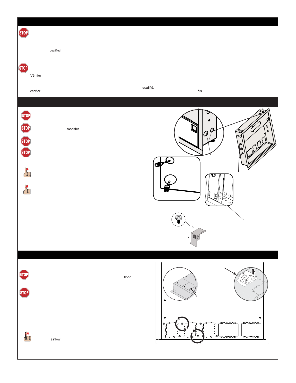
Mains Power
Knockouts
GB-AVSTOR5
Identify connection to branch circuit (mains supply) to attain proper
grounding/bonding.
Use wire nuts to match and secure wires accordingly.
Green denotes the grounding wire, the white and black are for power (Figure A).
Make sure all power is disconnected before making connections.
Remove two (2) M4 x 8mm Phillips combo screws to detach the electrical box from
the ceiling box
(Figure 2).
Punch out the appropriate power knockout(s) on the
•
side of the ceiling box (Figure 1).
Hook up all loose wiring in the electrical box.
•
Re-install the electrical box inside the ceiling box.
•
Removing the Electrical Knockouts (optional)
\
WARNING!
The 1-and 2-gang electrical knockouts on the back of the box are main
power. Only install the electrical box facing down, towards the
from the upper ceiling structure (Figure 3).
ATTENTION!
Les alvéoles électriques à 1-et 2-broches à l’arrière de la boîte sont rattachées
à l’alimentation principale. Installer simplement la boîte électrique face à terre,
tournée vers le pavement et écartée de la charpente du plafond supérieure
(Figure 3).
1) Remove screws from around the desired electrical knockouts (Figure 1) to
detach their covers.
2) Remove the knockout covers from the top of the
GB-AVSTOR5 (Figure 2).
If you no longer want to use a knockout, re-attach its cover to prevent
excessive
into the ceiling.
& away
M4 x 8mm Phillips
(Figure A)
combo screw
Figure 2
Figure 2
Low Level Signal/
Low Voltage Power
Knockouts
Figure 1
Grounding Wire
attached to
Grounding Lug
Electrical box inside the ceiling box shown
Electrical Box
Cut-out
Figure 3
Detach the knockout
cover
Go to Mounting Tray Installation on page 11.
Page 10 Installation Instructions
premiermounts.com | p. 800.368.9700 | e. [email protected]
Figure 1
1- and 2-gang electrical knockouts inside the
GB-AVSTOR5
Page 11
GB-AVSTOR5
Mounting Tray Installation
For ease of installation, the mounting tray comes packaged in a separate box within the master carton.
Installers may pre-wire the mounting tray prior to the GB-AVSTOR5 ceiling box installation. Zip ties are
included for your convenience. Please contact Premier Mounts for additional zip ties if needed.
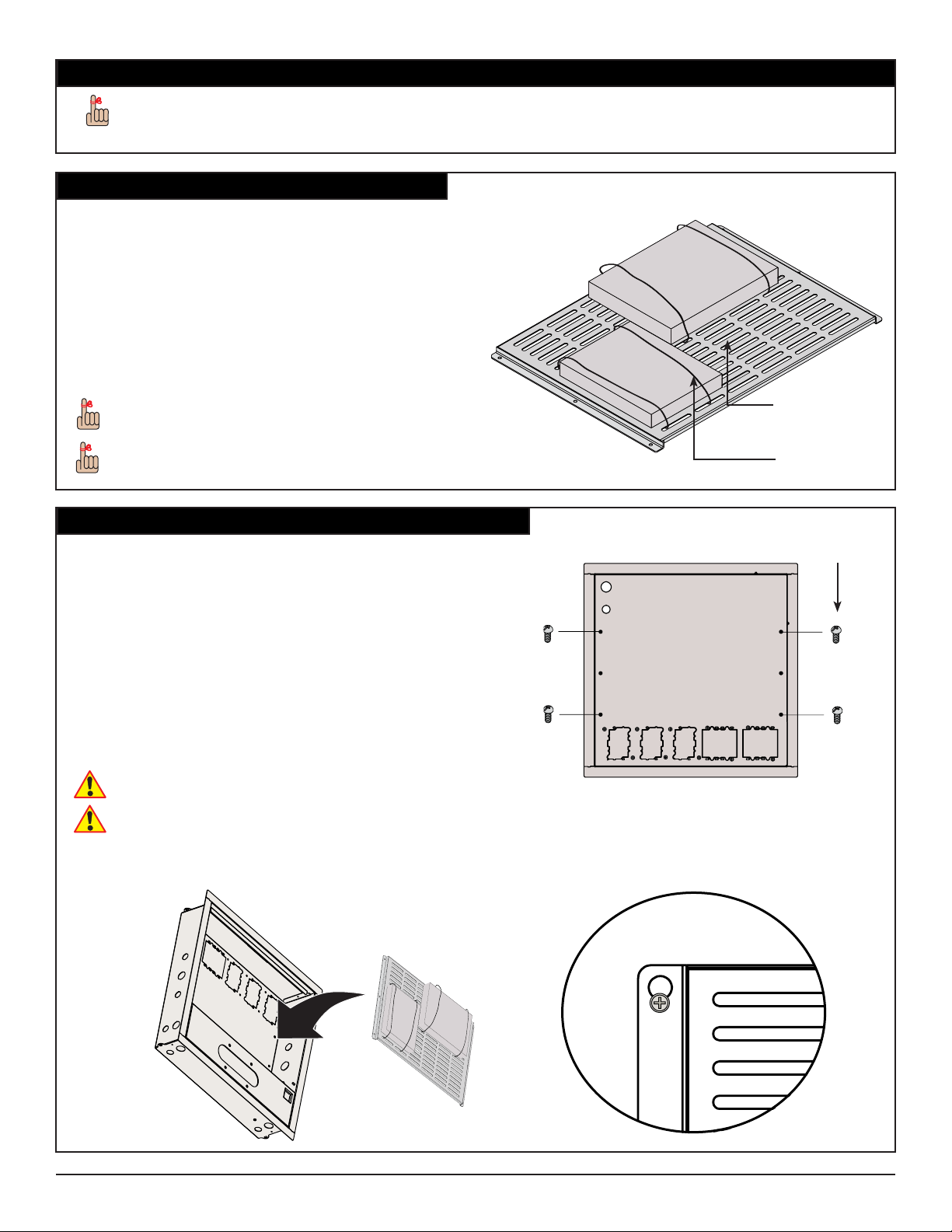
Attaching Equipment to the Tray
1) Place your electronic components onto the mounting
tray. The max weight that can be installed on
mounting tray is 10lb.
2) Align the electronic components so that the weight is
distributed as evenly as possible.
3) Run the zip ties through the mounting slots on the
tray, underneath the mounting tray and up through
the mounting slot on the other side of the electronic
component.
4) Tighten the zip tie down and cut off any excess zip
tie.
As a reminder, when installing equipment, secure
with a minumum of 2 zip ties, one per side. If very
large, please use a total of 4 zip ties, 2 per side.
As a reminder, when installing equipent to the
mounting tray, adhere to the proper installation of
all components to ensure proper ventilation.
Mounting Tray
Zip Tie
Attaching the Mounting Tray to the GB-AVSTOR5
1) Insert four (4) M5 x 8mm Phillips head screws loosely
into the outer holes inside the GB-AVSTOR5 (Figure
1).
2) Place the mounting tray into the middle section of the
GB-AVSTOR5 (Figure 2).
3) Hook the mounting tray onto the heads of the M5
x 8mm Phillips head screws on the GB-AVSTOR5
(Figure 3).
4) Insert two (2) M5 x 8mm Phillips head screws into the
middle mounting holes of the mounting tray.
5) Use a Phillips tip screwdriver to tighten all six (6)
screws.
Do not overtighten the mounting screws.
Éviter de trop serrer les vis de montage.
Continue to Ceiling NPT Adapter Plate Adjustment on
page 12.
M5 x 8mm Phillips
head screw
Inside view of GB-AVSTOR5
Figure 1
Figure 2 Figure 3
Installation Instructions Page 11
premiermounts.com | p. 800.368.9700 | e. [email protected]
Page 12
Ceiling NPT Adapter Plate Adjustment
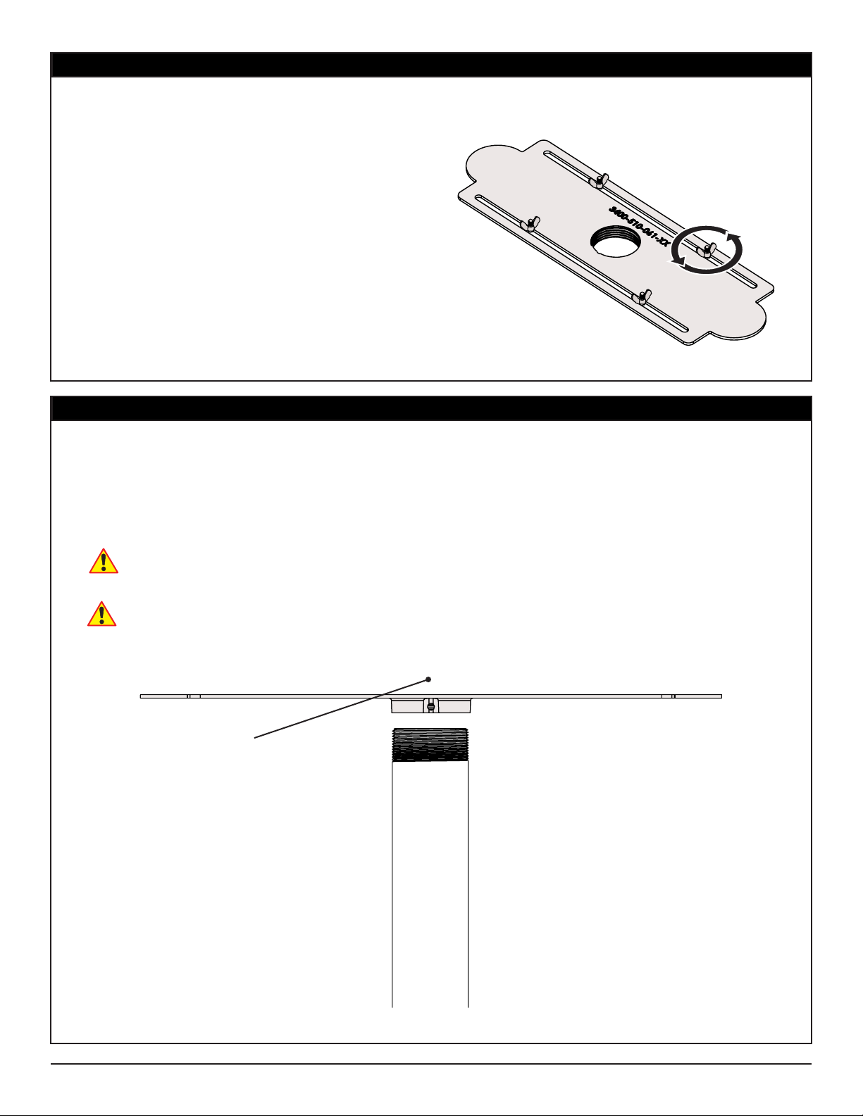
1) Locate the pre-installed ceiling NPT adapter plate
inside the GB-AVSTOR5.
2) Loosen the wingnuts.
3) Slide the ceiling NPT adapter plate to the desired
position.
4) Re-tighten the wingnuts.
Continue to Securing the 1 1/2” NPT Pipe to the GB-
AVSTOR5 below.
Securing the 1 1/2” NPT Pipe to the GB-AVSTOR5
1) Secure the 1 1/2” NPT pipe to the mounting coupler
and tighten the pipe.
2) The NPT pipe must complete a minimum of three (3)
full rotations in order to ensure that it is secured .
Use one (1) M5 x 6mm set screw to secure the pipe
to the plate.
GB-AVSTOR5
View of the ceiling NPT
adapter plate inside the
GB-AVSTOR5
The M5 x 6mm set screw must be used to
stabilize the 1 1/2” NPT pipe.
La vis de réglage M5 x 6 mm doit être utilisée
pour stabiliser le tuyau NPT de 1 1/2”.
Go to Securing the Lid on page 13.
M5 x 6mm set screw
Side view of the ceiling NPT
adapter plate inside the
GB-AVSTOR5
1 1/2” NPT pipe
Page 12 Installation Instructions
premiermounts.com | p. 800.368.9700 | e. [email protected]
Page 13
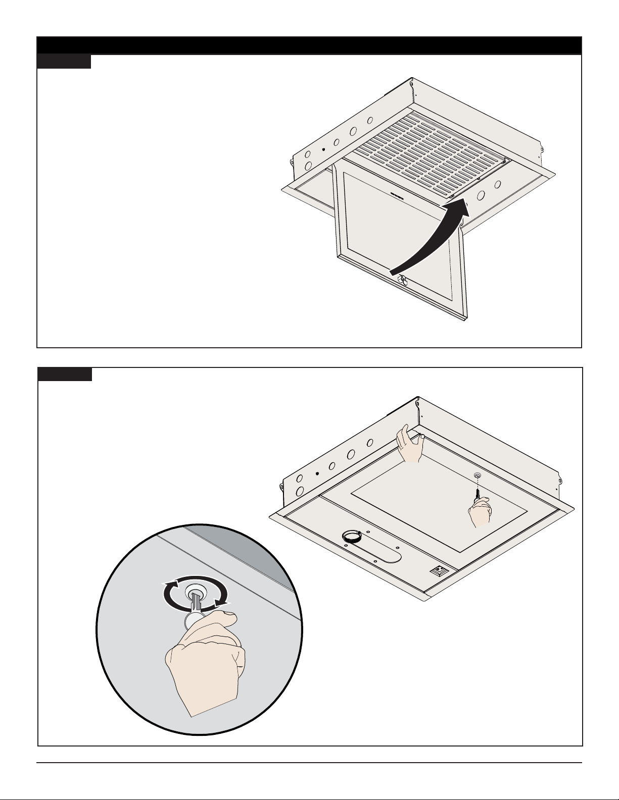
Securing the Lid
Step 1
1) Re-attach the ceiling box lid to the ceiling box.
2) Swing the ceiling box lid up into place.
Step 2
1) Hold the lid in place.
2) Use a key (supplied) to lock the lid in place.
3) Do not release the ceiling box lid until you are sure
that the lock has been engaged and the lid is secure.
Installation Instructions Page 13
premiermounts.com | p. 800.368.9700 | e. [email protected]
Page 14
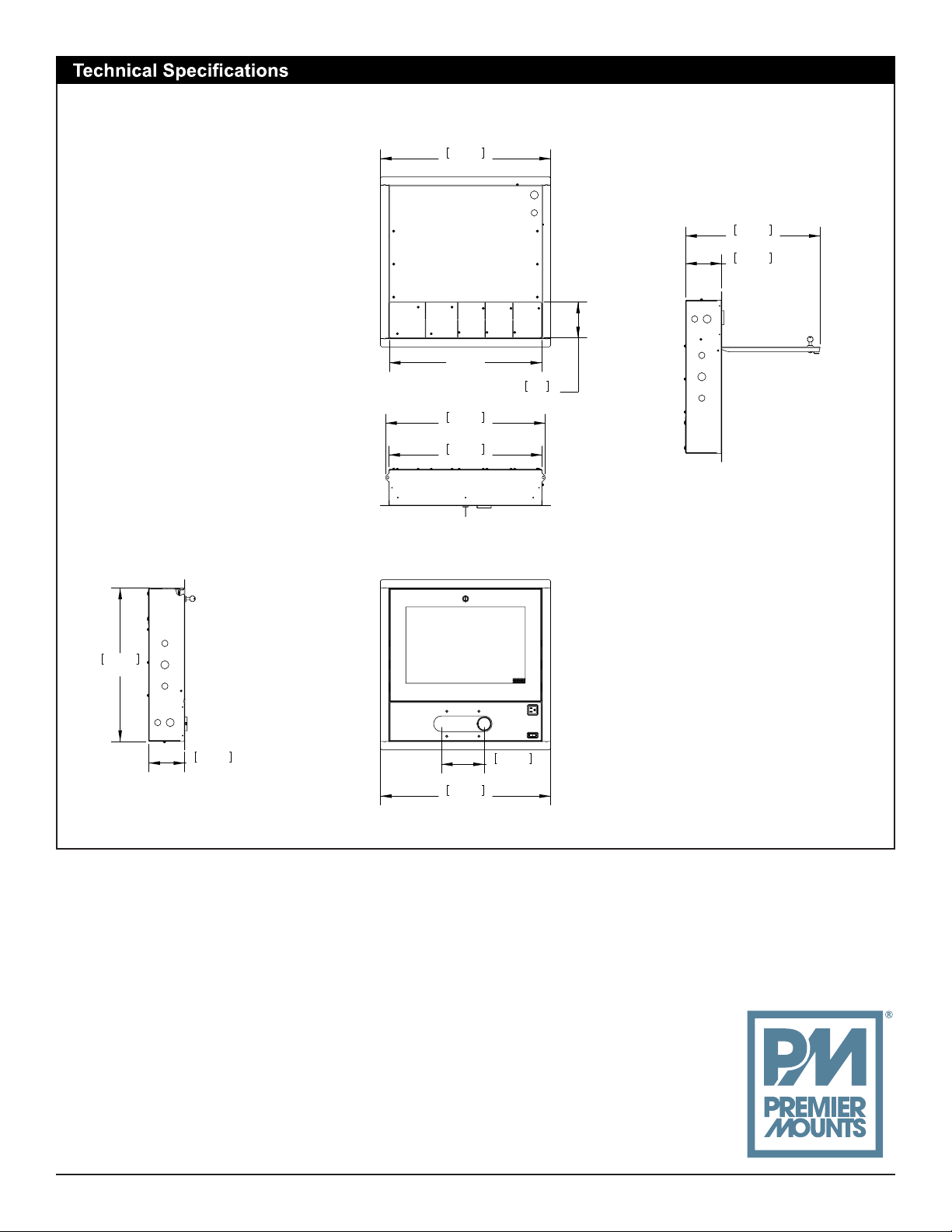
All measurements are in inches [mm].
606.43
23.875
21.348
568.71
22.390
546.10
21.500
127
5.000
479.01
18.859
128.21
5.048
546.10
21.500
128.21
5.05
PREMIER MOUNTS
©
500 W Central Ave, Suite A
Brea, CA 92821
USA & CANADA
Phone: 800-368-9700
Fax: 800-832-4888
606.43
23.875
152.40
6.000
Page 14 Installation Instructions
premiermounts.com | p. 800.368.9700 | e. [email protected]
 Loading...