

Page 1
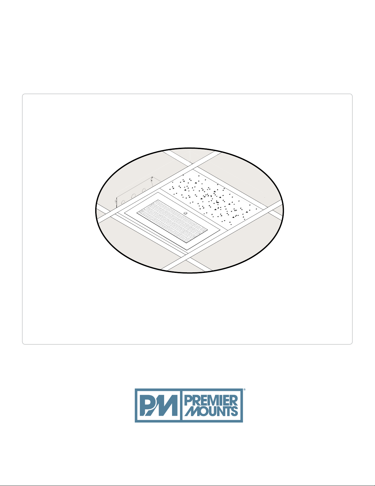
GB-AVSTOR4
Installation Guide
Installationsanleitung, Guía de Instalacíon, Guida de Installazione, Guide d’Installation, Installatie gids
premiermounts.com | p. 800.368.9700 | e. [email protected]
500 W Central Ave, Suite A, Brea, CA 92821 USA
Page 2
Weight Limit
Maximum Flat Panel Weight:
Warning Statements
PRIOR TO THE INSTALLATION OF THIS PRODUCT, THE INSTALLATION INSTRUCTIONS MUST BE READ AND COMPLETELY
UNDERSTOOD. KEEP THESE INSTALLATION INSTRUCTIONS IN AN EASILY ACCESSIBLE LOCATION FOR FUTURE REFERENCE.
PROPER INSTALLATION PROCEDURE BY A QUALIFIED SERVICE TECHNICIAN MUST BE FOLLOWED, AS OUTLINED IN THESE
INSTALLATION INSTRUCTIONS. FAILURE TO DO SO COULD RESULT IN PROPERTY DAMAGE, SERIOUS PERSONAL INJURY, OR
EVEN DEATH.
SAFETY MEASURES MUST BE PRACTICED AT ALL TIMES DURING THE ASSEMBLY OF THIS PRODUCT. USE PROPER SAFETY
EQUIPMENT AND TOOLS FOR THE ASSEMBLY PROCEDURE TO PREVENT PERSONAL INJURY.
PREMIER MOUNTS DOES NOT WARRANT AGAINST DAMAGE CAUSED BY THE USE OF ANY PREMIER MOUNTS PRODUCT FOR
PURPOSES OTHER THAN THOSE FOR WHICH IT WAS DESIGNED OR DAMAGE CAUSED BY UNAUTHORIZED ATTACHMENTS OR
MODIFICATIONS, AND IS NOT RESPONSIBLE FOR ANY DAMAGES, CLAIMS, DEMANDS, SUITS, ACTIONS OR CAUSES OF ACTION
OF WHATEVER KIND RESULTING FROM, ARISING OUT OF OR IN ANY MANNER RELATING TO ANY SUCH USE, ATTACHMENTS OR
MODIFICATIONS.
50 lbs.
THE CEILING STRUCTURE MUST BE CAPABLE OF SUPPORTING AT
LEAST FOUR TIMES THE WEIGHT OF THE CEILING BOX. IF NOT,
THE CEILING STRUCTURE MUST BE REINFORCED.
This product is intended for indoor use only. Use of this product outdoors could lead to product failure and/or serious personal injury.
Do not install near sources of high heat. Do not install on a structure that is prone to vibration, movement or chance of impact.
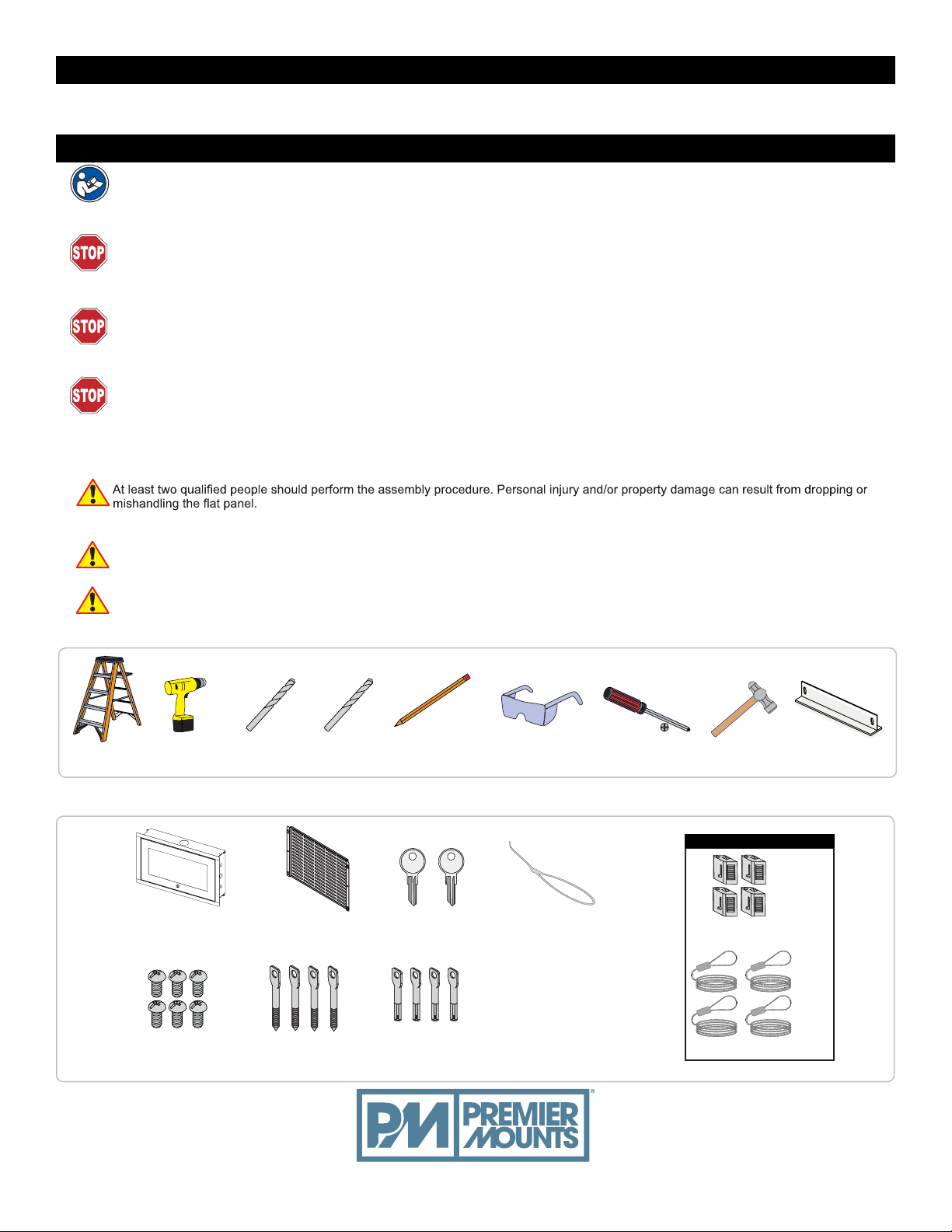
Required for installation
Ladder
Drill Gun
1/4" Concrete
Drill bit
Included components
x 1
GB-AVSTOR4
Ceiling Box
x 6 x 4
1/8" Drill bit
Equipment
Mounting Tray
x 1
Pencil
Keys
Protective Eyewear
x 2 x 12
Zip Ties
x 4
Phillips Screwdriver
Hammer
Quick Lock Cable Kit
24" T-Bar Frame
x 4
Quick Locks
x 4
M5 x 8mm Phillips
Head Screw
1/4" x 3” Eye
Lag Screws
Eye Anchor Bolts
1/16" Braided Cable
premiermounts.com | p. 800.368.9700 | e. [email protected]
Page 3
GB-AVSTOR4
Installation Guide
Installationsanleitung, G uía de Instalací on, Guida de Installaz ione, Guide d’ Inst allation, Installatie g ids
Features
The GB-AVSTOR4 Ceiling Equipment Storage GearBox™ is a secure and discreet storage solution. Simply replace half
of a standard 2’ x 2’ ceiling tile with the GB-AVSTOR4 to hide your electronic and electrical components above the room.
The perforated lid looks like a standard HVAC return register when closed to blend in with the rest of the ceiling.
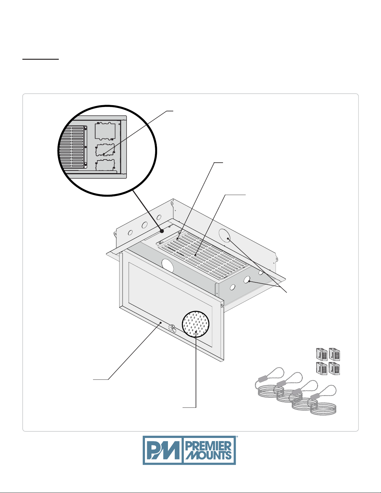
Power and Signal Knockouts
Multiple, single and dual-gang knockouts
(knockout covers not
Inside View
shown)
Removable Equipment Tray
Tray allows components to be
pre-wired prior to installation
Mounting Slots
Allows you to attach a
variety of A/V equipment
Security
Lockable access panel
keeps A/V gear safe
premiermounts.com | p. 800.368.9700 | e. [email protected]
Perforated Lid
Looks like standard HVAC return
ter when closed to stay unobtrusive
regis
Knockouts
2”, 1” and 3/4” knockouts provide
electrical conduit connector access
Includes the Quick Lock Cable Kit
Page 4
GB-AVSTOR4
Installation Guide
Installationsanleitung, Guía de Instalacíon, G uida de Installazione, Guide d ’Installation, Installatie gids
Introduction
Please read these installation instructions thoroughly before installing your Premier Mounts product.
Please take a minute to familiarize yourself with the contents of the package and make sure you have all the parts and tools you need to
safely complete the installation.
In addition, some steps of this installation may require two people to prevent personal injury and/or damage to your equipment. Please
observe all warnings in the following installation procedure and utilize proper safety equipment at all times.
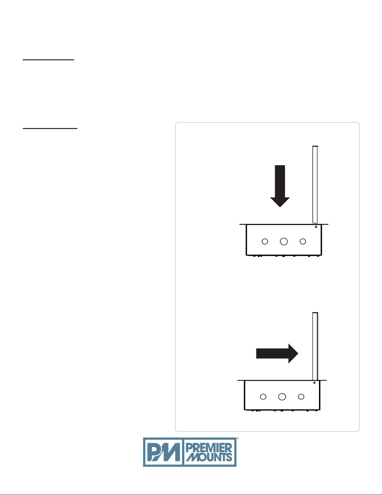
Lid Removal
1. Unlock and swing up the lid.
2. Push the lid in and away from
the metal hinges (Figure 1).
3. Push the lid toward the closest edge
of the ceiling box (Figure 2).
4. Pull the lid carefully out from the ceiling
box.
Figure 1
Ceiling Box Side View
Figure 2
premiermounts.com | p. 800.368.9700 | e. [email protected]
Page 5
Installationsanleitung, G uía de Instalací on, Guida de Installaz ione, Guide d’ Inst allation, Installatie g ids
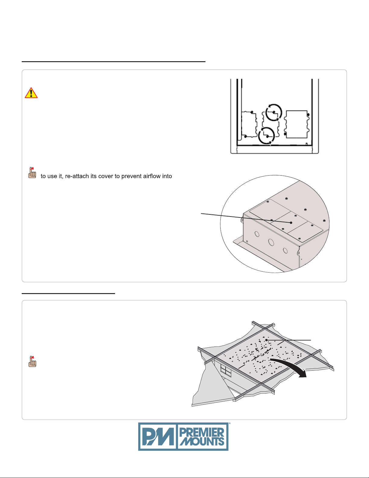
Removing the Electrical Knockouts (Optional)
Installation of the power must be done by an
electrician
Remove screws from around the desired electrical
Knockouts (Figure 1) to detach their covers.
Remove the knockout covers from the top of the
GB-AVSTOR4 (Figure 2).
Remove the knockouts.
If you have opened a knockout and no longer want
the ceiling.
Detach the knockout
cover after removing
its screws.
GB-AVSTOR4
Installation Guide
Figure 1
Ceiling Box Installation
1. Determine the desired placement of the
GB-AVSTOR4.
2. Cut and remove half of the ceiling tile where the
ceiling box will be mounted.
Store the half-ceiling tile in a safe location in the
event that it needs to be reused.
Figure 2
Ceiling Tile
premiermounts.com | p. 800.368.9700 | e. [email protected]
Page 6
GB-AVSTOR4
Installation Guide
Installationsanleitung, G uía de Instalací on, Guida de Installaz ione, Guide d’ Inst allation, Installatie g ids
Ceiling Attachment
The ceiling box must be secured using the Quick Lock and 1/16" braided cables (supplied).
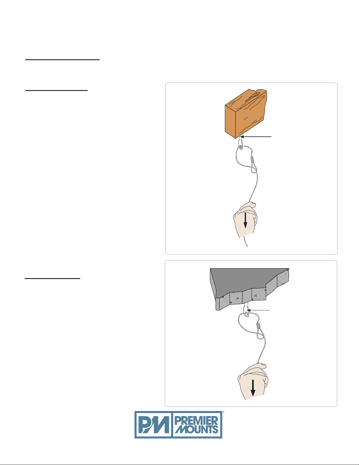
Wood Stud Ceiling
1. Determine the mounting location.
2. Use a 1/8" drill bit to pre-drill the mounting holes.
3. Secure the four (4) 1/4" eye lag screws to the
wood stud in the ceiling.
4. Run the open end of the 1/16" braided cable
through the hole in an eye lag screw.
5. Run the open end through the loop.
6. Pull the open end down until the 1/16" braided
cable tightens around the eye lag screw.
7. Repeat steps 4-6 for the remaining three
mounting points.
Eye Lag Screw
Concrete Ceiling
1. Determine the mounting location.
2. Use a 1/4" concrete drill bit to drill the mounting
holes.
3. Place the concrete eye anchor bolts into the
pre-drilled holes and gently tap into place using
a rubber mallet or hammer.
4. Run the open end 1/16" braided cable through
the hole in an eye anchor bolt.
5. Run the open end through the loop.
6. Pull the open end down until the braided cable
tightens around the eye anchor bolt.
7. Repeats steps 4-6 for the remaining three
mounting points.
premiermounts.com | p. 800.368.9700 | e. [email protected]
Eye Anchor Bolt
Page 7
Installationsanleitung, G uía de Instalací on, Guida de Installaz ione, Guide d’ Inst allation, Installatie g ids
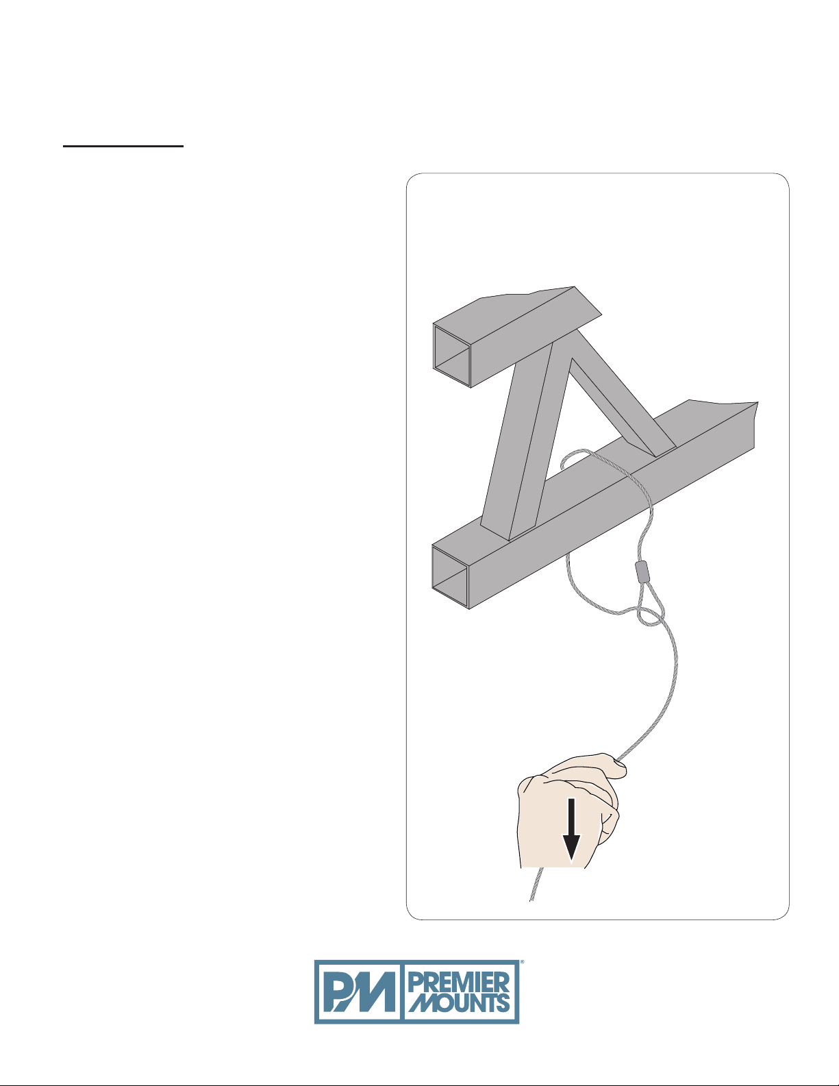
Truss Ceiling
1. Loop the braided cable around the truss.
2. Run the open end 1/16" braided cable
through the loop.
3. Pull the open end down until the 1/16"
braided cable tightens around the truss.
4. Repeat steps 1-3 for the remaining three
mounting points.
GB-AVSTOR4
Installation Guide
Ceiling Truss
premiermounts.com | p. 800.368.9700 | e. [email protected]
Page 8
GB-AVSTOR4
Installation Guide
Installationsanleitung, G uía de Instalací on, Guida de Installaz ione, Guide d’ Inst allation, Installatie g ids
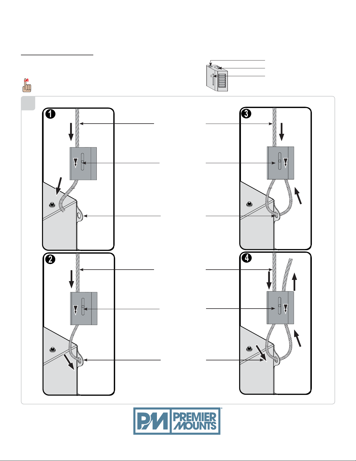
Quick Lock Operation
Please follow the steps below in numerical order (1), (2), (3),
and (4) to correctly install the Quick Lock Cable Kit.
To release or relieve tension on the 1/16" braided cable,
slide the release pin to disengage.
1
1/16" Braided Cable
Release Pin
Cable Output
Cable Input
Release Pin
Mounting Hole
1/16" Braided Cable
Release Pin
Mounting Hole
premiermounts.com | p. 800.368.9700 | e. [email protected]
Page 9
2
GB-AVSTOR4
Installation Guide
Installationsanleitung, G uía de Instalací on, Guida de Installaz ione, Guide d’ Inst allation, Installatie g ids
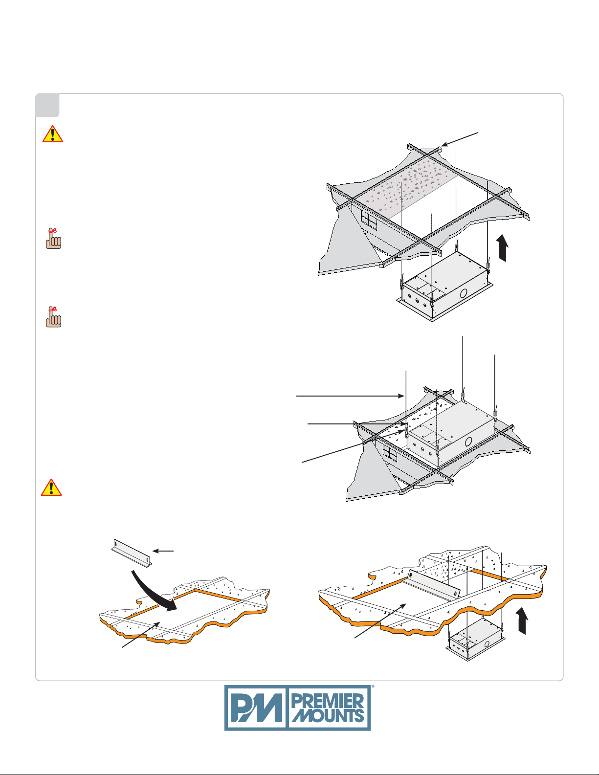
It is recommended that the following steps be
performed by two people.
1. Lift the ceiling box from the exposed ceiling frame
work until the ceiling box's outer lip rests against the
bottom of the ceiling framework (Figure1).
2. Adjust the 1/16" braided cable tension, but do not
over tighten.
When adjusting the tension of the weight-bearing
side of the Quick Lock, the 1/16" braided cable must be pulled
through the Quick Lock until the desired
tension is attained.
3. When you have the desired tension, pull the 1/16" braided
cable through the other side of the Quick Lock.
Once the tension has been adjusted, be sure that there is a
minimum of 6" of excess 1/16" braided cable on the non-weight
bearing side of the Quick Lock.
4. Use cutters to remove any remaining 1/16" braided cable
(optional).
1/16" Braided
Cable To Ceiling
Attachment
6" Excess 1/16"
Braided Cable
Ceiling Framework
Figure 1
Quick Lock
If you are installing the GB-AVSTOR4 through a
24" x 48" ceiling tile opening, attach a 24" T-bar frame
(commerically available) in the 24" x 48" ceiling tile frame
for support and place a 2' x 2' ceiling tile adjacent to the
GB-AVSTOR4 (Figure 3 and 4).
24" T-Bar Frame
24" x 48" Ceiling Tile
Opening
premiermounts.com | p. 800.368.9700 | e. [email protected]
Figure 3
The replacement 2' x 2'
ceiling tiles goes here.
Figure 2
Figure 4
Page 10
GB-AVSTOR4
Installation Guide
Installationsanleitung, G uía de Instalací on, Guida de Installaz ione, Guide d’ Inst allation, Installatie g ids
Mounting Tray Installation
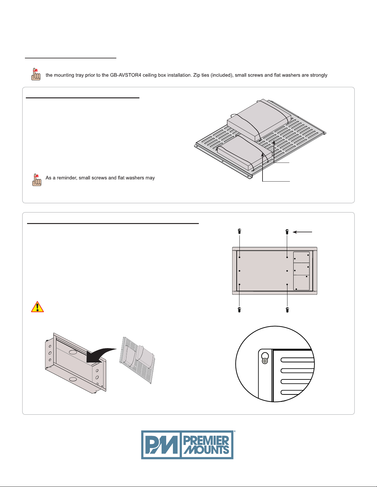
For ease of installation, the mounting tray comes packaged in a separate box within the master carton. Installers may pre-wire
recommended to hold all equipment in place.
Attaching Equipment to the Tray
1. Place your electronic components onto the
mounting tray.
2. Align the electronic components so that the
weight is distributed as evenly as possible.
3. Run the zip ties through the mounting slots on
the tray, underneath the mounting tray and up
through the mounting slot on the other side of the
electronic components.
4. Tighten the zip tie down and cut off any excess
zip tie.
Mounting Tray
also be used to attach electronic components to the grid.
Attaching the Mounting Tray to the GB-AVSTOR4
1. Insert four (4) M5 x 8mm Phillips head screws loosely into the
outer holes inside the GB-AVSTOR4 (Figure 1).
2. Place the mounting tray into the middle section of the
GB-AVSTOR4 (Figure 2).
3. Hook the mounting tray onto the heads of the M5 x 8mm Phillips
head screws on the GB-AVSTOR4 (Figure 3).
4. Insert two (2) M5 x 8mm Phillips head screws into the middle
mounting holes of the mounting tray.
5. Use a Phillips tip screwdriver to tighten all six (6) screws.
Do not overtighten the mounting screws.
Zip Tie
M5 x 8mm Phillips
head screw
Figure 1
Figure 2
premiermounts.com | p. 800.368.9700 | e. [email protected]
Figure 3
Page 11
Securing the Lid
GB-AVSTOR4
Installation Guide
Installationsanleitung, G uía de Instalací on, Guida de Installaz ione, Guide d’ Inst allation, Installatie g ids
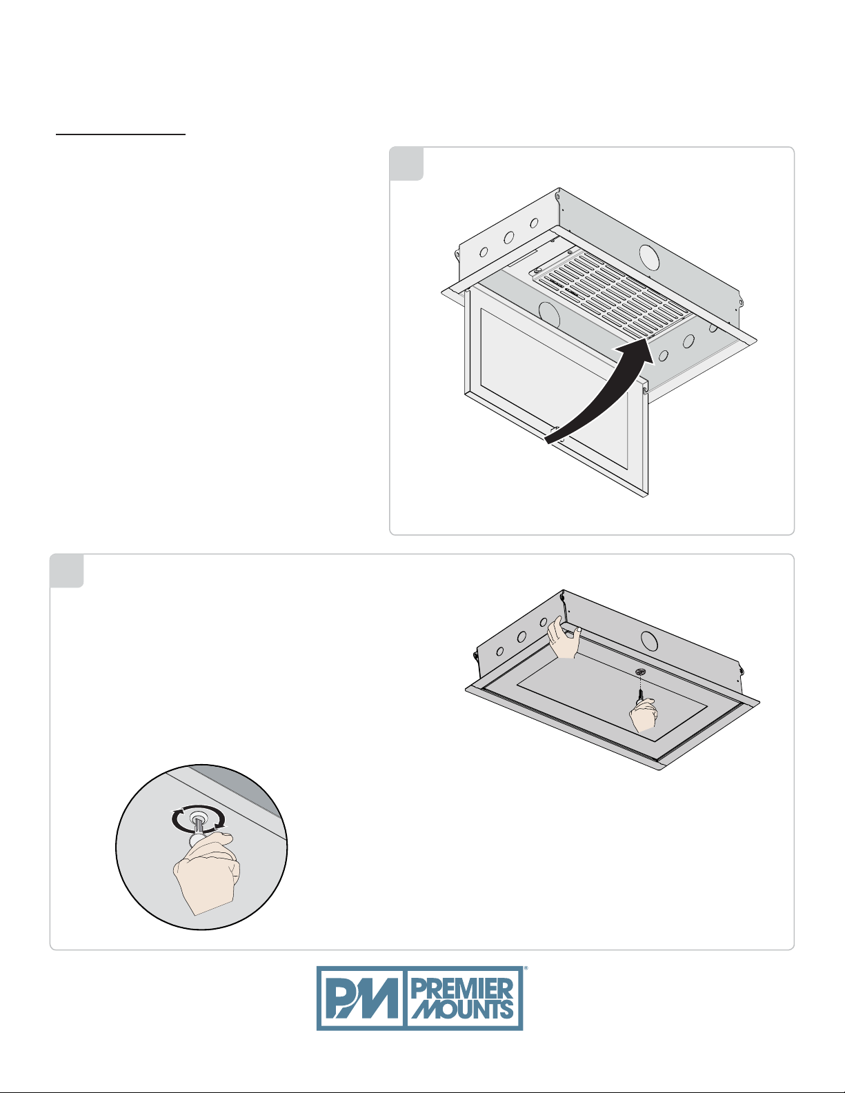
1. Re-attach the ceiling box lid to the ceiling box.
2. Swing the ceiling box lid up into place.
1
2
1. Hold the lid in place.
2. Use a key (supplied) to lock the lid in place.
3. Do not release the ceiling box lid until you are
sure that the lock has been engaged and the lid
is secure.
premiermounts.com | p. 800.368.9700 | e. [email protected]
Page 12
GB-AVSTOR4
Installation Guide
Installationsanleitung, G uía de Instalací on, Guida de Installaz ione, Guide d’ Inst allation, Installatie g ids
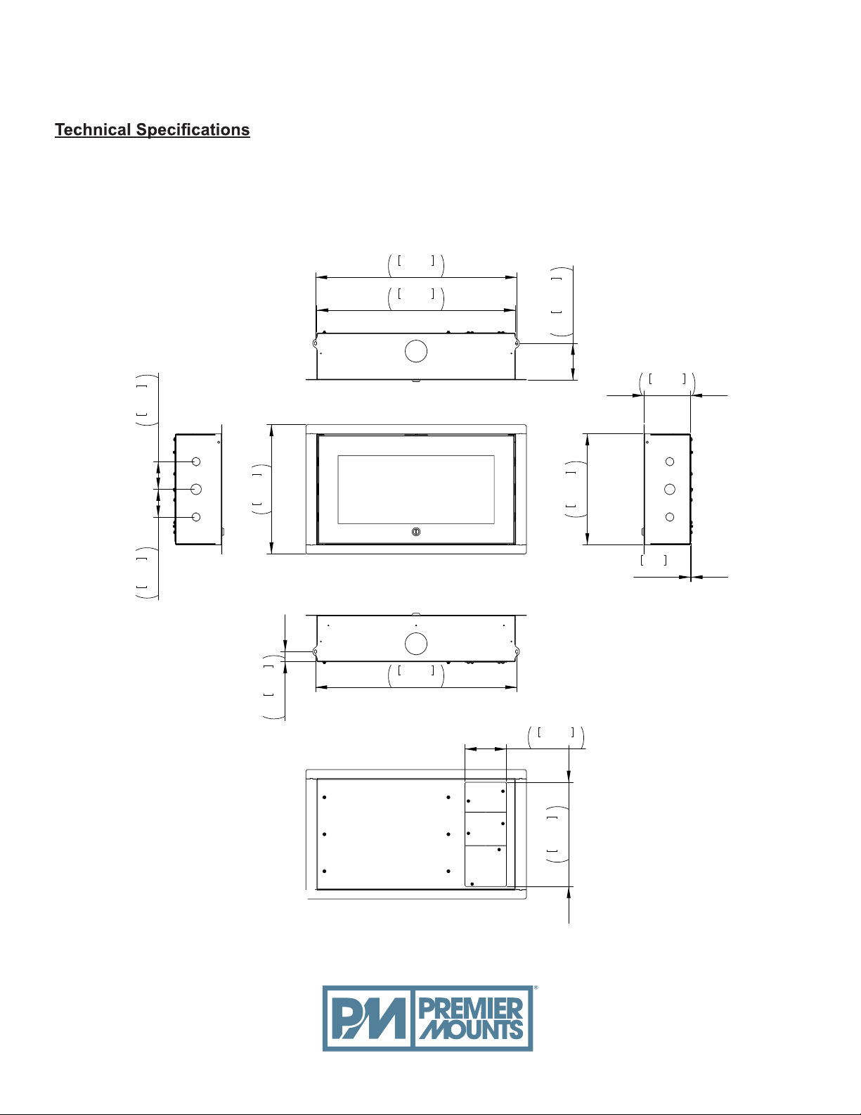
All measurements are in inches (mm).
553.47
21.790
546.10
21.500
3.000
76.20
3.946
100.23
2x
128.21
5.048
3.000
76.20
14.000
355.60
27.98
2x 1.102
553.47
21.790
114.30
4.500
286.51
304.80
11.280
12.000
1.21
.048
premiermounts.com | p. 800.368.9700 | e. [email protected]
 Loading...