

Page 1
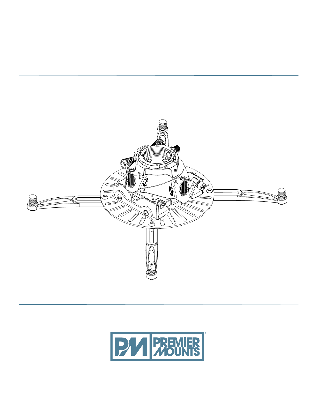
Fine Tune Projector Mount
Model: FTP / FTPW
INSTALLATION INSTRUCTIONS
premiermounts.com | p. 800.368.9700 | e. [email protected]
500 W Central Ave, Suite A, Brea, CA 92821 USA
9530-090-001-0C
Page 2

Fine Tune Projector Mount
Contents
Weight Limit. .................................................................................................................................................................................................2
Warning Statements. .....................................................................................................................................................................................2
Installation Tools. ..........................................................................................................................................................................................3
Parts List. ........................................................................................................................................................................................................3
Mounting Hardware. .....................................................................................................................................................................................4
Lock-It™ Security Hardware Pack. ...............................................................................................................................................................4
Features. ..........................................................................................................................................................................................................5
Installing the Fine Tune Projector Mount. .................................................................................................................................................6
Introduction. ..................................................................................................................................................................................6
Pipe Installation. ............................................................................................................................................................................6
Wood Stud Installation. ................................................................................................................................................................8
Attaching the Universal Projector Plate. ..................................................................................................................................................10
Selecting the Mounting Hardware.............................................................................................................................................10
Multiple Mount Point Installation. ............................................................................................................................................11
Single Mount Point Installation. ................................................................................................................................................13
Securing the Quick Set Base. .....................................................................................................................................................................14
Attaching the Projector to the Mount.......................................................................................................................................................14
Alignment & Fine-Tuning. .........................................................................................................................................................................15
Locking in the Adjustments. ......................................................................................................................................................................16
Securing the Fine Tune Projector Mount. ................................................................................................................................................16
.............................................................................................................................................................................17
Warranty. ......................................................................................................................................................................................................18
Disclaimer. ....................................................................................................................................................................................................18
Weight Limit
THE CEILING STRUCTURE MUST BE CAPABLE OF
Maximum Projector Weight:
65 lbs.
SUPPORTING AT LEAST FIVE TIMES THE WEIGHT OF THE
PROJECTOR. IF NOT, THE CEILING STRUCTURE MUST BE
REINFORCED.
Warning Statements
PRIOR TO THE INSTALLATION OF THIS PRODUCT, THE INSTALLATION INSTRUCTIONS MUST BE READ AND
COMPLETELY UNDERSTOOD. KEEP THESE INSTALLATION INSTRUCTIONS IN AN EASILY ACCESSIBLE LOCATION FOR
FUTURE REFERENCE.
PROPER INSTALLATION PROCEDURE BY A QUALIFIED SERVICE TECHNICIAN MUST BE FOLLOWED, AS OUTLINED IN
THESE INSTALLATION INSTRUCTIONS. FAILURE TO DO SO COULD RESULT IN PROPERTY DAMAGE, SERIOUS PERSONAL
INJURY, OR EVEN DEATH.
SAFETY MEASURES MUST BE PRACTICED AT ALL TIMES DURING THE ASSEMBLY OF THIS PRODUCT. USE PROPER SAFETY
EQUIPMENT AND TOOLS FOR THE ASSEMBLY PROCEDURE TO PREVENT PERSONAL INJURY.
PREMIER MOUNTS DOES NOT WARRANT AGAINST DAMAGE CAUSED BY THE USE OF ANY PREMIER MOUNTS PRODUCT
FOR PURPOSES OTHER THAN THOSE FOR WHICH IT WAS DESIGNED OR DAMAGE CAUSED BY UNAUTHORIZED
ATTACHMENTS OR MODIFICATIONS, AND IS NOT RESPONSIBLE FOR ANY DAMAGES, CLAIMS, DEMANDS, SUITS,
ACTIONS OR CAUSES OF ACTION OF WHATEVER KIND RESULTING FROM, ARISING OUT OF OR IN ANY MANNER
RELATING TO ANY SUCH USE, ATTACHMENTS OR MODIFICATIONS.
mishandling the projector.
If mounting to ceiling studs, make sure that the mounting screws are anchored into the center of the ceiling studs. Use of an edge-to-edge
Do not install near sources of high heat. Do not install on a structure that is prone to vibration, movement or chance of impact.
Page 2 Installation Instructions
premiermounts.com | p. 800.368.9700 | e. [email protected]premiermounts.com | p. 800.368.9700 | e. [email protected]
Page 3
Fine Tune Projector Mount
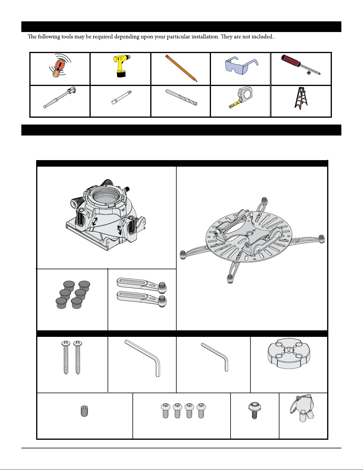
Installation Tools
Electronic Stud Finder
Socket Wrench
Hand Held Drill
Socket Wrench Extension
Pencil Protective Eyewear
⅛˝ Wood Drill Bit
Tape Measure
Q
P
Phillips Tip Screwdriver
Ladder
Parts List
Make sure your Premier Mounts product has the following hardware and components before beginning installation.
Fine Tune Projector Mount Hardware
FTP Dome
(Qty 1)
Barrel Caps
(Qty 6)
˝ Wood
#14 x 3
Screws (Qty 2)
M6 x 6mm Security Set Screw
(Qty 1)
Mounting Legs - Short
(Qty 2)
Fine Tune Projector Base Box Mounting Hardware
M5 Allen
Wrench (Qty 1)
M3 Security Allen
Wrench (Qty 1)
M6 x 8mm Security Screw
(Qty 4)
Universal Projector Plate
With Four Pre-installed Legs
(Qty 1)
Installation Disk
(Qty 1)
Keylock Screw
(Qty 1)
Keylock Key
(Qty 2)
Installation Instructions Page 3
premiermounts.com | p. 800.368.9700 | e. [email protected]
Page 4
Fine Tune Projector Mount
Parts List (cont’d)
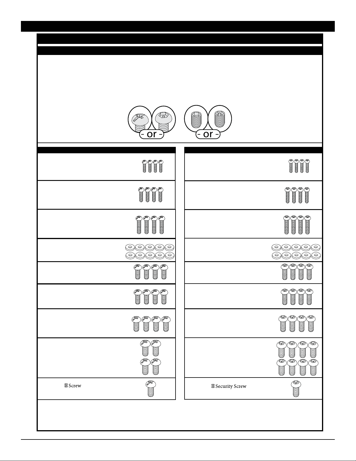
Mounting Hardware
Lock-It™ Security Hardware Pack
Your Premier Mounts Fine Tune Projector Mount comes with the option of using Lock-It™ Security Screws. Simply
replace any of the Phillips head screws with the corresponding sized Lock-It™ Security Screws and tighten using the
appropriate size Allen wrench.
When you see the graphics below associated with a step, you have the option of using the standard mounting hardware
or the Lock-It Security hardware.
Standard Hardware Lock-It™ Security Hardware
M2.5 x 10mm Screw
(Qty 4)
M2.5 x 12mm Screw
(Qty 4)
M3 x 16mm Screw
(Qty 4)
M3 Flat Washer
(Qty 10)
M4 x 10mm Screw
(Qty 4)
M4 x 12mm Screw
(Qty 4)
M5 x 12mm Screw
(Qty 4)
M2.5 x 10mm Security Screw
(Qty 4)
M2.5 x 12mm Security Screw
(Qty 4)
M3 x 16mm Security Screw
(Qty 4)
M3 Flat Washer
(Qty 10)
M4 x 10mm Security Screw
(Qty 4)
M4 x 12mm Security Screw
(Qty 4)
M5 x 12mm Security Screw
(Qty 4)
M6 x 12mm Screw
(Qty 4)
5
/16
¼-20 x
(Qty 1)
Page 4 Installation Instructions
premiermounts.com | p. 800.368.9700 | e. [email protected]
M6 x 12mm Security Screw
(Qty 8)
¼-20 x 5/16
(Qty 1)
Page 5
Fine Tune Projector Mount
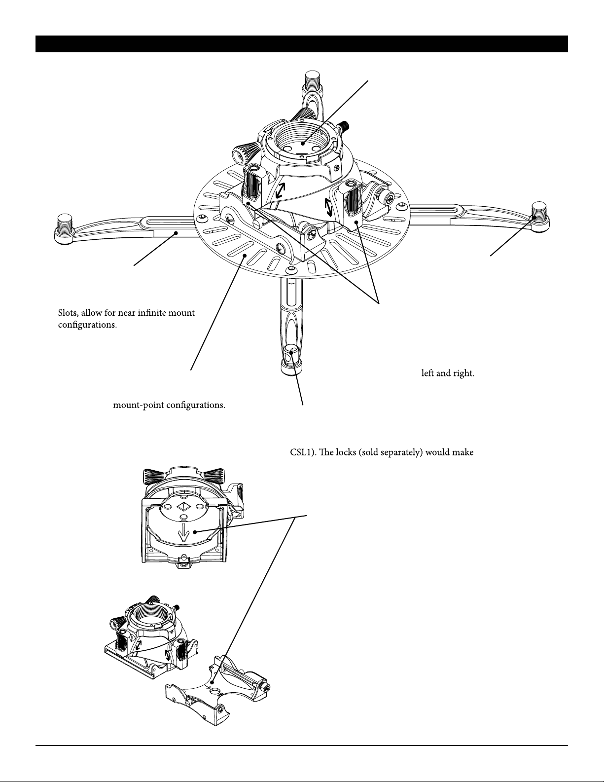
Features
Multiple Mounting Options
You can install your Fine Tune Projector mount to
1½˝ NPT pipe or a ceiling stud.
Lock-It™ Security Hardware
Protect your projector by
installing specialized hardware at
critical mounting points.
Installation Disk
Versatile tool allows you to rapidly install your
Fine Tune Projector mount on to 1½˝ NPT pipe
by using a socket wrench and socket wrench
extension, or you can use it as a mounting
bracket for ceiling stud installation.
Mounting Legs
Both long and short mounting
legs, combined with the numerous
Universal Projector Plate Mounting
Mounting Slots
Allows you to choose from a variety
of mounting options and projector
Adjustable Leveling Barrels
You can quickly level the mounting legs without
any specialized tools.
Fine-Tune Controls
Without needing any tools to loosen
mounting hardware, you can adjust:
Roll up to 5˚ to either side.
Pitch up to 15˚ down and 5˚ up.
Yaw up to 20˚
Security Leveling Barrel
Allows the user to easily secure the mount with
a padlock or a steel-cable locking system (PCB-
it nearly impossible for anyone to remove the
projector from the mount.
Projector Direction Arrows
Inscribed on the underside of the FTP Dome and on
the top of the Quick Set Base, you can always know
for certain which way your projector will be pointing
while you are installing your Fine-Tune Projector
mount.
Quick Set Base
If your projector ever needs service, you can
quickly detach and attach it without having to
uninstall the entire mount or re-align the projector
to the screen.
Installation Instructions Page 5
premiermounts.com | p. 800.368.9700 | e. [email protected]
Page 6
Fine Tune Projector Mount
Installing the Fine Tune Projector Mount
Introduction
adapter, or a single ceiling stud. If using an optional Premier Mounts adapter, please refer to the installation instructions that come
with each adapter on the proper installation of that product.
Please read these installation instructions once thoroughly before attempting to install your Premier Mounts product.
Please take a minute to familiarize yourself with the contents of the package and make sure you have all the parts and tools you
need to safely complete the installation.
In addition, some steps of this installation may require two people
to prevent personal injury and/or damage to your projector.
Please observe all warnings in the following installation procedure and utilize proper safety equipment at all times.
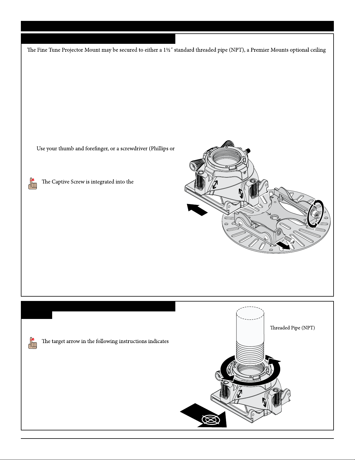
Begin installing your Fine Tune Projector mount by separating the FTP Dome from the Quick Set Base.
1) Use Phillips screwdriver to remove the M5 x 12mm screw.
Place the M5 x 12mm Key Key Lock Screw in a safe
location.
2)
slotted), to loosen the Captive Screw.
3) Separate the FTP Dome and the Quick Set Base / Universal
FTP Dome
Projector Plate.
Quick Set Base
and may not be removed.
If you are installing your FTP mount to a 1½˝ NPT pipe,
proceed to the “Pipe Installation” section.
If you are installing your FTP mount to a wood stud, skip to the
“Wood Stud Installation” section.
Quick Set Base / Universal
Projector Plate
M5 x 12mm Screw
Captive
Screw
Pipe Installation
Step 1
Hand-thread the FTP Dome onto the 1½˝ standard threaded
pipe (NPT) until it is hand-tight.
the direction of the projector screen relative to the
projector mount.
Page 6 Installation Instructions
premiermounts.com | p. 800.368.9700 | e. [email protected]
1½˝ Standard
Page 7
Fine Tune Projector Mount
Installing the Fine Tune Projector Mount (cont’d)
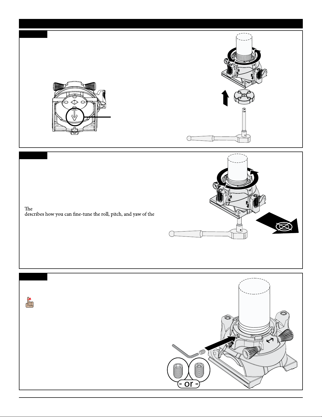
Step 2
1) Attach a 6˝ or longer socket wrench extension onto a socket
wrench.
2) Insert the end of the socket wrench extension into the
center of the Installation Disk, then insert the Installation
Disk into the underside of the FTP Dome.
Note the arrow inscribed inside of the FTP Dome.
Inscribed Arrow
FTP Dome as Viewed from Below
Step 3
Tighten the FTP Dome until the inscribed arrow on the
underside of the FTP Dome points in the direction in which the
projector will be facing.
If the FTP Dome becomes too tight to turn and the inscribed
arrow is pointing away from the projector screen by more than
5˚, loosen the FTP Dome one (1) rotation until the inscribed
arrow points towards the projector screen.
“Alignment & Fine-Tuning” section of this manual
projector.
Remove the Installation Disk and store it in a safe location.
Step 4
Secure the FTP Dome to the pipe with one (1) M6 x 6mm set
screw and tighten it using the M3 Allen wrench.
You can use either the standard hardware or Lock-It™
security hardware.
Proceed to the “Attaching the Universal Projector Plate”
section.
Installation Instructions Page 7
premiermounts.com | p. 800.368.9700 | e. [email protected]
Page 8
Installing the Fine Tune Projector Mount (cont’d)
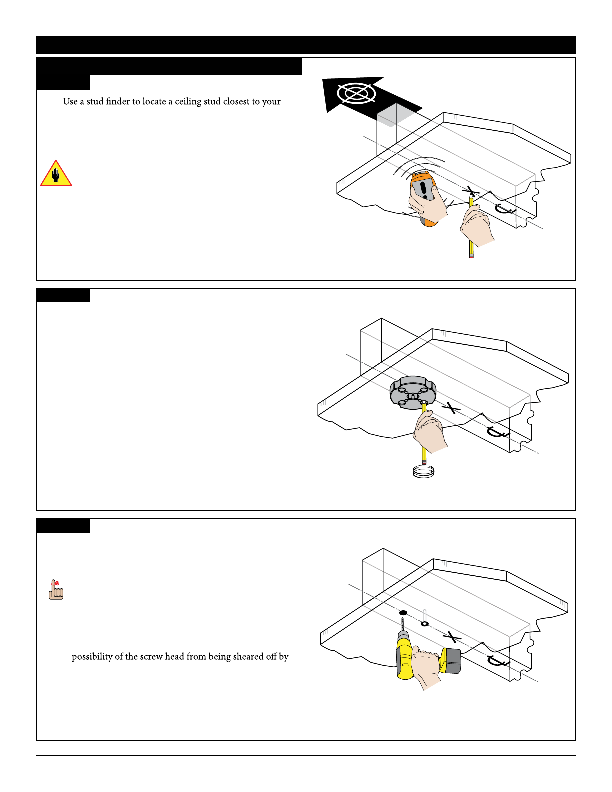
Wood Stud Installation
Step 1
1)
desired installation location.
2) Identify the center of the ceiling stud.
3) Use a pencil to mark the location of the ceiling stud center.
Be sure to only install on ceiling with a max drywall
thickness of 5/8”.
Step 2
1) Place the Installation Disk against the ceiling with the
mounting holes aligned with the center of the ceiling stud.
2) Use a pencil and mark two (2) mounting hole locations
through the holes in the Installation Disk.
Fine Tune Projector Mount
Stud
Center
Step 3
Remove the Installation Disk and set it aside.
Drill a pilot hole in the center of each mark using a power drill
1
and
/8˝ drill bit.
Pilot Holes
When a screw is driven into a material, such as wood, it
can act as a wedge, generating outward pressure which
can cause many materials to split. Drilling a small pilot
hole in the material into which the screw will be driven
causes less ‘wedging’ to take place, thereby reducing the
likelihood of the material being split. It also reduces the
torque.
Page 8 Installation Instructions
premiermounts.com | p. 800.368.9700 | e. [email protected]
Page 9
Fine Tune Projector Mount
Installing the Fine Tune Projector Mount (cont’d)
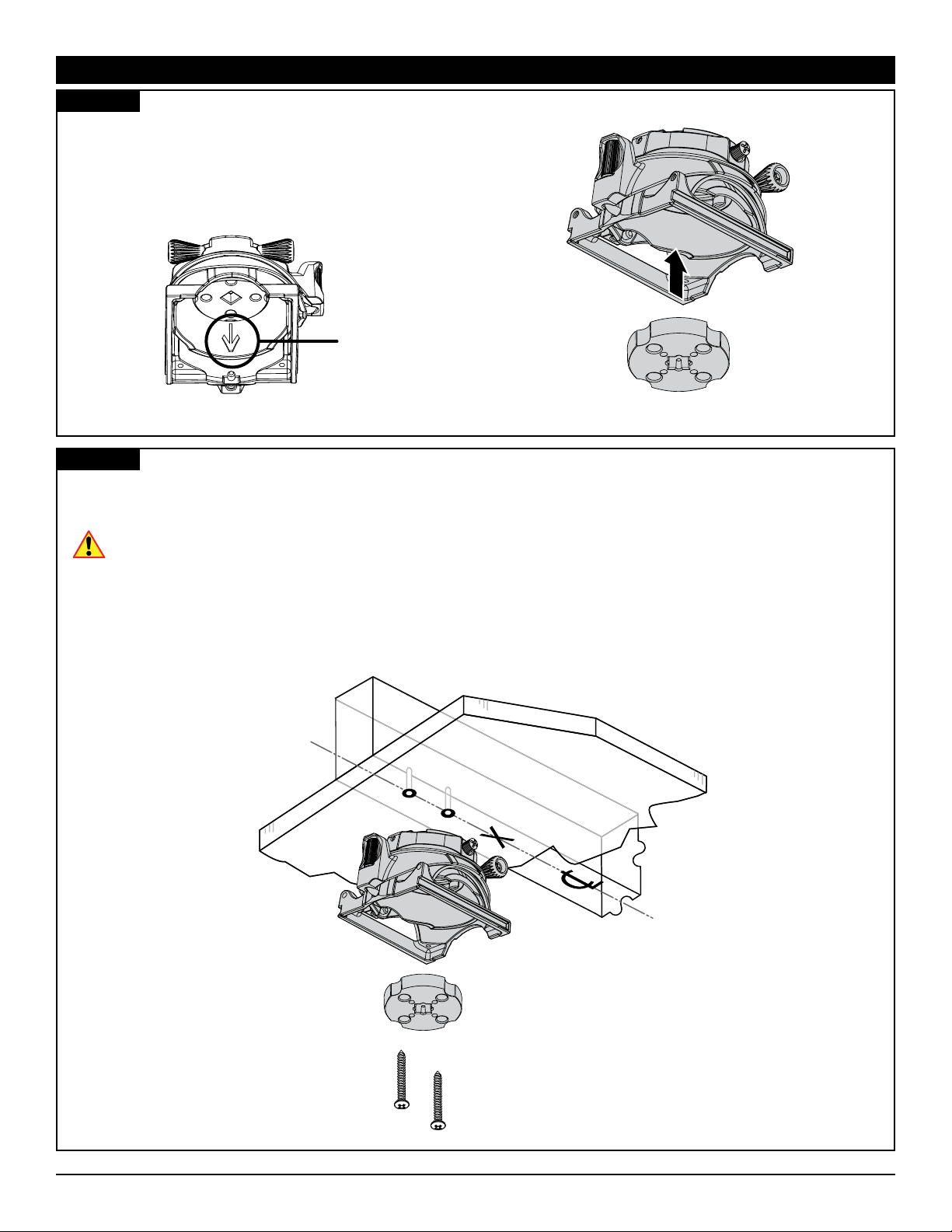
Step 4
Insert the Installation Disk into the underside of the FTP
Dome.
Note the arrow inscribed inside of the FTP Dome; make sure
that it is pointed in the same direction that your projector will
be pointed.
Inscribed Arrow
FTP Dome as Viewed from Below
Step 5
1) Insert one (1) #14 x 3˝ screw through each of the holes in the bottom of the Installation Disk and into the pilot holes.
2) Tighten each screw until the FTP Dome and Installation Disk are secure against the ceiling.
Do not overtighten the mounting screws.
Proceed to the “Attaching the Universal Projector Plate” section.
Installation Instructions Page 9
premiermounts.com | p. 800.368.9700 | e. [email protected]
Page 10
Attaching the Universal Projector Plate
Selecting the Mounting Hardware
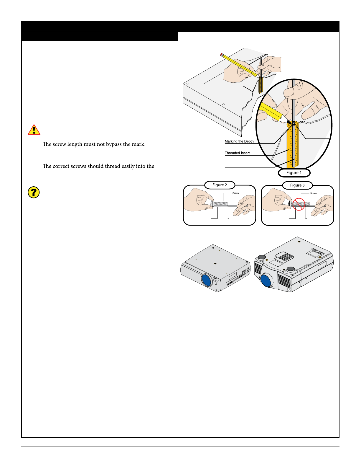
1) Insert a small straw or toothpick into the threaded inserts
found on the bottom or top of the projector.
2) Use a pencil to mark the depth of the threaded insert on the
small straw or toothpick.
3) Mark the straw or toothpick 1/8” above the depth of the
threaded insert, as shown in Figure 1.
4) Insert the small straw or toothpick into the remaining
threaded inserts to compare and verify their depth using
the straw or toothpick’s 1/8” allowance mark.
5) Locate the correct diameter screw for the threaded insert.
Fine Tune Projector Mount
If the screw you selected is longer than the 1/8”
allowance mark on the small straw or toothpick, as
shown in Figure 2 and Figure 3, do not use this screw.
6) Test each size of the screws provided.
mounting point and not pull out when tension is applied.
Does your projector have multiple mount points or a
single mount point?
If your projector has multiple mount points, proceed to
the “Multiple Mount Point Installation” section.
If your projector has a single mount point, remove
the pre-installed mounting legs on the universal
projector plate and skip to the “Single Mount Point
Installation” section.
Small Straw
or Toothpick
Small Straw or Toothpick
Depth Plus 1/8” Allowance
Mark
Small Straw
or Toothpick
Marking the 1/8”
Allowance
Depth Plus 1/8” Allowance
Mark
Page 10 Installation Instructions
premiermounts.com | p. 800.368.9700 | e. [email protected]
Page 11
Fine Tune Projector Mount
Attaching the Universal Projector Plate (cont’d)
Multiple Mount Point Installation
Step 1
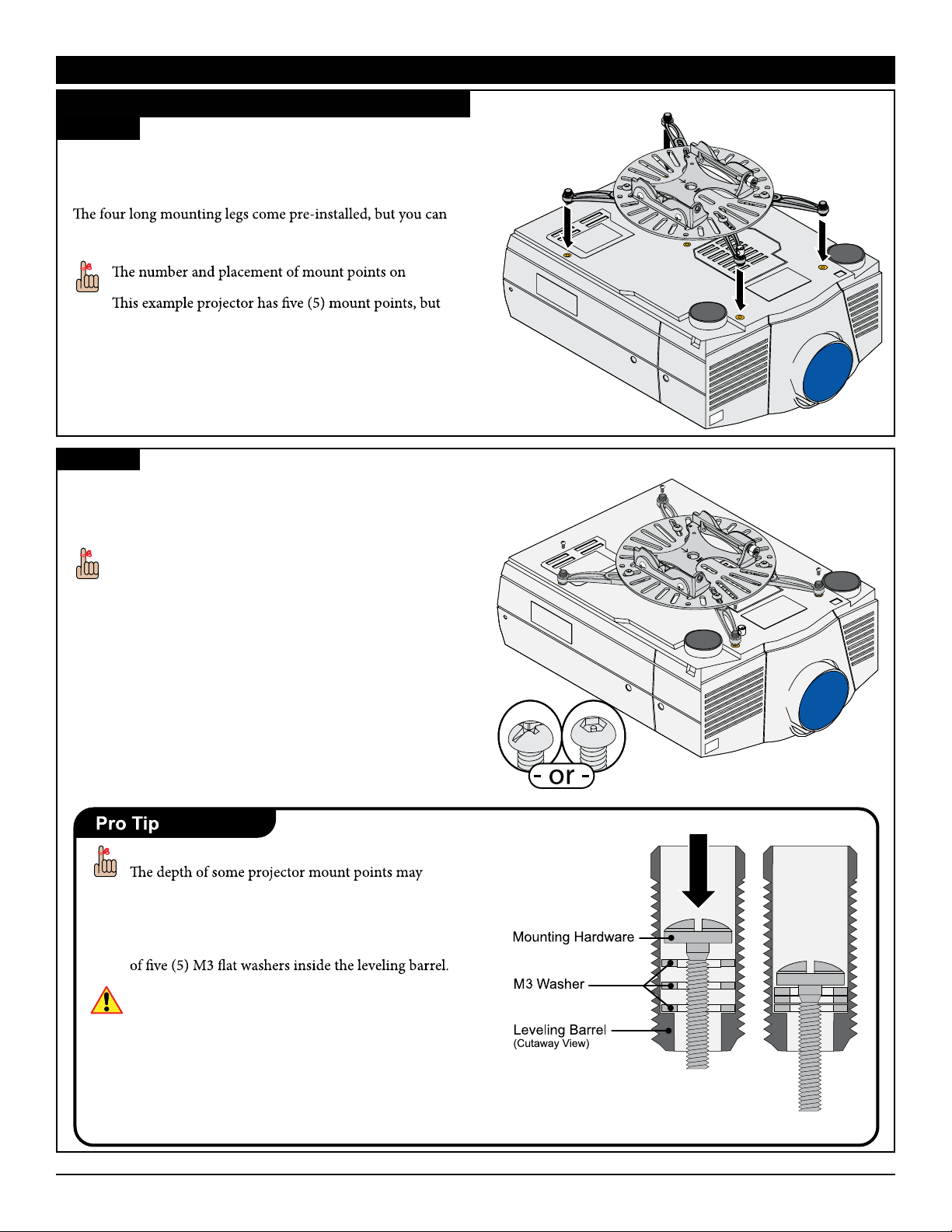
1) Locate the projector’s mount points.
2) Position an appropriate number of mounting legs on the
projector.
use three (3) or four (4) long and/or short mounting legs
depending on what your projector requires.
projectors varies between projector manufacturers.
only uses four (4) mounting legs.
Step 2
Insert the mounting hardware, as determined in the
“Selecting the Mounting Hardware” section, through
the leveling barrels of the mounting legs into the thread insert
of the projector.
Projector plate not
shown
You can use either the standard Phillips head or Lock-
It™ security hardware.
Do not tighten the mounting hardware at this time.
Mounting Hardware Too Long?
prevent you from tightening the M2.5 and M3
mounting hardware.
You can reduce the length of the M2.5 and M3
mounting hardware by stacking up to a maximum
Avoid stacking too many M3 washers; the mounting
hardware must thread into the projector mount
point at least four (4) complete turns.
Installation Instructions Page 11
premiermounts.com | p. 800.368.9700 | e. [email protected]
Page 12
Attaching the Universal Projector Plate (cont’d)
Step 3
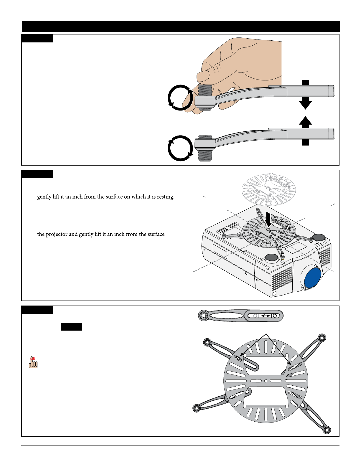
Raise or lower each of the mounting legs, by rotating the
leveling barrels, until all of the mounting legs are at an equal
height.
• Lower the mounting leg by rotating the leveling
barrel counter-clockwise.
• Raise the mounting legs by rotating the leveling
barrel clockwise.
Step 4
1) Identify the projector’s approximate front-to-back center of
gravity. Place your hands on each side of the projector and
Carefully adjust your grip on the projector until it seems
balanced from front-to-back. Mentally note the apparent
center of gravity.
2) Identify the projector’s approximate side-to-side center
of gravity. Place your hands on the front and back of
Side-to-Side
Center of Gravity
Fine Tune Projector Mount
Front-to-Back
Center of Gravity
on which it is resting. Carefully adjust your grip on
the projector until it seems balanced from side-to-side.
Mentally note the apparent center of gravity.
3) Place the Universal Projector Plate (if not already attached)
on top of the mounting legs with the center hole as close as
possible to the projector’s center of gravity.
Step 5
1) Verify that the mounting legs are at an equal height.
Return to Step 3 if they are not at an equal height or the
Universal Projector Plate is not level.
2) Verify the position of the integrated sliding M6 square
nut in the mounting leg relative to a nearby slot on the
Universal Projector Plate.
If the M6 square nut is not aligned with any slot, you can
use any thin implement, such as a toothpick, to nudge it
into alignment.
Sliding M6
Square Nut
Page 12 Installation Instructions
premiermounts.com | p. 800.368.9700 | e. [email protected]
Page 13
Fine Tune Projector Mount
Attaching the Universal Projector Plate (cont’d)
Step 6
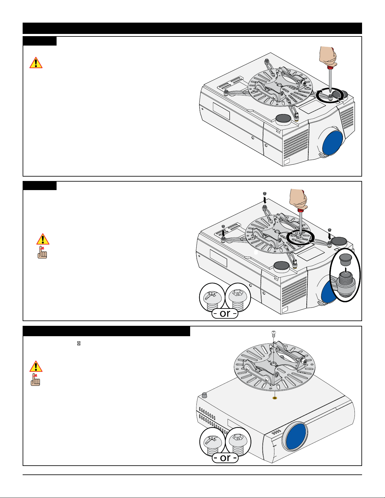
Tighten the mounting screws to the projector.
Do not overtighten the mounting screws.
Step 7
1) Attach the Universal Projector Plate (if not already
attached) to each of the mounting legs by inserting and
tightening one (1) M6 x 12mm screw through the Universal
Projector Plate into the M6 square nut on each of the
mounting legs.
Do not overtighten the mounting screws.
You can use either the standard Phillips head or
Lock-It™ security hardware.
2) Insert one (1) Barrel Cap into the end of each leveling barrel
(except the security leveling barrel).
Proceed to the “Securing the Quick Set Base” section.
Single Mount Point Installation
A single ¼-20 x
Projector Plate to the projector if your projector has only one
mounting point.
Do not overtighten the mounting screws.
You can use either the standard Phillips head or
Lock-It™ security hardware.
Proceed to the “Securing the Quick Set Base” section.
5
/16 screw must be used to attach the Universal
Installation Instructions Page 13
premiermounts.com | p. 800.368.9700 | e. [email protected]
Page 14
Fine Tune Projector Mount
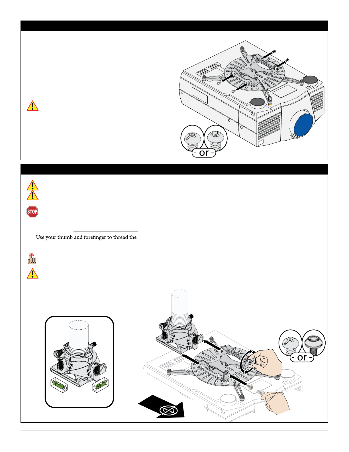
Securing the Quick Set Base
You had the option of installing Lock-It™ security hardware
during several of the previous steps. You may also exchange the
screws which secure the Universal Projector Plate to the Quick
Set Base.
1) Remove the four (4) Phillips head M6 x 8mm screws which
secure the Quick Set Base to the Universal Projector Plate.
2) Replace each M6 x 8mm Phillips head screw with one (1)
M6 x 8mm Security screw.
3) Tighten all screws.
Do not overtighten the mounting screws.
Proceed to the “Attaching the Projector to the Mount”
section.
Attaching the Projector to the Mount
If your projector is heavy and/or bulky, two people may be required to safely attach your projector to the FTP Dome.
If your projector is to be mounted higher than shoulder height, you may need to use one or more ladders to safely attach your
projector to the FTP Dome.
Verify that the FTP Dome is in the factory-default position prior to attempting to attach the Quick Set Base/projector
assembly. Serious damage to property or severe personal injury could occur if the FTP Dome is not at the factory-set position.
1) Raise the projector (with the Quick Set Base and Universal Projector Plate securely attached) and slide the Quick Set Base onto
the FTP Dome. Do not release the projector.
2)
3) Insert the M5 x 12mm screw into the location shown and tighten it using a Phillips screwdriver.
You can use either the standard Phillips head or Key Lock security hardware.
Do not overtighten the M5 x 12mm screw.
Proceed to the “Alignment & Fine-Tuning” section.
Captive Screw into the FTP Dome until it is hand-tight.
Captive
Screw
Page 14 Installation Instructions
premiermounts.com | p. 800.368.9700 | e. [email protected]
Page 15
Fine Tune Projector Mount
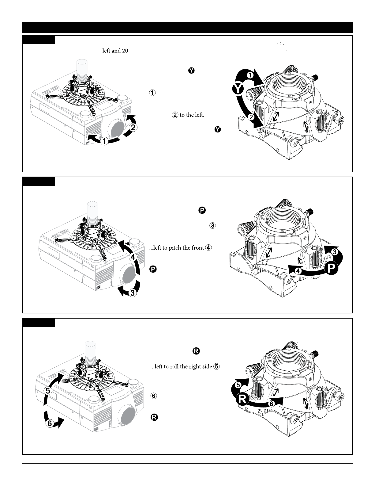
Alignment & Fine-Tuning
Yaw
Yaw can be adjusted up to 20° ° right from center.
Adjust the projector’s yaw by
turning control
...clockwise to pivot the front
to the right.
...counter-clockwise to pivot
the front
Each full revolution of the
control adjusts the yaw by 4°.
Pitch
Pitch can be adjusted 15° down and 5° up from level.
...
Adjust the projector’s pitch
by spinning control
...right to pitch the front
down.
Each full revolution of the
by 1°.
Roll
Roll can be adjusted up to 5˚ to either side from level.
Adjust the projector’s roll by
spinning control
up.
...
up.
control adjusts the pitch
...
...right to roll the right side
down.
Each full revolution of the
control adjusts the roll
by 1°.
Installation Instructions Page 15
premiermounts.com | p. 800.368.9700 | e. [email protected]
Page 16
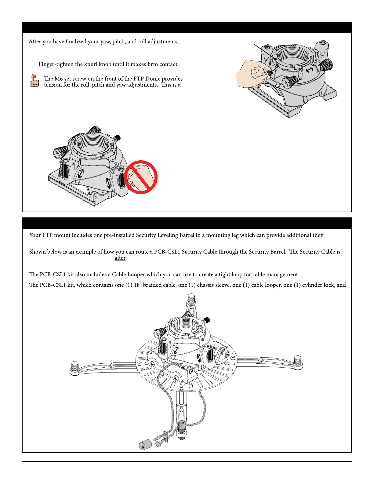
Locking in the Adjustments
Fine Tune Projector Mount
you can lock them in to prevent them from being accidentally
changed.
1)
with the FTP Support Sphere (Figure 1).
factory setting which you should not change (Figure 2).
Figure 2
FTP Support Sphere
Figure 1
Securing the Fine Tune Projector Mount
deterrence for your projector.
routed through the Security Barrel the standard leveling barrel is replaced by the Security Barrel and the projector mount is
securely attached to the projector as per the installation instructions.
two (2) cylinder lock keys, is sold separately. Additional cylinder locks, additional Security Barrels, and longer cables are also sold
separately.
Page 16 Installation Instructions
premiermounts.com | p. 800.368.9700 | e. [email protected]
Page 17
Fine Tune Projector Mount
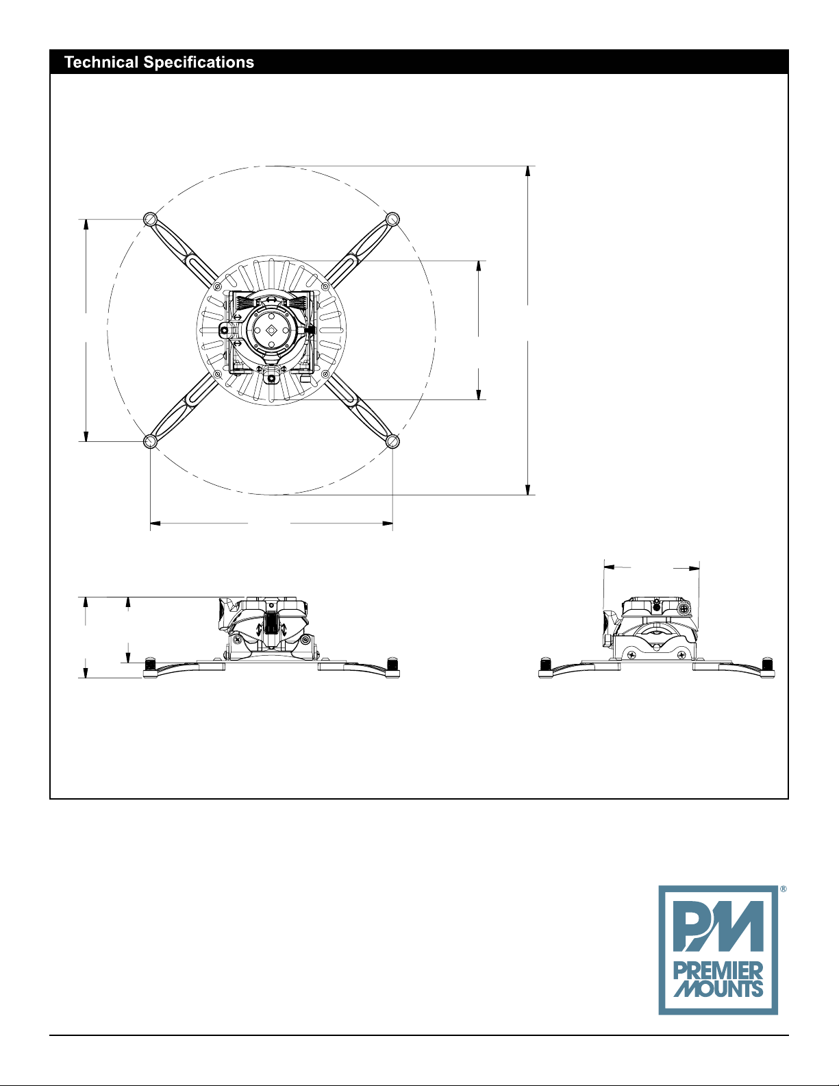
All measurements are in inches [mm].
11.09
[282]
4.05
[103]
ø 16.43
[417]
ø 6.94
[176]
12.12
[308]
4.76
[121]
3.28
[83]
PREMIER MOUNTS
©
500 W Central Ave, Suite A
Brea, CA 92821
USA & CANADA
Phone: 800-368-9700
Fax: 800-832-4888
Installation Instructions Page 17
premiermounts.com | p. 800.368.9700 | e. [email protected]
 Loading...