

Page 1
www.mounts.c om | Nor th America 800.368.970 0 | International +1-714-632-7100
1321 S. State Co llege Blvd., Fuller ton, CA 92831 USA
War ranty, Garantie, Garantía, Garanzia, Garantie, Waarborg: http://www.mounts.com/warranty
Installation Guide
Installationsanleitung, Guía de Instalacíon, Guida de Installazione, Guide d’Installation, Installatie gids
FPS-300
9535-000-011-0X Rev.2
Page 2

OPTIONAL POWER BOX
x8 x6 x4 x8
Included components
M8 x 16mm
M5 x 10mm M3 x 8mm 1/4” x 3”
x18
M4 x 5mm
x20
#8 x 1-1/4”
Note: Prior to installation start, the installer has the option
of concealed power and signal boxes mounted flush on
either the left or right side upper mounting rail end caps. If
power and signal cable are to be run externally to the end
cap, please note provisions have been made to allow for
external “wire mold” channel to be run into the end caps as
well.
Unpack all FPS-300 system components and confirm all
components called out in the supplied par ts list are accounted for. With all components laid out select the upper
mounting channel pieces as these will be the first part of the
system to install.
Note: If you are using the optional concealed left or right
side power and signal box sections, install only one side of
the upper track guide along with the power signal box cover
that is opposite of where the power and signal is coming
from. Power and signal cables must run together from either
the left or right side for proper operation of the system.
x8
1/4”
Required for installation
7/16 ”
x20
#10
x2
1
OUTLET LOCATION
Mounting
Distance
Desired
Distance
x5
16.00 16.00
16.00
C
WALL STRUCTURE
FACTOR
15.250"
L
Display Width
x1
1/8” / 3.25mm
(Wood Only)
THE FIRST SLOTS MUST
ALWAYS HAVE AN ANCHOR
ON EITHER END IN ANY GIVEN
INSTALLATIONAPPLICATION
OPTIONAL POWER BOX
OUTLET LOCATION
53.38
(HOLD DIM)
ROLLER PLATE
Mounting Distance = Display Width/2 + Desired Distance - 15.25”
Page 3
Warranty: http://www.mounts.com/warranty
Garantie, Garantía, Garanzia, Garantie, Waarborg
Updates: The most up-to-date installation
guides can be found at mounts.c om
www.mounts.c om | Nor th America 800.368.970 0 | International +1-714-632-7100
2
Installation Guide
Installationsanleitung, Guía de Instalacíon, Guida de Installazione, Guide d’Installation, Installatie gids
FPS-300
A
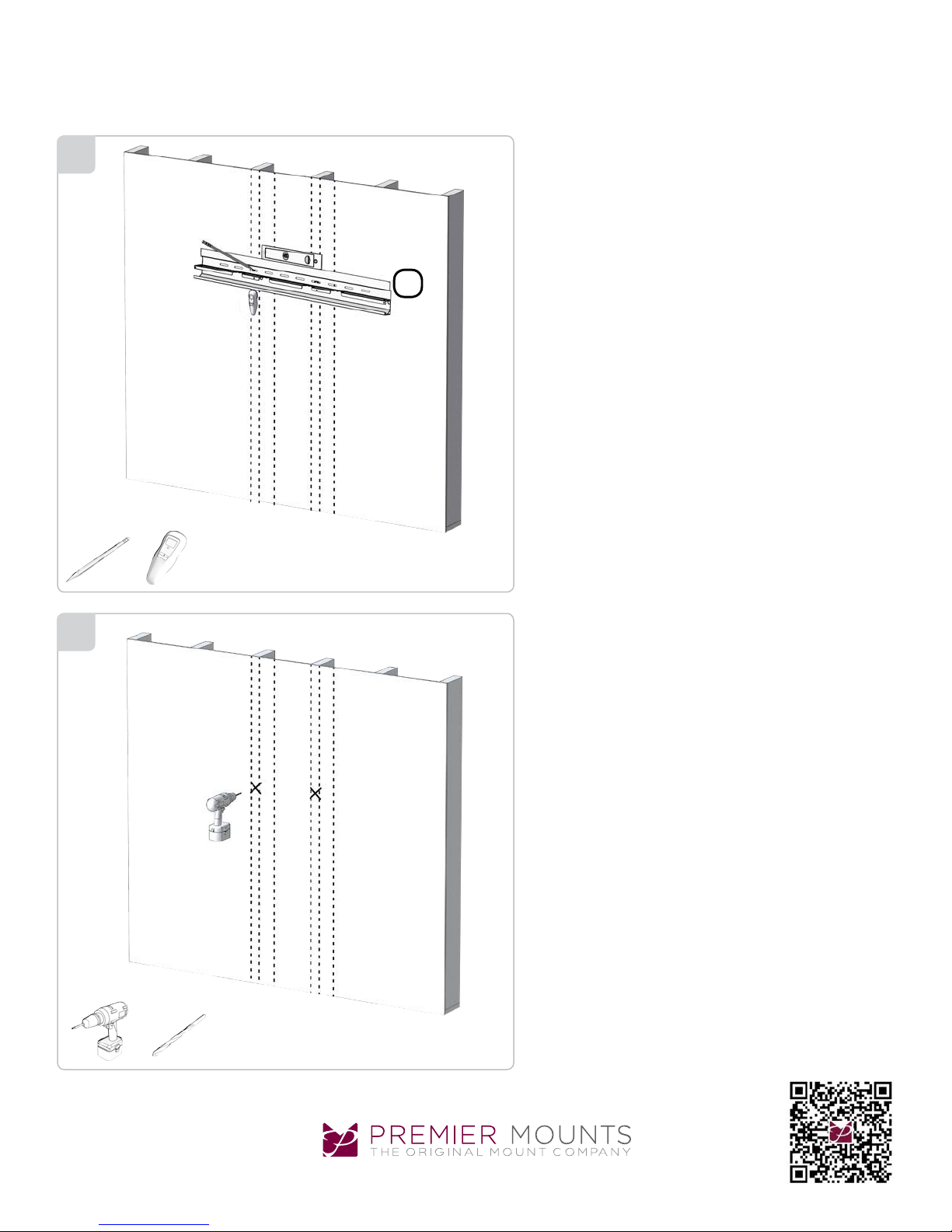
Take one 48 in. upper channel section (A) and place it
horizontally on the wall and level at the desired height, in
line with both the predetermined stud locations and with
anchoring position in the far right or left slot. Mark through
the upper channel mounting holes directly on the wall.
Note: Be sure you have clear space behind the dry wall if
you are using the concealed mounting power and signal box
option. For concrete or other solid wall construction, follow
the same process as above, but using suitable hardware for
best installation requirements.
3
Depending on the composition of the installation wall, drill
the pilot holes with the proper size drill bit to a depth allowing for full penetration of the mounting screw in the wall to
provide a level and firmly attached upper mounting channel.
9535-000-011-0X Rev.2
Page 4

Once the mounting pilot holes have been drilled, take the
first 48 in. (1219mm) section of mounting channel and secure it level on the wall with the mounting hardware provided. Once the first upper channel is secure, follow the same
procedure for the second 48 in. (1219mm) upper channel.
Do not overtighten the screws.
A: Make sure the two upper channel sections are locked to-
gether inside the locking tabs provided at the channel ends.
Do NOT tap on the small protruding tabs.
4
A
Once the center height is confirmed at 53.38” between the
upper and lower channels, mark and drill pilot holes for the
#10 plastic anchor. Follow the same procedure as step 4
above to install the lower two mounting channel sections,
ensuring the interlocking tabs are together.
Note: Be sure the upper and lower channels are level with
each other and in line at the same starting point as called
out in the instructions.
5
7/16 ”
1/4” x 3”
1/4”
#8 x 1-1/4”#10
Page 5

FPS-300
Installation Guide
Installationsanleitung, Guía de Instalacíon, Guida de Installazione, Guide d’Installation, Installatie gids
With both upper and lower channels level and secure to the
6
wall, the main slider assembly can be raised (two people
recommended) with the upper rollers properly seated into
the upper channel receiver slots. Once fully seated, the lower rollers should be on center with the lower roller channel.
7
Install the power signal boxes to each end.
Complete all electrical installation at this time.
Note: The upper slider assembly can also be wired using
appropriate wire connection.
Warranty: http://www.mounts.com/warranty
Garantie, Garantía, Garanzia, Garantie, Waarborg
9535-000-011-0X Rev.2
www.mounts.c om | Nor th America 800.368.970 0 | International +1-714-632-7100
Updates: The most up-to-date installation
guides can be found at mounts.c om
Page 6
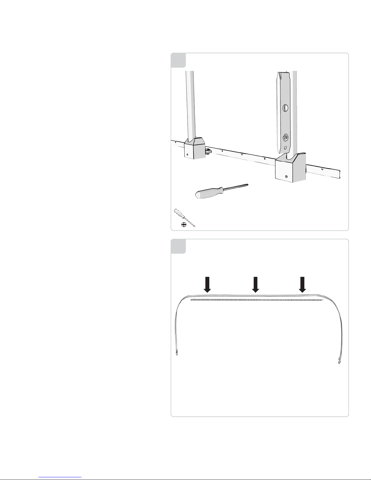
Using the spirit level supplied, adjust the stand off of the
lower roller wheels to provide a level vertical for the slider
frame on the wall. Loosen the locking screw at the bottom of
the roller using a Phillips head screwdriver. Install the dome
plug and tighten the bottom lock screw once the slider is
level.
8
Use UL or VDE listed flexible electrical cord appropriate
for this installation. (Contact your local electrician for more
information).
Push the cord into the plastic guide track, leaving sufficient
length open on either end for full motion of the display on
the slider. Hard wire the cords to universal electrical box.
Repeat for signal cable installation.
9
Page 7
FPS-300
Installation Guide
Installationsanleitung, Guía de Instalacíon, Guida de Installazione, Guide d’Installation, Installatie gids
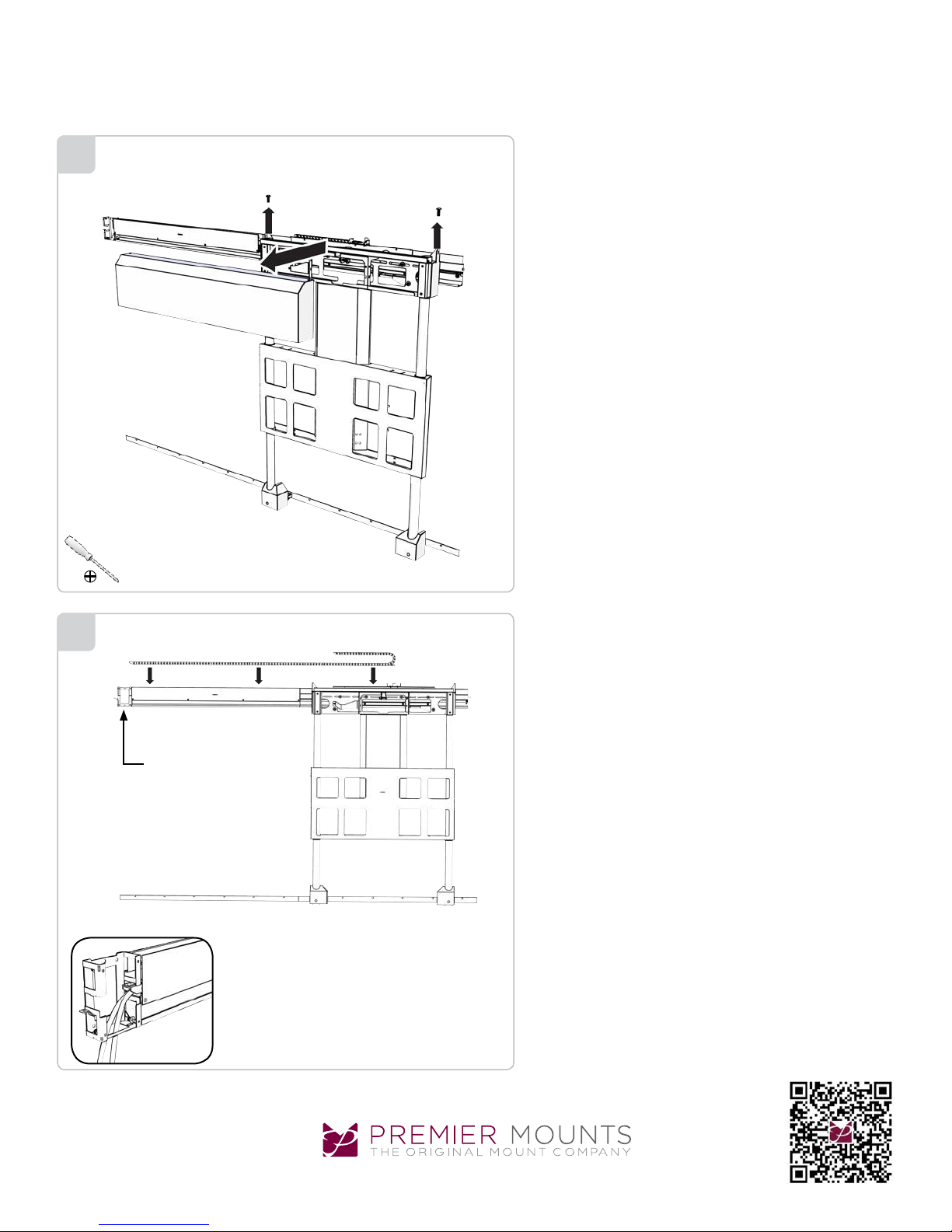
Remove the top cover on the slider assembly and set aside
10
for later re-install.
11
Power
Lay the plastic track glide unit with power and signal cable
installed within track section fully inside the upper channel
receiver section. Dress out the power and signal cable at
each end using the tie wraps supplied to insure smooth full
travel of the slider assembly in both the vertical and horizontal movements of the system.
Note: The orientation of the track will be determined by
where the power box was installed.
Warranty: http://www.mounts.com/warranty
Garantie, Garantía, Garanzia, Garantie, Waarborg
9535-000-011-0X Rev.2
www.mounts.c om | Nor th America 800.368.970 0 | International +1-714-632-7100
Updates: The most up-to-date installation
guides can be found at mounts.c om
Page 8
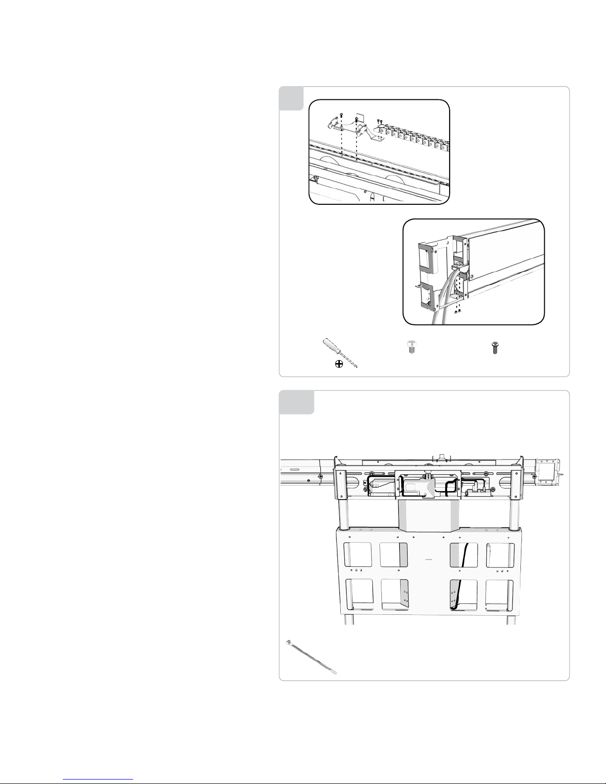
Secure both ends of the cable track system to the upper
channel structure with the track brackets and hardware supplied as shown in the visual diagram.
Secure the power strip to the frame using two (2) M3x8mm
screws and two (2) M3 kep nuts.
12
Double check all power and signal cables are properly secured to the system channels as to not cause any pinching
of the cables during any movement of the slider system.
13A
x2
M5 x 10mm
x4
M3 x 8mm
Page 9
FPS-300
Installation Guide
Installationsanleitung, Guía de Instalacíon, Guida de Installazione, Guide d’Installation, Installatie gids
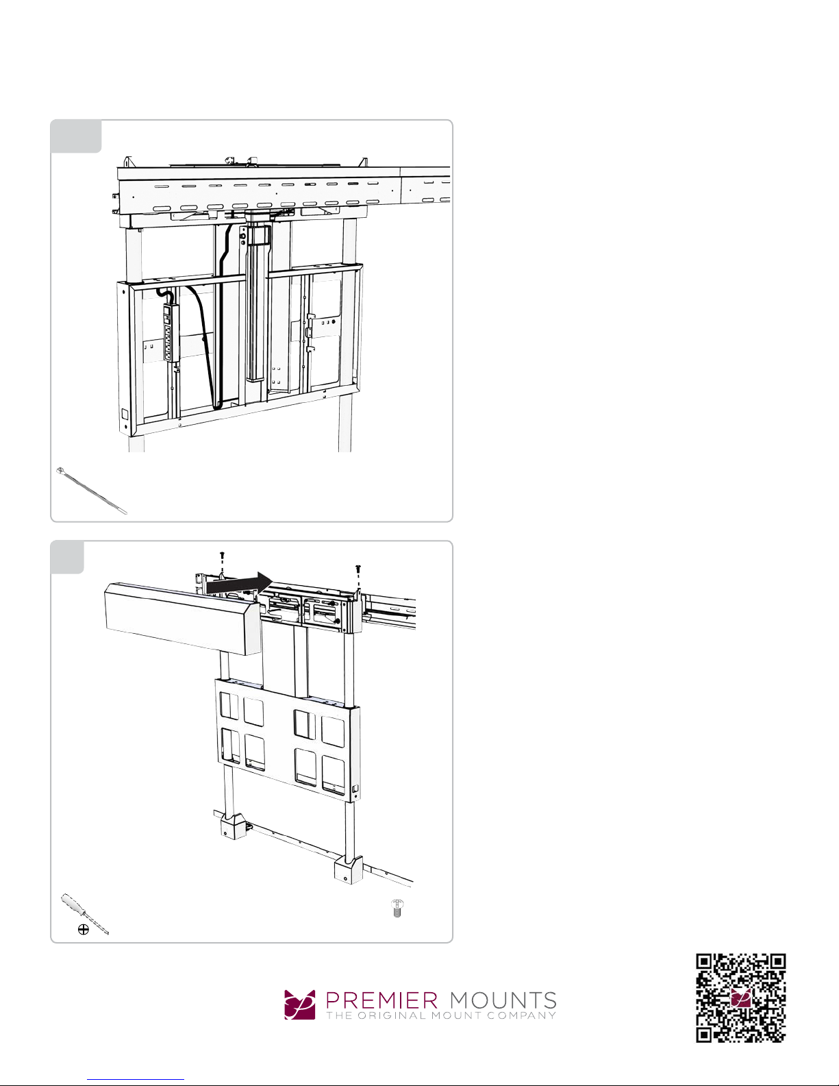
Use additional tie wraps as needed for proper wire and
13B
cable routing.
14
Re-install the upper channel and end covers securely at this
time.
x2
M5 x 10mm
Warranty: http://www.mounts.com/warranty
Garantie, Garantía, Garanzia, Garantie, Waarborg
9535-000-011-0X Rev.2
www.mounts.c om | Nor th America 800.368.970 0 | International +1-714-632-7100
Updates: The most up-to-date installation
guides can be found at mounts.c om
Page 10

Install the power signal box covers and channel covers.
15A
x8
M4 x 5mm
15B
x8
M4 x 5mm
Page 11
Warranty: http://www.mounts.com/warranty
Garantie, Garantía, Garanzia, Garantie, Waarborg
Updates: The most up-to-date installation
guides can be found at mounts.c om
www.mounts.c om | Nor th America 800.368.970 0 | International +1-714-632-7100
16
Installation Guide
Installationsanleitung, Guía de Instalacíon, Guida de Installazione, Guide d’Installation, Installatie gids
FPS-300
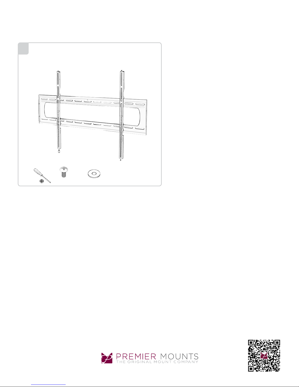
Refer to the “Universal Low Profile Flat Mount for 50″ to 80″
Flat Panels” for instruction on installing the display.
x8
M8 x 16mm 1/4”
x8
9531-060-001-00 Rev.2
Page 12

Warranty: http://www.mounts.com/warranty
Garantie, Garantía, Garanzia, Garantie, Waarborg
www.mounts.c om | Nor th America 800.368.970 0 | International +1-714-632-7100
Updates: The most up-to-date installation
guides can be found at mounts.c om
Installation Guide
Installationsanleitung, Guía de Instalacíon, Guida de Installazione, Guide d’Installation, Installatie gids
FPS-300
Premier Mounts intends to make this manual accurate and complete. However, Premier Mounts makes no claim that
the information contained herein covers all details, conditions or variations, nor does it provide for every possible
contingency in connection with the installation or use of this product. The information contained in this document
is subject to change without notice or obligation of any kind. Premier Mounts makes no representation of warranty,
expressed or implied, regarding the information contained herein. Premier Mounts assumes no responsibility for
accuracy, completeness or sufciency of the information contained in this document.
PREMIER MOUNTS
LIMITED LIFETIME WARRANTY
What and Who is Covered by this Limited Lifetime Warranty
Premier Mounts warrants all mounting products to be free from defects in material and workmanship for
the lifetime of the original installation of the product.
What Premier Mounts Will Do
At the sole option of Premier Mounts, Premier Mounts will repair or replace any product or product part
that is defective. If Premier Mounts chooses to replace a defective product or part, a replacement product or part will be shipped to you at no charge, but you must pay any related labor costs.
What is Not Covered: Limitations
Premier Mounts disclaims any liability for damage to mounts, adapters, displays, projectors, other
property, or personal injury resulting, in whole or in part, from improper installation, modication, use or
misuse of its products.
NOTWITHSTANDING ANYTHING TO THE CONTRARY IN THIS WARRANTY, THIS WARRANTY IS
LIMITED TO FIVE YEARS FROM THE DATE OF PURCHASE IN THE EVENT THAT THE WARRANTED PRODUCT IS COMMERCIALLY RENTED OUT.
Electrical products and components, such as ampliers, speakers, motors, switches remote controls
and related electrical items, are backed by a 3-year warranty.
Premier Mounts disclaims all other warranties, express or implied, including warranties of merchantability and tness for a particular purpose. Premier Mounts is not responsible for incidental or consequential damages, including but not limited to, inability to use its products or labor costs for removing
and replacing defective products or parts. Some states do not allow the exclusion or limitation of incidental or consequential damages, so the above limitation or exclusion may not apply to you.
What Customers Must Do for Warranty Service
If you discover a problem that you think may be covered by the warranty, you must report it in writing to the address below within thirty (30) days. Proof of purchase (an original sales receipt) from the
original consumer purchaser must accompany all warranty claims. Warranty claims must also include
a description of the problem, the purchaser’s name, address, and telephone number. General inquiries
can be addressed to Premier Mounts Customer Service at 1-800-368-9700. Warranty claims will not be
accepted over the phone or by fax.
Premier Mounts
Attn: Warranty Claim
1321 S. State College Blvd.
Fullerton, CA 92831 USA
How State Law Applies
This warranty gives you specic legal rights, and you may also have other rights which vary from state
to state.
9535-000-011-0X Rev.2
 Loading...