

Page 1
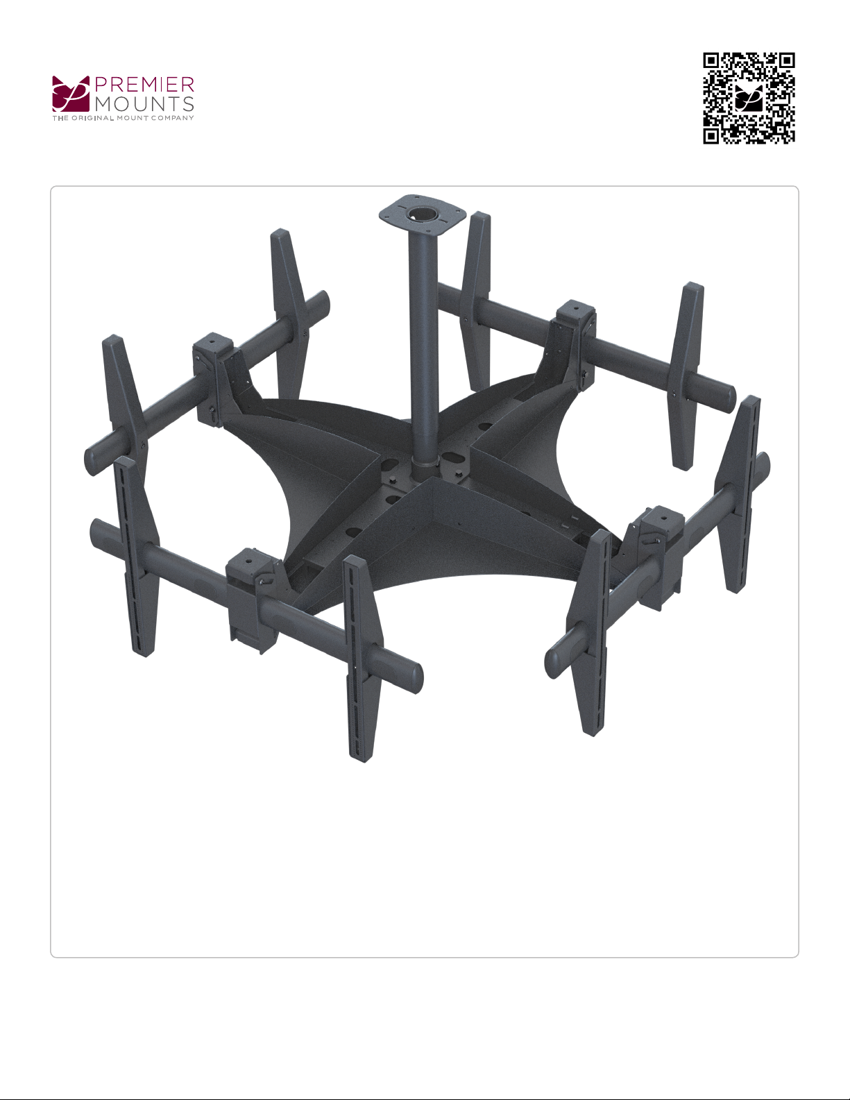
ECM-4000
Installation Guide
Installationsanleitung, Guía de Instalacíon, Guida de Installazione, Guide d’Installation, Installatie gids
Elliptical Ceiling Mount for 37˝ to 63˝ Flat Panels
Model: ECM-4000
War ranty, Garantie, Garantía, Garanzia, Garantie, Waarborg: http://www.mounts.com/warranty
www.mounts.c om | Nor th America 800.368.970 0 | International +1-714-632-7100
1321 S. State Co llege Blvd., Fuller ton, CA 92831 USA
9531-000-000-0X Rev.0
Page 2
Max Flat-Panel Capacity: 80 lb. each
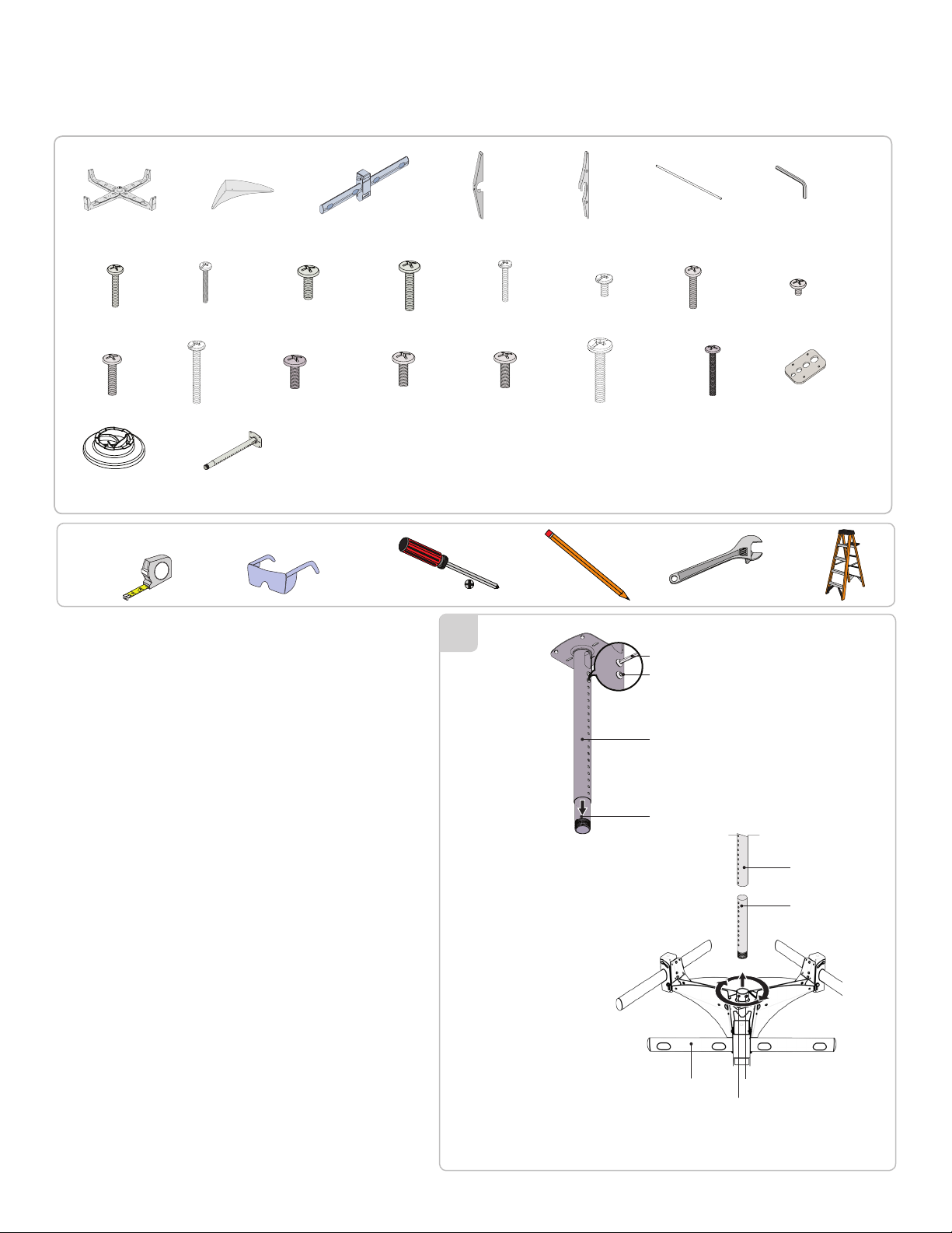
Included components
x1 x1 x4 x8 x8
Quad Mount
Structure
x24
M4 x 25mm
x24
M6 x 30mm
x98
Universal Spacers
side Skirt
x24 x24 x24
M4 x 30mm
x24
M6 x 45mm
M5 x 16mm
x24
M8 x 16mm
x1
AST-2446/2
Elliptical
Tilt Mount
x24
Required for installation
The ceiling should be capable of supporting a weight of at least ve times
the product weight. If not, the ceiling surface must be reinforced. Proper
installation procedure by qualied personnel as outlined in the installation
instructions must be adhered to.
Mounting hardware is not included with this product. Commercially
available hardware must be used for this installation. The hardware used
will depend on your installation environment (i.e. wood stud, concrete
surface, metal I-beam etc).
x24
M5 x 25mm
x24
M8 x 25mm
1
AST-2446/2
Decorative
Covers
M5 x 30mm
x24
M8 x 30mm
Mounting
Bracket Arms
M6 x 16mm
x24
M8 x 45mm
Thread Depth
Indicator
x24
M6 x 25mm
M8 x 70mm
Allen Wrench
M8 Pan
Philips
Screw
Upper Half
x4 x1
5
˝ Allen Wrench
32
x24
M4 x 16mm
x24
x32
Griplate™
Washers
Separate the upper and lower halves of the AST-2446/2 by removing both
M8 screws and wave washers. Unpack the trio mount and place it on the
ground.
The set screw on the threaded coupler must be backed out in order for the
AST-2446/2 to be threaded into place.
Thread the lower half of the AST-2446/2 into the threaded coupler on the
trio mount. The lower half of the AST-2446/2 must be threaded fully until
the piece is safely secured to the threads, then tighten the screw back into
place. Use the screwdriver to tighten the set screw once the AST-2446/2
has been attached.
The following steps must be performed by a minimum of three people:
Two people lift the trio mount into place. Align the upper and lower halves
of the AST-2446/2. Slide the lower half/trio mount into the upper half of the
AST-2446/2.
It is recommended that the height, and location, of the ECM-3000 be
determined prior to performing the following steps.
Determine the mounting height. Align the M8 mounting holes on the upper
and lower halves of the AST-2446/2 and insert the M8 screws and wave
washers. Use the 516˝ wrench to tighten the M8 screws.
Verify that all hardware is secure and tight before proceeding to the next
section.
Minimum four (4)
complete turns
Lower Half
Mount
Pan Philips
Threaded
Coupler
Upper Half
Lower Half
Page 3
ECM-4000
Installation Guide
Installationsanleitung, Guía de Instalacíon, Guida de Installazione, Guide d’Installation, Installatie gids
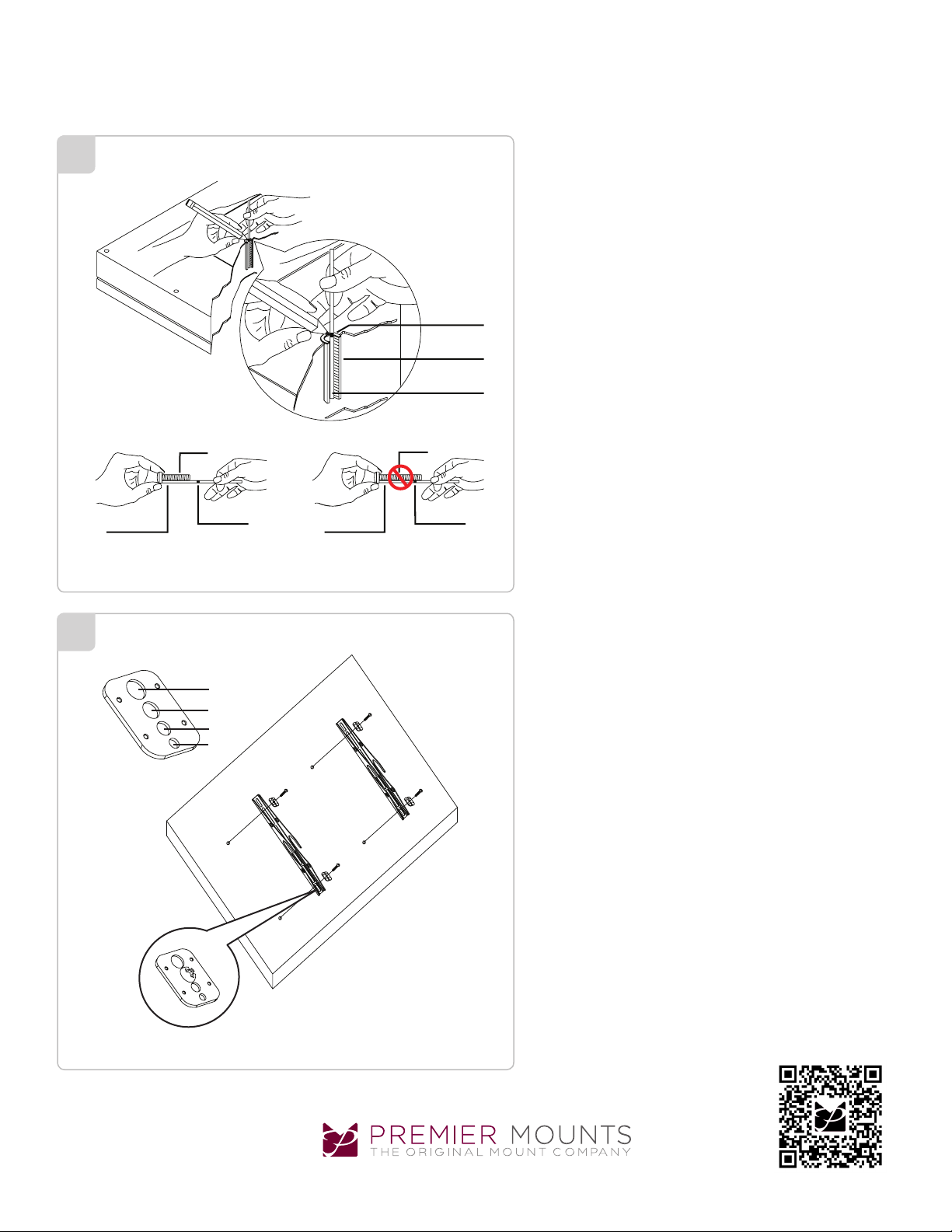
Insert the Thread Depth Indicator into the thread inserts
2
Inverted
Projector
Marking the
Depth
Threaded
Insert
Thread Depth
Indicator
found on the bottom or top of the projector. Use a pencil to
mark the depth of the thread insert on the Thread Depth Indicator, as shown. Insert the Thread Depth Indicator into the
remaining thread inserts to compare and verify their depth.
Locate the correct diameter screw for the thread insert.
If the screw you selected is longer than the mark on the
Thread Depth Indicator, as shown in Figure 2 and Figure 3,
do not use this screw. The screw length must not bypass
the mark.
Select another screw length until you find a screw that
comes closest to the mark without going past the mark.
Test each size of the screws provided.
3
Thread Depth
Indicator
Figure 2
M8
M6
M5
M4
Figure 1
Thread Depth
Indicator
ScrewScrew
Figure 3
The correct screws should thread easily into the mount point
and not pull out when tension is applied.
The optional M3 flat washers may be used to decrease the
screw depth of either the M2.5 x 12mm screws or the M3 x
16mm screws. Decrease the screw depth by placing an M3
Depth MarkDepth Mark
flat washer inside the leveling barrel and then inserting the
mounting screw.
Premier Mounts’ Griplate™ Washers are designed to accommodate the various M4, M5, M6 and M8 hole sizes required
by flat panels.
Do not place excessive pressure on the back of the flat
panel, as this may damage your flat panel.
The Griplate™ Washer must be installed between the head
of the mounting screw and the mounting bracket as shown.
Does your flat panel have:
Recessed mount points?
Uneven mount points?
A curved back?
Any obstruction near the mount point?
Warranty: http://www.mounts.com/warranty
Garantie, Garantía, Garanzia, Garantie, Waarborg
9531-000-000-0X Rev. 0
www.mounts.c om | Nor th America 800.368.970 0 | International +1-714-632-7100 | Europe +44 (0) 24 7664 4105
If Yes, you must install nylon spacers. Remove the mounting brackets, Griplate™ washers, and mounting screws from
the back of the flat panel.
Updates: The most up-to-date installation
guides can be found at mounts.c om
Page 4
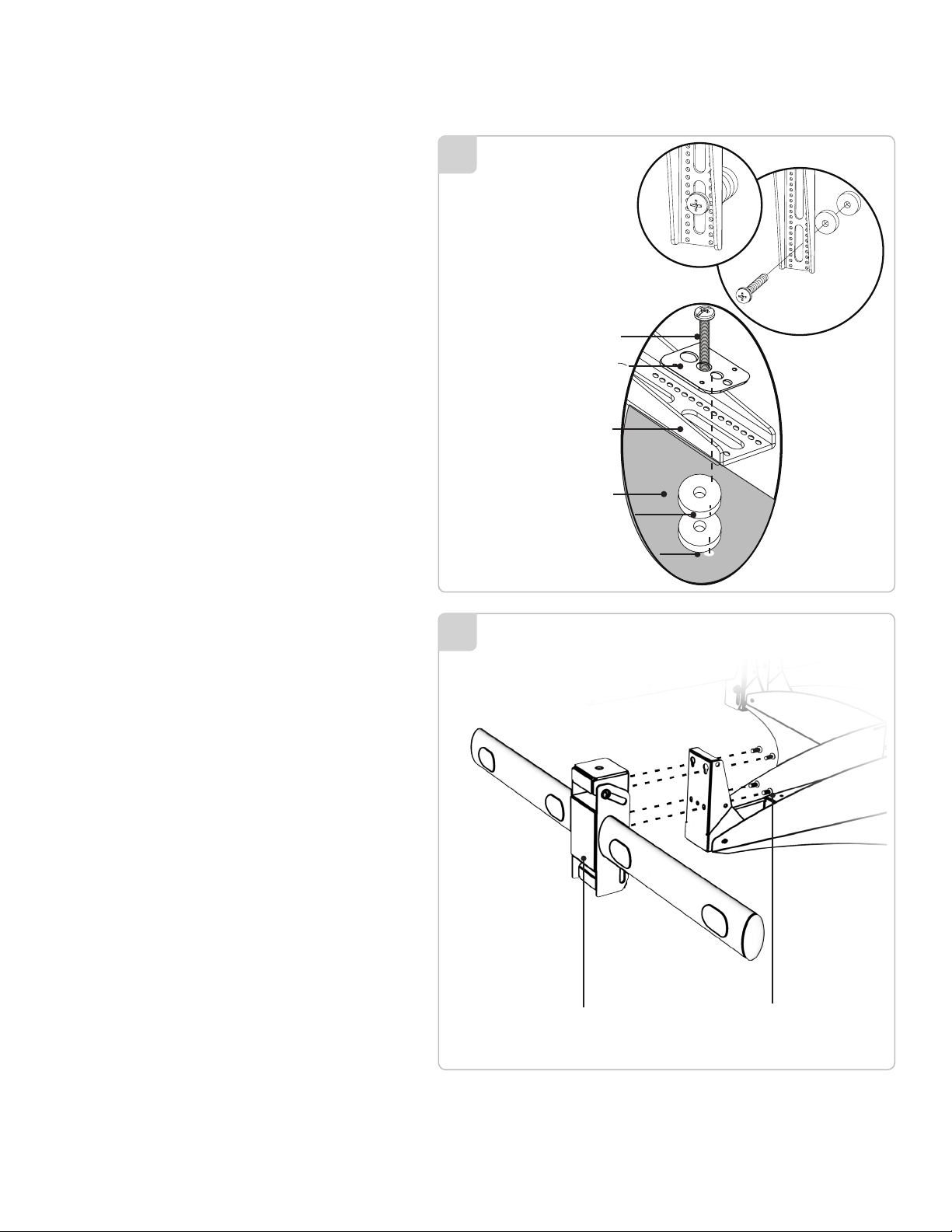
Premier Mounts’ nylon spacers allow you to attach the mounting
bracket to at panels which have recessed or uneven mount points.
Each nylon spacer will add distance between the mounting bracket
and your at panel.
The nylon spacers must only be installed between the mounting
bracket and your at panel.
The nylon spacers will t M4, M5, M6 and M8 screw sizes.
4
Mounting Screw
Griplate™ Washer
Mounting Bracket
Flat Panel
Nylon Spacer
Mount Point
Attach the eliptical tilt mount using four(4) M6 x 6mmscrews
5
Eliptical Tilt Mount
M6 x 6mm screw
Page 5
ECM-4000
Installation Guide
Installationsanleitung, Guía de Instalacíon, Guida de Installazione, Guide d’Installation, Installatie gids
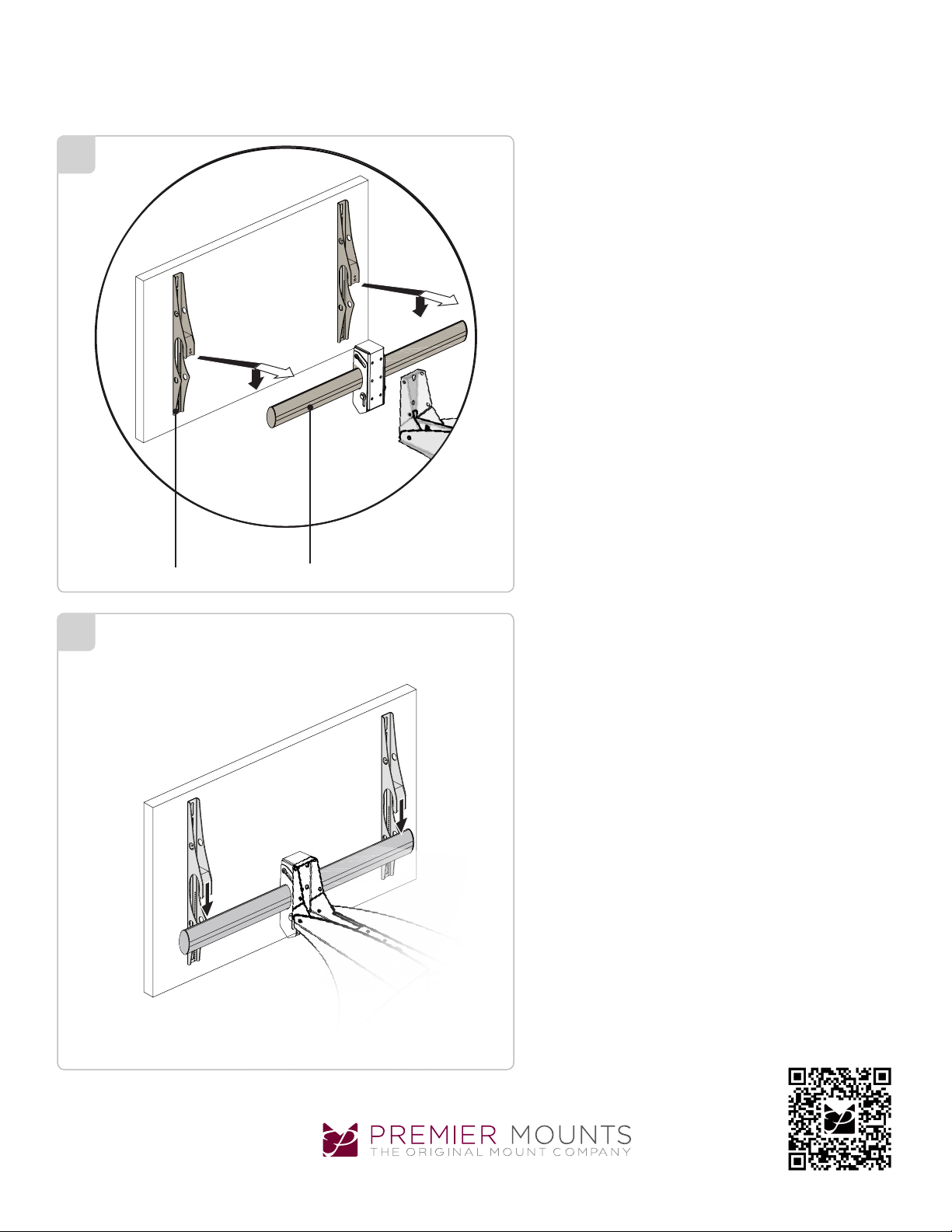
Install the mount according to the instructions provided by
6
Premier Mounts. Ensure all structural reinforcements have
been made before attaching the flat panel to the ECM- 4000.
Do not release the flat panel until the mounting bracket arms
are fully resting on the elliptical mounting bar.
Raise the mounting bracket arms and the attached flat panel
over the elliptical mounting bar of the ECM-4000.
7
Mounting Bracket Arms Elliptical Mounting Bar
Lower and center the mounting bracket arms with the attached flat panel onto the elliptical mounting bar of the
ECM-4000.
Repeat Steps 1 and 2 for mounting the remaining elliptical
tilt mounts.
Do not release the flat panel until the mounting bracket arms
are resting fully on the elliptical mounting bar.
Warranty: http://www.mounts.com/warranty
Garantie, Garantía, Garanzia, Garantie, Waarborg
9531-000-000-0X Rev. 0
www.mounts.c om | Nor th America 800.368.970 0 | International +1-714-632-7100 | Europe +44 (0) 24 7664 4105
Updates: The most up-to-date installation
guides can be found at mounts.c om
Page 6
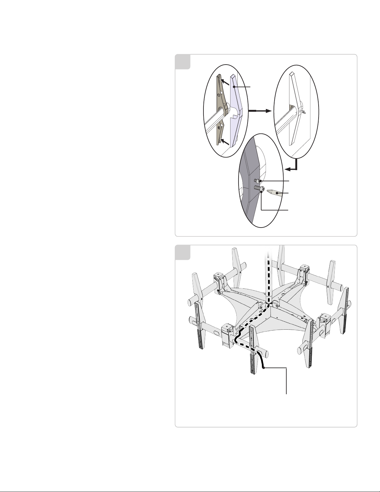
When attaching the decorative covers, verify that the
smaller mounting hole is above the larger mounting hole.
8
Place the first decorative cover over the first mounting
bracket arm and push f irmly into place.
Align the mounting holes together.
Insert the M4 x 6mm Phillips screw (smaller mounting
hole).
Insert the M6 x 25mm Phillips screw (larger mounting
hole).
Use a screwdriver to tighten all decorative cover
mounting hardware.
Repeat Steps 1 through 5 for the remaining decorative
covers and mounting bracket arms.
Do not over tighten these screws
Route the cables through the cable access holes and to their
respective locations. Remove the plastic covers, route the cables, and
gently re-attach the plastic covers.
Decorative
Cover
M4 x 6mm Screw
Screwdriver
M6 x 25mm Screw
9
The cables may then be routed through the bracket, up the ceiling
adapter and into the ceiling to a predetermined power source.
Source or
A/V Cable
Page 7
ECM-4000
Installation Guide
Installationsanleitung, Guía de Instalacíon, Guida de Installazione, Guide d’Installation, Installatie gids
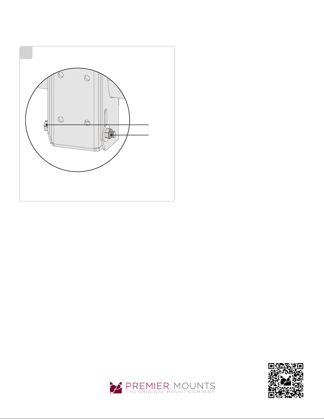
Adjusting the Flat Panel Friction Tilt Angle
10
Place one hand at the center top edge of the flat panel.
Place the other hand on the center bottom edge of the
flat panel.
Using the upper hand, gently pull the top of the flat panel
towards you while the lower hand gently pushes the
bottom of the flat panel away from you.
If additional tilt friction is required, tighten the lower nut
and lower bolt only to increase the tilt friction.
Lower Bolt
Lower Nut
Adjusting the Flat Panel to the Original Position
Place one hand at the center top edge of the flat panel.
Place the other hand on the center bottom edge of the
flat panel.
Using the upper hand, gently push the top of the flat
panel towards the wall while the lower hand gently pulls
the bottom of the flat panel away from the wall.
Warranty: http://www.mounts.com/warranty
Garantie, Garantía, Garanzia, Garantie, Waarborg
9531-000-000-0X Rev. 0
www.mounts.c om | Nor th America 800.368.970 0 | International +1-714-632-7100 | Europe +44 (0) 24 7664 4105
Updates: The most up-to-date installation
guides can be found at mounts.c om
Page 8

ECM-4000
Installation Guide
Installationsanleitung, Guía de Instalacíon, Guida de Installazione, Guide d’Installation, Installatie gids
PREMIER MOUNTS
LIMITED LIFETIME WARRANTY
What and Who is Covered by this Limited Lifetime Warranty
Premier Mounts warrants all mounting products to be free from defects in material and workmanship for the lifetime of
the original installation of the product.
What Premier Mounts Will Do
At the sole option of Premier Mounts, Premier Mounts will repair or replace any product or product part that is defective.
If Premier Mounts chooses to replace a defective product or part, a replacement product or part will be shipped to you
at no charge, but you must pay any related labor costs.
What is Not Covered: Limitations
Premier Mounts disclaims any liability for damage to mounts, adapters, displays, projectors, other property, or personal
injury resulting, in whole or in part, from improper installation, modication, use or misuse of its products.
NOTWITHSTANDING ANYTHING TO THE CONTRARY IN THIS WARRANTY, THIS WARRANTY IS LIMITED TO FIVE
YEARS FROM THE DATE OF PURCHASE IN THE EVENT THAT THE WARRANTED PRODUCT IS COMMERCIALLY
RENTED OUT.
Electrical products and components, such as ampliers, speakers, motors, switches remote controls and related
electrical items, are backed by a 3-year warranty.
Premier Mounts disclaims all other warranties, express or implied, including warranties of merchantability and tness
for a particular purpose. Premier Mounts is not responsible for incidental or consequential damages, including but not
limited to, inability to use its products or labor costs for removing and replacing defective products or parts. Some states
do not allow the exclusion or limitation of incidental or consequential damages, so the above limitation or exclusion may
not apply to you.
What Customers Must Do for Warranty Service
If you discover a problem that you think may be covered by the warranty, you must report it in writing to the address
below within thirty (30) days. Proof of purchase (an original sales receipt) from the original consumer purchaser must
accompany all warranty claims. Warranty claims must also include a description of the problem, the purchaser’s name,
address, and telephone number. General inquiries can be addressed to Premier Mounts Customer Service at 1-800368-9700. Warranty claims will not be accepted over the phone or by fax.
Premier Mounts
Attn: Warranty Claim
1321 S. State College Blvd.
Fullerton, CA 92831 USA
How State Law Applies
This warranty gives you specic legal rights, and you may also have other rights which vary from state to state.
Premier Mounts intends to make this manual accurate and complete. However, Premier Mounts makes no claim that the information contained herein covers all details,
conditions or variations, nor does it provide for every possible contingency in connection with the installation or use of this product. The information contained in this
document is subject to change without notice or obligation of any kind. Premier Mounts makes no representation of warranty, expressed or implied, regarding the
information contained herein. Premier Mounts assumes no responsibility for accuracy, completeness or sufciency of the information contained in this document.
Warranty: http://www.mounts.com/warranty
Garantie, Garantía, Garanzia, Garantie, Waarborg
9531-000-000-0X Rev. 0
www.mounts.c om | Nor th America 800.368.970 0 | International +1-714-632-7100 | Europe +44 (0) 24 7664 4105
Updates: The most up-to-date installation
guides can be found at mounts.c om
 Loading...