

Page 1
INSTALLATION MANUAL
IN-CTMMS2.R2
CTM-MS2
Premier Mounts
3130 E. Miraloma Avenue
Anaheim, CA 92806
Phone: (800) 368-9700 Fax: (800) 832-4888
mounts@mounts.com
www.mounts.com
Page 2

PBL-110 Projector Mount
Page - 2 - Installation Manual
Page 3

CTM-MS2
Table of Contents
Warning Statements ........................................................................................................................................- 4 -
Parts List ...........................................................................................................................................................- 5 -
Installation Tools ..............................................................................................................................................- 5 -
Mounting Bracket Installation .......................................................................................................................- 9 -
CTM-MS2 Installation ..................................................................................................................................- 12 -
Installing the Flat Panel Display (CTM-MS2) ............................................................................................- 14 -
Technical Specifications ................................................................................................................................- 17 -
Warranty ........................................................................................................................................................- 18 -
Contact Premier Mounts ...............................................................................................................................- 18 -
Notes ................................................................................................................................................................- 19 -
Installation Manual Page - 3 -
Page 4
Warning Statements
WARNING:
WARNING:
WARNING:
THE WALL STRUCTURE MUST BE CAPABLE OF SUPPORTING 160 LBS. IF NOT, THE WALL
STRUCTURE MUST BE REINFORCED. PROPER INSTALLATION PROCEDURE BY A QUALIFIED
SERVICE TECHNICIAN, AS OUTLINED IN THE INSTALLATION INSTRUCTIONS, MUST BE
ADHERED TO. FAILURE TO DO SO COULD RESULT IN SERIOUS PERSONAL INJURY, OR EVEN
DEATH.
SAFETY MEASURES MUST BE PRACTICED AT ALL TIMES DURING THE INSTALLATION OF
THIS PRODUCT. USE PROPER SAFETY GEAR AND TOOLS FOR THE INSTALLATION
PROCEDURE TO PREVENT PERSONAL INJURY.
PRIOR TO THE INSTALLATION OF THIS PRODUCT, THE INSTALLATION INSTRUCTIONS
SHOULD BE READ AND COMPLETELY UNDERSTOOD. THE INSTALLATION INSTRUCTIONS
MUST BE READ TO PREVENT PERSONAL INJURY AND PROPERTY DAMAGE. KEEP THESE
INSTALLATION INSTRUCTIONS IN AN EASILY ACCESSIBLE LOCATION FOR FUTURE
REFERENCE.
Indicates that the power plug is to be
disconnected from the power outlet.
Safety precautions must be taken at all
Contact Premier Mounts with any
questions.
times.
Warning and Caution statements.
Do not install on a structure that is prone to vibration, movement or chance of impact. Failure to
do so could result in damage to the flat panel display and/or damage to the mounting surface.
Do not install near heater, fireplace, direct sunlight, air conditioning or any other source of direct
heat energy. Failure to do so may result in damage to the flat panel display and could increase the
risk of fire.
At least two qualified people should perform the installation procedure. Injury and/or damage can
result from dropping or mishandling the flat panel display.
CTM-MS2
Page - 4 - Installation Manual
Page 5
CTM-MS2
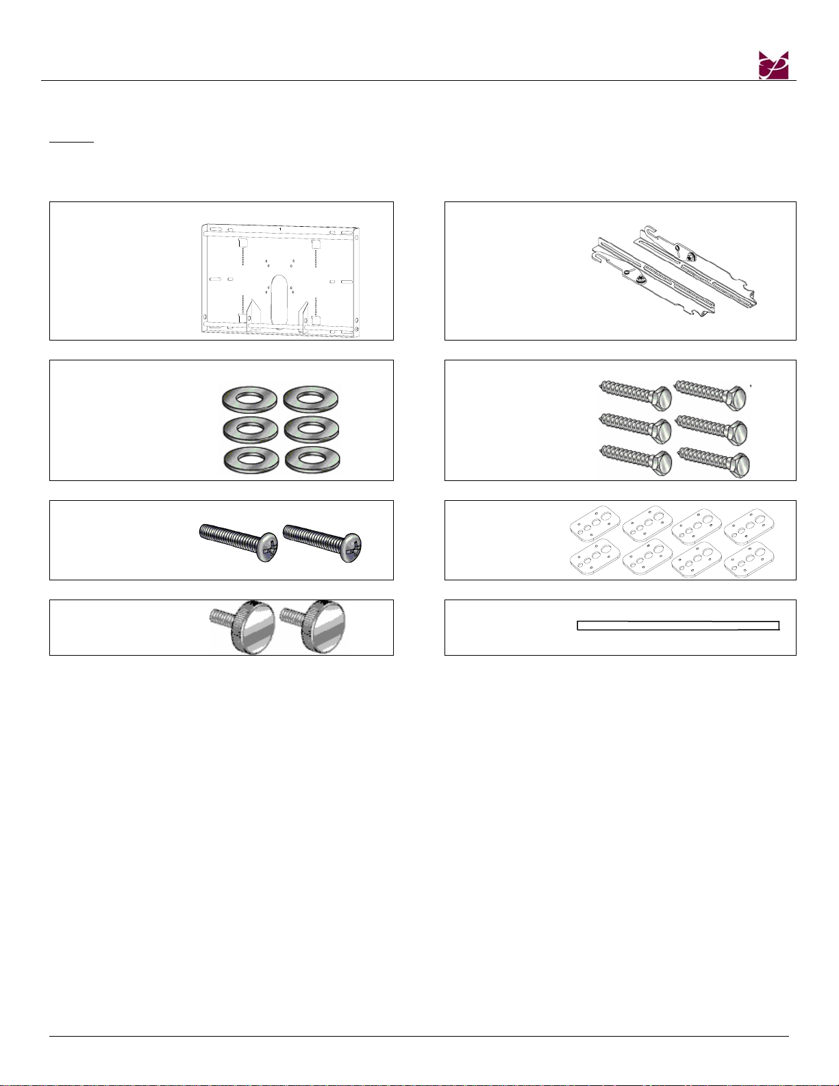
Parts List
NOTE: This wall mount is shipped with all proper installation hardware and components. Make sure that
none of these parts are missing and/or damaged before beginning installation. If there are parts
missing and/or damaged, please stop the installation and contact Premier Mounts
(800-368-9700).
WM4000 Wall
Plate (Qty 1)
Mounting
Brackets
(Qty 2)
5/16” Flat
Washers
(Qty 6)
5/16” x 3” Lag
Bolts (wooden
studs only) –
(Qty 6)
M6 x 30mm
Lateral Shift
Locking Screws
(Qty 2)
Griplates™
(Qty 8)
M6 x 12mm
Safety Knobs
(Qty 2)
Thread Depth
Indicator
Installation Tools
Phillips Head Screw Driver Soft Material/ Blanket 5/16” Socket and Wrench
Pencil Tape Measure Drill Gun
Level (Supplied)
Installation Manual Page - 5 -
Page 6
CTM-MS2
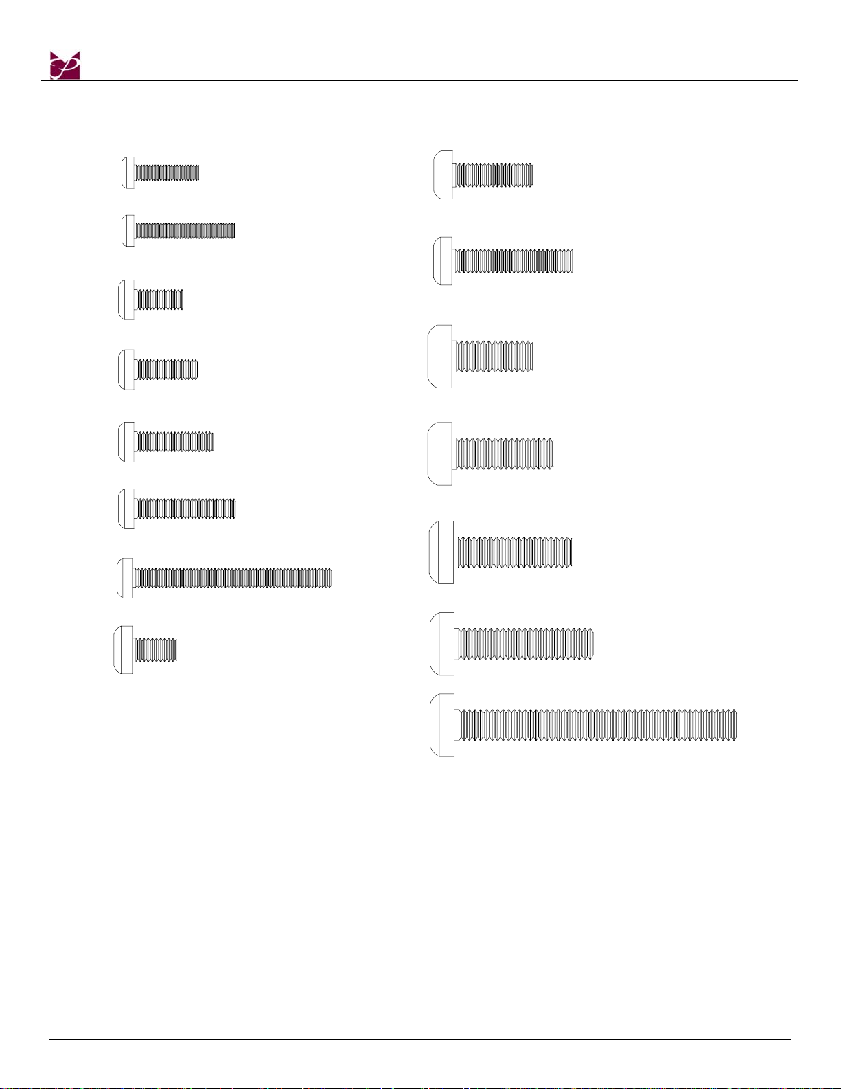
M4 x 16
M4 x 25
M5 x 12
M5 x 16
M5 x 20
M5 x 25
(Qty 8)
(Qty 8)
(Qty 6)
(Qty 4)
(Qty 6)
(Qty 4)
M6 x 20
M6 x 30
M8 x 20
M8 x 25
M8 x 30
(Qty 6)
(Qty 2)
(Qty 6)
(Qty 6)
(Qty 6)
M5 x 50
M6 x 12
(Qty 8)
(Qty 4)
M8 x 35
M8 x 70
(Qty 4)
(Qty 4)
Page - 6 - Installation Manual
Page 7
CTM-MS2
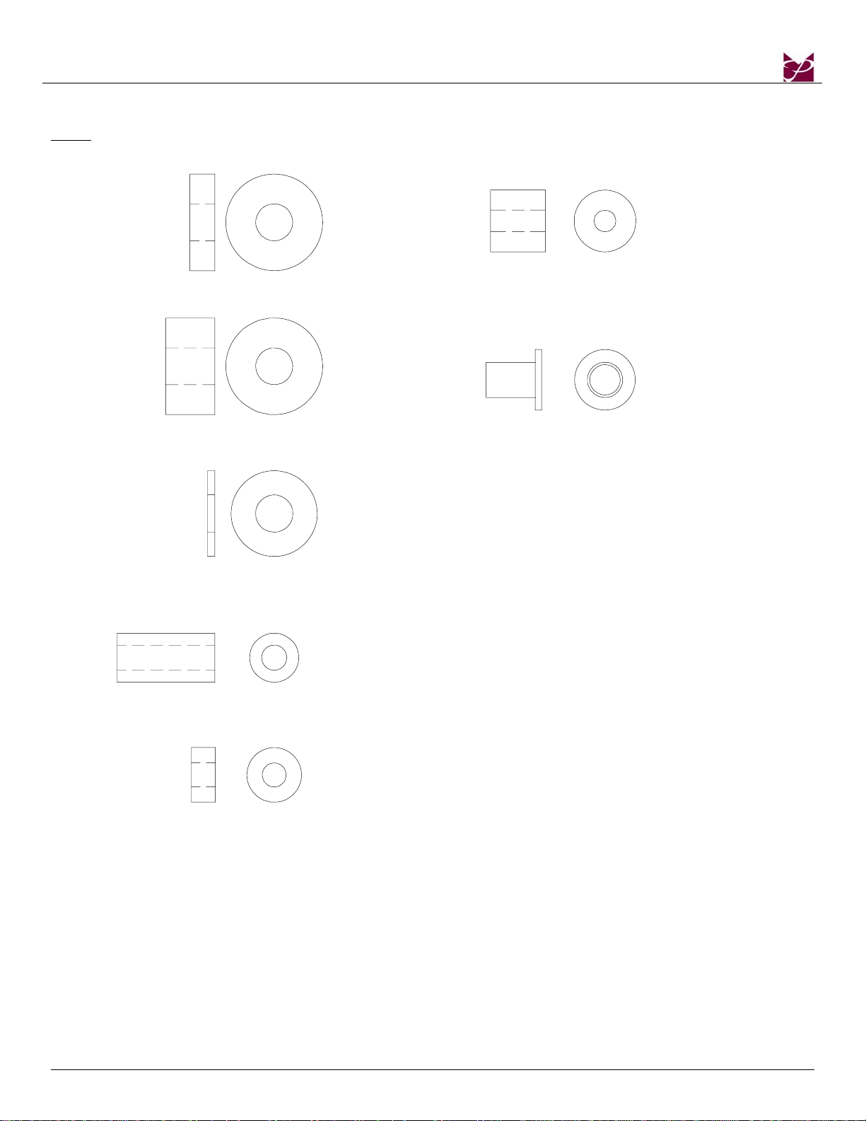
Nylon spacers and flat washers actual size
NOTE: The nylon spacers may be stacked to achieve proper spacing.
1/4" Nylo n space rs
(large)
(Qty 6)
1/2" Nylo n space rs
(large)
(Qty 12)
5/16" Flat washers
(metal)
(Qty 6)
9/16" Nylon spacers
(Qty 6)
Nylon sleeves
(Qty 4)
1" Nylon spacers
(Qty 6)
1/4" N ylon spacers
(small)
(Qty 6)
Installation Manual Page - 7 -
Page 8

CTM-MS2
Thread Depth Indicator
1. Insert the thread depth indicator (supplied) through the thread inserts found on the back of the flat
panel to make sure the inserts measure the same full depth and mark it (Figure 1).
2. Locate the correct diameter screw for the thread insert. Compare your marking to the screws (supplied).
3. If your selected screw is longer than the marking on the thread depth indicator, DO NOT USE this screw.
4. The screw length must not bypass the marking. Select another screw size (Figure 2 and 3), until you
find one that comes closest to your mark without going past.
Inverted flat panel
display
Marking the depth
Thread insert
Figure 1
Screw
Thread depth
indicator
Marking
Screw
Figure 2 Figure 3
Marking
Thread depth
indicator
Thread depth
indicator
Page - 8 - Installation Manual
Page 9

CTM-MS2
p
Mounting Bracket Installation
NOTE: Proper installation procedure by qualified personnel as outlined in the installation instructions must
be adhered to. Failure to do so could result in serious personal injury and possible damage to the
flat panel.
WARNING: INVERT THE FLAT PANEL PLACE IT ON A SOFT, FLAT SUFRACE TO PREVENT DAMAGE TO
THE FLAT PANEL. USE A BLANKET, FOAM, ETC. FAILURE TO DO SO WILL RESULT IN
DAMAGING THE FLAT PANEL. DO NOT LAY THE FLAT PANEL ON THE FLOOR WITHOUT ANY
PROTECTION TO THE GLASS. THE FLAT PANEL IS HEAVY AND FRAGILE. AT LEAST (2)
QUALIFIED PERSONNEL ARE STRONGLY RECOMMENDED FOR INSTALLATION OF THIS
PRODUCT. FAILURE TO DO SO COULD RESULT IN SERIOUS INJURY AND POSSIBLE DAMAGE
TO THE FLAT PANEL.
1. Once the flat panel is inverted, use a measuring tape to find the center of your flat panel measuring
from outside to outside of the chassis (Figure 4).
2. Using a pencil lightly mark the center of your flat panel (Figure 5).
Measuring tape
Inverted flat panelBottom of flat panel
Top of flat panel
C
L
Mark the center
of the flat
anel
Inverted flat panel
C
L
Figure 4 Figure 5
Installation Manual Page - 9 -
Page 10

3. Install the nylon spacers (if needed) to the mounting points on the flat panel (Figure 6).
4. Lay the left and right mounting brackets (stamped arrows facing out) - (Figure 7).
CTM-MS2
Center Mark
Nylon Spacers, If Applicable
Inverted Flat Panel
Arrows Facing Out
Mounting Brackets
Bottom of Flat Panel
Figure 6 Figure 7
5. Match the center of viewing guide with the centerline you marked in Step 1 (Figure 8).
6. The mounting brackets are designed with a center of viewing guide on the outside (Figure 9).
Page - 10 - Installation Manual
Page 11

CTM-MS2
F
P
P
P
p
Mounting Bracket
C
L
Bottom of Flat
anel
Center of
Viewing Guide
Align the Mounting
Brackets
Bottom of the
lat Panel
Center of Flat
anel
Figure 8 Figure 9
7. The Griplates™ have M4, M5 M6 and M8 hole patterns to fit the hardware that your flat panel requires.
EXAMPLE: If your plasma uses M8 x 20 Phillip screws. Use the M8 mounting points (Figure 10).
8. Once the mounting brackets are aligned secure the Griplate™ to the flat panel. Use (1) Griplate™ per
mounting point (Figure 11).
NOTE: The dimples of the top plates have to be facing up and the bottom dimples must be facing down.
Dimples Facing
U
Screw Driver
DIMPLES
FACING UP
DIMPLES
FACING UP
DIMPLES
FACING DOWN
Bottom of Flat
anel
M4 M5 M8 M6
DIMPLES
FACING DOWN
Figure 10 Figure 11
Installation Manual Page - 11 -
Page 12

W
y
w
CTM-MS2
CTM-MS2 Installation
1. Using a (commercially available) wood stud finder, locate the 16" or 24" stud centers behind the wall
(Figure 12).
2. Once found, make a pencil marking on the center of the wood studs (Figure 13).
NOTE: The wall plates have 16" and 24" mounting slot positions.
3. Place the wall plate to the reference line and mark the nine (9) lag bolt mounting points through the
wall plate slots on the wall.
Wood Stud Finder
(Commerciall
available)
16"
Mark the wall
and the center
of the wood
studs.
ood studs
behind the
wall
structure.
16"
Measure and
mark the
viewing height
desired on the
all.
Figure 12 Figure 13
NOTE: Although not depicted in the illustrations shown above, the width of this wall mount will encompass
four wall studs (three studs if 24” apart).
Page - 12 - Installation Manual
Page 13

CTM-MS2
4. Level the wall plate with the reference arrow pointing up to the ceiling (Figure 15).
5. Drill six (6) ¼" pilot holes to the marked wall.
6. Secure the plate using the six (6) 5/16" lag bolts and flat washers (Figure 16).
Mark the six (6) mounting
slot openings
16"
Wall Plate
Wall Plate
Figure 15
5/16” x 3” Lag
Bolts
Figure 16. Wood Installation
NOTE
: Although not depicted in the illustrations shown above, the width of this wall mount will
encompass four wall studs (three studs if 24” apart).
Installation Manual Page - 13 -
Page 14

CTM-MS2
Installing the Flat Panel Display (CTM-MS2)
WARNING: AT LEAST (2) QUALIFIED PERSONNEL ARE STRONGLY RECOMMENDED FOR INSTALLATION
OF THIS PRODUCT. FAILURE TO DO SO COULD RESULT IN SERIOUS INJURY AND POSSIBLE
DAMAGE TO THE FLAT PANEL.
1. Raise the flat panel with the LEFT and RIGHT mounting brackets secured to the flat panel and insert
the top hooks over the upper rod. The lower hooks should rest on the lower rod (Figure 17).
Wall Plate
Top
Bottom
Figure 17
NOTE: Although not depicted in the illustrations shown above, the width of this wall mount will
encompass four wall studs (three studs if 24” apart).
Page - 14 - Installation Manual
Page 15

CTM-MS2
W
L
2. Make any lateral shift adjustment and lock it by tightening the two (2) M6 x 30mm Phillips screws
found on the bottom of the mounting brackets. Use the foot leveler to adjust your plasma.
CAUTION: Do not over tighten the M6 x 30mm screws to the rods (Figure 18).
NOTE: To remove the display from the wall simply back off the M6 x 30mm screws using a Phillips
screwdriver and lift the unit of the wall carefully.
ateral Shift
all Plate
Figure 18
: Although not depicted in the illustrations shown above, the width of this wall mount will
NOTE
encompass four wall studs (three studs if 24” apart).
Installation Manual Page - 15 -
Page 16

CTM-MS2
3. Tilt the flat panel and secure the two (2) M6 x 12mm safety knobs to each of the mounting brackets
(Figure 19).
NOTE: To remove the display from the wall simply extend the display to its maximum tilt range, remove
the two 6 (mm) safety knurl knobs push the flat panel back to it’s flat position, loosen or remove
the two (2) M6 x 30 lateral shift screws and lift the unit of the wall.
Figure 19
NOTE: Although not depicted in the illustrations shown above, the width of this wall mount will
encompass four wall studs (three studs if 24” apart).
Page16 Installation Manual Page
Page 17

CTM-MS2
Technical Specifications
H
28.000
(171.2)
C
A
L
B
8.000
(203.2)
21.000
19.000
C
L
8.000
(203.2)
(482.6)
C
(533.4)
G
F
G
H
19.000
(482.6)
16.000
(406.4)
24.000
(616.97)
2.331
(59.21)
12°
E
1
2
D
A. Wall plate
B. Mounting brackets
C. Griplate™
D. Mounting hardware
E. M6 x 30 (mm) Phillip screws
F. Wood stud
G. 5/16” x 3” Lag screws and flat washers
H. Safety knobs
Figure 20
Installation Manual Page 17
Page 18

CTM-MS2
Warranty
Limited Lifetime Warranty
All Premier Mounts products carry a limited lifetime warranty from ship date against defects in materials and
workmanship. Premier Mounts is not liable for improper installation that results in damage to mounts,
adapters, display equipment or personal injury.
Contact Premier Mounts
In the event of missing and/or damage equipment, or technical questions, the following information can help
in the completion of the installation.
Customer Service – (800) 368-9700
Technical Support – techsupport@mounts.com
Page 18 Installation Manual
Page 19

CTM-MS2
Notes
Premier Mounts
3130 E. Miraloma Avenue
Anaheim, CA 92806
Phone: (800) 368-9700 Fax: (800) 832-4888
IN-CTMMS2.R2
mounts@mounts.com
www.mounts.com
Installation Manual Page 19
Page 20

AST-2446/2 Suspension Adapter
AST-2446/2 INSTALLATION INSTRUCTIONS
1. Separate the upper pipe and lower tube. Install the upper pipe to the ceiling structure using commercial
standards and commercially available suitable hardware (Figure 1).
2. Once the upper pipe has been properly secured to the ceiling structure. Screw the base box or any
ceiling adapters to the lower portion of the AST-2446 and secure it with the jam nut (supplied). Slide
the lower tube to the secured pipe, adjust the desired height and lock with the two (2) height adjustable
locking pins. Then screw in the three (3) thumbscrews to stabilize the pipes (Figure 2).
3. Install the mounting bracket into the projector (according to the mounting kit instructions) and raise
the projector to slide through the slot openings from the bracket into the base box. (Refer to the
mounting kit installations). Check all hardware for proper tightness and security).
4. The upper pipe has a duplicate set of thru holes. This allows you to change the normal 24" to 46"
adjustable range to 12" to 24" (Figure 3).
5. Adjustable range with a simple cut of the adapter. We recommend cutting 5/8" from the center of the
first hole of the second set of thru holes on the upper pipe. Cut between the 8th and 9th hole from the
mounting plate (Figure 3).
WARNING: The wall/ceiling should be capable of supporting a weight of at least five (5) times the plasma
displays. If not, the ceiling must be reinforced. Proper installation procedure by qualified
personnel as outlined in the installation instructions must be adhered to. Failure to do so
could result in serious personal injury.
Figure 1.
Installation Instructions Page 1
Page 21

AST-2446/2 Suspension Adapter
Figure 2. Figure 3.
Page 2 Installation Instructions
Page 22

PSD-S
PSD-S INSTALLATION INSTRUCTIONS
1. Separate the upper pipe and the lower tube.
2. Install the upper pipe in the ceiling structure using suitable commercial hardware.
3. Screw the lower portion of the PSD-S to the coupling and secure with the Allen screws.
4. Once the upper pipe has been properly installed, insert the lower tube (with the PSD-S attached) inside the upper
pipe.
5. Adjust the desired height and lock it with the two (2) through bolts.
6. Then screw in the (3) three thumbscrews to stabilize the pipe and tube.
Installation Instructions Page 1
 Loading...