

Page 1
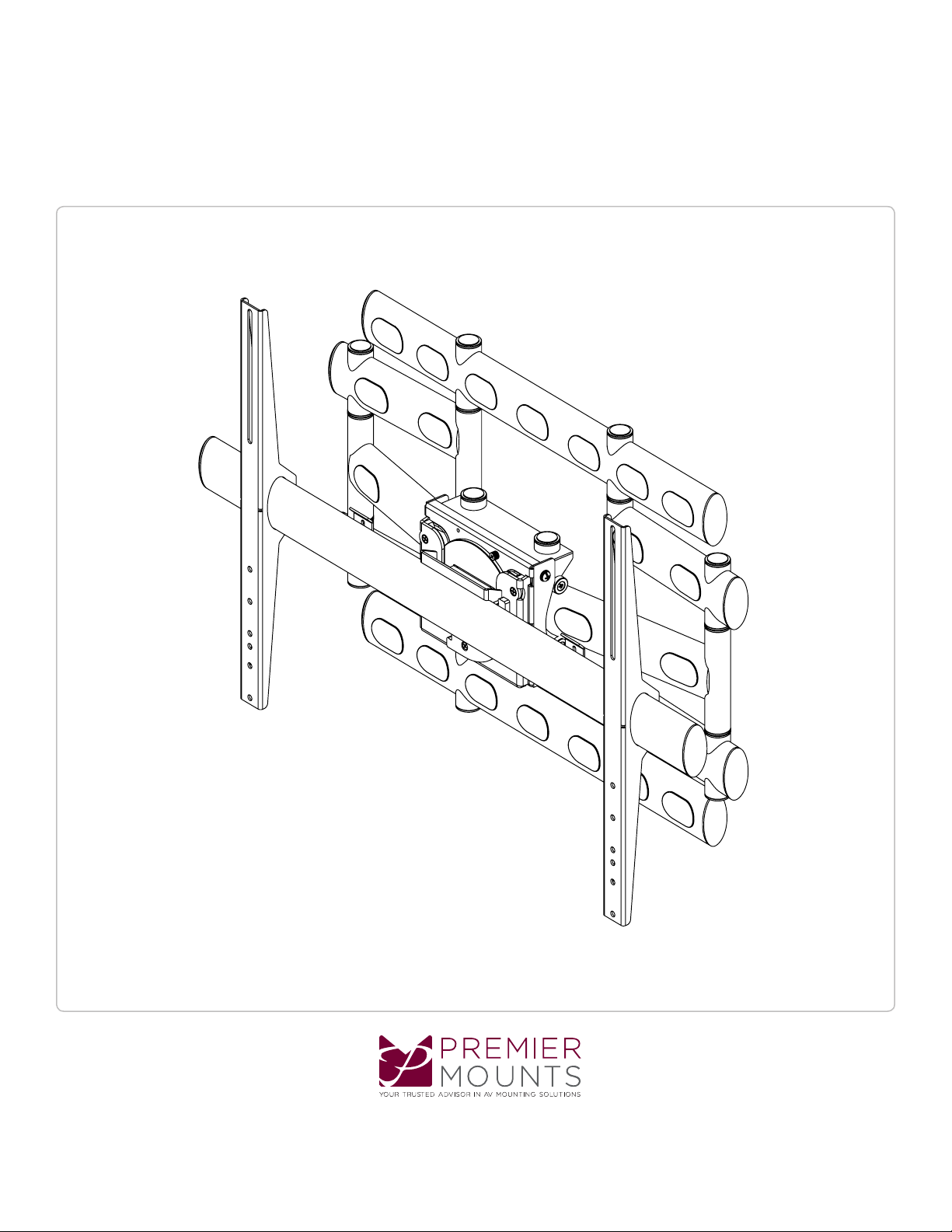
AM500-U
Installation Guide
www.mounts.c om | Nor th America 800.368.970 0 | International +1-714-632-7100
1321 S. State Co llege Blvd., Fuller ton, CA 92831 USA
Page 2
AM500-U
Installation Guide
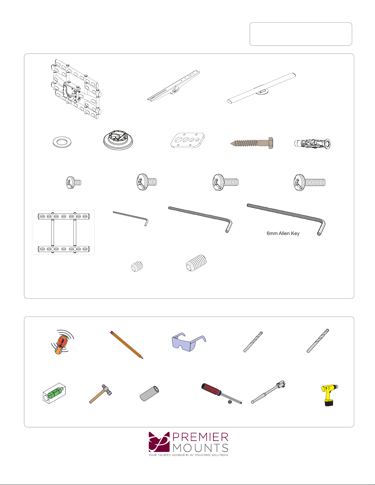
Included Components
Maximum Flat Panel Weight:
500 lb. / 226.79 kg.
5/16” Flat Washers
(Qty 6)
Template
(Qty 1)
Wall Mount
(Qty 1)
Universal Spacers
(Qty 8)
2.5 mm Allen Key
(Qty 1)
Bracket
(Qty 2)
Griplate™ Universal Washer
(Qty 4)
M8 x 20mm (Qty 4)M8 x 16mm (Qty 4)M6 x 12mm (Qty 4) M8 x 30mm (Qty 4)
5/32” Allen Key
(Qty 1)
5/16” x 3” Lag Bolts
(Qty 6)
6mm Allen Key
Cross Bar
(Qty 1)
Finned Anchors
(Qty 6)
(Qty 1)
M5 x 6 mm Set Screws
(Qty 2)
M8 x 10 mm Set Screws
(Qty 4)
Required for installation
Electronic Stud Finder 6mm or 1/4” Drill Bit
Level
Pencil Protective Eyewear
13mm or 1/2” SocketHammer
Phillips Head Screwdriver
Socket Wrench
3/8” Masonry Drill Bit
Portable Drill
Page 2
www.mounts.c om | Nor th America 800.368.970 0 | International +1-714-632-7100
Page 3
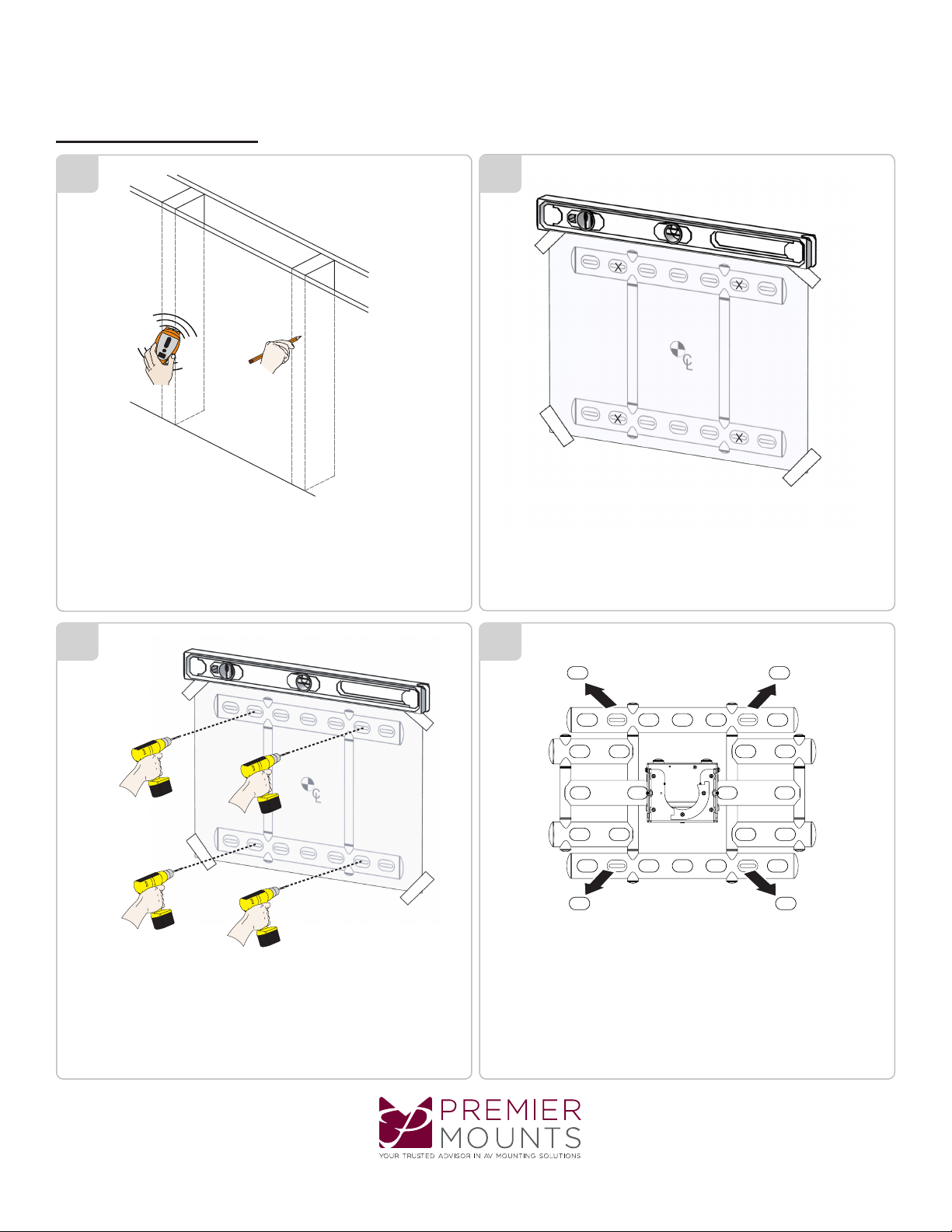
Wood Stud Installation
AM500-U
Installation Guide
1
X
X
1) Use a stud nder to determine the center of wall studs in
the vicinity of the mount.
2) Use a pencil to mark each of the wall studs.
2
1) Place the template over the wall.
2) Level the template.
3) Tape the template to the wall.
4) Mark four (4) mounting locations on template over the center of
the wall studs.
3
Drill four (4) pilot holes on mark locations with a drill gun and 1/4”
or 6mm drill bit.
4
Remove the caps from the wall mount.
www.mounts.c om | Nor th America 800.368.970 0 | International +1-714-632-7100
Page 3
Page 4
AM500-U
Installation Guide
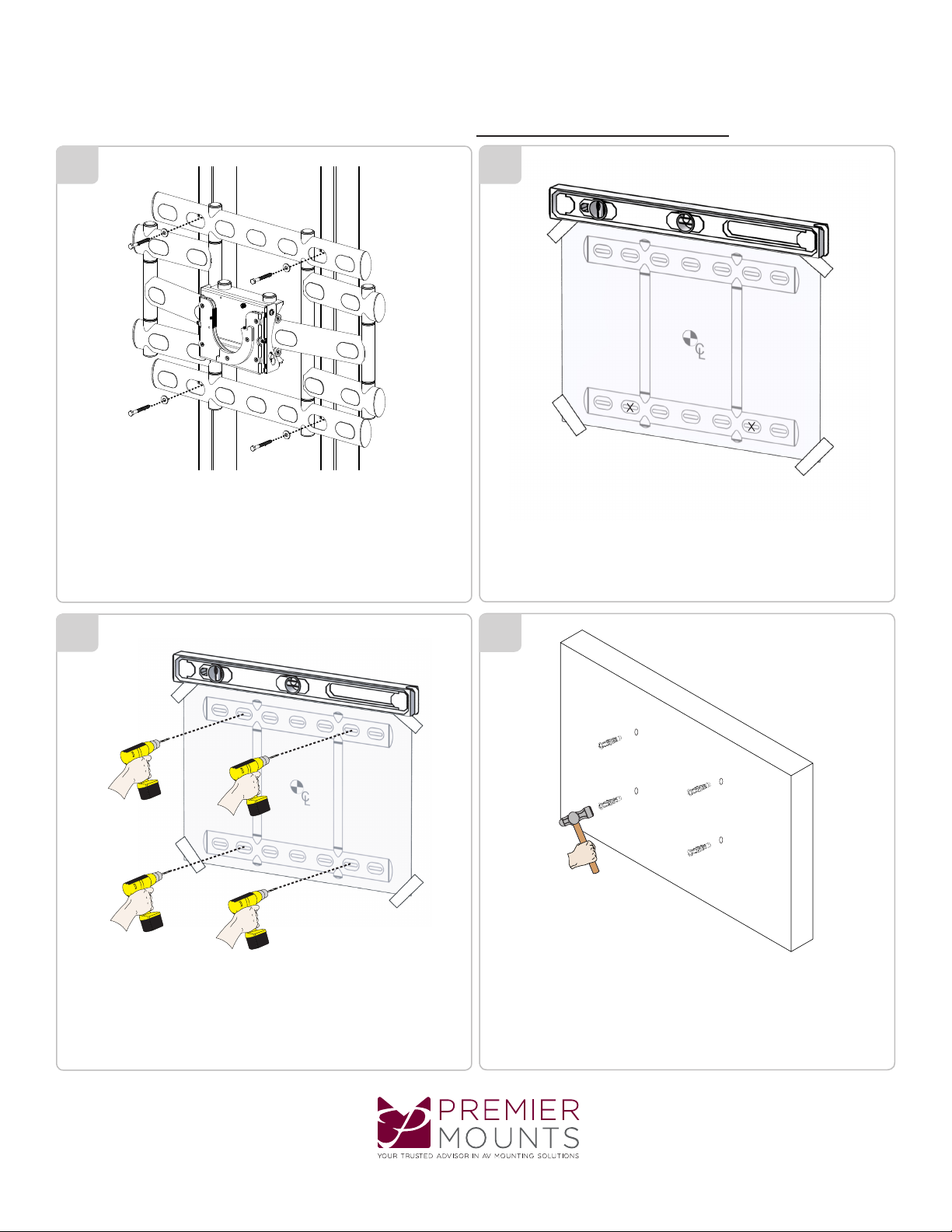
Concrete Wall Installation
5
1) Remove the template.
2) Place the wall mount over the pilot holes.
3) Insert one (1) lag bolt and one (1) washer into each pilot hole.
Tighten all lag bolts using a socket wrench and 1/2” or 13mm
socket.
6
1) Place the template over the wall.
2) Level the template.
3) Tape the template to the wall.
4) Mark four (4) mounting locations on template over the center of
the wall studs.
7
Drill four (4) pilot holes on mark locations with a drill and 3/8”
Masonry drill bit.
8
1) Remove the template.
2) Insert the Finned Anchors into each hole. Lightly tap each Finned
Anchors into place with a hammer.
Page 4
www.mounts.c om | Nor th America 800.368.970 0 | International +1-714-632-7100
Page 5
9 10
AM500-U
Installation Guide
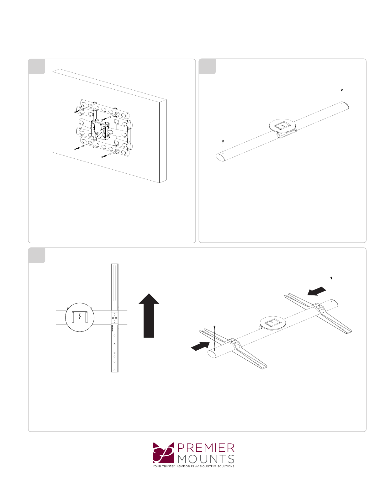
Insert the lag bolts and washer into the Finned Anchors. Tighten all
lag bolts using a socket wrench and 1/2” or 13mm socket.
11
Remove the two (2) M6 x 12 mm screws from the Cross Bar.
Locate the arrow on the Cross Bar and install the brackets
the correct direction as shown.
www.mounts.c om | Nor th America 800.368.970 0 | International +1-714-632-7100
1) Slide the brackets into the Cross Bar.
2) Secure the brackets with two (2) M6 x 12 mm screws removed
on steps 10.
Page 5
Page 6
AM500-U
C
L
Installation Guide
12
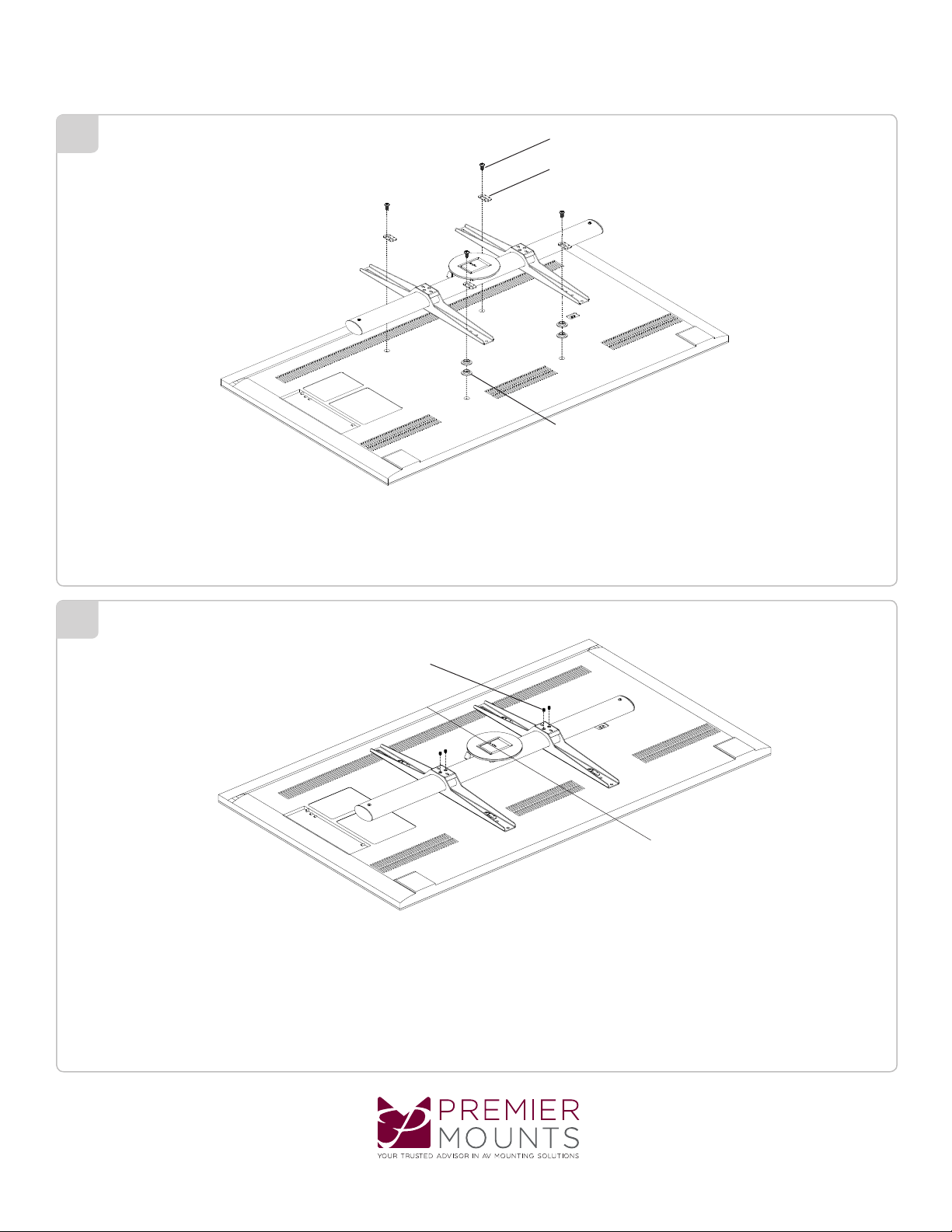
M8 screws
Griplate™ Universal Washer
Universal Spacers (Optional)
Align the brackets to the display mounting holes. Use four (4) M8 screws, four (4) Griplate™ Universal Washer.
Use Universal Spacers if necessary.
13
M8 x 10mm Set Screws
Center the cross bar to the display and install four (4) M8 x 10 mm set screws using the 5/32” Allen Key to secure
the brackets.
Page 6
www.mounts.c om | Nor th America 800.368.970 0 | International +1-714-632-7100
Page 7
14
AM500-U
Installation Guide
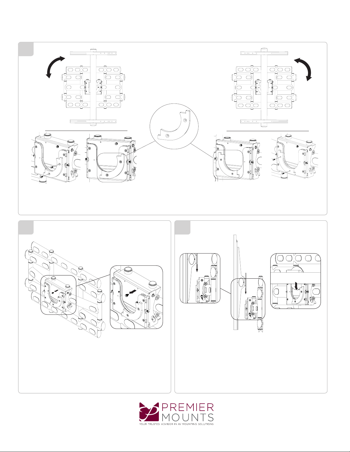
Rotational Bracket
Your orientation can be changed by switching your Rotational Bracket on the receiver.
15 16
Remove the 6mm safety knob screw and set it aside. Two or Three person is recommended for this step. Lift the
cross bar and place it into the receiver.
www.mounts.c om | Nor th America 800.368.970 0 | International +1-714-632-7100
Page 7
Page 8
AM500-U
Installation Guide
17
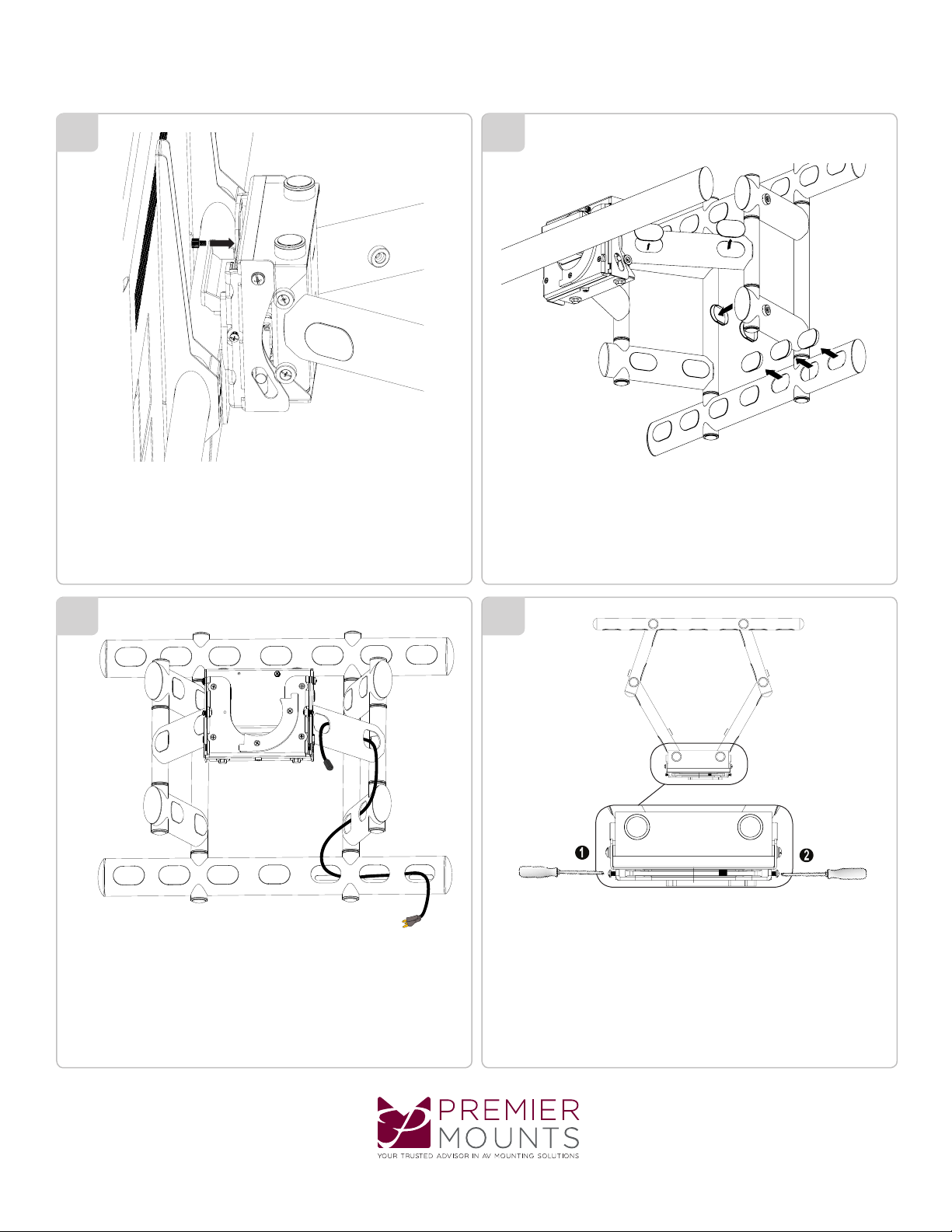
Once the cross bar is fully seated in the receiver reinstalled
the 6mm safety knob screw removed from step 15.
18
Remove the plastic caps.
19
Power and signal cables can run through the mount.
Note: Once cables have been installed carefully check the
movement of the mount and cables together to insure their
is no “pitching of the cables” when the mount is articulated.
20
The screws on the receiver head of the mount can be adjusted to
add or subtract the tension of the rotation.
Page 8
www.mounts.c om | Nor th America 800.368.970 0 | International +1-714-632-7100
Page 9
21 22
AM500-U
Installation Guide
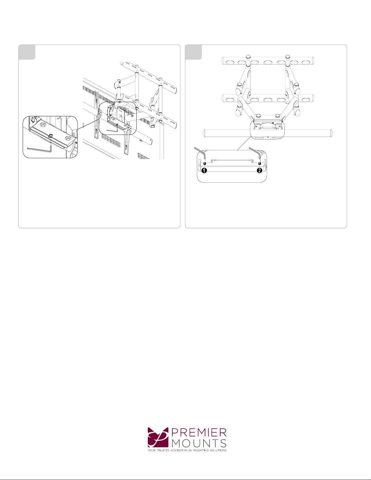
Use 6mm Allen Key for tilt adjustments. Use 2.5mm for leveling adjustments.
www.mounts.c om | Nor th America 800.368.970 0 | International +1-714-632-7100
Page 9
Page 10

AM500-U
Installation Guide
PREMIER MOUNTS
LIMITED LIFETIME WARRANTY
What and Who is Covered by this Limited Lifetime Warranty
Premier Mounts warrants all mounting products to be free from defects in material and workmanship
for the lifetime of the original installation of the product.
What Premier Mounts Will Do
At the sole option of Premier Mounts, Premier Mounts will repair or replace any product or product
part that is defective. If Premier Mounts chooses to replace a defective product or part, a replacement
product or part will be shipped to you at no charge, but you must pay any related labor costs.
What is Not Covered: Limitations
Premier Mounts disclaims any liability for damage to mounts, adapters, displays, projectors, other
property, or personal injury resulting, in whole or in part, from improper installation, modication, use
or misuse of its products.
NOTWITHSTANDING ANYTHING TO THE CONTRARY IN THIS WARRANTY, THIS WARRANTY
IS LIMITED TO FIVE YEARS FROM THE DATE OF PURCHASE IN THE EVENT THAT THE WARRANTED PRODUCT IS COMMERCIALLY RENTED OUT.
Electrical products and components, such as ampliers, speakers, motors, switches remote controls
and related electrical items, are backed by a 3-year warranty.
Premier Mounts disclaims all other warranties, express or implied, including warranties of merchantability and tness for a particular purpose. Premier Mounts is not responsible for incidental or consequential damages, including but not limited to, inability to use its products or labor costs for removing and replacing defective products or parts. Some states do not allow the exclusion or limitation of
incidental or consequential damages, so the above limitation or exclusion may not apply to you.
What Customers Must Do for Warranty Service
If you discover a problem that you think may be covered by the warranty, you must report it in writing to the address below within thirty (30) days. Proof of purchase (an original sales receipt) from the
original consumer purchaser must accompany all warranty claims. Warranty claims must also include
a description of the problem, the purchaser’s name, address, and telephone number. General inquiries can be addressed to Premier Mounts Customer Service at 1-800-368-9700. Warranty claims will
not be accepted over the phone or by fax.
Premier Mounts
Attn: Warranty Claim
1321 S. State College Blvd.
Fullerton, CA 92831 USA
How State Law Applies
This warranty gives you specic legal rights, and you may also have other rights which vary from
state to state.
Premier Mounts intends to make this manual accurate and complete. However, Premier Mounts makes no claim that the information
contained herein covers all details, conditions or variations, nor does it provide for every possible contingency in connection with
the installation or use of this product. The information contained in this document is subject to change without notice or obligation of
any kind. Premier Mounts makes no representation of warranty, expressed or implied, regarding the information contained herein.
Premier Mounts assumes no responsibility for accuracy, completeness or sufciency of the information contained in this document.
Page 10
www.mounts.c om | Nor th America 800.368.970 0 | International +1-714-632-7100
95 00 120 _1
 Loading...