


Sonic
9004 Remote Mount Siren Amplifier
Installation Instructions
9004-12-DE1 & 9004-24-DE1
Features Overview :
100W / 60W Speaker Outputs Horn switch polarity detection
Interlock input Relay driver output for horn bypass
Day & night volume levels Run input
Data output Fault indication
Reverse polarity protection Overheating protection
Over voltage protection Under voltage protection
Over Current protection Speaker short circuit protection
Approvals:
2004/104/EC as amended by (2009/16/EC)
Acoustic: KBA ABG , W 25057
ECE REG 10.4 E11 10R-04 7932
NPIA specification 5 (issue 11)
As part of our policy of continuous improvement we reserve the right to change
specifications without notice.
www.premierhazard.co.uk
Premier Hazard Ltd., YO16 4SJ, http://www.premierhazard.co.uk,
Tel.: +44(0)113 239 1111, E-Mail: info@premierhazard.co.uk
© 2013 Premier Hazard ltd. A member of the Public Safety Equipment group of companies
D00216-00-A
REL.39968
WARNING THE WORLD®
Emergency Service and Utility Warning Systems

2
Contents:
Features overview 1
Approvals 1
Safety information 2
Electrical Information 2
Tone Information 3
Fitting Information 3
Dimensional Drawing 3
In the Box 4
Features description 5
Wiring loom Information 6
Software description 7
Typical Installation diagram 7
Description of Positive and Negative HRT detection 8
Wiring a horn bypass relay 8
Wiring day and night volume switching 9
Wire size selection matrix 9
Fault codes and Troubleshooting 10
Safety Information:
Sirens are produced in 12 and 24 Volt versions. Ensure that you have the correct version for your
installation.
A suitable fuse and holder is provided with the siren amplifier wiring loom where bought.
Otherwise the recommended fuses are: 15A fuse – 12V version and 7.5A fuse – 24V version.
The Siren amplifier should be installed by an electrically competent person in accordance with
the fitting instructions.
Any wiring to or from the siren should be sufficient to carry the load, loads are given on page 6,
there is also a wire size selection matrix on page 9 which may aid this.
Sirens may get hot in use and they should be sited where this will not cause any hazards.
Consideration should be given to allowing air flow over the amplifier.
This equipment generates high levels of sound which may be detrimental to hearing. Care
should be taken during installation and testing so as to avoid endangering yourself or others.
Use of this equipment does not guarantee right of way over other road users and may not
always be heard by them. It should be operated only by trained and competent personnel.
Electrical Information:
Operating Voltage range 12V model: 11V – 16V
Operating Voltage range 24V model: 22V – 32V
Speaker requirements: 11 Ohm impedance, 100W
rms
loudspeaker
Standby current with power on < 20mA
Standby current without power on < 1mA
(Current consumption due to feeds on the input lines, such as the horn)
Maximum operating current: 10A
Ambient operating temperature range: - 30oC to + 60oC
3
Tone information:
Tone specification DIN 14610
Fitting information:
Leave room for airflow around the siren (approx. 50mm).
Don’t place any wiring directly on the siren casing.
The siren amplifier is not waterproof, so should be fitted in a suitable location.
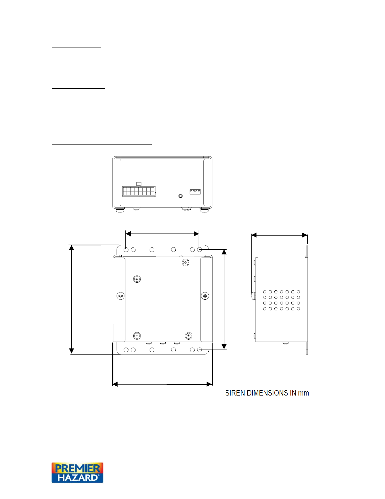
Siren amplifier dimensional drawing:
78.5
106.5
106
117
60
4
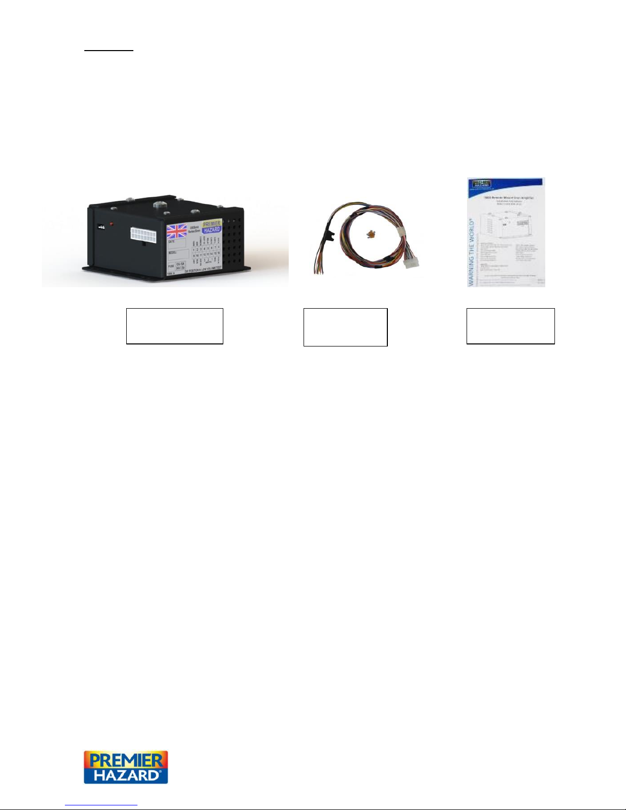
In The Box:
9004 siren amplifier Quantity x1 PH PN: 9004-12-DE1 or 9004-24-DE1
Installation Instructions Quantity x1 PH PN: D00216-00
Loom including fuse Quantity x1 PH PN: ME005-000-12V or ME005-000-24V
Note: an 11 Ohm impedance 100W speaker is required along with the siren amplifier to produce
sound. Please see page 14 for further details on Premier Hazard speakers, speaker cowls and switch
accessories.
Accessories:
12V change over relay SPDT PH PN: 562601
24V change over relay SPDT PH PN: 562602
9004-12 wiring loom kit PH PN: ME005-000-12
9004-12 wiring loom kit PH PN: ME005-000-24
Extra Brown / white cable for day & night volume PH PN: 507021
INSTALLATION
INSTRUCTIONS
9004 SIREN
LOOM
9004 SERIES
SIREN AMPLIFIER

5
Features:
Horn polarity detection – The siren amplifier detects if the horn is positive switched or negative
switched on start up. The HRT wire (pin 9) should be connected to the switched side of the horn (see
page 9 for full details).
Data output – This provides a 200mA positive output feed that can be connected to a data logger, the
data output is switched on when the siren is sounding and operating correctly.
Relay output – This provides a 200mA positive output feed that can be used to connect to a separate
relay (available separately) so that the Horn can be bypassed when the siren is operating.
This output is active when either the tone is sounding or when the run input is selected (see page 9 for
an example of the wiring).
Fault LED – The siren amplifier has a fault LED incorporated into the front panel to aid debugging and
trouble shooting of any faults. The LED will flash in different patterns to identify a particular fault (see
page 11 for fault codes and troubleshooting).
Circuit protection – The siren amplifier has the following protective circuitry incorporated into it to
ensure that fitting errors don’t cause damage to the siren or vehicle systems as well as:
Start delay – the siren will not work until three seconds after power is first applied to the
siren amplifier to allow voltage to stabilise after engine started, stopping damaging voltage
transients effecting the speaker.
Reverse Polarity protection – if the positive and ground lines have been reverse wired the
siren will not function, however the siren amplifier and speaker will not be damaged by this.
Over temperature protection – In the event of the siren overheating through excessive
prolonged use or extreme ambient temperatures. The siren will switch off the siren output
until it has cooled sufficiently to resume operation.
Over current protection – if the siren amplifier circuit is drawing too much current, caused
by a speaker failing or short circuit, the siren will switch off the siren output. The power to
the siren amplifier will have to be reset to clear this fault.
Speaker short circuit protection – if a short circuit is detected on the speaker the siren
output will switch off. The power to the siren amplifier will have to be reset to clear this
fault.
Over and under voltage protection – if the operating voltage is out of operating parameters
for the voltage version of the siren, the siren will not operate. i.e. when 12V siren fitted to
24V vehicle or if the vehicle battery is flat.

6
Wiring Loom information:
Pin No:
Wire Colour:
Function:
Wire rating:
1
Brown / white stipe
Speaker 100W output
10A
2
–
Speaker 60W output
10A
3
Brown
Speaker common output
10A
4
Gray
Not used on this version
1A
5
Blue
Relay output (Positive output, 200mA max)
1A
6
Not connected
No Function
–
7
Not connected
No Function
– 8 Pink
Data output (Positive output, 200mA max)
1A 9 Orange
Horn ring transfer input - HRT (pos. or neg. input)
1A
10
White
Interlock input (Positive input)
1A
11
Violet
Not used on this version
1A
12
Green
Not used on this version
1A
13
Yellow
Town / Country sound select (Negative input)
1A
14
Yellow / black stripe
Run input (Negative input)
1A
15
Black
Battery ground return
10A
16
Red
Battery power input
10A

7
Software description:
INTERLOCK
The interlock input needs to be connected to a positive voltage source for the tone to be able to
sound, such as a beacon interlock device. If not used connect to battery positive to enable tones.
HORN / FOOTSWITCH INPUT
Providing that the interlock input is connected to a positive voltage source, and that the siren isn’t
already sounding. Pressing the horn or footswitch will play a single sequence of the selected tone.
RUN INPUT
Connecting this to battery negative will cause the siren to play the selected tone, while connected,
providing that the interlock input is connected to a positive voltage source. Such as a beacon interlock
device or battery positive.
TOWN / COUNTRY SOUND SELECT INPUT
When this input is disconnected the Town sound will play (without vibrato) when selected either by
pressing the horn or connecting the run input to battery negative.
When this input is connected the Country sound will play (with vibrato) when selected either by
pressing the horn or connecting the run input to battery negative.
Typical installation diagram:

8
Positive & Negative HRT detection:
The Siren amplifier detects if the horn ring transfer is positive or negative switched at start up.
If the HRT input senses a positive feed it must be a negative switched horn, if it doesn’t sense a positive
feed it must be a positive switched horn. The HRT input just needs to be connected to the switched
side of the vehicle horn for the detection to work.
Occasionally there can be a problem when fitting over the top of an old system where a positive to
negative HRT change over relay has been fitted. As the siren amplifier is looking for a positive feed
when the horn is not pressed and no feed when the horn is pressed. Either connecting the positive
horn feed directly to the HRT input or wiring the relay as shown below should resolve this issue.
Wiring a horn bypass relay:
The diagram below shows how to connect the HRT input and relay output of the siren amplifier to
additional components to act as horn by pass for either a positive or negative switched horn.
Recommended resistor value: 10K, 0.25W, radial.
Key:
30 Common contact
87 Normally open contact
87a Normally closed contact
86 Coil positive input
85 Coil ground return

9
Day & Night Volume Switching
Below are two different wiring possibilities for wiring a switch to control the siren output for day and
night volume levels.
Day and night switching using relay Day and night switching using SPDT Switch
SPDT switch PH PN: 502
Note: SPDT switch can be used for both operations, when using SPDT switch it must be rated correctly
for the current passing through it (6A).
Wire size selection matrix:
Wire CSA
Maximum permissible current over distance
mm2 AWG
5A
10A
15A
20A
25A
30A
0.34
22
1.8m
0.9m X X X X
0.5
20
2.9m
1.5m
0.9m X X
X
0.75
18
4.5m
2.2m
1.5m
1.2m
0.9m
X
1.5
16
7.5m
3.5m
2.4m
1.8m
1.5m
1.2m
2.5
14
12m
6m
4m
2.8m
2.5m
2m
4
12
20m
9.5m
6m
4.7m
3.8m
3.2m 6 10
30m
15m
10m
7.5m
6m
5m
10 8 48m
24m
16m
11.8m
9.4m
8m
16 6 75m
37m
25m
18.8m
15m
12.6m
25
4
120m
60m
40m
30m
24m
20m
Wire Crimping
It is the purchaser’s responsibility to use a compatible crimping tool when fitting wire crimps ( PH part
No. 504304, manufactured by T.E. Connectivity, Man part No. 794956 – 1 ), to ensure correct quality
of crimp connections.

10
Fault Codes:
When the siren amplifier detects a problem with its operation it flashes the fault LED on the front of
the unit, fault patterns below. The fault light should be treated as a warning of improper operation and
possible causes should be investigated. The trouble shooting table below may assist with this, note this
is not intended to be an exhaustive list and is a guide only all work should be carried out by an
electrically competent person.
Flash Pattern
Detected Fault
Steady on
Short circuit on speaker detected
Steady flashing (on, off)
Over heated
Two flashes with a pause
Under voltage
Three Flashers with a pause
Over voltage
Four flashes with a pause
Over current, or short circuit
Troubleshooting:
Problem
Possible solutions
No siren tone output
Check power to siren
Check if fuse blown
Check speaker connected
Check run input connected (if required)
Fuse blown
Check cabling for shorts
Particularly wires passing through panels
Replace fuse
Fuse Keeps blowing when starting a tone
Check speaker cables for shorts
Check speaker resistance (should be 4.4R ± 1R)
Try running without speaker connected (tone should be
audible at siren, without blowing fuse)
Overheated fault indicated
Wait for siren to cool and operation should resume.
Check that siren has sufficient air gap to allow for air
flow.
Ensure that siren is fitted away from other equipment
that may get hot.
Under Voltage fault indicated
Check battery voltage (may be below 11V)
Check correct voltage version of siren is fitted
Check cabling is rated correctly (if under rated may have a
voltage drop down line)
Check ground return to battery (ground could be
unstable)
Over Voltage fault indicated
Check correct voltage version of siren is fitted
Check battery voltage (may be over charged)
Check alternator is attached to battery correctly
Over Current fault indicated
Check speaker resistance (should be 4.4R ± 1R)
Check speaker cable for shorts
Check alternator connected to battery
Check power to siren (could be unstable, due to
alternator problem, grounding, cabling or another device
fitted to vehicle)

11
NOTES:

12
WARNING THE WORLD®
Emergency Service and Utility Warning Systems
9004 SIREN AMPLIFIER ACCESSORIES
wwemierhazard.co.uk
Premier Hazard Ltd., YO16 4SJ, http://www.premierhazard.co.uk,
Tel.: +44(0)113 239 1111, E-Mail: info@premierhazard.co.uk
© 2013 Premier Hazard ltd. A member of the Public Safety Equipment group of companies
SPEAKER
PA100-R
SPEAKER & FLUTE
R – SPEAKER COWL
S – SPEAKER COWL
C – SPEAKER COWL
L – SPEAKER COWL
502
504
509
509A
SWITCH PANELS
M – SPEAKER COWL
SONIC WIRING HARNESS
ME005 SERIES
IMAGES NOT
TO SCALE
 Loading...