

Page 1

INSTALLATION
GUIDE
Suggested guidelines
for the preparation and
installation of Premier
Structural Insulated Panels
Stronger. Straighter. greener.
Page 2

Introduction
Premier Building System’s SIPs Installation
Guide has been divided into convenient sections
covering most aspects of PBS SIPs installation.
Designed for carpenters, framers, contractors
and do-it-yourselfers, the instructions and
detailed illustrations will give you the basics of
building with PBS SIPs at just a glance.
Premier’s SIPs installation techniques are
based on Premier Building Systems’ continuing
program of independent, third-party testing and
more than 30 years of fabrication, installation,
and innovation.
If you have questions about anything covered in
this installation guide, please call us and ask to
speak with a technical representative. A listing
of Premier’s office phone numbers appears in
the back of this guide.
Stronger. Straighter. greener.
2
Page 3

Table of Contents
PBS SIPs Tips .......................................... 4
Storage & Handling ..................................6
Checklist of Tools ..................................... 7
Spline Connection ....................................8
Lumber Connection ..................................9
I-Joist Connection.... ............................... 10
Panel Basics – Assembly ........................ 11
Fasteners .............................................12
Field Fabrication .................................... 12
Fabrication Rake/Gable Walls .................14
Floors .................................................... 15
Sill Plates .............................................. 18
Walls .....................................................20
Headers ................................................24
Intermediate Floors ................................26
Roofs ....................................................28
Insul-lam ............................................... 32
Electrical ...............................................33
Plumbing ............................................... 35
Shearwalls .............................................36
R-Values ................................................ 37
Load Values ..........................................38
3
Page 4

PBS SIPs Tips
• Project must meet local code.
• Confirm your installation date at least two
weeks prior to requesting on-site assistance.
• Schedule a preconstruction meeting with
your installation crew (concrete, plumbing,
electrical, siding, roofing, etc.).
• Inventory materials when you receive them.
• Check all SIPs for proper cuts and recesses.
• Double check SIPs sizes and compare to
shop drawings before installation.
• Engineered details take prescedence over
PBS details.
• PBS details regarding mastic and SIPs tape
need to be followed.
• Any changes required at the job site should
be communicated with the technical
representative.
• Make sure your foundation or floor is level
and square.
• Fabricate and pre-install dimensional or I-joist
spline material as specified.
• Review engineering for hold downs if
applicable.
4
Page 5

• Make sure to drill the top and bottom
plates for the vertical electrical chases in
the wall panels.
• Do not put plumbing inside SIPs.
• Do not cut the skins (OSB) for extra
electrical chases or plumbing.
• Do not pick up the SIPs by the edge of the
top skin.
• Remove debris from sill plate before you
place the SIP wall panel on it.
• Use mastic on all connections as shown in
the PBS details.
• Make sure that both of the wall SIPs skins
are bearing on the floor.
• Follow proper nailing requirements according
to details and job specific engineering.
• Plumb each SIP in each direction, then secure
with nails.
• Fill all voids with expanding foam.
• Do not apply interior or exterior materials
over wet SIPs.
5
Page 6
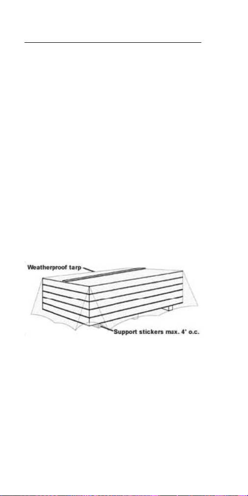
Storage & Handling
Your panels will usually arrive on a flatbed
truck. Depending on the site, panels should be
off-loaded to a clean, flat area with sufficient
maneuvering room. (A fork-lift will speed the
off-load process.)
Panels do not come in any particular order. This
allows for minimized shipping costs by taking
full advantage of the space available on the
truck. It is advisable to sort the panels as you
off load them. This process will require room to
shift and stack the panels accordingly.
Sort and stack all of the panels by panel ID
number and move them as close to their final
location as possible. Place at least three
stickers a maximum of 4’ on center (o.c.) under
the panel stacks to ensure that the panels
remain flat. The stickers should be a minimum
of 3 ½” wide.
Inventory the panels as you off-load them.
If one is missing or damaged call PBS
immediately. We will work to correct the
problem as soon as possible.
Remember, you are working with a wood product
that may swell after prolonged exposure to
moisture. Keep all panels and accessories
protected from the elements prior to installation.
If splines swell, installation may be hampered.
6
Page 7

Checklist of Tools
• One or two 29 oz. caulking guns
• Hand saw
• Pry bars
• Sledge hammers
• Mineral spirits
• String line
• Lifting eyebolts
• Lifting plates
• Framers square
• Loose 8d and 16d sinker nails
• Dunnage for supporting panels
• Expanding foam
• Fall arrest gear for roofs (if applicable)
• Chalk line
• Levels (4’ or longer)
• Two 5’–6’ 3/4” bar clamps
• Paint scrapers
• Ladders—step & extension
• Come-along with 2” trucking ratchet straps or
• A device similar to Jimmy’s Strapjack Panel
Puller for pulling panels together
• 1/2” drill motor for 1 1/2” diameter
electrical chase holes
• 1 1/2” x 12” auger bit
• 1 or 2 3/8” drill motors
• Chain saw with 14”–16” bar and chain saw
guide for site fabrication
• One or two circular saws
• Power planer
• Foam Scoop and/or Avalon hot knife
• Bits for panel screws
• Nail gun or 1/2” crown staple gun
• Reciprocating saw
7
Page 8
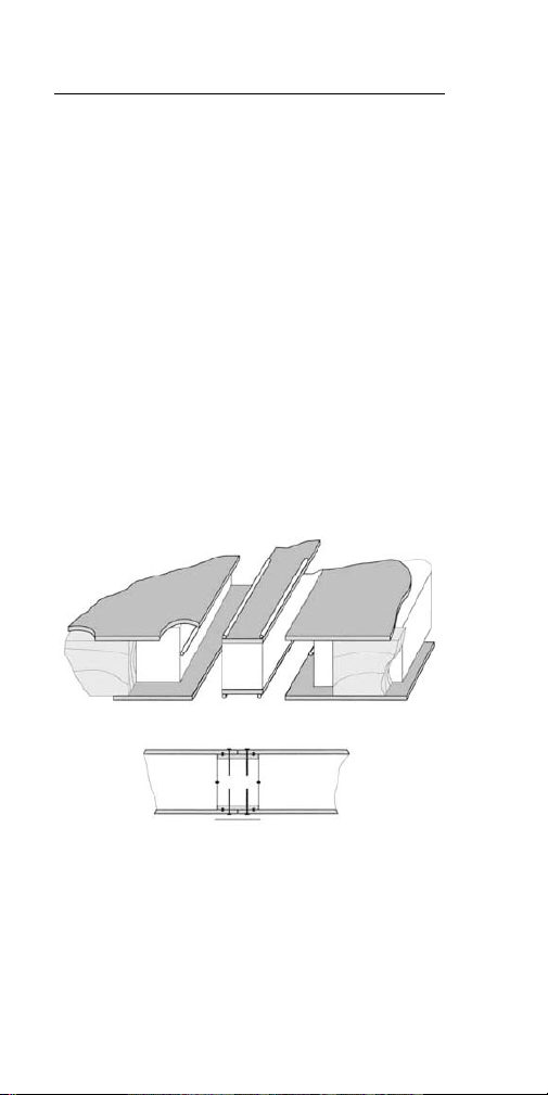
Spline Connection
Depending on the load requirements and
application, Premier Panels are joined together
in one of three fashions: Premier spline (Type
‘S’ panel), lumber spline (double 2x or 3x, Type
‘L’ panel) or engineered I-joists (Type ‘l’ panel).
Premier splines – This is the most common
connection between Premier Panels. Splines
should be cut flush or slightly short (about
1/16”) of the foam in the panel ends. Parallel
3/16” beads of Premier Mastic are placed
approximately 1/4” from each of the spline
edges and along the foam-to-foam edges.
Premier Mastic is used on all wood-to-wood,
wood-to-foam, and foam-to-foam interfaces.
Once panels are in place, the splines are nailed
with 8d nails 6” o.c. or according to your shop
drawing nail pattern.
8
Page 9

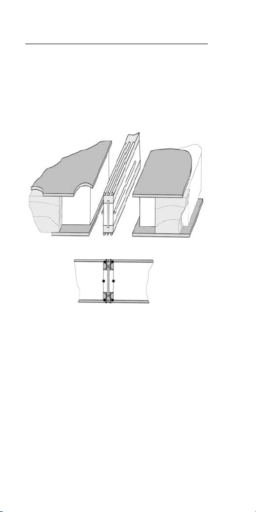
Lumber Connection
Lumber spline – PBS panels are designed to
accept kiln dried lumber set into a standard
1 1/2” recess along the bottom, top, corners
and window openings of the panels. Simply
cut the plates to length, apply a 3/8” bead of
Premier Mastic between plys of the dimensional
spline and nail dimensional splines together.
Apply a 3/8” bead of Premier Mastic along
the sides and center of the recess, set the
lumber into the recesses and nail off through
the skins with 8d nails 6” o.c. or according
to your shop drawings. The lumber should
remain flush with the edges of OSB. If your
lumber has swelled, it may be necessary
to chamfer and trim the piece so it will fit
properly. Always dry fit the dimensional
lumber before applying Premier Mastic.
9
Page 10
I-Joist Connection
I-Joists – These are mainly used in roof and
floor connections. Premier Mastic is applied
to the outer edges of the flanges prior to
placement in the panel recess. Expanding foam
is applied on both sides of the web to ensure a
proper seal with the panel.
10
Page 11
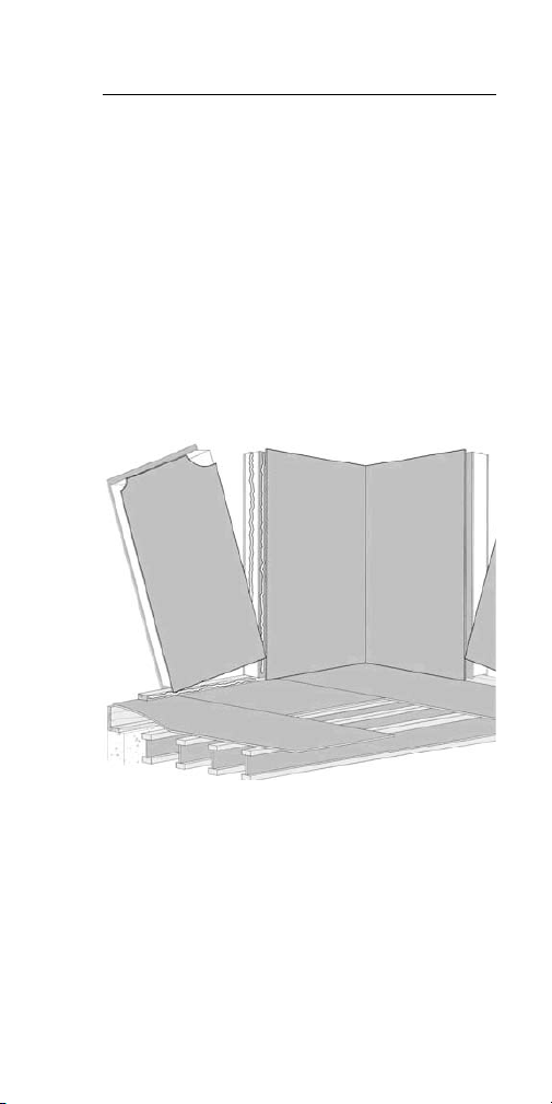
Panel Basics – Assembly
When assembling wall panels, whenever
possible, use a scissor-like motion to place
the panels. To do this, push the bottom
corner so that the skins touch. While holding
the top of the panel out about 24” brace
your foot on the bottom of the panel, then
push the top into place. Be sure to watch
your fingers. If you have difficulty getting
the panels together, use either trucking
straps, bar clamps or dunnage and a sledge
hammer with enough force to bring the panels
together. Jimmy’s Strapjack Panel Puller can
also be used to pull the panels together.
11
Page 12

Fasteners
Typically, an 8d nail 6” (o.c.) is used to connect
panels to top and
bottom plates at
spline connections
and for dimensional
plating. Staples are
permitted, provided
they meet the
following criteria:
Minimum length =
1.5” 14 gauge
@ 6” o.c., 16 gauge
@ 4” o.c.
Field Fabrication
Field fabrication will be necessary on the site
if you ordered stock panels. Even on factory
fabricated panels, slight field modifications
may be necessary to allow for panel growth
or variations in the actual field dimensions.
Modifications are not difficult. Common
construction tools will suffice for most projects
with the only additional recommended tool being
a foam scoop/hot knife (available for purchase)
for quick and easy recessing of the foam core.
When performing field modifications to
panels, wait to make measurements and
modifications until the previous panel has
been placed into its final position. When
cutting wall panels, make sure you have
the correct panel, and that it is PROPERLY
ORIENTED (horizontal electrical chases are
at the bottom of the panel). Remember to
take an extra 1/8” off the desired dimension.
We recommend using a pencil to mark your
lines on the panel skin, as chalk lines tend
to blow off when the saw blade approaches.
12
Page 13

Metal straight edges can be helpful. For
fast, accurate cuts that are close to a panel
edge, use ripping guides for circular saws.
If you are using a circular saw, lay out one face
and then square it across the panel skins to
transfer your mark to the opposite skin before
making your cut. Use the maximum depth
of cut setting on your saw and make a nice
straight cut. Flip the panel over to layout that
side and make a similar cut.
The remaining foam between the panel skins
can be cut using a reciprocating saw, or hand
saw. When using a reciprocating saw use a
dull blade, it will follow the kerf cut in the panel,
cutting the foam without slicing the wood.
Scrape off any excess foam between the skins
with a metal straight edge such as a speed
square. Adjust your foam cutter to the depth of
the installed member. (Foam cutters will melt
foam back further than the setting, which is
just about the right tolerance to get the framing
member into the panel.) After your foam is
“scooped” out, clean the leftover foam along
the sides by placing the foam cutter parallel
with the skin. (The depth gauge can rest on
the panel edge.) Use a paint scraper or speed
square to take off any excess foam that may
inhibit lumber placement. Use Premier Mastic
as required and follow the appropriate details
outlined in this manual or the PBS detail section
of our website at: www.pbssips.com.
13
Page 14

Field Fabrication
Rake/Gable Walls
Rake/Gable Walls – are easily calculated and
laid out on the panels. First, establish the short
side dimension. Next, mark this measurement
on both edges. Draw a line horizontally across
the panel. The rise across the panel will be
determined by your roof pitch. If your panel is
4’ wide, multiply the roof pitch by 4’ to get your
rise (in inches) on the other side of the panel.
For example, a 6:12 pitch will gain 24” (4’ x 6”
= 24”). An 8:12 pitch has a rise of 32” (4’ x
8” = 32”) and so on. Again, square across the
panel skins prior to making your cut. (Flipping
the panel is easier if you layout and cut your
panels on a sawhorse.) Recess the foam to the
appropriate depth.
14
Page 15

Use the long point of one panel to establish the
short point of the next adjoining panel. Add a
small amount to this measurement to allow for
the required 1/8” gap as determined by the roof
pitch factor. Continue on to the ridge or highest
point. After all rake walls are erected, small
adjustments can be made to make the plane
of the rake flat: either plane off the high spots
on the rake panel skins and re-cut the foam, or
just raise the plate slightly to get a straight line
along the rake/gable.
Recesses can be melted out of the foam when
the foam cutter is placed perpendicular to the
skin and the depth gauge is set to 1-1/2”.
Make sure to blow out the loose foam with
an air nozzle or scrape the recess out before
installing splines.
ALL FLOOR, WALL AND ROOF PANELS CAN BE
FIELD CUT USING THE PRINCIPLES DESCRIBED
HEREIN. DIRECT ANY QUESTIONS TO YOUR
SALES PROFESSIONAL OR THE PREMIER
LOCATION NEAREST YOU.
Floors
Before placing panels, pre-assemble the
dimensional lumber, or I-joists, and install them
into the edge recesses along the leading edge
of the panel. Use 5’ bar clamps (if necessary)
to help pull twisted lumber flush to the panel
edges. Nail both sides of the panel 6” o.c.
Premier splines can be installed as you set
each floor panel. They should be placed on the
trailing edge of the installed panel. The Premier
splines should be placed into the recesses as
the panels are being installed. Apply Premier
Mastic as described in the connection section.
15
Page 16

Use only one nail into each 4’ spline to hold it
in place. Do not nail off the spline until the next
panel is in place. Refer back to the connections
section for proper mastic placement.
Before placing the panels on the floor support
beams, tack a dry-line spaced 1/2”–3/4” out
from the entire length of the support beam.
Use temporary bracing to help hold these
beams in place. When setting the panels, make
sure the beam stays straight by checking your
string line.
Start by placing your first panel on a corner.
Use Premier Panel Screws as shown on the
shop drawings or described by the engineer
of record, to attach the first panel to the
supporting beams. Do not tighten the screws
on the edges of the panels until your rim board
is in place. Also, leave the last two screws on
the leading edge loose until you have set your
next panel. Once the next panel is in place,
screw the previous one tight and repeat the
process. Install blocking for point loads per
engineered plans as shown above to the right.
16
Page 17
PREMIER SPLINE OR
OTHER PANEL
CONNECTION AS
REQUIRED BY DESIGN
FULL BEARING
BLOCKING
REQUIRED UNDER
POINT LOADS
CONTINUOUS
RIM BETWEEN
SUPPORT MEMBERS
PREMIER SPLINE
OR OTHER PANEL
CONNECTION AS
REQUIRED BY DESIGN
8d NAILS @ 6" O.C.
OR EQUIVALENT U.N.O.
PANEL TIP > Stagger your panel placement
with two panels on one side of the beam, four
panels on the other side, and four back on the
first side of the beam. This will help your beam
stay straight.
Assemble floor panels using a scissor action.
Use the truck ratchet straps or a device like
the Jimmy’s Strapjack Panel Puller to help pull
panels together as needed, you can also try
using blocks of wood and a sledgehammer.
After all the panels are in place, install the rims
using Premier Mastic. Refer to PBS details
for the location of the sealant on the rim.
Check for proper Panel Screw placement and
spacing. Tighten all screws. Make sure to nail
off the tops and bottoms of all the floor panel
connections as well as the entire perimeter of
the floor panels.
17
Page 18

Sill Plates
Check your bottom plates to see if they are all
the same dimension in width. Install all of the
sill plates level ( ± 1/8”), square (within a 1/4”
of being square on the longest diagonal), and to
the exact dimensions of the layouts on the shop
drawings. When placement of the wall panels
is directly on top of a concrete foundation,
remember that because the panel skins cannot
bear directly on the concrete, a capillary break
and solid bearing is required.
One of the best methods to provide a capillary
break is to use a treated sill plate that is either
equal to the total thickness of the panel or
slightly wider.
Take your time and do a good job when you lay
out the sill plates. Time spent now will save
you time throughout the rest of your project.
When you lay out the sill plates, always use
the longest building line to establish the base
line. Use this base line to establish the largest
perpendicular building line available and make
it square to the base line. Be exact. Use a
calculator or the largest ratio of a 3-4-5 triangle
to do this. Measure parallel to either of these
reference lines for all other smaller dimensions
that are within the structure. Adjust or shift sill
plates as required on the foundation system to
match all the desired dimensions on the panel
layout drawings.
Snap a chalk line on the foundation wall for the
inside of the sill plate and begin setting your
plates. Use an appropriate sill sealer under the
sill plates. Level the plates as required.
18
Page 19

If the plates are not laid out to the exact desired
dimensions and within 1/8” of level, extensive
panel modifications may be required later.
Dimensions for the foundation and sill plates
(and the walls that follow) are usually the same
as the exterior of the wall panel skins—not
the lumber plate that is inside them. This
is different from stick framing where the
dimensions usually refer to the outside edge of
the framing member.
19
Page 20

Walls
Time should be spent to organize the job site.
Set out the panels in the order you are going to
use them. Get all your tools onto the floor deck,
including:
• Foam scoop
• Marker
• Flat dolly—for moving panels around the deck
(A come-along or truckers ratchet straps is
not needed, but may prove useful.)
STEP 1. BOTTOM PLATE
Wall panels are placed over a dimensional
bottom plate that fits in the recess in the wall
panel. Refer to your panel layout drawings for
the location of the bottom plate. The plate will
be measured 1/2” in from the outside edge
of your floor. Snap a chalk line on the floor,
equal to the plate width + 1/2” to represent the
inside edge of the bottom plate. Panel skins
should run flush to the floor edge. Apply double
3/8” lines of Premier Mastic 1” from the edge
of the plate and nail it off with (3) 16d nails per
floor joist or 12” o.c. to floor system below, or
as required by code.
20
Page 21

STEP 2. LAYOUT TRANSFER
Using a black marker, transfer the panel layouts
to the bottom plate. Include all window and
door openings as well as the vertical electrical
chases in each wall panel. If electrical chases
are being utilized, drill the chase holes as you
set each panel using a minimum 1 1/2” bit.
(Do not drill all the chase holes down the entire
wall, because as panel joints grow you will be
off center as you get to the end of the wall.)
STEP 3. PANEL TILT
Determine the best place to start the
installation and get your panels to that area.
Most of the time it is best to start in a building
corner. The corners are locked together using
Premier Panel Screws secured through the
panel spaced 2’ o.c. maximum. (Normally you
will use a screw two inches longer than the wall
thickness.) Install the screws into the panel
close to the lumber plate. Use a drill to finish
tightening and the panels will cinch together.
Set the underside of the screw heads flush with
the OSB, do not break the skin of the panel.
Always check the fastening or engineering
schedule on your shop drawings.
21
Page 22

Check the panel dimensions
against the floor layout.
Apply a 3/8” diameter bead
of Premier Mastic along the
sides and down the center of
the bottom plate. Slide the
panel into position. Lift the
panel over the bottom plate
by using either manpower or
mechanical means. After the
panel is standing, check for proper placement.
Next, plumb the wall section in both directions
and fasten it to the plate and the adjacent
panel with the specified fasteners. If necessary,
brace the wall before moving to the next panel.
STEP 4. ADJACENT PANEL
Move the next panel into position and apply
Premier Mastic in the same manner as with
the first panel. On this panel you will run
an additional 3/8” diameter bead of mastic
down the center of the foam-to-foam interface.
Place splines on the floor and run the Mastic
down one side and up the other, approximately
1/4” from the edge on the spline.
22
Page 23

Set the splines into the grooves of the fixed
(standing) panel. Bring your connecting panel
into position over the bottom plate, tilted slightly
away from the fixed panel. Butt the skins
together at the bottom and scissor the walls
together using a sharp motion.
STEP 5. FASTENING
Plumb the panel in both directions. It may be
necessary to tack the bottom of the panel to
hold it in place while the plumbing process
takes place. Once the panel is plumb in both
directions, nail both sides of the spline seam
and the sill plate with 8d nails at 6” o.c. (You
may have to brace the wall.)
STEP 6. TOP PLATE
Repeat the procedures for the remaining wall
panels. When you get to a corner or opening
make sure to check the panel dimensions
before standing the panel. (This panel may
need to be trimmed to fit the location properly.)
23
Page 24

After all of the walls are up, prior to setting
your top plate, check and plumb the alignment
of each wall, getting as close to square and
plumb as possible. If electrical chases are
being utilized, mark the vertical chases onto
your dimensional lumber top plate. Cut the top
plate so that the ends of the top plate have a
minimum 2’ overlap with the wall panel seams.
Apply a 3/8” diameter bead of Premier Mastic
down the center and along each edge of the
wall panel recess. Set the top plate and nail it
off according to the engineering specs, (usually
8d nails 6” o.c.) finish by drilling the electrical
chase access with a minimum 1 1/2” auger bit.
Headers
Depending on the engineering requirements of
your windows and doors, Premier’s Insul-Beam II
can be used in place of double 2 x 12s in spans
up to 16’.
Determine trimmer height: depth of the header
+ the top plate + bottom plate - height of
panel = height of trimmer (11 1/4” + 1 1/2”
+ 1 1/2” - 96” = 81 3/4”). Cut your trimmer
and cripple, apply Premier Mastic and nail
them together. Slide the pieces into the panel
recess. Next, install the panel that sits below
the window. Put your trimmer and cripple into
24
Page 25

this panel. Set the next panel into place over
the bottom plate and tip it into its final position.
Measure the total depth of the header required
and add any sheathing or plating to the top or
bottom of the header to achieve this dimension.
Measure the maximum length the header can
be and cut the header 1/8” short of this, taking
care to avoid the nails in the Insul-Beam II as
you cut.
Apply Premier Mastic to the insides of the
opening and drop the Insul-Beam II horizontally
into place. Do not nail the panel skins to this
header yet. Apply Premier Mastic to the top of
the panel, down the center of the Insul-Beam II
and inside both ends.
25
Page 26

Cut your panel top plate to be continuous over
the opening and at least 1’ past each end of
the opening and 1’ from any panel joint. Install
the top plate into the panel recess and over the
header. Nail the top plate to the Insul-Beam II
first with 2 16d nails 12” o.c. Nail the panel
skins on either side of the header to the top
plate first then down the sides of the panels
along the Insul-Beam II.
Fur out both sides of the Insul-Beam II with
7/16” sheathing to match the thickness of the
panels, keeping the sheathing flush with the top
of the top plate.
Intermediate Floors
PLATFORM FRAMING
In typical platform framing, the rim is placed on
top of the panel, flush to the exterior, and the
joists are placed on top of the panel.
(Floor joists can be either engineered wood
or dimensional lumber. For more information,
refer to the “Floor” section of this guide
and the PBS detail section of our website at
www.pbssips.com)
26
Page 27

Another option: Once the top plate is in, you
may now also hang joists directly from the wall
panel. Use a joist hanger with a nailable top
flange. The flange should bear at least 1.5” (2”
is best) on to the top plate. Nail the top flange
following the fastening schedule specified by
the engineer.
As always, consult with your engineer of record
concerning your specific design requirements.
27
Page 28

Roofs
Upon receiving your roof panels, count them
and check the sizes. In most cases roof panels
are not fabricated at the factory because roofs
tend to vary from the shop drawings. If they
have been factory fabricated, double check
for accuracy. Also, check the edge treatment.
You may have to plane your lumber or I-joists
to fit the recesses. If the panels aren’t being
installed immediately, cover the panels and
lumber until ready for installation.
28
Page 29

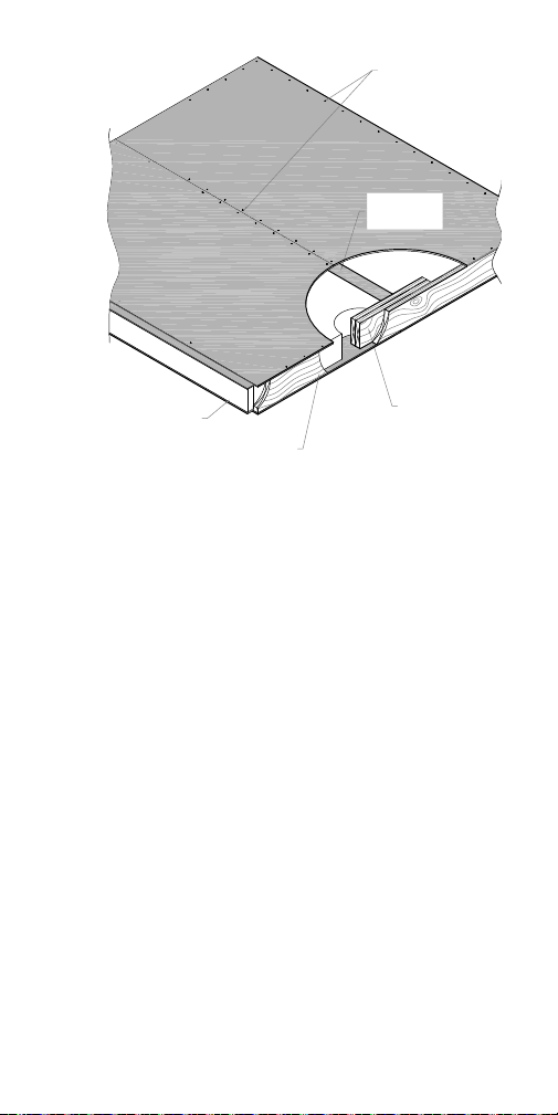
ON THE GROUND
Prior to lifting, install as many of your
dimensional lumber splines and I-joist splines
as possible along the connecting sides of each
roof panel. Premier splines should be installed
as panels are installed. The dimensional
lumber at the ridge and eaves should be
installed after the panels are set in place. (If
panels are perpendicular to the ridge.)
Cut a bevel block out of dimensional lumber to
the same pitch as the roof and fasten the full
length of the ridge. The roof panel must bear at
least 1 1/2” on the beveled block. Next, tack
SIP Tape that is 18” wide on top of the ridge
beam. (Be sure that the release paper is facing
up towards the underside of the roof panels.)
LIFTING PANELS
Use either a picking eye or strap
method to lift your roof panels. (A
lifting apparatus can be fashioned
from a 4” eye made from 3/4” steel
rod.) The shaft should be at least
14” long. The nut should be tack
welded to a minimum 4” diameter
washer made of 1/2” thick steel.
29
Page 30

Use a lifting plate that is 12”x12”x3/16” with
a 4x5 grid of holes to attach screws through
and into the OSB skin of the panels. (The
plate should have a “U” welded to it to fasten
the lifting device to.) A minimum of two plates
should be used to lift each panel.
Determine the center of each panel. Depending
on the pitch of the roof, drill your hole for the
picking eye, or place the center of the two lifting
plates, 3” from the center of the panel toward
the ridge end for every pitch change after 4:12.
For example: On a 7:12 roof, the lifting hole will
be 9” from the panel center. This will allow the
panel to arrive on the ridge at almost the proper
pitch, which will help the panel installation. If
you use the picking eye, be sure to fill the hole
with expanding foam sealant prior to installing
roofing felt. (If the roof panel has installed
lumber, the placement of the lifting eye or plates
may need to be adjusted.)
During the install, it is recommended that
you alternate the placement of the panels
on either side of the ridge beam. Start with
two panels on one side of the ridge, then
four on the other side. To help prevent
the ridge beam from bowing, alternate this
sequence for the balance of the roof. To
make placement of adjacent panels easier, do
not fasten the last screw tightly at the ridge
or eave of the leading panel edge, as it It
may become difficult to place the next panel
due to compression from the last screw.
In some wall/roof connections, as shown on the
previous page, the electrician can run the wires
in the void created by the beveled block. Once
the wires are in place, spray expanding foam in
the void or use an EPS wedge infill.
30
Page 31

Valley Connections – Premier Panels can be
used in hips and valleys. Consult with your
Premier Sales Professional and the Premier
Detail manual for more information.
Ridge Cap – Begin by trimming off 1/2” from the
bottom of the ridge cap point. Spray a high-yield,
expanding foam into the bottom and along the
sides of the ridge and set the ridge cap in place.
Adhere two strips of OSB to the top of the ridge
using Premier Mastic and Panel Screws.
Vapor Retarder – An appropriate vapor
retarder must be installed on the interior
of the roof panels. Premier recommends
using SIP tape on the panel joints and
at the wall to roof connections. Refer to
Technical Bulletin #28 at www.pbssips.
com for more information on this subject.
31
Page 32

Insul-Lam
Insul-Lam is used as a non-structural nail base
in either a one or two layer system.
Two-Layer System – Begin by installing the
2x dimensional lumber dam around the
perimeter of the roof. The height of the dam
is determined by the depth of Insul-Lam being
installed. In residential applications, PBS
recommends the use of a vapor retarder with
either the one or two layer systems. You
will need to cut one 2’ x 4’ foam section
and enough 2’ x 8’ foam sections from your
shipment to ring the perimeter flush to your
lumber dam.
Once the 2’ sections are in place, layout the
remaining 4’ x 8’ foam sheets.
Top Layer – Apply the nail base top layer
perpendicular to the foam layer so that joints
overlap. You will need to remove 1 1/2” of
foam along the edges of your perimeter course
so the OSB overlaps your lumber dam. Once
an Insul-Lam top sheet is in position, fasten the
assembly to the deck with Premier Panel Screws
following the spacing and frequency determined
by engineering. Penetrate the structural deck
to a depth of at least 1”. Along the perimeter
32
Page 33

fasten the OSB into the 2x lumber with 8d
nails 6” o.c. or according to the engineers
requirements.
Where vapor retarders are required they
should be applied before the installation of
the Insul-Lam panels. Roof cladding and/or
finish materials should be installed according
to the manufacturer’s specifications and
recommendations.
Electrical
GENERAL GUIDELINES
Never cut long grooves in the skin of
a panel. Long grooves in the skin can
seriously compromise the structural integrity
of your panels. When necessary, you
may cut 4” access holes and use a long
remodelers flex bit with a catch hook to
run wires where a chase may not exist.
Use vertical chases and interior walls whenever
possible for most of your wiring needs.
Use a remodeler’s box that has flanges so the
box can be fastened directly to the panel skin.
33
Page 34

Push or pull all wires through a chase
simultaneously. With an electrician’s pliers
fold and crimp the longest wire back on itself
about 1”. Wrap electrical tape around that end.
Stagger remaining wires flat side to flat side
and tape these to the long wire below the crimp.
Have 8”–10” of straight wire to slide into the
electrical chase holes.
As a general rule, don’t try to go horizontal
between outlets or switches in the panels
unless the distance is short and you have no
other options. Use the vertical chases to run
the wire back into the floor or roof cavities. Run
the wires horizontally in these areas to access
the vertical chases in the panels.
To gain access to chase intersections, use a 4”
to 4 1/8” hole saw. Use a flat blade screw
driver and pry out the plug. Nail the plug to the
wall for reinstallation.
After pulling your
wires, secure the plug
with Premier Mastic or
expanding foam.
Where walls terminate
against a panel
you can drill (at the
horizontal electrical
chase height) a long diagonal hole through the
face of the stud diagonally into the electrical
chase. Electrical wires will stuff easily into this
type of access.
34
Page 35

Plumbing
Whether you are building a standard stick
frame house or a panel home, Premier does
not recommend placing plumbing chases in the
exterior walls. This eliminates the possibility for
condensation and frozen pipes.
Situations do arise in which it becomes
necessary for a builder to consider options for
chases in the exterior walls such as a kitchen
sink next to a window or washer and dryer unit
next to an exterior wall. This situation can be
answered through the use of an “island vent”
through the floor to the nearest interior wall.
Another possible solution is to use an Air
Admittance Valve (AAV). AAV’s are one-way
valves that allow air into the vent stack without
requiring the vent stack to extend to the exterior
of the building. An example of an AAV can be
found at www.studor.com. Consult your local
building code for proper design.
35
Page 36

Shearwalls
A shearwall is a vertical bracing element that
transfers the in-plane forces imposed on a
floor or roof diaphragm to the foundation.
Wood framed buildings use shearwalls as the
vertical bracing element or lateral load resisting
element almost exclusively. The most common
way to anchor panels is to measure and cut
out an access plate in the panel wall adjacent
to the tension post. Allow enough room to
maneuver the holdown and 2x blocking.
36
Page 37

Premier Panel R-Values
Type I modified EPS core
Core
Thickness
3-1/2” 15 16
5 -1/2” 23 24
7-1/4” 30 31
9-1/4” 38 39
11-1/4” 46 47
R-Value
at 75˚
R-Value
at 40˚
37
Page 38

Axial Load Chart 1:
Allowable Axial Loads (plf) for
Premier Type S (Spline) SIPs
Wall Panel Height (ft.)
8’ 10’ 12’ 16’ 20’ 24’
3500 2553 2452 NA NA NA
3 1/2”
Thickness
Panel Core
4250 4042 3373 3358 NA NA
4917 4325 4473 4194 3496 NA
5 1/2”
7 1/4”
4200 4200 4200 4200 3389 NA
3890 3890 3890 3890 3890 NA
9 1/4”
11 1/4”
38
Axial loads represent ultimate load divided by a safety factor of 3.
Loads do not reflect secondary effect of P∆
More information on this chart can be found in Technical Bulletin #4
Page 39

Axial Load Chart 2:
Allowable Axial Loads (plf) for
Premier Type L (Lumber) SIPs
Wall Panel Height (ft.)
8’ 10’ 12’ 16’ 20’ 24’
4723 3903 3094 2350 NA NA
3 1/2”
Thickness
Panel Core
5849 5889 4278 4311 NA NA
6850 6111 5556 5181 4835 NA
5 1/2”
7 1/4”
5470 5470 5470 5470 5470 4250
4500 4333 4167 3750 3750 3333
9 1/4”
11 1/4”
39
Axial loads represent ultimate load divided by a safety factor of 3.
Loads do not reflect secondary effect of P∆
2x’s are spaced 4’ on center.
More information on this chart can be found in Technical Bulletin #4
Page 40

Transverse Load Chart 3:
Premier SIPs Type S (Spline)
Transverse Load Chart (psf)
Panel Span (ft.)
4’ 8’ 10’ 12’ 14’ 16’ 18’ 20’ 22’ 24’
Deflection
L/360 99 38 28 21 16 10
NA NA NA NAL/240 151 54 43 32 24 16
L/180 154* 61* 57 45 34 21
L/360 102 49 38 30 24 18 14 11
NA NAL/240 159 78 57 45 32 28 22 16
L/180 166* 80* 60* 46* 40* 34* 29 21
L/360 119 59 60 41 34 26 20 15
NA NAL/240 160* 84 75* 60 50 39 31 23
Maximum Roof SpanMaximum Floor Span
L/180 160* 85* 75* 69* 60* 50* 41 31
Thickness
Panel Core
3 1/2”
5 1/2”
40
7 1/4”
Page 41

Panel Span (ft.)
4’ 8’ 10’ 12’ 14’ 16’ 18’ 20’ 22’ 24’
Maximum Roof SpanMaximum Floor Span
L/360 138 78 64 53 41 33 27 22 20 17
Deflection
Thickness
Panel Core
L/180 160* 86* 65* 57* 51* 46* 42* 39* 37* 34
L/240 160* 86* 65* 57* 51* 46* 41 34 29 25
9 1/4”
L/360 115 94* 75 51 49 47 38 28 24 21
L/180 160* 94* 76* 59* 55* 51* 45* 39* 36* 33*
L/240 160* 94* 76* 59* 55* 51* 45* 39* 36 31
11 1/4”
41
* indicates ultimate load divided by 3 for the design capacity.
4’ span is a minimum two span condition.
Panels require a minimum of 1-1/2” bearing.
Floor panels should have a 3/4” minimum top skin or a 7/16” top skin overlayed with 7/16” finish flooring perpendicular to the panels.
More information on this chart can be found in Technical Bulletin #18 (www.pbssips.com).
Refer to Technical Bulletin #21 for floor applications (www.pbssips.com).
Page 42

Transverse Load Chart 4:
Premier SIPs Type L (Lumber)
Transverse Load Chart (psf)
Panel Span (ft.)
4’ 8’ 10’ 12’ 14’ 16’ 18’ 20’ 22’ 24’
Deflection
L/360 98 45 32 24 16 11
NA NA NA NAL/240 225 67 47 34 24 16
L/180 298* 90 61 44 34 22
L/360 241 128 57 41 32 25 20 15
NA NAL/240 288* 182* 86 60 49 37 29 22
L/180 288* 182* 112* 79 65 49 39 29
L/360 241 168 80 65 54 42 33 24
NA NAL/240 288* 188* 126 99 81 61 49 34
Maximum Roof SpanMaximum Floor Span
L/180 288* 188* 133* 117* 105 80 62 44
Thickness
Panel Core
3 1/2”
5 1/2”
42
7 1/4”
Page 43

Panel Span (ft.)
4’ 8’ 10’ 12’ 14’ 16’ 18’ 20’ 22’ 24’
Deflection
L/360 274 188* 116 100 80 58 47 36 32 28
L/240 326* 188* 147* 134* 120 90 70 52 46 41
L/180 326* 188* 147* 134* 121* 108* 93 68 61 53
L/360 327* 188* 167* 140 116 90 75 57 47 36
L/240 327* 188* 167* 153* 132* 110* 97* 83* 69 53
Maximum Roof SpanMaximum Floor Span
L/180 327* 188* 167* 153* 132* 110* 97* 83* 83* 70
Thickness
Panel Core
9 1/4”
11 1/4”
43
* indicates ultimate load divided by 3 for the design capacity.
2X’s are Hem-Fir #2 or equivalent.
4’ span is a minimum two span condition.
Panels require a minimum of 1-1/2” bearing.
Lumber splines are spaced 4’ o.c.
Floor panels should have a 3/4” minimum top skin or a 7/16” top skin overlayed with 7/16” finish flooring perpendicular to the panels.
More information on this chart can be found in Technical Bulletin #19 (www.pbssips.com).
Refer to Technical Bulletin #21 for floor applications (www.pbssips.com).
Page 44

Transverse Load Chart 5:
Premier SIPs Type I (I-Joist)
Transverse Load Chart (psf)
NA NA
65 56 47
76*
Maximum Roof SpanMaximum Floor Span
Panel Span (ft.)
4’ 8’ 10’ 12’ 14’ 16’ 18’ 20’ 22’ 24’
Deflection
Thickness
Panel Core
L/360 132 136 93 60 48 40 29 21
85 54 48 40
L/240 318* 148* 107* 91 70 54 42 31
L/180 318* 148* 107* 92*
7 1/4”
L/360 197 164* 124* 72 66 61 48 34 29 24
L/240 318* 164* 124* 107* 96* 84* 70 49 43 36
L/180 318* 164* 124* 107* 96* 84*
9 1/4”
44
L/360 258 143* 103* 86 83 77* 61 42 37 31
L/240 318* 143* 103* 93* 85* 77* 68* 59* 54* 47
L/180 318* 143* 103* 93* 85* 77* 68* 59* 54* 49*
11 1/4”
* indicates ultimate load divided by 3 for the design capacity.
4’ span is a minimum two span condition.
Panels require a minimum of 1-1/2” bearing.
I-Joist splines are spaced 4’ o.c.
Floor panels should have a 3/4” minimum top skin or a 7/16” top skin overlayed with 7/16”
finish flooring perpendicular to the panels.
More information on this chart can be found in Technical Bulletin #13 (www.pbssips.com).
Refer to Technical Bulletin #21 for floor applications (www.pbssips.com).
Page 45

Load Chart 6
Point Load Design Values on Premier Wall SIPs
1 1/2” min.
bearing
width
Standard
Detail
Additional
Cap Plate
More information on this chart can
be found in PBS Technical Bulletin #2
(www.pbssips.com).
Refer to PBS Detail-010 for cap plate
detail (www.pbssips.com)
2040 lbs. 2450 lbs.
4030 lbs. 4678 lbs.
3” min.
bearing
width
45
Page 46

Load Chart 7:
Allowable Header Loads (plf)
Condition 1–Panel is Continuous
Over Opening (No Splines)
Continuous
over opening
Header Span (ft.)
4’ 6’ 8’ 10’
Deflection
Depth
Header
L/480 740* 385* 229* 142*
L/360 740* 385* 229* 142*
12”
L/240 740* 385* 229* 142*
L/480 798* 574* 385* 311*
L/360 798* 574* 385* 311*
18”
46
L/240 798* 574* 385* 311*
L/480 886* 629* 429* 361*
L/360 886* 629* 429* 361*
24”
L/240 886* 629* 429* 361*
* indicates ultimate load divided by 3 for the design capacity.
In all cases where a concentrated load is placed over on opening or the design loads exceed the capacity of a
panel header, Premier Insul-Beam II should be used if possible or an engineered header assembly is required.
More information on this chart can be found in Technical Bulletin #10 (www.pbssips.com).
Page 47

Load Chart 8:
Allowable Header Loads (plf)
Condition 2–Panel is Not Continuous
Over Opening (Splines)
SIPs wall panel
spline minimum
6” from edge
of opening
Header Span (ft.)
4’ 6’ 8’ 10’
Deflection
Depth
Header
L/480 345 243 156 99
L/360 450 295 190 125
12”
L/240 630 382 236* 153*
L/480 705 388 254 235
L/360 750* 482 302* 281*
18”
47
L/240 750* 482 302* 281*
L/480 698 582* 368* 350*
L/360 895* 582* 368* 350*
24”
L/240 895* 582* 368* 350*
* indicates ultimate load divided by 3 for the design capacity.
In all cases where a concentrated load is placed over on opening or the design loads exceed the capacity of a
panel header, Premier Insul-Beam II should be used if possible or an engineered header assembly is required.
More information on this chart can be found in Technical Bulletin #10 (www.pbssips.com).
Page 48

Load Chart 9: Premier Insul-Beam II
Header Loads (plf)
Header Span (ft.)
2’ 3’ 4’ 5’ 6’ 7’ 8’
Deflection
No. of
Trimmer Studs
L/480 3150 2100 1575 1260 1050 900 788
L/360 3150 2100 1575 1260 1050 900 788
L/240 3150 2100 1575 1260 1050 900 7882L/480 6300 4200 3150 2520 2100 1800 1545
1
L/360 6300 4200 3150 2520 2100 1800 1575
48
L/240 6300 4200 3150 2520 2100 1800 1575
Page 49

Header Span (ft.)
9’ 10’ 11’ 12’ 13’ 14’ 15’ 16’
Deflection
L/480 700 630 573 458 360 288 234 193
L/360 700 630 573 525 480 384 313 257
L/240 700 630 573 525 485 450 420 3862L/480 1085 791 594 458 360 288 234 193
L/360 1400 1055 792 610 480 384 313 257
L/240 1400 1245 792 864 720 577 469 386
No. of
Trimmer Studs
1
Values listed for each deflection represent the least value of the bearing capacity of the trimmer, shear or bending
capacity of the header or the actual deflection at the design load.
Refer to Technical Bulletin #30 for supporting headers in PBS Wall SIPs (www.pbssips.com).
Note: Trimmer stud design capacities must be reviewed.
49
Page 50

Load Chart 10A:
Premier Wall SIPs
1,2
Maximum
Allowable Shear Wall Loads
4
(plf)
Shear
4 inches 600
3
Attachments
2x Framing Splines
Fasteners Spacing Fasteners Spacing
Minimum
OSB Face
Thickness
Type
Panel
8d box nail 4 inches #6 screw
8d box nail 6 inches 8d nail 6 inches 300
S 7/16”
L or S 7/16”
1. Framing lumber shall be a minimum of SPF #2 having a minimum specific gravity of 0.43.
2. The maximum panel height-to-width ratio shall be 3.5:1
3. Screws are #6 x 1-1/4 inch Type W drywall screws.
4. Two top plates are required.
50
Page 51

Load Chart 10B:
Premier Wall SIPs
1,2
Maximum
Allowable Shear Wall Loads
470
(plf)
Shear
5
Splines
Vertical
Framing
Attachments
Plate
Bottom
700
6” oc
8d box nail
8d box nail 6”
8d box
4” oc
8d box nail
4
4
oc - 2 rows
oc - 2 rows
8d box nail 4”
8d box
nail 6” oc
nail 4” oc
3
1010
10d box nail
3” oc - 2 rows
4
rows
6” oc - 2
10d box nail
10d box
nail 3” oc
3
Top Plate
Minimum
OSB Face
Thickness
Type
Panel
6” oc
8d box nail
oc - 2 rows
8d box nail 4”
L or S 7/16”
L or S 7/16”
10d box nail
6” oc - 2 rows
L or S 7/16”
51
1. Framing lumber shall be a minimum of SPF #2 having a minimum specific gravity of 0.43.
2. The maximum panel height-to-width ratio shall be 3.5:1
3. A double top plate is required.
4. A double stud or nominal 4x framing member is required.
5. Splines are 7/16” by 3” OSB.
Page 52

Load Chart 11:
Premier SIPs1 Maximum
Allowable Diaphragm Loads
(plf)
Shear
6 inches 917
6 inches 1136
Panel Joints -
Top & Bottom
Attachments
rows
8d nail - 2
8d nail - 2
3 inches
3 inches
rows
8d nail - 2
8d nail - 2
rows
rows
Panel Supports Panel Joints - Top Only
Fasteners Spacing Fasteners Spacing Fasteners Spacing
Minimum
OSB Face
Thickness
12 inches 8d nail 3 inches 8d nail 6 inches 425
2
PBS
Screw
7/16”
3 inches 8d nail 2 inches 8d nail 4 inches 510
2
PBS
Screw
7/16”
52
4 inches
2
PBS
Screw
7/16”
4 inches
2
PBS
Screw
23/32”
1. The maximum panel height-to-width ratio shall be 4.5:1.
2. Premier Building Systems specially-designed big screws.
Page 53

Load Chart 12: Wind Speed vs.
Pressure (Chart 1 of 2)
Wall Loads (psf) - End Zone (Zone 5) for 100sf to 500 sf effective wind area
90 MPH 100 MPH 110 MPH 120 MPH
-17.5 -23.6 -27.3 -21.7 -29.2 -33.8 -26.2 -35.3 -40.9 -31.2 -42.0 -48.7
-16.9 -23.1 -26.9 -20.9 -28.6 -33.3 -25.3 -34.6 -40.2 -30.1 -41.2 -47.9
-16.5 -22.5 -26.3 -20.4 -27.9 -32.5 -24.6 -33.7 -39.3 -29.3 -40.1 -46.8
-15.9 -21.9 -25.7 -19.6 -27.1 -31.8 -23.7 -32.8 -38.4 -28.2 -39.0 -45.7
-15.1 -21.1 -25.1 -18.7 -26.2 -31.0 -22.6 -31.6 -37.5 -26.9 -37.7 -44.7
-15.1 -20.4 -24.3 -18.7 -25.2 -30.1 -22.6 -30.5 -36.4 -26.9 -36.3 -43.3
-15.1 -19.5 -23.4 -18.7 -24.1 -29.0 -22.6 -29.2 -35.0 -26.9 -34.7 -41.7
-15.1 -18.3 -22.2 -18.7 -22.6 -27.5 -22.6 -27.3 -33.2 -26.9 -32.5 -39.5
Exp B Exp C Exp D Exp B Exp C Exp D Exp B Exp C Exp D Exp B Exp C Exp D
50
45
40
35
30
25
20
15
Height (ft)
Mean Roof
-18.0 -24.0 -27.8 -22.3 -29.7 -34.4 -26.9 -35.9 -41.6 -32.0 -42.8 -49.5
55
-18.4 -24.5 -28.2 -22.8 -30.3 -35.0 -27.6 -36.6 -42.3 -32.8 -43.6 -50.3
60
Net Design wind
-15.1 -18.7 -22.6 -26.9
pressure
More information on this chart can be found in Technical Bulletin #15 (www.pbssips.com).
53
Page 54

Load Chart 12: Wind Speed vs.
Pressure (Chart 2 of 2)
Wall Loads (psf) - End Zone (Zone 5) for 100sf to 500sf effective wind area
130 MPH 140 MPH 150 MPH 170 MPH
-36.7 -49.3 -57.2 -42.6 -57.3 -66.4 -48.8 -65.7 -76.2 -62.8 -84.4 -97.9
-35.4 -48.3 -56.2 -41.1 -56.2 -65.3 -47.2 -64.4 -74.9 -60.6 -82.8 -96.3
-34.4 -47.1 -55.0 -40.0 -54.7 -63.9 -45.9 -62.7 -73.3 -59.0 -80.6 -94.1
-33.2 -45.8 -53.7 -38.5 -53.2 -62.4 -44.2 -61.1 -71.6 -56.8 -78.4 -92.0
-31.6 -44.2 -52.5 -36.7 -51.4 -60.9 -42.1 -58.9 -69.9 -54.1 -75.7 -89.8
-31.6 -42.7 -50.9 -36.7 -49.5 -59.1 -42.1 -56.8 -67.8 -54.1 -73.0 -87.1
-31.6 -40.8 -49.0 -36.7 -47.3 -56.9 -42.1 -54.3 -65.3 -54.1 -69.8 -83.9
-31.6 -38.2 -46.5 -36.7 -44.4 -53.9 -42.1 -50.9 -61.9 -54.1 -65.5 -79.5
Exp B Exp C Exp D Exp B Exp C Exp D Exp B Exp C Exp D Exp B Exp C Exp D
50
45
40
35
30
25
20
15
Height (ft)
Mean Roof
-37.6 -50.2 -58.1 -43.7 -58.4 -67.5 -50.1 -66.9 -77.5 -64.4 -86.0 -99.5
55
-38.6 -51.2 -59.1 -44.8 -59.5 -68.6 -51.4 -68.2 -78.7 -66.0 -87.6 -101.2
60
Net Design wind
-31.6 -36.7 -42.1 -54.1
pressure
More information on this chart can be found in Technical Bulletin #15 (www.pbssips.com).
54
Page 55

55
Page 56

REGIONAL FIELD OFFICES
NORTHWEST
4609 70th Ave. East
Fife, WA 98424
253-926-2020
800-275-7086
SOUTHWEST
3434 W. Papago St.
Phoenix, AZ 85009
602-269-7266
800-240-6691
TECHNICAL CENTER
17001 Fish Point Rd. #101
Prior Lake, MN 55372
800-469-8870
Contact us for more information:
Website: www.pbssips.com
Email: info@pbssips.com
© 2008 Premier Building Systems Rev 1-08 #603757
 Loading...