

PremAire PTW092C3G, PTW073C3G, PTW093C3G, PTW123C3G, PTW153C3G Owner's Manual
...
OWNER'S MANUAL
Packaged Terminal
Air Conditioner
PremAire AIR CONDITIONERS
Thank you for choosing PremAire air conditioner for correct operation, please
it carefully for consultation.
read this owner's manual carefully before operating the unit and keep
Packaged Terminal Air Conditioner/Heat Pump
7,000---15,000Btu/h
MODELS:
PTW072C3G PTW092C3G
PTW122C3G PTW152C3G
PTW073C3G PTW093C3G
PTW123C3G PTW153C3G
PTW072H3G PTW092H3G
PTW122H3G PTW152H3G
PTW073H3G PTW093H3G
PTW123H3G PTW153H3G
■ ...........................1
■ ................................... 2
■
.................................
4
■ ................................. 8
■ ........................... 9
■
...............................
15
■
.......................
16
■
...............................
17
■
................. ..............
14
■ ............................1
■ .....................................5
SYSTEM CONFIGURATION
HOW TO CONNECT
SAFETY CONSIDERATIONS
GENERAL INFORMATION
UNIT FEATURES
ELECTRICAL DATA
INSTALLATION
OPERATION
■
AUXILIARYCONTROLS ..............................12
CARE AND CLEANING
PREVENTATIVE MAINTENANCE
TROUBLESHOOTING
........
Do not dispose this product as unsorted municipal waste.
Collection of such waste separately for special treatment
is necessary.
CONTENTS
This symbol stands for the items
should be forbidden
This symbol stands for the items
should be followed
The figures in this manual may be different with the material objects, please refer
to the material objects for reference.
SAFETY CONSIDERATIONS
Recognizesafety information. Thisis the safety--alert
in instructions ormanuals, be alert tothe potential for
Understand these signal words:
DANGER,
safety--alert symbol.DANGER ident ifi es the
injury or deat h. WAR NING si g ni fi es hazards
WARNING, and CAUTION. These words are used
most s erio us hazards which will result in severe
which could result in personal injury or death.
CAUTION is used to id ent i fy unsafe practices which
property damage. NOTE i s used to highlight
suggestions which will result in
reliability, or operation.
!
WARNING
PERSONAL INJURY AND/OR PROPERTY DAMAGE HAZARD
Failure to follow this warning could result in personal injury,
For your safety, the information in this manual must be
shock, or to prevent property damage, personal injury, or loss
S This unit must be properly installed in accordance
S Immediately repair or replace all electric service
S Unplug or disconnect the unit at the fuse box or
with the Installation Instructions before it is used.
cords that have become frayed or otherwise
circuit breaker before making any repairs.
NOTE: We strongly recommend that any servicing
GENERAL INFORMATION
symbol
. When you see this symbol on the unit and
personal injury.
with the
personal
may result in minor personal injury or product and
enhanced
death and/.or property damage.
followed to minimize the risk of fire or explosion, electric
of life.
installation,
damaged.
be performed by a qualified individual.
PremAire
workmanship, durability and
This manual provides information for ease of
package terminal air condition ers and heat
appearance as t hey heat and coo l the occupied ai r
installation, operation and maintenance.
All models are designed for through-- the--wall
included wi t h all accessory com ponents.
BEFORE YOU BEGIN
Read these instructions completely and carefully.
IMPORTANT: Save these instructions for local
IMPORT ANT: Observe all governing codes and
NOTE TO INSTALLER
Be sure to leave these instructions with the owner.
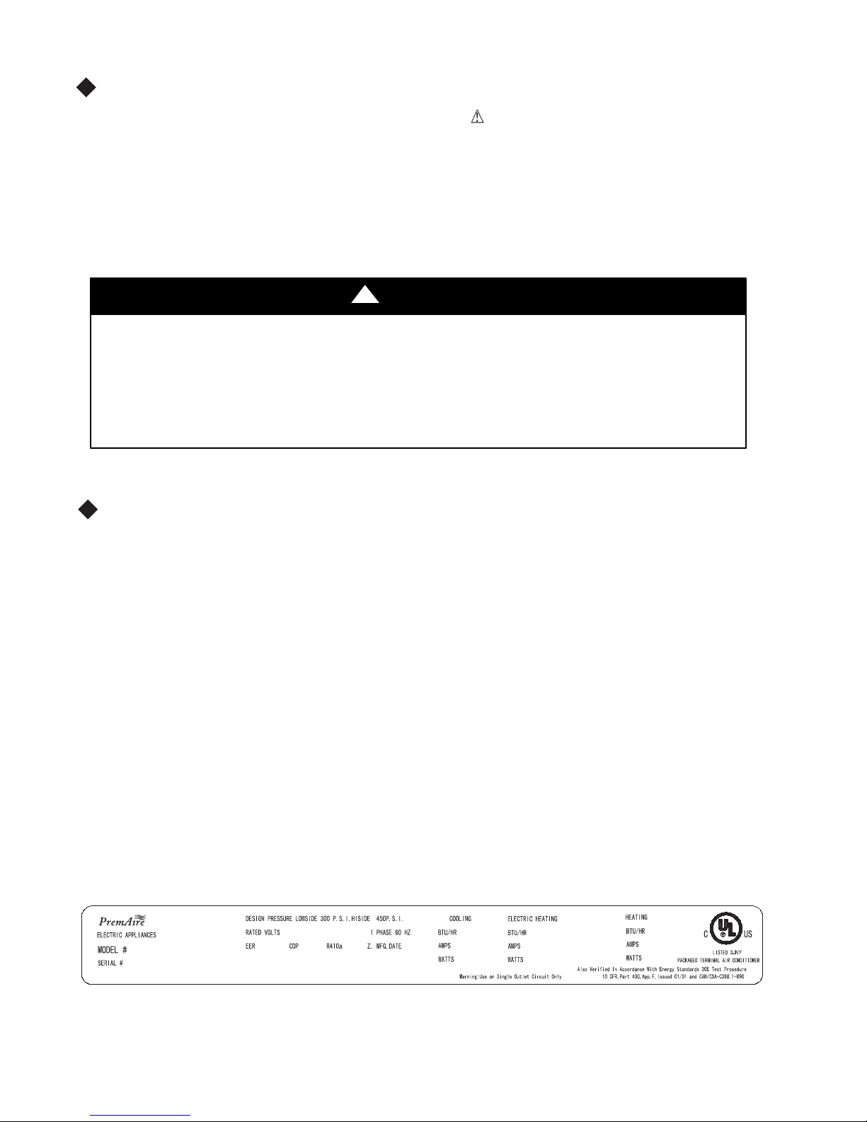
NOTE TO OWNER
Keep these instruct i o ns for fut ure reference. Be sure
space provided on back page. The model and serial
attached to unit. These numbers are required for
pumps
provide a high standard of quality
performance,
in
space year round.
installation. Separate installation instructions are
inspector’s use.
ordinances.
to write down the model and serial number of unit on
number can be located on the serial number plate
service. (See F i g. 1.)
Fig. 1 – Sample Data Information Plate
1
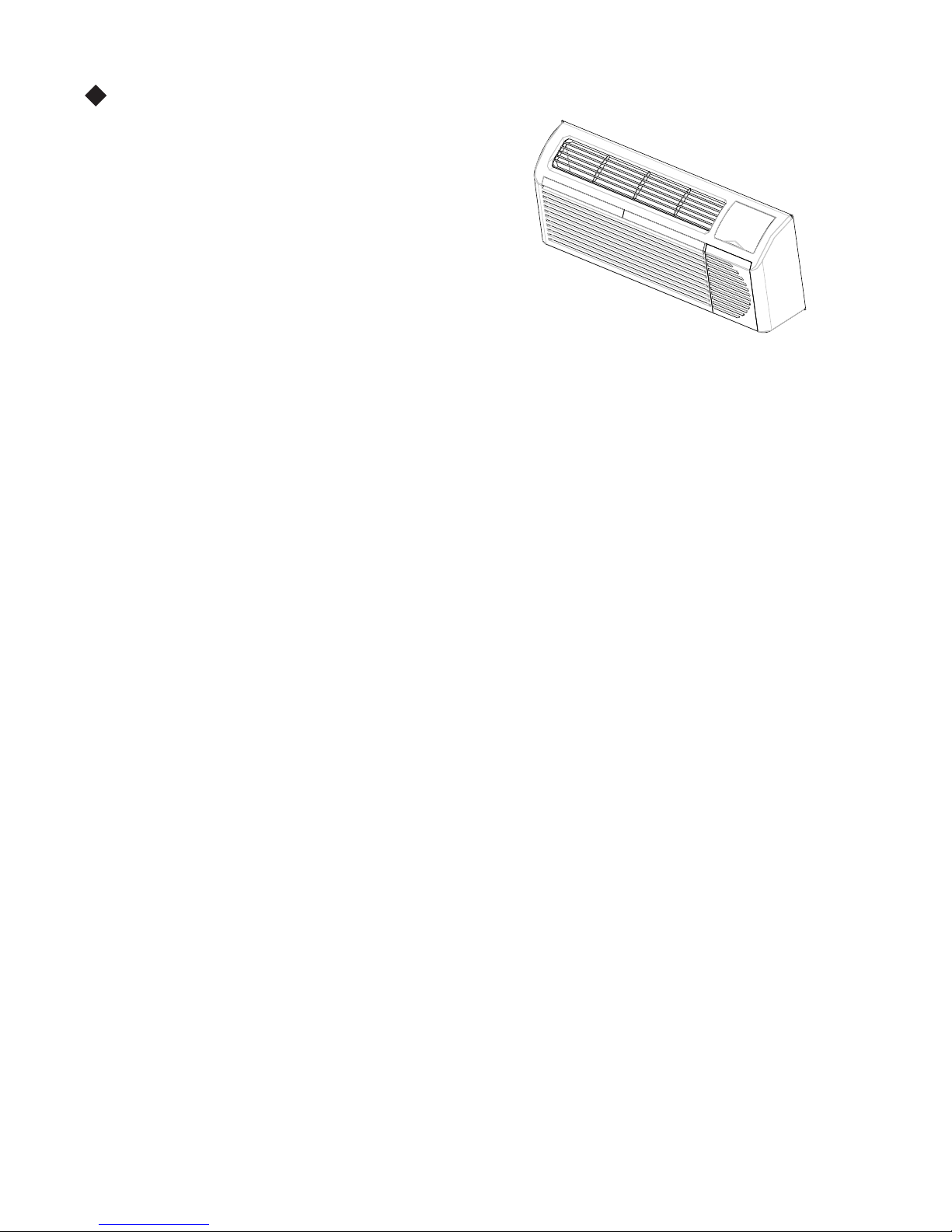
UNIT FEATURES
This Premium Premaire unit has many exciting features which
are different than those found on standard PTAC
models. The owner must be familiar with these
featuresin order to fullyunderstandthe operation and
capability of the unit.
elligence – Your Premium Premaire unit has an on board
•
Int
computerthatutilizesreal timediagnostics to prolong
the life of your unit. There is an LED indicator on the
control board, behind the front panel, that will flash
an error code if the unit has detected some kind of
fault condition. In many cases, the unit will
automatically clear the fault condition and continue
operating with no interruption. In some cases, the
condition cannot be cleared and the unit will require
displayed on the digital display. For a detailed list of
service. In those cases, an “Fx” fai l ure mode wi l l be
all error codes and “Fx” conditions, see Table 6 --
Status LED Indicator Definitions for further details.
Memory – Your Premium Premaire unit also has memory. If power is lost, all of the control settings (setpoint,
•
mode, fan speed, on/off and configuration) are
start back up in the mode (and configuration) it was
• Premium Sound
–
The unit not only does it
optimum sound, the indoor fan will always run a
remembered. So when power is restored, the unit will
in, when power was lost.
have2
fan motors and a tangential blower wheel for
minimum of 10 seconds before the compressor, to
help reduce any compressor starting noise.
• Random Compressor restart -- To help prevent
your PTACs starting at the same time), the
restart delay feature. Whenever the unitis plugged in,
power surges aft er a pow er outage (from man y of
compressor is equipped with a 2:45 to 3:15 random
or power has been restarted, a random compressor
restart will occur.
Compressor Protection -- To prevent short cycling
•
random start--up delay
of 3 minutes on the
compressor and a minimum compressor run time of 3
• Automa tic roo m freeze p rotectio n –automatically
too co l d, where water pi pes migh t freeze. If the unit
active(whichis the default condition), then whenever
temperature below 4 0°F, the fan moto r and electri c
If Freeze protect i on is not requ ired , chan ge the
of the compressor and maximize it’s life, there i s a
will keep the temperature in the room from getting
is config ured for the freeze protection f eatu re to be
power is supplied to the unit, if the unit senses
heater are turned on and will warm the room to 50_F.
configuration switch to turn the feature off (see
section on unit configuration).
Automatic defrost protection (for heat p u mp
•
too cold (approx. 35°F) and the unit can no longer
automaticallyswitchto electricheating. The unit will
temperature rises enough (approx. 40°F), so the
• Automa ti c Q u i ck Warm--up (for h eat pump
below th e set point temperature, the reverse cycle
models only) – When the outdoor temperature gets
effectively heat with the compressor, the unit will
then heat with elect ri c heat unt i l the o ut s i de
compresso r can be used again.
models only) -- If the room temperature falls to 5°F
heat is shut off and the electric strip heat is turned on
for one cycle, until heatin g is satisfied .
LED Indicator’s and Buttons -- The touch pad has
•
SETPOINT UP and SETP OINT DOWN. It also has
setpoint operation, to indicate the unit’s status. The
HEAT, indicate what operating mode is active. The
indicate the fan speed that is selected. The LED
status LED. If the unit i s in ON mode, the LED will
• Configure Fan to Optimize Selected Application
configuring the fan to run in continuous mode or
heater (can be different for bot h heating and cool i ng
compressor or electric h eat er s t op s in order blow off
buttons for MODE, FANS PEED, ON/ OFF,
LEDs that correspond to the mode, fan speed and
LEDs below the mode button, FAN, COOL, and
LEDs below the Fan button, Low, Med and Hi,
located in the lower righ t corner is the un i t On/Off
be green. If the unit is OF F, the LED will be red.
-- Unit can be optimized to selected application by
cycle on and off with the compressor and electric
modes). In cycle mode, fan will continue to run after
any residual heat or cool left on coil.
Fig. 2
minutes.
2

UNIT FEATURES CONTI NUED
• Unit Configuration – Th ere are many different
and the digital keypad, that allow you to configure
unit configuration for more details. Following are the
mentioned:
• _For_C – The unit can display in either _For_C
• Ind oor Temperature Sensor Biasing – Optimize
application(oneforcooling and another for heating)..
• Emergency Heat (for Heat P u mp Only ) – Disable
only with E l ect ri c Heat).
• Display Setpoint OR Roo m Temperature -- T h e
temperature OR setpoint only, during heating and
more details.
• Limit the Setpoint Range -- The unit can be
display will always show the complete setpointrange,
configuredminimum andmaximumsetpointselected.
• Energy Management – Sometimes known as
unit can be manually disabled from a different
automatically turn itself off. If no voltage is detected
• Wall Thermostat Control –Awiredwall
unit must be configured to disable the keypad. S ee
more details.
configurationpossibilities, through both dipswitches
the unit for your exact application. See section on
configuration selections thathavenot previously been
the room temperature sensor reading to your exact
the compressor during heating m ode operation (heat
unit can be configured to display the room
cooling modes. See section on unit configuration for
configuredtolimitthe controllingsetpointrange.The
but the controlling setpoint will be limited t o the
See section on unit configuration for more details.
Front Desk Control, an input is provided so that the
location. If the unit detects 24vac on this input, it will
on the input, the unit will run normally.
thermostat can be connected to the unit. If it is, the
section on wired inputs and unit configuration for
3
ELECTRICAL DATA
!
ELECTRICAL SHOCK HAZARD
Failure to follow this warning could result in personal
DO NOT alter cord or plug or use an extension cord.
POWER CONNECTION OPTIONS
Appropriate power cord accesso ry kit is determin ed
The unit d o es not come with a power cord (or
be ordered to connect the unit to the outlet. If the
must be ordered.
IMPORTANT: For 265V units, if power cord
long and must plug into the accessory electrical
Be sure that youroutlet matches the appropriate blade
the serv i ce cord.
All wi ri ng , includ i ng inst al l at i on of t h e receptacle,
ordinances and regulations. National codes require
device on all208/230V power cords. Be sure toselect
ALL UNITS
Wire Size
Use recommended wire size given in Table1 and
with local and national codes. All units are
NOTE: Use copper conductors only.
Table 1—SUGGESTED BRANCH CIRCUIT WIRE SIZES*
NAMEPLATE AMPS
7.0 to 12 14
12.1 to 16 12
16.1 to 24 10
Grounding
For safety and protection, the unit is grounded
wire provided on hard wired units. Be sure
VOLTAGE SUPPLY
Check voltage supply at outlet. For satisfactory
ranges found on the data i nformation plate.
Cord--connected
The 250--v field supplied outlet must match the plug
of the serv i ce cord. The standard cord--co nn ect ed
for operat i on . Refer to Table 2 for prop er receptacle
Power Cord
The power cord for 230/208v units provide power
disconnects when unsafe conditions are detected.
buttononplughead.
Upon completion of unit installation for 230/208V
using the TEST/R ESET buttons on the plug head.
NOTE: The 265v models do not incorporate this
Units
Protection
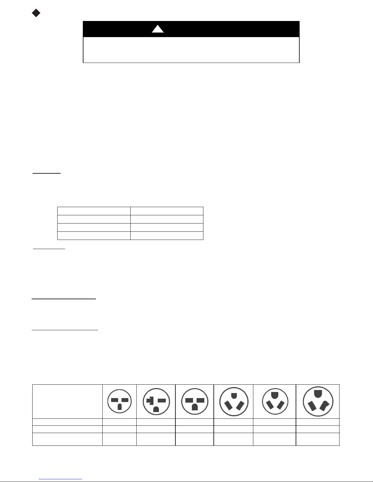
Table 2—RECEPTACLES AND FUSE TYPES -- 250, 265 VOLTS
design ed to opera te off ONE single b ranchcircuits
AWG WIRE SIZE{
through the service cord plug or through separate
that the branch circuit or general purpose outlet is
feature as they require use of the electrical subbase
WARNING
injury or death and/or property damage
by the voltage, and amperage of the branch circuit.
hard wire kit). An acces s ory po wer cord kit must
unit is to be hard wired, an accessory hard wire kit
accessory option is selected, the cord is only 18”
265V subbase.
configurat i o n of the pl u g and that it is wit hi n reach of
must be in accordance with t h e NEC and local codes,
the use of an arc fault or leakage current detecti on
the correct cord for your installation.
install a single branch circuit. All wiring must
LEGEND
AW G --- A me r i ca n W ire G a u ge
* Single circuit from main box.
{ Based on copper wire at 60_C temperature rating.
results, the voltage range must always be within the
for the standard 208/230--v units and be withi n reach
265--v units requi re an access o ry electrical s ubbase
and fuse type.
cord fire protection.
Unit power automatically
Power to the unit can be restored by pressing thereset
models, an operational check should be performed
comply
only.
grounded.
ground
accessory.
RECEPTACLE
AMPS 15 20 30 15 20 30
RATED VOLTS 250 250 250 265 265 265
T I M E --- D E L A Y T Y P E F U SE
(or HACR Circuit Breaker)
LEGEND
HACR - -- Heating, Air Conditioning, Refrigeration
* May be used fro 15 --- amp applications
15 20* 30 15 20 30
4
 Loading...