

Page 1
LED Driver PR4401 / PR4402
0.9 V Boost Driver for White LEDs
Requires Only One External Component
The PR4401 and PR4402* are single cell step-up
converters for white LEDs operating from a
supply voltage of less than 0.9 V. Only one
external inductor is needed for operation of a
white LED. PR4401 is recommended for mean
LED currents of up to 20 mA, PR4402 for up to
40 mA. This makes PR4401 and PR4402 ideal for
use in low-cost or small-sized applications such
as LED flashlights or LCD backlighting for
portable devices.
FEATURES
• minimum startup voltage 0.9 V
• 200 / 250 mA peak output current
• only one external component required
• battery deep discharge protection
APPLICATIONS
• Small-sized LED torches
• LCD backlighting
• LED indicator lights
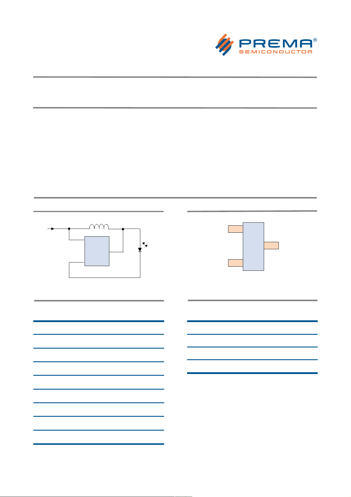
TYPICAL APPLICATION
For output currents higher than 20 mA an additional
blocking capacitor at Vcc is recommended.
PIN DESCRIPTION
Topside marking: "UI" (PR4401) or "UJ" (PR4402) with
a two-digit lot code Package SOT23-3 or COB on
request
The inductance L1 determines the LED current:
Inductance L1 Mean current For
47 µH 6.5 mA PR4401
32 µH 8.3 mA PR4401
26.7 µH 10.8 mA PR4401
22 µH 11 mA PR4401
14.7 µH 14 mA PR4401
10 µH 22 mA PR4401/4402
6.8 µH * 32 mA * PR4402
4.7 µH * 40 mA * PR4402
PIN Description:
PIN Name PIN Function Description
Vcc Supply voltage
Vout Output voltage, LED connection
Gnd Ground connection
* PR4402 only measured with inductor
Murata type LQH32C series
10 - 22 µH: one white LED
4.7 - 6.8 µH: two white LEDs in parallel
© PREMA Semiconductor GmbH 2006-2014 I rev. 1014 Page 1/12
Vcc
Gnd
Vout
PR4401/02
Vbat =1.2 V or 1.5 V
L1
White
LED
Vcc
Vout
Gnd
top view
U
I
x
x
Page 2
LED Driver PR4401 / PR4402
Electrical Properties
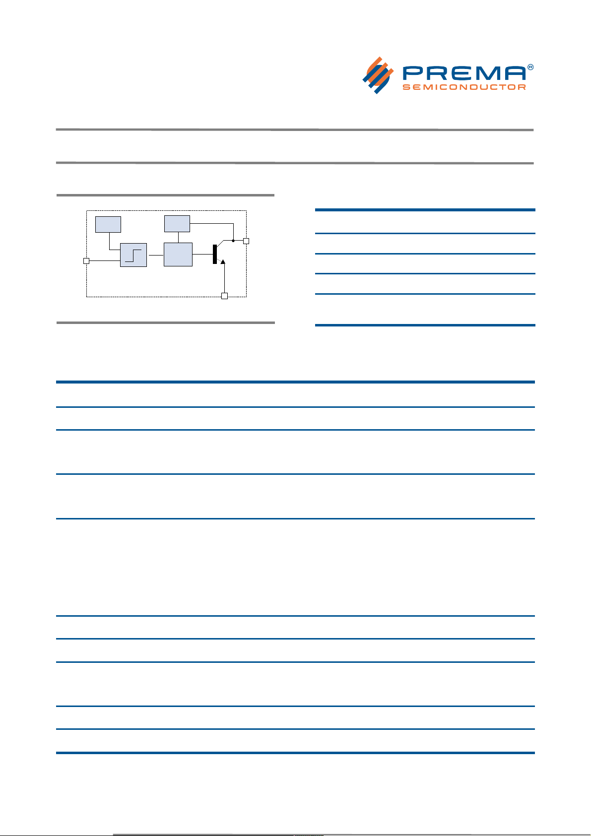
BLOCK DIAGRAM
ABSOLUTE MAXIMUM RATNGS
(PR4401 and PR4402)
Parameter Units Min Max
Vcc (no damage) [V] -0.3 8
Operating Temperature Range [°C] -20 85
Storage Temperature Range [°C] -55 150
Electrostatic Discharge (ESD)
Protection
[kV] 2 -
ELECTRICAL CHARACTERISTICS
Vcc = 1.5 V, Ta = 25°C, 10 - 22 µH: one white LED / 4.7 - 6.8 µH: two white LEDs in parallel, unless otherwise noted.
PR4401 PR4402
Parameter Conditions Units Min Typ Max Min Typ Max
Supply Voltage, min. operating
min. startup
max. operating
L1 = 10...22 µH
Ta = 25°C
[V]
[V]
[V] 1.90
0.70
0.90
0.80
0.95
1.90
0.70
0.90
0.80
0.95
Supply Voltage, min. operating
min. startup
max. operating
L1 = 10...22 µH
Ta = 0...60°C
[V]
[V]
[V] 1.90
0.80
1.00
0.90
1.05
1.90
0.80
1.00
0.90
1.05
LED Mean Current
measured with L1 type
LQH32C Murata
L1 = 47 µH
L1 = 32 µH
L1 = 26.7 µH
L1 = 22 µH
L1 = 14.7 µH
L1 = 10 µH
L1 = 6.8 µH
L1 = 4.7 µH
[mA]
[mA]
[mA]
[mA]
[mA]
[mA]
[mA]
[mA]
6.5
8.3
10.8
12
15
23
--
--
--
--
-12
15
23
32
40
Switching Current at Vout Vout = 0.4 V [mA] 200 250
Switching Frequency [kHz] 500 500
Quiescent supply current Vcc > 950 mV
Vcc = 600 mV
Vcc = 400 mV
[mA]
[µA]
[µA]
4
50
10
5 8
100
20
10
Efficiency [%] 80 80
Vout [V] Vcc 15 15
© PREMA Semiconductor GmbH 2006-2014 I rev. 1014 Page 2/12
Vcc
Ref.
Comp.
Vout
Control
Logic
Gnd
Page 3
LED Driver PR4401 / PR4402
Typical Characteristics
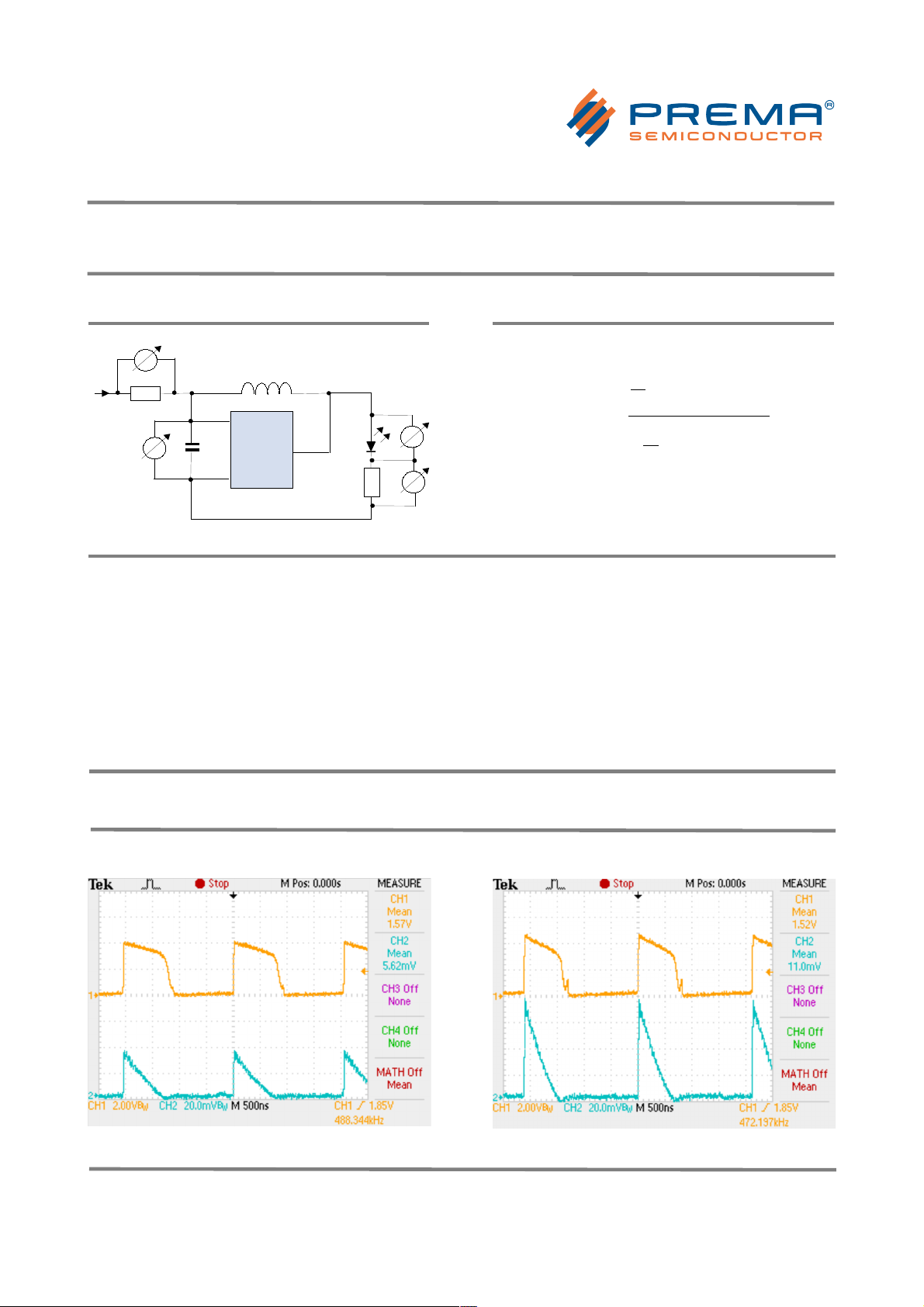
TEST CIRCUIT
MEASUREMENT + CALCULATION OF EFFICIENCY
Efficiency [% ]=
1
T
∫
0
T
(
V
LED⋅ILED
)
dt
1
T
∫
0
T
(
Vin⋅I
in
)
dt
⋅100
Depending on test setup and measuring
method, efficiency values can vary by approx.
±5 %, and peak current values can vary by up
to ±20 %, Accuracy of mean currents: ±1 mA.
Measuring conditions for all diagrams, unless
otherwise noted:
• Ta = 25°C
• one LED connected (peak voltage 4.2...5.8 V)
A LQH32C from Murata has been used as
reference inductor, the DC resistance is
specified as
• 0.44 Ω ± 30 % for 10 µH
(max current 300 mA)
• 0.71 Ω ± 30 % for 22 µH
(max. current 250 mA)
• 1.30 Ω ± 30 % for a 47 µH inductor
(max. current 170 mA).
OSCILLOSCOPE DISPLAYS
PR4401; LED voltage (CH1) and LED current (CH2, over 0.5 Ω resistor)
with L1 = 22 µH
with L1 = 10 µH
© PREMA Semiconductor GmbH 2006-2014 I rev. 1014 Page 3/12
L1
0.5 Ω
or 1Ω
470 nF
Vcc
Gnd
PR4401
Vout
0.5 Ω
or 1Ω
Page 4
LED Driver PR4401 / PR4402
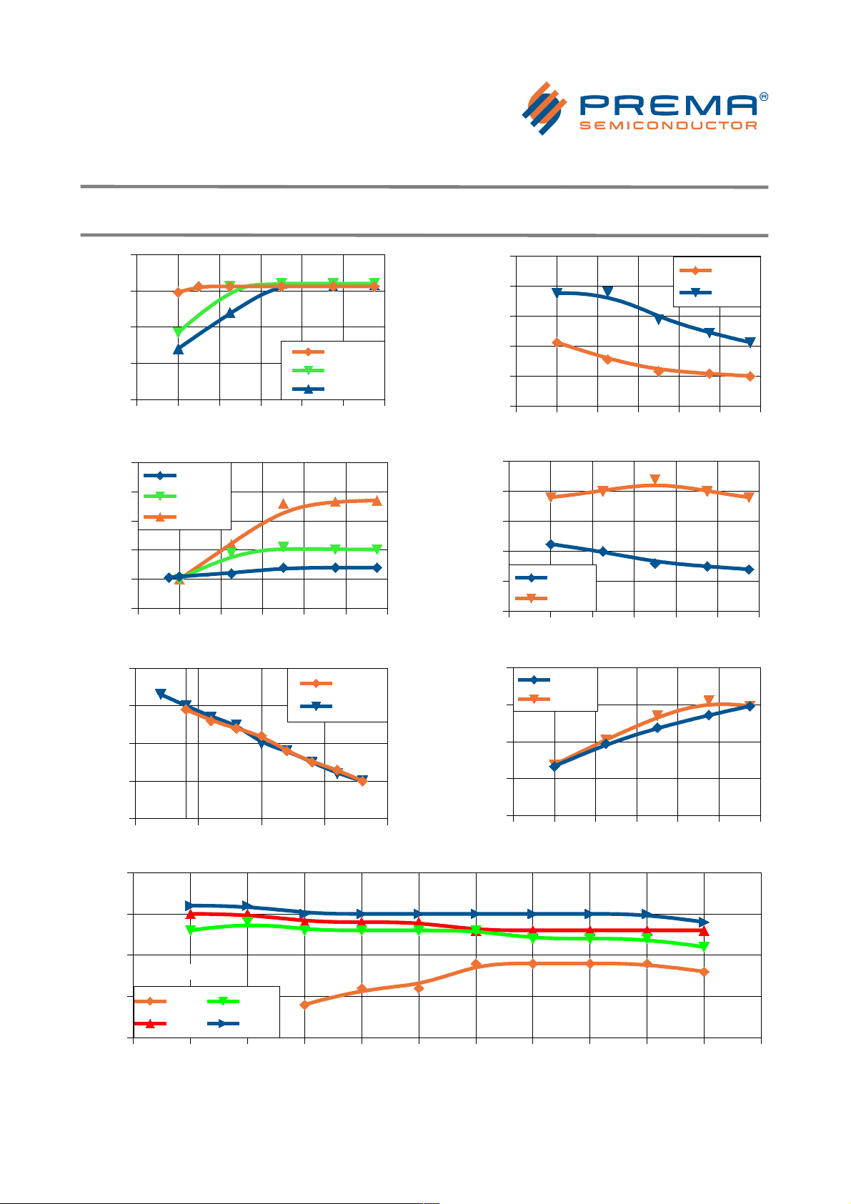
Characteristic Performance Curves for PR4401
0,8 1 1,2 1,4 1,6 1,8 2
0
25
50
75
100
22 µH
14.7 µH
10 µH
Supply Voltage [ V ]
Efficiency [%]
0,8 1 1,2 1,4 1,6 1,8 2
5
10
15
20
25
30
22 µH
14.7 µH
10 µH
Supply Voltage [V]
LED Mean Current [mA]
-20 5 30 55 80
0,7
0,8
0,9
1
1,1
22 µH
10 µH
Temperature [°C]
Startup Voltage [V]
0,8 1 1,2 1,4 1,6 1,8 2
0
25
50
75
100
125
22 µH
10 µH
Supply Voltage [V]
Supply Current [mA]
0,8 1 1,2 1,4 1,6 1,8 2
0
50
100
150
200
250
22 µH
10 µH
Supply Voltage [V]
LED Peak Current [mA]
0,8 1 1,2 1,4 1,6 1,8 2
0
200
400
600
800
22 µH
10 µH
Supply Voltage [V]
Frequency [kHz]
-30 -20 -10 0 10 20 30 40 50 60 70 80
10
15
20
25
30
1.00 V 1.25 V
1.50 V 1.75 V
Temperature [°C]
Mean LED current [mA]
L1 = 10 µH
© PREMA Semiconductor GmbH 2006-2014 I rev. 1014 Page 4/12
Page 5
LED Driver PR4401 / PR4402
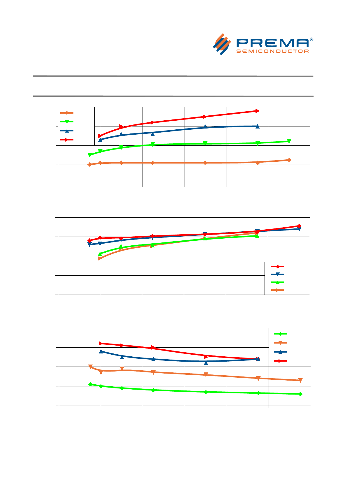
Characteristic Performance Curves for PR4402
0,8 1 1,2 1,4 1,6 1,8 2
0
10
20
30
40
22 µH
10 µH
6.8 µH
4.7 µH
Supply Voltage [V]
LED Mean Current [mA]
0,8 1 1,2 1,4 1,6 1,8 2
0
25
50
75
100
22 µH
10 µH
6.8 µH
4.7 µH
Supply Voltage [V]
Efficiency [%]
0,8 1 1,2 1,4 1,6 1,8 2
0
100
200
300
400
22 µH
10 µH
6.8 µH
4.7 µH
Supply Voltage [V]
LED Peak Current [mA]
© PREMA Semiconductor GmbH 2006-2014 I rev. 1014 Page 5/12
Page 6

LED Driver PR4401 / PR4402
Application Notes
INFLUENCE OF THE LED FORWARD VOLATAGE
(measured with 1 LED / 2 LEDs in parallel; Vcc = 1.5 V)
Circuit
LED Peak
Forward
Voltage
LED
Mean
Current
Mean
Supply
Current
Efficiency
10 µH
1 LED
5.8 V 20 mA 70 mA 77 %
10 µH
2 LEDs ||
4.6 V 24 mA 70 mA 80 %
22 µH
1 LED
4.2 V 13 mA 33 mA 82 %
22 µH
2 LEDs ||
3.5 V 14 mA 32 mA 82 %
SELECTION OF PR4401 AND PR4402
The circuit type should be selected according to
the required LED current:
• PR4401 is best operated with inductors
between 10 and 22 µH.
• PR4402 is best operated with inductors
between 4.7 and 10 µH.
Using lower inductances may lead to erratic
behaviour, especially at low supply voltages
and should be avoided.
Operating with higher inductances is possible
and will lead to lower supply and LED currents.
However the quiescent current which is
independent of the inductance will lead to a
lower overall efficiency. Since PR4402 has about
twice the quiescent current of PR4401, it is not
recommended for small LED currents.
LED COMPATIBILITY
It must be considered that the peak current
through the LED is a factor of up to 7 higher
than the mean current. LED lifetime may be
affected if operated outside the range specified
by the LED vendor. Since the emission spectrum
of white LEDs usually depends on the current,
the light color may shift to blueish white. High
peak currents may also saturate the LED and
reduce the light efficiency of the LED. If the
rated LED peak current is exceeded, it is
recommended to use a smoothing capacitor
and diode to provide a continuous output
current (see below). With most standard LEDs,
this will improve the overall performance with
inductors of 10 µH and less, or mean output
currents of 23 mA and more.
Note that with especially with the higher
currents of PR4402 the current rating of most
standard LEDs is exceeded, and more powerful
or multiple LEDs must be used.
INDUCTUR COMPATIBILITY
While the series resistance of the coil has a
small impact on the LED current, it is important
that the saturation current is higher than the
maximum peak current over the supply voltage
range. Inductors optimized for DC-DC converters
are mostly suitable.
CONNECTION FROM BATTERY
Due to high peak currents, it is important to
connect the PR4401/PR4402 to the battery with
short, low resistance wires, to achieve the best
performance. A voltage drop along the wire
affects LED current, efficiency and minimum
startup and operating voltage. This is most
critical for applications with low inductivity and
high current. In cases where a longer wire from
the battery cannot be avoided, a capacitor
should be placed close to the Vcc and Gnd pin of
PR4401. Typically capacitors between 220 nF
and 1 µF are used. With PR4402 operated at
higher currents, a blocking capacitor is usually
necessary even if wires or board layout are
optimized.
© PREMA Semiconductor GmbH 2006-2014 I rev. 1014 Page 6/12
Page 7
LED Driver PR4401 / PR4402
Application Notes
TYPICAL BATTERY LIFE TIME
Battery
Lifetime
L1 = 22 µH
LED mean
current 12 mA
Battery
L1 = 10 µH
LED mean
current 23 mA
AA (Mignon,
LR 6/AM-3)
55 h 27 h
AAA (Micro,
LR 03/AM-4)
22 h 8 h
Conditions: one white LED connected, measured with
single 1.5 V TDK Alkaline battery.
Battery lifetime depends on battery capacity and
operating conditions. Therefore the times indicated
here can only give a rough indication of achievable
times.
USING DIFFERENT BATTERY TYPES
The input voltage must be 1.9 V at maximum. At
higher voltages the circuit may not trigger and
start up correctly. Therefore operation with one
Alkaline, NiCd, or NiMH cell (AA or AAA type) is
recommended.
Alkaline button cells can also be used for
supply. However, since high peak currents are
drawn from the battery, button cells are
recommended only with inductors of 22 µH or
more, depending on the battery type. A
capacitor at the supply pins of PR4401 may also
improve performance with button cells.
Lithium batteries are not suitable due to their
higher voltage.
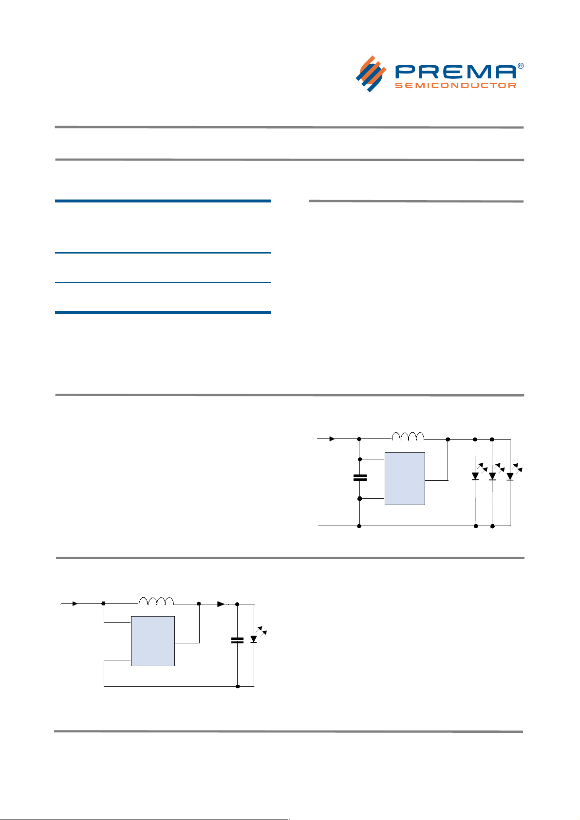
CONNECTING SEVERAL LEDs IN PARALLEL
When several LEDs are connected in parallel, it
is necessary to match the forward voltage of
these LEDs, to achieve a uniform brightness.
The total current of all LEDs together
corresponds approximately to the mean output
current for operation with one LED.
Vcc
Gnd
Vout
PR4402
Vbat = 1.2 V
or 1.5 V
L1 = 4.7 µH
Matching
White LEDs
470 nF
Vcc
Gnd
Vout
PR4401/02
Vbat = 1.2 V
or 1.5 V
L1
White
LED
S
OPERATION OF LEDs WITH SMOOTHED CURRENT
(RECTIFIER)
With a diode (preferably a Schottky diode) and a
smoothing capacitor the voltage at the LED can
be buffered if necessary. The capacitance must
be small enough so that the voltage at the
capacitor will exceed a voltage of 2.5 V in the
first cycle, otherwise the circuit may not start
up. In most cases, values between 100 nF and
1 µF are appropriate. Due to different load
characteristics, output current and efficiency
are typically higher than without capacitor,
especially in the high-current range.
© PREMA Semiconductor GmbH 2006-2014 I rev. 1014 Page 7/12
Page 8
LED Driver PR4401 / PR4402
Application Notes
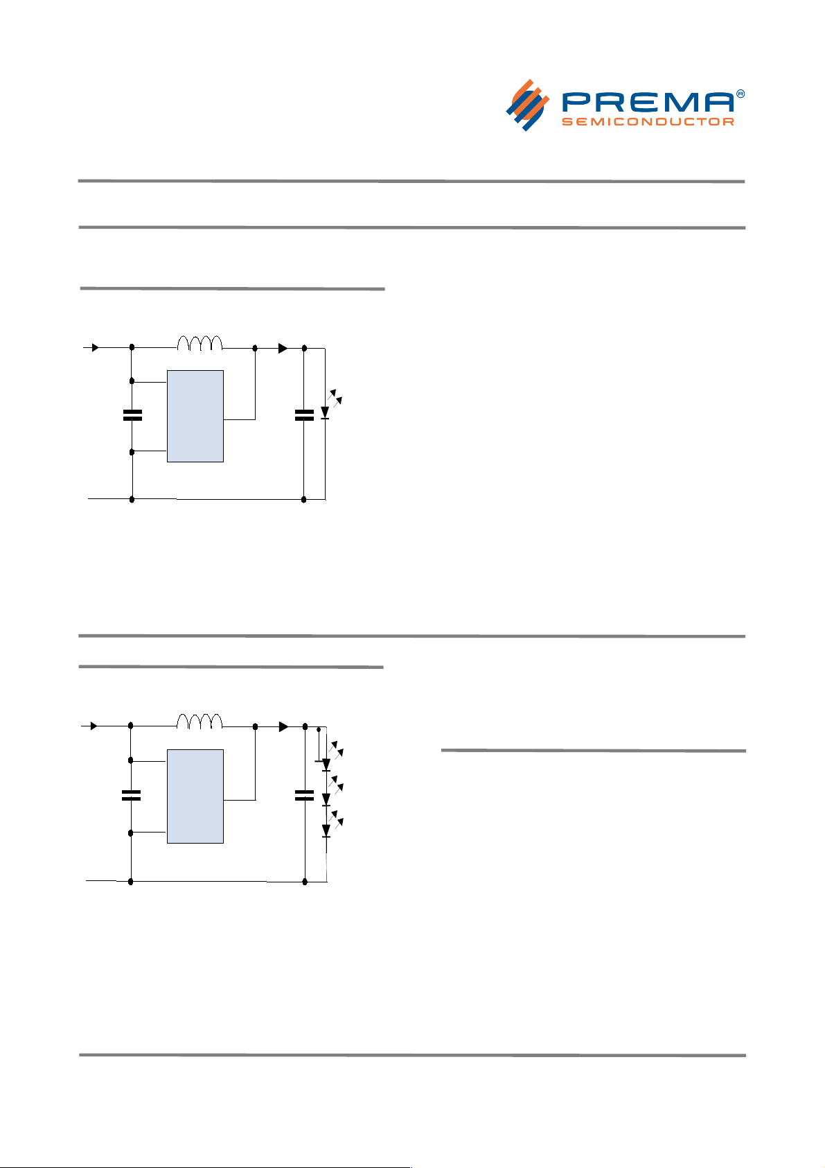
RECOMMENDED CONFIGURATION FOR HIGHER
LEDs CURRENTS
While for lower LED currents it is possible to
operate PR4401 with the minimum number of
components, it is recommended to provide both
rectifier circuit at the output and buffer
capacitor at the input at high LED currents, to
achieve the best performance.
Whether the extra components are necessary
or not depends largely on the performance of
the components used, most importantly the
peak current of the LED, the internal resistance
of the battery and the resistance of the battery
cables. If by adding the extra components the
mean LED current increases significantly, it is
usually advisable to add them permanently to
achieve a high efficiency.
As a rule of thumb, with a 22 µH inductor the
extra components will usually not increase the
current significantly, while for inductors below
10 µH they will usually improve the performance
noticeably.
Buffer capacitor and rectifier circuit are
independent measures. For powerful LEDs, or
two or more LEDs in parallel at the output, the
rectifier may not be necessary, but the buffer
capacitor will still prevent high voltage drops
along the supply wire.
For the buffer capacitor, values between 220 nF
and 1 µF are common.
CONNECTING TWO LEDs IN SERIES
Vcc
Gnd
Vout
PR4401/02
Vbat = 1.2 V
or 1.5 V
L1
White
LED
S
470 nF
470 nF
It is possible to operate PR4401 and PR4402
with two LEDs in series at the output.
However, while the peak output current is
nearly independent of the output load, the
mean output current with two LEDs in series is
reduced to half the current with one LED. In
addition, at high output voltages the efficiency
drops significantly, depending on operating
conditions, and current pulses become shorter
and sharper. Therefore it is recommended to
operate LEDs in this mode only in conjunction
with the rectifier circuit as shown below.
USING RED, GREEN OR YELLOW LEDs
Although PR4401/PR4402 is optimized for
operation with white or blue LEDs, it will usually
also work with red, green or yellow LEDs, with
the following restrictions:
a) The LED must build up a sufficient forward
voltage to trigger PR4401/PR4402. Due to the
internal resistance of the LED, this condition
is usually met. However, no guarantee can
be assumed for proper operation under all
conditions, and you need to qualify the
system yourself.
b) Due to the different forward voltage level and
internal resistance of coloured LEDs, the
timing is different, and mean currents are
mostly lower than for white LEDs. Also other
parameters may deviate from this data
sheet.
© PREMA Semiconductor GmbH 2006-2014 I rev. 1014 Page 8/12
Vbat = 1.2 V
or 1.5 V
L1
S
Vcc
470 nF
Vout
Gnd
PR4401/02
White
LED
Page 9
LED Driver PR4401 / PR4402
Installation Notes
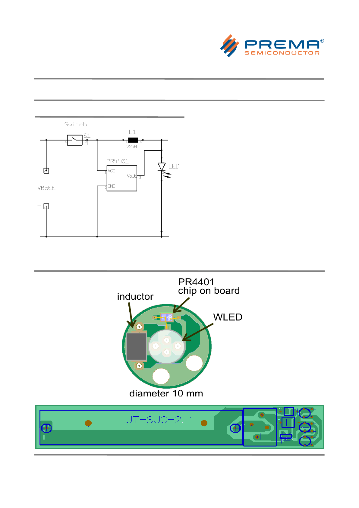
SAMPLE BOARD LAYOUT
FLASHLIGHT BOARD WITH AAA BATTERY HOLDER
Size: 77.5 mm x 14 mm
© PREMA Semiconductor GmbH 2006-2014 I rev. 1014 Page 9/12
Page 10
LED Driver PR4401 / PR4402
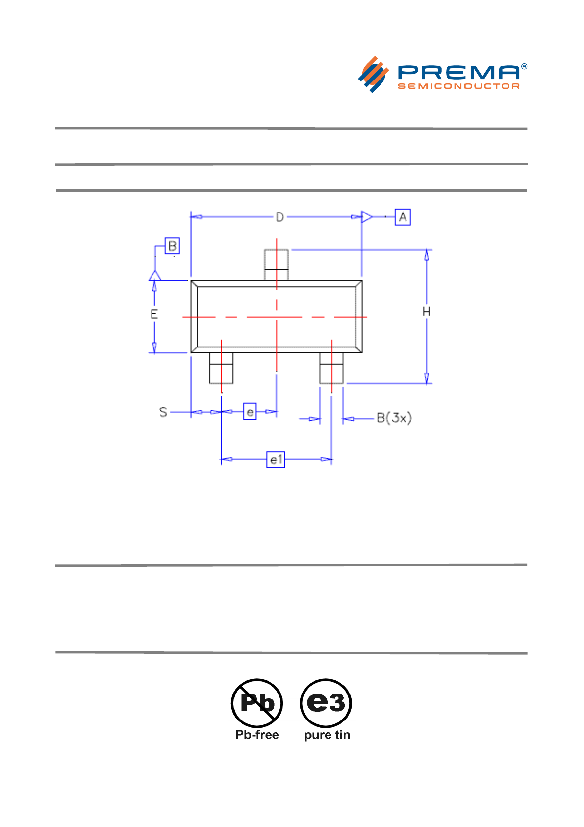
Available Packages
TYPICAL DIMENSIONS
B = 0.40 mm
D = 2.92 mm
E = 1.30 mm
H = 2.37 mm
e1 = 1.92 mm
PR4401/PR4402 SOT23 package in tape and reel
Packing unit: 3000 ICs per reel
(reel diameter 7" / 178mm)
Delivery in die form on request.
All parts delivered comply with RoHS. Finish is pure tin.
© PREMA Semiconductor GmbH 2006-2014 I rev. 1014 Page 10/12
Page 11

LED Driver PR4401 / PR4402
© PREMA Semiconductor GmbH 2006-2014 I rev. 1014 Page 11/12
Page 12

LED Driver PR4401 / PR4402
Disclaimer
Information provided by PREMA is believed to be accurate and correct. However, no responsibility is assumed by
PREMA for its use, nor for any infringements of patents or other rights of third parties which may result from its use.
PREMA reserves the right at any time without notice to change circuitry and specifications.
Life Support Policy
PREMA Semiconductors products are not authorized for use as critical components in life support devices or
systems without the express written approval of PREMA Semiconductor. As used herein:
1. Life support devices or systems are devices or systems which, (a) are intended for surgical implant into the body,
or (b) support or sustain life, and whose failure to perform when properly used in accordance with instructions for
use provided in the labeling, can be reasonably expected to result in a significant injury to the user.
2. A critical component is any component of a life support device or system whose failure to perform can be
reasonably expected to cause the failure of the life support device or system, or to affect its safety or effectiveness.
PREMA Semiconductor GmbH
Robert-Bosch-Str. 6
55129 Mainz Germany
Phone: +49-6131-5062-0
Fax: +49-6131-5062-220
Email: [email protected] Web site: www.prema.com
© PREMA Semiconductor GmbH 2006-2014 I rev. 1014 Page 12/12
 Loading...