

Prema DMM 5017 SC, DMM 5017 User Manual
_____________________________________________________________________________________________________________________________________
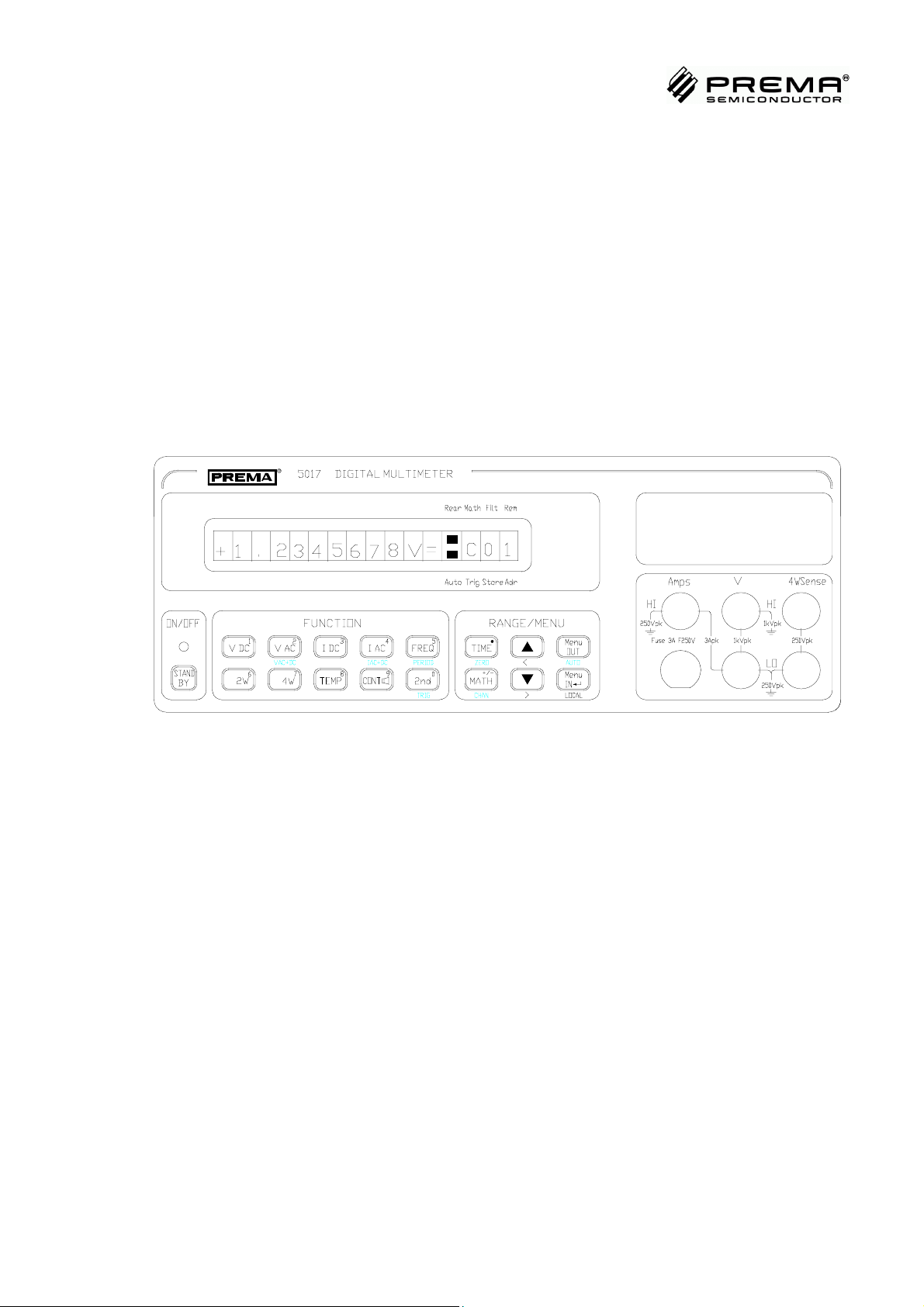
DIGITAL MULTIMETER 5017
7 ½ Digit Precision Multimeter with IEEE-488 and RS232 Interface
DMM 5017 / DMM 5017 SC
User´s Manual
PREMA Semiconductor GmbH
•
Robert-Bosch-Str. 6
Tel. +49-6131-5062-20
E-Mail: instruments @ prema.com
Internet: http: / / www.prema.com
D-55129 Mainz • Germany
•
Fax. +49-6131-5062-22
Subject to change without notice
AS5017-0045

_____________________________________________________________________________________________________________________________________
Table of Contents
Table of Contents
TABLE OF CONTENTS 1
1 INTRODUCTION 1-1
1.1 Features 1-1
1.2 Various Versions 1-1
1.3 Important Safety Instructions 1-2
Reading the User Manual 1-2
Further Safety Instructions 1-2
Predictability of Dangers 1-3
Proprietary Rights 1-3
Conformity Declaration 1-3
Proper Utilization as intended 1-3
Availability of the User Manual 1-5
2 GETTING STARTED 2-1
2.1 Delivery 2-1
2.2 Safety Guidelines 2-2
Utilization 2-2
2.3 Safety Symbols 2-3
2.4 Accident Prevention 2-3
2.5 Connecting the Unit to Main Power 2-3
2.6 Grounding 2-4
2.7 Warranty 2-5
2.8 Certificate 2-5
2.9 Turning it on 2-5
2.10 Connection of Measurement Leads 2-6
Operation with rear panel inputs and Scanner 2-8
2.11 Rack Mounting 2-8
2.12 Miscellaneous 2-9
Conforming to the Norm EN 61010 2-9
Scanner with Model 5017SC 2-9
3 QUICK START 3-1
3.1 Default Settings 3-1
3.2 Scanner (5017SC) 3-1
3.3 Measuring Voltage 3-2
3.4 Measuring Current 3-3
1

Table of Contents
_____________________________________________________________________________________________________________________________________
3.5 Measuring Resistance 3-4
3.6 Measuring Temperature 3-5
3.7 Frequency and Period Measurement 3-6
3.8 Continuity Test 3-7
3.9 Selecting Measurement Ranges 3-7
3.10 Setting the Integration Time / Resolution 3-8
3.11 Display 3-9
Display with Settings 3-9
Meaning of the Settings 3-9
Display with Mathematics 3-10
Display with Channel 3-10
Display with Time Counter 3-11
4 MANUAL OPERATION 4-1
4.1 Keypad 4-1
The Function Field 4-2
The Range / Menu Field 4-3
4.2 The Display Field 4-4
Display Elements 4-4
4.3 Measuring Inputs 4-5
Connecting the Measuring Cables 4-5
Limiting Data for the Measuring Inputs 4-6
4.4 Setting the Measuring Functions 4-7
4.5 Measuring Range Selection 4-7
4.6 Channel Selection for 5017SC 4-8
4.7 Offset Correction 4-8
4.8 Navigating in the Menu Structure 4-9
4.9 Mathematical Programs 4-11
Selection / Manual Control 4-11
Meaning of the Mathematical Programs 4-12
4.10 The Menu "Configure" 4-13
Start Mode / Trigger Mode 4-13
Filter 4-13
Automatic Filter (Auto Filter) 4-14
Fast Automatic Filter (Fast Auto Filter) 4-14
Moving Average Filter (Avg. Filter) 4-14
Filter Selection 4-15
Saving and Loading Instrument Settings 4-15
Power-Up Status 4-16
Calibration 4-16
4.11 The Menu "Device" 4-17
Setting the Contrast 4-17
Preselecting the Interface 4-18
2

_____________________________________________________________________________________________________________________________________
Table of Contents
Preselecting the Command Set for Remote Control 4-19
Selecting the Temperature Sensor 4-20
Activating the Loudspeaker 4-21
Setting the Display Formats 4-21
Setting the Scanner Mode 4-23
4.12 Error Messages 4-24
5 REMOTE CONTROL 5-1
5.1 Configuration 5-1
Select Interface 5-1
Configuring the RS232 Interface 5-1
Configuring the IEEE-488 Interface 5-2
Define the Command Set 5-2
5.2 General Information concerning Remote Control 5-3
5.3 Special Features for the RS232 Interface 5-3
5.4 Capabilities of the IEEE-488 Bus Interface 5-4
General IEEE-488.1 Messages 5-4
5.5 RS232 / IEEE-488.2 Common Commands 5-5
*CLS, Clear Status Command 5-5
*ESE Standard Event Status Enable Command 5-6
*ESE? Standard Event Status Enable Query 5-6
*ESR? Standard Event Status Register Query 5-6
*IDN? Identification Query 5-7
*OPC Operation Completed Command 5-7
*OPC? Operation Completed Query 5-7
*RST Reset Command 5-7
*SRE Service Request Enable Command 5-8
*SRE? Service Request Enable Query 5-8
*STB? Read Status Byte Query 5-8
*TST? Self Test Query 5-9
*WAI Wait-to-Continue Command 5-9
5.6 Structure of the Registers 5-10
5.7 Operation as Listener 5-11
5.8 Display Mode 5-14
5.9 String Length Selection 5-16
5.10 SRQ Mode 5-16
5.11 Operation of the Digital Multimeter as TALKER 5-16
Description of the Message Record Sent 5-17
Table of Device Messages sent by the Multimeter 5-18
Meaning of the Transmitted Characters 5-19
5.12 Error Messages 5-21
5.13 Compatibility 5-23
5017 as Listener 5-23
3

Table of Contents
_____________________________________________________________________________________________________________________________________
5017 as Talker 5-25
Difference between 5017 and 6001 concerning hardware 5-27
6 CALIBRATION 6-1
6.1 Calibration Periods 6-1
6.2 PREMA Calibration Service 6-1
6.3 Necessary Equipment 6-1
6.4 Automated Calibration 6-2
6.5 Important Steps prior to Calibration 6-3
6.6 PIN Number and Calibration Switch 6-4
Changing the PIN Number 6-5
6.7 Offset Correction 6-6
6.8 Calibrating DC Voltage 6-7
Offset Correction for DC Voltage 6-7
Calibration of DC Voltage 6-7
6.9 Calibration of Resistance Ranges 6-8
Offset Correction 6-8
Calibration of Resistance 6-8
6.10 Calibration of AC Voltage 6-9
6.11 Calibration of DC and AC Current 6-9
6.12 Calibration of Temperature 6-9
6.13 Storing Calibration Values 6-11
7 OPERATING INSTRUCTIONS 7-1
7.1 DC Voltage Measurement 7-1
Input Resistance in DC Voltage 7-1
Series Mode Suppression 7-2
Common Mode Suppression 7-3
Thermal Voltages 7-3
Noise Effects Through Inductive Interferences 7-4
7.2 Resistance Measurement 7-5
Two-Wire Resistance Measurement 7-5
Four-Wire Resistance Measurement 7-7
Power Dissipation in the Resistors 7-8
7.3 AC Voltage Measurement 7-8
7.4 DC and AC Current 7-9
7.5 Temperature Measurement 7-10
8 CONSTRUCTION 8-1
8.1 Input Circuit 8-1
8.2 Integrating A to D Converter 8-2
Mains Synchronization 8-3
4

_____________________________________________________________________________________________________________________________________
Table of Contents
Reference 8-4
8.3 Measurement of AC Voltage 8-5
Frequency, Period 8-5
RMS to DC Converter 8-5
8.4 Application of Microprocessors 8-6
Main Processor 8-6
Power Management 8-7
Other processors 8-7
8.5 Ports 8-8
Display 8-8
Memory 8-8
Serial Port 8-8
IEEE-488 Port 8-8
Trigger Port 8-8
8.6 Measurement Inputs 8-9
Front / Rear Measurement Connectors 8-9
8.7 Power 8-9
8.8 5017SC 8-10
Scanner 8-10
9 TECHNICAL SPECIFICATIONS 9-1
9.1 DC Voltage 9-1
9.2 Resistance 9-5
9.3 AC Voltage 9-7
9.4 DC Current 9-9
9.5 AC Current 9-11
9.6 Temperature 9-12
9.7 Frequency and Period 9-14
9.8 Special Functions 9-15
9.9 Scanner with Model 5017SC 9-16
Pin Assignment of the Scanner 9-17
9.10 IEEE-488 Interface 9-19
9.11 RS232 Serial Interface 9-21
9.12 Trigger Interface 9-23
9.13 EU Conformity 9-24
EMC Compliance Tests 9-24
Measurement of the EMI Emissions 9-24
Measurement of EMI Immunity 9-25
9.14 General 9-26
10 ACCESSORIES 10-1
10.1 Adaptercard (3110) 10-1
10.2 Mating Plug for Sub-D (6000/03) 10-2
5

Table of Contents
_____________________________________________________________________________________________________________________________________
10.3 Pt100 Temperature Probes (3011 and 3012) 10-2
10.4 Test Lead Set (3014) 10-2
10.5 Set of Short Circuit Plugs (3016) 10-3
10.6 Current Shunt (3017) 10-3
10.7 RS232 Cable (3018) 10-3
10.8 Carrying Case (4100) 10-3
10.9 Accessories for the IEEE488 Bus 10-3
10.10 19-inch Rack Mounting Kit (5021 G) 10-4
INDEX R-1
6

_____________________________________________________________________________________________________________________________________
1 Introduction
1 Introduction
With the Digital Multimeter 5017 you are now the owner of a 7 ½ digit measuring
instrument of the newest generation from PREMA.
This instrument is convincing by virtue of its outstanding measuring capabilities and
functional versatility.
1.1 Features
The following features of the 5017 are of special interest:
• Very good stability with only 4 ppm tolerance and annual drift of 20 ppm.
Additional measuring functions such as frequency and period duration.
•
• Temperature measurement with various Pt sensors
(Pt10, Pt25, Pt100, Pt500 and Pt1000)
• Good system capabilities with the RS232 and the IEEE-488 interface
• Large clearly readable liquid crystal display (LCD)
• Standard case dimensions: Half 19 inch width and 2 height units.
The 5017SC with built-in scanner for up to 80 measuring
•
points (80x1-pole, 40x2-pole, 20x4-pole)
1.2 Various Versions
In the standard version, the 5017 is fitted with banana safety sockets on the rear in
addition to the front panel sockets. A scanner is incorporated in the 5017SC. The
scanner connections are located on the rear panel in the form of 50-pole SubD sockets. An adapter card is available (see chapter ‘Accessories’) for connecting the scanner via screw terminals.
Prior to using the connections on the rear, a plug strip connector must be transferred
inside the instrument. The designator "Rear" is then lit in the display.
For the 5017SC current measuring ranges and the 1000V range can be selected only
when using the front panel sockets (maximum permissible voltage 125 Vpk at the
scanners rear input).
1-1

Important Safety Instructions
_____________________________________________________________________________________________________________________________________
1.3 Important Safety Instructions
Reading the User Manual
Proper working procedure with this instrument is possible only after reading all instructions, hints and procedure specifications attentively and understanding them.
Please get in touch with PREMA before commencing operation of the instrument if
you do not understand something in the user manual or the instructions, procedural
descriptions and safety regulations are unclear.
This user manual has been written to make the instrument understandable for operation in the manner intended. It contains important instructions for safe, correct and
efficient operation of the instrument.
Dangers are avoided, repair costs and downtime reduced and the service life of the
instrument is extended only when these instructions are observed. The user manual
should always be available at the place where the instrument is operated.
Incorrect manual control or failure to observe the instructions given here may endanger persons (also third parties) or cause material damage.
Personnel entrusted with operating this instrument must have read this user manual
attentively and must be familiar with all safety instructions.
In addition to the instructions given in this user manual, the local regulations for preventing accidents in force at the operating site apply, as well as the relevant rules for
safe and proper working procedure.
Further Safety Instructions
Further safety instructions are contained in the chapter headed "Getting
Started".Explanations and instructions are given there for the warning signs and symbols on the instrument for recognising specific sources of danger. It is essential to
observe and comply with all safety instructions. The warning symbols must be held
complete and in good readable condition.
1-2

_____________________________________________________________________________________________________________________________________
1 Introduction
Predictability of Dangers
The manufacturer cannot anticipate every conceivable danger.
If a task is not carried out in the manner recommended, the operator must make sure
that this does not entail any danger for himself and other persons.
He should also make sure that the instrument cannot be damaged or endangered by
the chosen manner of operation.
This user operating manual is not an instruction manual for making repairs.
The instrument should be returned to the factory for any necessary repairs.
Proprietary Rights
This user manual is protected by proprietary rights. No part thereof may be copied,
reproduced or distributed in any form without prior written permission.
Conformity Declaration
PREMA has issued an EC conformity declaration for this instrument. This declaration
certifies that the instrument complies with the relevant requirements of the EC directives.
Proper Utilization as intended
These instruments have been built conforming to the recognized technical safety principles, but nevertheless if it is not used and operated in the manner intended, dangers
may arise for body and life of the user or third persons, or damage may be incurred by
the instrument and other objects.
The instrument may therefore be operated only in technically perfect condition, in the
manner intended and with due awareness of safety considerations and dangers, observing the contents of the user manual and the regulations for the prevention of accidents. It should be used exclusively for the tasks described in this user manual.
All faults on the instruments which impair the safety of the user or third persons must
be remedied immediately.
PREMA accepts no liability for damage resulting from utilization of this instrument
in any manner other than the intended manner described in the user manual. The user
alone carries the risk and responsibility for any deviating utilization of the instrument.
1-3

Important Safety Instructions
_____________________________________________________________________________________________________________________________________
Availability of the User Manual
The user manual must always be available at the place where this instrument is operated. The personnel entrusted with operation of this instrument must be familiar with
all task procedures described in the user manual and with all safety instructions.
All warning and safety instructions attached to the instrument must be held complete
and in clearly readable condition.
No modifications, attachments or conversions of the instruments are permitted without consent and approval by PREMA, otherwise the conformity becomes void.
1-4

_____________________________________________________________________________________________________________________________________
2 Getting Started
2 Getting Started
2.1 Delivery
Every PREMA unit is thoroughly and carefully checked before it is shipped, to ensure
that it is in flawless condition, and that its technical characteristics are within specifications.
Consequently, upon receipt, the unit should be in perfect condition, mechanically and
electrically.
To make sure that the unit has not been damaged during transport, it should be thoroughly checked out immediately after receipt. If damage is detected, a damage claims
form should be completed with the shipping carrier.
Please use the following list to assure that delivery is complete:
)
1. Power Cable
2. User Manual, English
3. Calibration Certificate with Date and Signatures
4. Product Registration Card, which you should fill out and mail back to
PREMA
5. Any optional equipment ordered
Please ensure also, that the unit is set up for the right AC Voltage, with the right type
of fuse (see chapter “Connecting the Unit to Main Power”).
Important: Do not throw the box and packaging materials away!
If the unit has to be sent back to the factory for recalibration or repair,
only the original packaging materials will provide sufficient protection
against damage.
2-1

Safety Guidelines
_____________________________________________________________________________________________________________________________________
2.2 Safety Guidelines
Also refer to the safety guidelines in the “Introduction” chapter, please.
The multimeter may only be operated if it is in perfect and safe condition. Accident
prevention and environmental protection rules must also be followed.
All power-up and power-down procedures described next must be followed. Problems, such as loose connections, damaged or scorched cables, oxidized contacts, and
damaged fuses must be immediately removed by a professional.
A safe and ecologically sound disposal of operating and support materials, as well as
replacement parts, must be arranged. Only genuine replacement parts shall be used.
Otherwise, the manufacturer’s warranty and the multimeter’s conformity will be
voided.
Any changes to the multimeter, which cause any functional changes, may only be carried out by the manufacturer, or after discussion with and permission by the manufacturer.
Note: Switching operation to the rear panel connectors (or to the scanner) may
only be carried out by a professional (see “Connection of Measurement
Leads").
Utilization
The multimeter may only be utilized for the measurement functions that are described
in the Technical Specifications. It is especially important to adhere to the load limits
of the input connectors. PREMA accepts no responsibility for any damage arising
from improper operation.
2-2

_____________________________________________________________________________________________________________________________________
2 Getting Started
2.3 Safety Symbols
The signs and symbols on the multimeter, which provide guidelines for safety and
handling, are displayed and described below.
!
Please consult the manual (see “Connection of Measurement
Leads” and Chapter “Operating Instructions”).
This symbol makes the user aware, that a dangerous
voltage can be present at measurement connectors.
The CE mark means, that the manufacturer has issued an
EC Declaration of Conformity for this multimeter. This declaration
certifies, that this multimeter conforms to the pertinent requirements
of EC directives.
2.4 Accident Prevention
While using this measurement unit, precautions to prevent an accident should be
taken, appropriate to the use of a measurement device.
This symbol advises the user of a possible danger area.
It is especially important to observe , that during current measurement, a very low
impedance i.e. 0.1Ω exists between the Hi and Lo connectors, so that a current/voltage, which is applied to the Hi connector, can be contacted by a cable that is
connected to the Lo connector.
2.5 Connecting the Unit to Main Power
This PREMA measurement unit is designed to be connected to AC Main Voltage, at a
frequency of 50 Hz or 60 Hz. The rear panel of the unit is equipped with a standard
DIN grounded power connector.
2-3

Grounding
_____________________________________________________________________________________________________________________________________
Before connecting the unit to power, you should make sure that it is set to the right
voltage (indicator and fuse).
The voltage selection switch with integrated fuse is located right under the power
connector, where you can also read off the current voltage setting; a setting of
"220V" represents an AC voltage from 220V to 240V, "110V" represents a voltage
from 100V to 120V.
Switching the AC Voltage is done as follows:
)
1. Unplug the unit.
2. The clamp for the fuse is located between the plug and the power selector and
must be removed. For a setting of "110V" you will need a fuse rated at 0.4A;
for "220V" you’ll need a fuse rated at 0.2A.
3. Place the necessary fuse in the clamp and push the clamp back in.
4. Turn the cylinder with the voltage indicators once left or once right to the desired setting, so that the voltage that is currently set is indicated by the white
arrow on top.
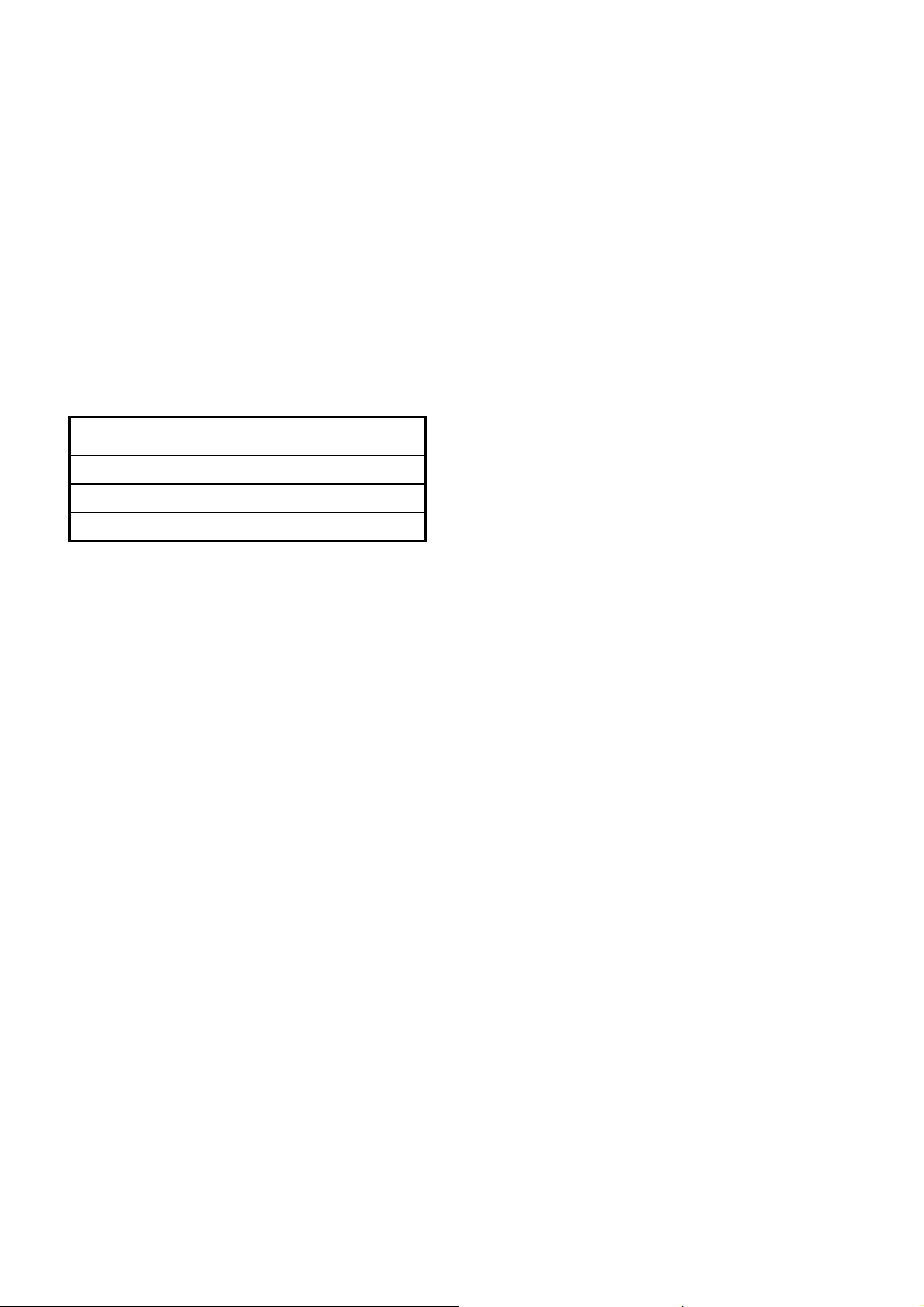
The indicators are used as follows:
Setting Voltage Range
110 V 90 V
220 V 180 V
to 130 V
RMS
RMS
to 265
RMS
RMS
Table: Main Voltage Ranges
2.6 Grounding
In order to protect the user, the unit’s case is grounded through the grounding lead of
the power cable. To ensure proper grounding, the power cable should always be connected to a properly grounded power connector.
The unit case is galvanically separated from the measurement connectors and interface ports.
The back of the unit is equipped with a grounded screw, identified by the
bol, where the user can connect a separate ground line (rack mounting bracket).
sym-
2-4

_____________________________________________________________________________________________________________________________________
2 Getting Started
2.7 Warranty
PREMA warrants the reliable function of the unit for a period of two years from the
date of delivery.
Repairs that need to be carried out during the warranty period are not billed to you.
Damage caused by inappropriate use of the unit, or by surpassing specified limits,
does not fall under PREMA’s warranty obligations.
Please be aware, also, that PREMA will not be held liable for damages, incidental or
coincidental, associated with the use of this measurement device.
2.8 Certificate
Each Digital Multimeter 5017 is provided with a calibration certificate at the factory,
certifying the location, date, and traceability of the unit’s calibration to the user.
Please look for this certificate at delivery time. It can also be useful as a control for
yearly recalibrations, since PREMA warrants that the unit will remain within specifications for one year, and recommends recalibration after that time.
2.9 Turning it on
The multimeter can be switched on with the
STANDBY KEY
cable. A device setting with measurement function, range and time can be stored as a
power-on setting in the "Configure Menu, Settings, Save Settings".
Switch off the instrument also with the
STANDBY KEY
The 5017 is then in standby mode. The red LED at the bottom left of the front panel
lights up.
The analog board of the unit is provided with power, even in standby mode, so that no
warm-up time needs to be taken into account when the unit is turned on.
Otherwise, warm-up times, as provided in Chapter “Technical Specifications”, should
be heeded.
after connecting the power
.
Note: The transformer is not disconnected from Mains Power in standby
mode.
The instrument starts automatically with power-on after switchingoff the unit by pulling the power cord.
2-5
Connection of Measurement Leads
_____________________________________________________________________________________________________________________________________
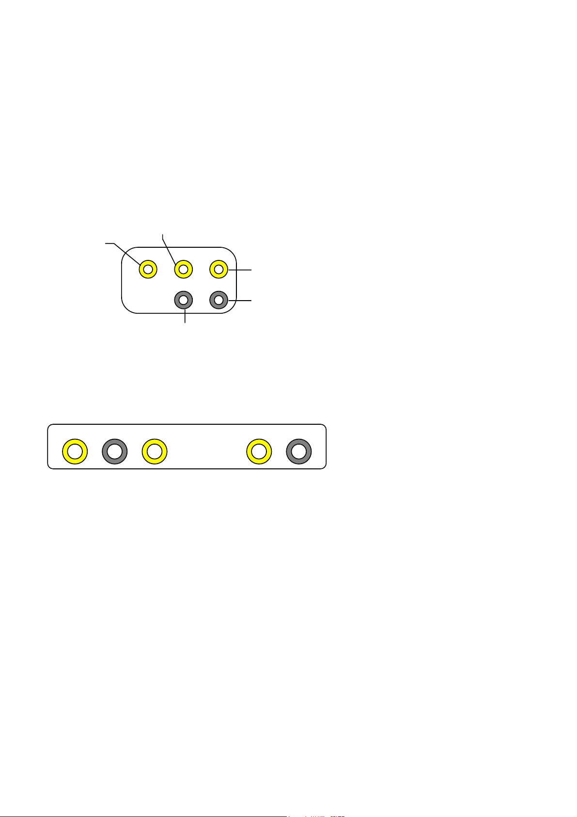
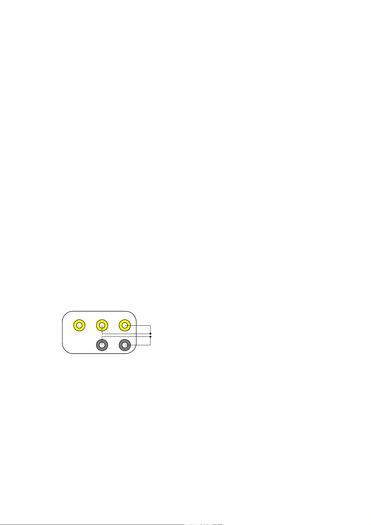
2.10 Connection of Measurement Leads
The measurement inputs are implemented as safety connectors. PREMA strongly recommends the use of safety banana plugs with contact protection (see Appendix A,
“Accessories, Safety Lead Set”).
V-Hi Connector
Amps-Hi
Connector
SenseHiConnector
Sense-Lo
Connector
V-Lo Connector
Figure: Measurement Connectors
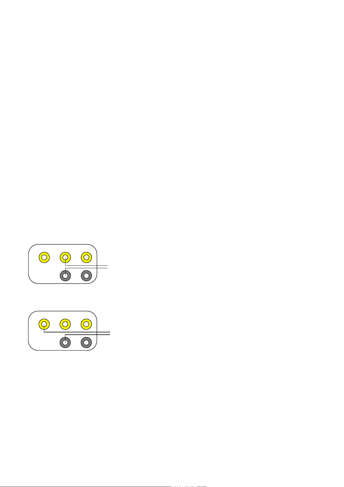
If the 5017 is not equipped with the Scanner option, safety input connectors are also
installed on the rear panel of the unit.
Ω
V
Hi Hi
Amps
Ω
4 W Sense
LoLo Hi
Figure: Rear Panel Input Connectors
Connection of measurement leads should be carried out according to the table on the
next page.
In order to switch to the rear panel input connectors, please read the upcoming section, “Operations with rear panel inputs and Scanner.”
2-6

_____________________________________________________________________________________________________________________________________
The following table gives information about the connection of measurement cables:
Measurement Hi Connector Lo Connector
DC and AC Voltage V-Hi Connector V-Lo Connector
2 Getting Started
DC and AC Current Amps-Hi Connec-
tor
2-wire Resistance V-Hi Connector V-Lo Connector
4-wire Resistance
Source
Sense
Temperature with RTDs
Source
Sense
Frequency / Period
Voltage
Current
Continuity Test V-Hi Connector V-Lo Connector
V-
Hi Connector
Sense-Hi Conn.
V-
Hi Connector
Sense-Hi Conn.
V-Hi Connector
Amps-Hi Conn.
V-Lo Connector
V-
Lo Connector
Sense-Lo Conn.
V-
Lo Connector
Sense-Lo Conn.
V-Lo Connector
V-Lo Connector
Table: Connection of Measurement Cables
In dealing with the Scanner option, please refer to chapter "Technical Specifications"
for information on measurement cable connections. There you will find a full description of the 50-line Sub-D connectors on the rear panel of the unit.
2-7

Rack Mounting
_____________________________________________________________________________________________________________________________________
Operation with rear panel inputs and Scanner
If the 5017 is to be operated from the rear panel inputs or the built-in scanner, please
proceed as follows:
)
1. Please remove all measurement cables from the connectors and
unplug the unit.
2. Turn the unit upside down, so that it is lying on its top shell.
3. Remove the four screws from the unit case's bottom shell.
4. Remove the unit case's bottom shell.
5. Tightly grasp and remove and then swap the two front-rear cable-set connectors that are visible on the left, as seen from the front panel of the unit. Only
the rear cable-set connector is connected to the preamplifier input circuitry.
The front cable-set connector is essentially a place-holder for the input that is
not being used.
6. While re-sealing the case, make sure that no wires are caught anywhere.
After turning the unit on (of course, you should first re-seal the unit’s cover) the
channel indicator field in the display will show the indication “REAR,” or a channel
number (if the Scanner is installed).
The software automatically checks for any rear-panel connections when the unit is
turned on and tests if the cable set connector has been moved from front panel input
to rear-panel input.
2.11 Rack Mounting
A rack adapter with two height units is offered for the 5017. The unit has a width of
one-half 19-inch, so it can be combined with another half-19-inch unit. More information about rack mounting can be found in the Chapter “Accessories.”
When installing the unit into a 19-inch rack, you should take into account, that the
ventilation openings in the back are not covered up. In addition, it should be possible
to cut power to the unit in an emergency, through the use of an EMERGENCY OFF
switch somewhere nearby.
Note: When the unit is installed in a 19-inch rack, and is to be operated through
the rear panel inputs or the Scanner, please make sure that the front-rear
cable-set connector in the unit has been connected to rear-panel input, prior
to installing the unit into the rack (see the previous section on
“Connection of Measurement Leads”).
2-8

_____________________________________________________________________________________________________________________________________
2 Getting Started
2.12 Miscellaneous
Conforming to the Norm EN 61010
The Digital Multimeter 5017 is produced according to EN 61010. This means the
highest possible level of safety for the user, in relation to “dangerous body currents,”
“high temperatures,” and “mechanical endangerment".
This has the consequence, that this unit cannot be switched from front-panel to rearpanel input with a switch, as is found with multimeters of other brands.
The minimum of 5.5mm clearance and creepage distance at a nominal voltage of
1000Vdc is not implemented by standard slide switches. When 1000V are applied to
the front input connectors, and a switch to the rear input connectors is effected by
slider switch, a dangerous transfer of high voltage from the front inputs to the rear
inputs can occur.
In our opinion, the manual re-positioning of the Front-Rear cable-set connector is not
the most elegant, but certainly the safest solution at the moment. This does not mean,
however, that PREMA will not come up with a completely new solution in the future.
Scanner with Model 5017SC
For the model 5017SC with integrated scanner it is important to take the DC and AC
voltage limits of the Scanner into account, depending on which option is installed.
The input voltage at the rear panel is limited to 125 Vpk with the standard scanner
option.
The limit of 1000Vpk continues to be valid for the front input connectors only.
Current measurement and the 1000V range can only be selected while using the front
input connectors .
2-9

Miscellaneous
_____________________________________________________________________________________________________________________________________
2-10

_____________________________________________________________________________________________________________________________________
3 Quick Start
3 Quick Start
3.1 Default Settings
When the unit is turned on for the first time, the following settings are defaulted to:
Measurement Function Vdc
•
Measurement Range 300V
•
Measurement Time 1s
•
Front Input Connectors Active
•
Automatic Filter On (AVG 10)
•
Pt100 sensor for temperature measurement
•
• all other functions switched off
The power-on setting can be stored in the menu "Configure, Settings, Save" .
You can set the instrument to the factory settings with the menu "Configure, Settings,
Load Fact, Set".
3.2 Scanner (5017SC)
You can find the inputs of the scanner on the rear panel of the instrument. When delivered the front input connectors are active.
The connections to the scanner can be done with two 50-pole sub-D connectors or
two adaptercards 3110 (see chapters "Accessories" and "Technical Specifications").
3-1

Measuring Voltage
_____________________________________________________________________________________________________________________________________
3.3 Measuring Voltage
Measurement Functions
DC Voltage
AC Voltage
AC Voltage with DC Component
VDC
VAC
VAC
key
key
key and
COUPL
key
Measurement Ranges
Vdc 300mV, 3V, 30V, 300V, 1000V
Vac 200mV, 2V, 20V, 200V, 700V
Resolution and Measurement Times
Vdc 20 / 40 / 100 ms 5½ digits
200 / 400 ms / 1s 6½ digits
2 / 4 / 10 / 20 / 40 / 100 s 7½ digits
Vac 100 ms 5½ digits
0.2 / 0.4 / 1 / 2 / 4 / 10 / 20 / 40 / 100s 6½ digits
max. Resolution in the smallest range Vdc: 10nV Vac: 100nV
Frequency Range Vac: 20 Hz to 1 MHz
Amps
HI HI
V
Ω
LO
Ω4
Sense
+
DC or AC Voltage
__
Figure: Connection of measurement leads in Voltage Measurement
The rear plugs are connected correspondingly.
For model 5017SC with scanner the measurement leads are connected to Hi and Lo of
the respective channel.
3-2
_____________________________________________________________________________________________________________________________________
3 Quick Start
3.4 Measuring Current
Measurement Functions
DC Current
AC Current
AC Current with DC Component
IDC
IAC
IAC
key
key
key and
COUPL
key
Measurement Ranges
Idc 200 µA, 2 mA, 20 mA, 200 mA, 2 A
Iac 200 µA, 2 mA, 20 mA, 200 mA, 2 A
Resolution and Measurement Times
Idc 20 / 40 / 100 ms 5½ digits
0.2s to 100s 6½ digits
Iac 100 / 200 ms 5½ digits
400 ms / 1 / 2 / 4 / 10 / 20 / 40 / 100 s 6½ digits
Frequency Range Iac: 20 Hz to 5kHz
max. Resolution in the smallest range Idc: 100pA Iac: 100pA
V
Amps
HI HI
Ω
LO
Ω4
Sense
+
_
DC or AC
Current
Figure: Connection of measurement leads in Current Measurement
The rear plugs are connected correspondingly.
For model 5017SC with scanner current measurement is possible only through the
front plugs.
3-3
Measuring Resistance
_____________________________________________________________________________________________________________________________________
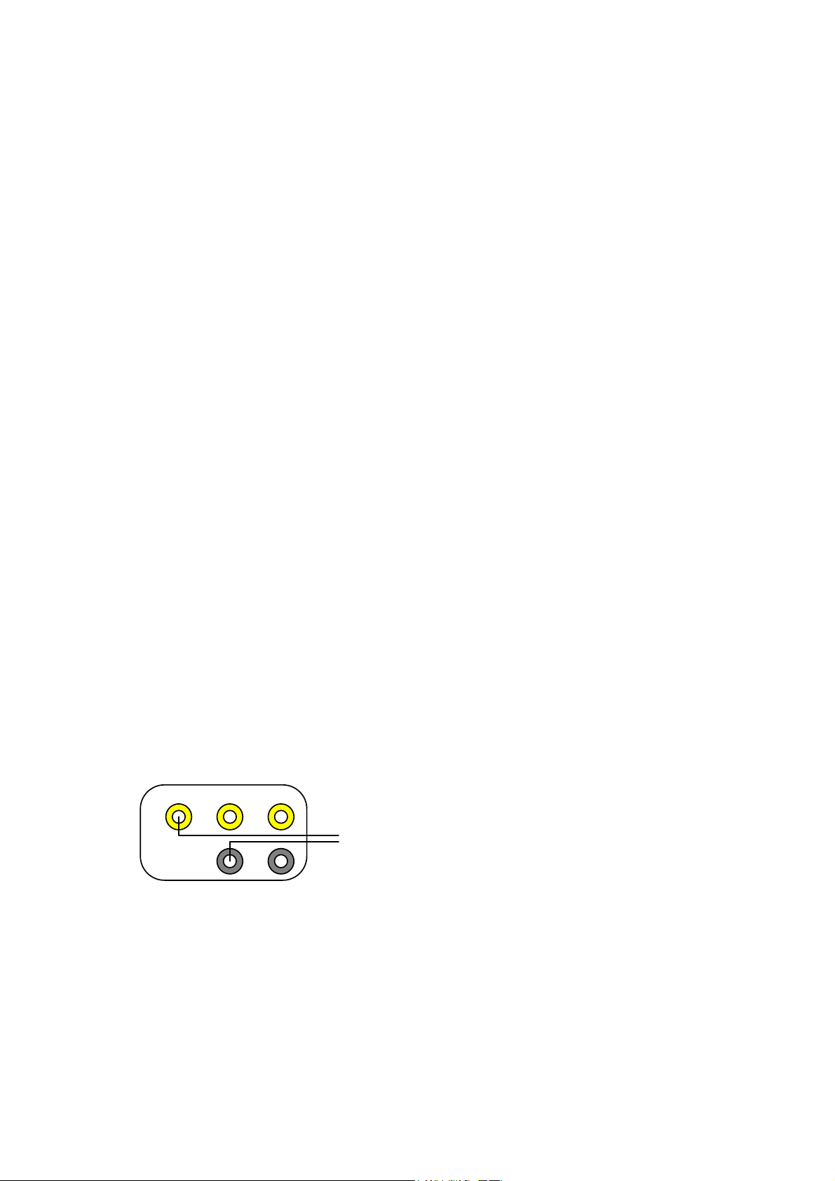
3.5 Measuring Resistance
Measurement Functions
2-Wire Resistance Measurement Ω2
4-Wire Resistance Measurement Ω4
W
W
key
key
Measurement Ranges
300 Ω, 3 kΩ, 30 kΩ, 300 kΩ, 3 MΩ, 30 MΩ
Measurement Times
20 / 40 / 100 ms 5½ digits
200 / 400 ms / 1s 6½ digits
2 / 4 / 10 / 20 / 40 / 100 s 7½ digits
max. Resolution in the smallest range 7½ digits, 10µ
Ω
LO
Ω4
Sense
Resistance
2-wire
Amps V
HI HI
Ω
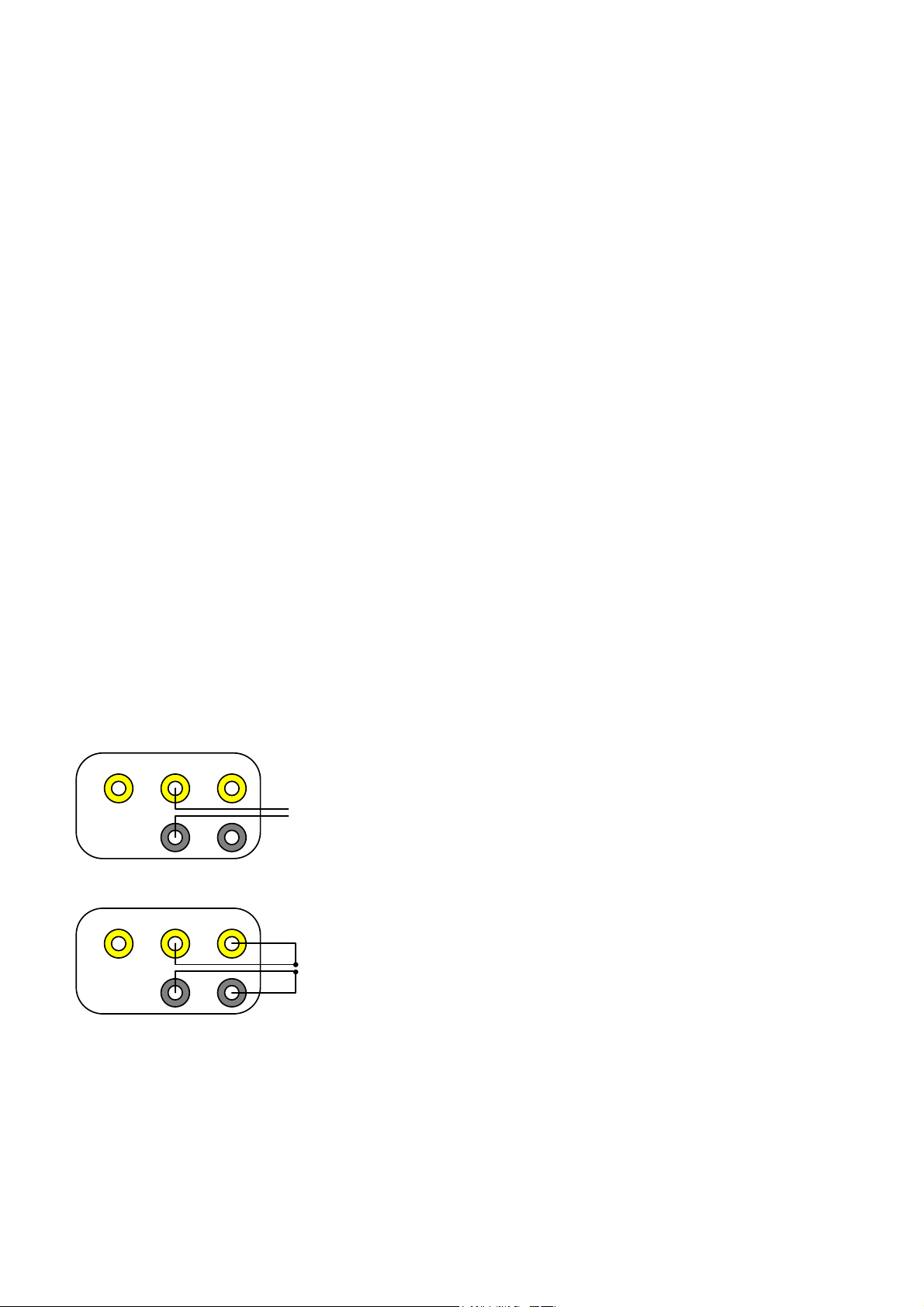
Figure: Connection of leads in resistance measurement (2-wire)
Amps V
HI HI
Ω
LO
Ω4
Sense
Resistance
4-wire
Figure: Connection of leads in resistance measurement (4-wire)
The rear plugs are connected correspondingly.
For model 5017SC with scanner the measurement leads are connected to Hi and Lo
(2-wire) or Hi, Lo (Source) and SHi, SLo (Sense) of the respective channel.
3-4
_____________________________________________________________________________________________________________________________________
3 Quick Start
3.6 Measuring Temperature
Sensors
RTDs: Pt10, Pt25, Pt100, Pt500, Pt1000
Sensor Configuration
in the menu "Device, Temp Sensor"
Resolution and Measurement Times
0.01 K / 0.01°C / 0.01°F 100 / 200 / 400 ms
0.001 K / 0.001°C / 0.001°F 1 s to 100 s
Select °C / °F / K press
Amps V
HI HI
ΩΩ4
Sense
RTD
Sensors
LO
TEMP
Figure: Connection of measurement leads for RTD Sensors
key again
The rear plugs are connected correspondingly.
For model 5017SC with scanner the measurement leads are connected to Hi, Lo
(Source) and SHi, SLo (Sense) of the respective channel.
3-5
Frequency and Period Measurement
_____________________________________________________________________________________________________________________________________
3.7 Frequency and Period Measurement
Measurement Functions
Frequency for Vac
Period for Vac
Frequency for Iac
Period for Iac
VAC
VAC
IAC
IAC
key and
key and
key and
key and
FREQ
PERIOD
key
FREQ
PERIOD
key
key
key
Select first the function Vac or Iac and adapt the right measurement range. Then select the frequency function.
Time Base 10ms / 100ms / 1s / 10s
Resolution
Frequency 1 Hz, max. 7½ digits, max. frequency 1MHz
Period Vac: 40µs to 5s / Iac: 100µs to 5s
Amps V
HI HI
ΩΩ4
LO
Sense
+
Frequency and Period
Measurement
__
with Voltage
Figure: Connection of Leads in Freq. Meas. of a Voltage
Amps V
HI HI
ΩΩ4
LO
Sense
+_Frequency and Period
Measurement
with Current
Figure: Connection of Meas. Leads in Freq. Meas. of a Current
The rear plugs are connected correspondingly.
For model 5017SC with scanner the measurement leads are connected to Hi and Lo
(Voltage) of the respective channel.
Frequency measurement of a current is only possible through the front plugs.
3-6

_____________________________________________________________________________________________________________________________________
3 Quick Start
3.8 Continuity Test
The continuity test can be selected with the
CONT KEY
.
Continuity Test Activate loudspeaker at 50Ω
Display: open or close
3.9 Selecting Measurement Ranges
The measurement range can be changed with the
AUTO KEY
key is used to automatically pre-select a measurement range (2nd +
Ø key and the × key. The 2
MenuOut key). The “AUTO” indication then appears in the status display.
If the measurement range is set manually, and a measurement signal is too large for
that range, “Overflow” will be indicated on the display.
If automatic ranging is on, a higher measurement range is automatically selected
when a display of about 190 000 *) digits is reached. A lower measurement range is
selected when a reading of lower than about 10 000 *) is reached.
Automatic range switching occurs within <5ms.
ND
-
Note: The measurement range and the integration time are stored for every
measurement function.
*) for 5-½ digit display
3-7
Setting the Integration Time / Resolution
_____________________________________________________________________________________________________________________________________
3.10 Setting the Integration Time / Resolution
The integration time (and consequently the resolution) can be changed with the
and the cursor keys. The ×
KEY
increases the integration time, the Ø
KEY
KEY
creases the integration time.
Integration Time Resolution
20ms, 40ms, 100ms 5½ Digits
200ms, 400ms, 1s 6½ Digits
2s to 100s 7½ Digits *)
*) for Vdc and
Ω
Table: Integration Times and Resolutions
Note: Range and Integration Time are stored for the respective measurement
function.
TIME
de-
3-8
_____________________________________________________________________________________________________________________________________
3.11 Display
The display can be changed and configured in the menu "Device, Display",
format.
Display with Settings
3 Quick Start
MATH FILT REM
REAR
9 ÞÞßß
TRIG STORE ADR
Figure: Display with Settings
Selecting with Menu "Device, Display, Settings".
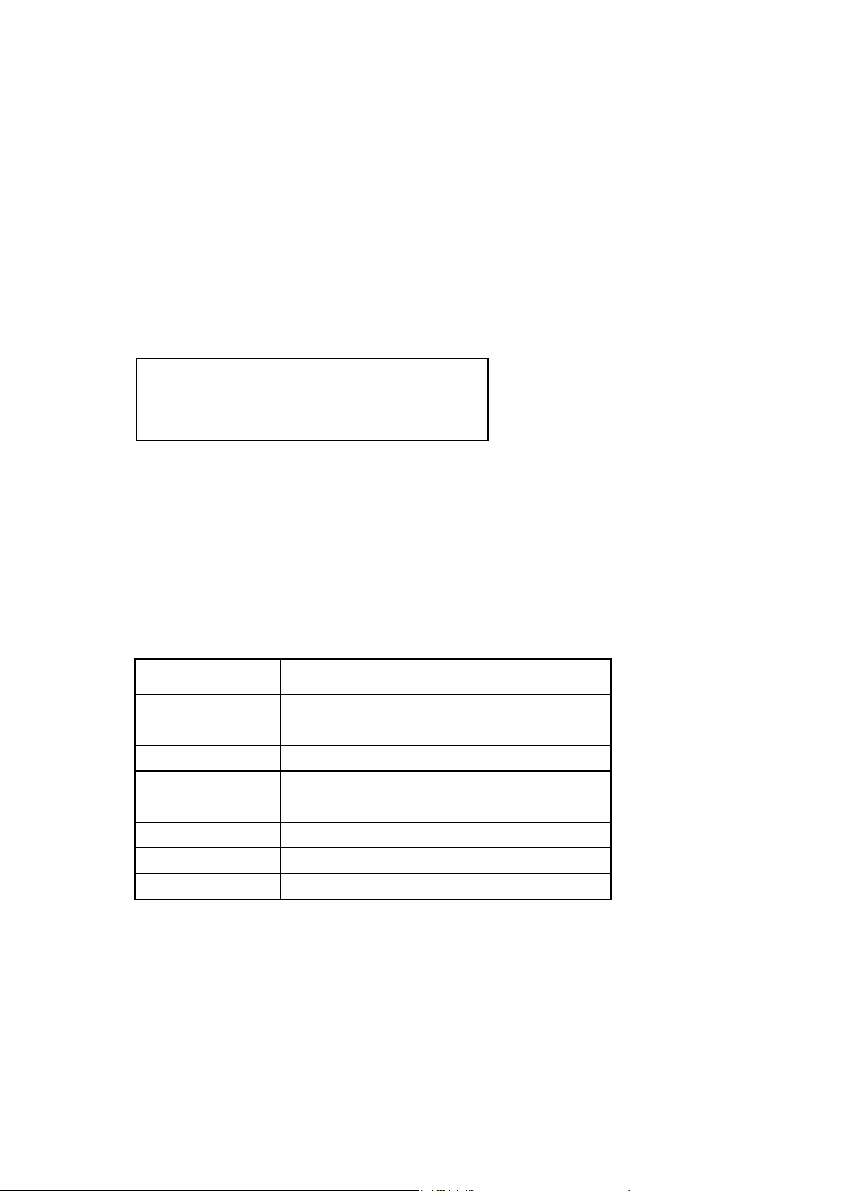
Meaning of the Settings
Settings Bedeutung
REAR Rear inputs are active
MATH Mathematic program is active
FILT Filter is switched on
AUTO
REM Device is in remote mode
AUTO Auto Ranging is switched on
TRIG Device is in trigger mode
STORE not used
ADR Device is in talker / listener mode
Table: Meaning of the Settings
3-9
 Loading...