

Page 1
_____________________________________________________________________________________________________________________________________
DIGITAL MULTIMETER 5017
7 ½ Digit Precision Multimeter with IEEE-488 and RS232 Interface
PREMA Semiconductor GmbH
Robert-Bosch-Str. 6
•
D-55129 Mainz • Germany
Tel. +49-6131-5062-20
•
Fax. +49-6131-5062-22
E-Mail: instruments @ prema.com
AS5017-0045
Internet: http: / / www.prema.com
Subject to change without notice
DMM 5017 / DMM 5017 SC
User´s Manual
Page 2

Table of Contents
_____________________________________________________________________________________________________________________________________
1
Table of Contents
TABLE OF CONTENTS 1
1 INTRODUCTION 1-1
1.1 Features 1-1
1.2 Various Versions 1-1
1.3 Important Safety Instructions 1-2
Reading the User Manual 1-2
Further Safety Instructions 1-2
Predictability of Dangers 1-3
Proprietary Rights 1-3
Conformity Declaration 1-3
Proper Utilization as intended 1-3
Availability of the User Manual 1-5
2 GETTING STARTED 2-1
2.1 Delivery 2-1
2.2 Safety Guidelines 2-2
Utilization 2-2
2.3 Safety Symbols 2-3
2.4 Accident Prevention 2-3
2.5 Connecting the Unit to Main Power 2-3
2.6 Grounding 2-4
2.7 Warranty 2-5
2.8 Certificate 2-5
2.9 Turning it on 2-5
2.10 Connection of Measurement Leads 2-6
Operation with rear panel inputs and Scanner 2-8
2.11 Rack Mounting 2-8
2.12 Miscellaneous 2-9
Conforming to the Norm EN 61010 2-9
Scanner with Model 5017SC 2-9
3 QUICK START 3-1
3.1 Default Settings 3-1
3.2 Scanner (5017SC) 3-1
3.3 Measuring Voltage 3-2
3.4 Measuring Current 3-3
Page 3

Table of Contents
_____________________________________________________________________________________________________________________________________
2
3.5 Measuring Resistance 3-4
3.6 Measuring Temperature 3-5
3.7 Frequency and Period Measurement 3-6
3.8 Continuity Test 3-7
3.9 Selecting Measurement Ranges 3-7
3.10 Setting the Integration Time / Resolution 3-8
3.11 Display 3-9
Display with Settings 3-9
Meaning of the Settings 3-9
Display with Mathematics 3-10
Display with Channel 3-10
Display with Time Counter 3-11
4 MANUAL OPERATION 4-1
4.1 Keypad 4-1
The Function Field 4-2
The Range / Menu Field 4-3
4.2 The Display Field 4-4
Display Elements 4-4
4.3 Measuring Inputs 4-5
Connecting the Measuring Cables 4-5
Limiting Data for the Measuring Inputs 4-6
4.4 Setting the Measuring Functions 4-7
4.5 Measuring Range Selection 4-7
4.6 Channel Selection for 5017SC 4-8
4.7 Offset Correction 4-8
4.8 Navigating in the Menu Structure 4-9
4.9 Mathematical Programs 4-11
Selection / Manual Control 4-11
Meaning of the Mathematical Programs 4-12
4.10 The Menu "Configure" 4-13
Start Mode / Trigger Mode 4-13
Filter 4-13
Automatic Filter (Auto Filter) 4-14
Fast Automatic Filter (Fast Auto Filter) 4-14
Moving Average Filter (Avg. Filter) 4-14
Filter Selection 4-15
Saving and Loading Instrument Settings 4-15
Power-Up Status 4-16
Calibration 4-16
4.11 The Menu "Device" 4-17
Setting the Contrast 4-17
Preselecting the Interface 4-18
Page 4

Table of Contents
_____________________________________________________________________________________________________________________________________
3
Preselecting the Command Set for Remote Control 4-19
Selecting the Temperature Sensor 4-20
Activating the Loudspeaker 4-21
Setting the Display Formats 4-21
Setting the Scanner Mode 4-23
4.12 Error Messages 4-24
5 REMOTE CONTROL 5-1
5.1 Configuration 5-1
Select Interface 5-1
Configuring the RS232 Interface 5-1
Configuring the IEEE-488 Interface 5-2
Define the Command Set 5-2
5.2 General Information concerning Remote Control 5-3
5.3 Special Features for the RS232 Interface 5-3
5.4 Capabilities of the IEEE-488 Bus Interface 5-4
General IEEE-488.1 Messages 5-4
5.5 RS232 / IEEE-488.2 Common Commands 5-5
*CLS, Clear Status Command 5-5
*ESE Standard Event Status Enable Command 5-6
*ESE? Standard Event Status Enable Query 5-6
*ESR? Standard Event Status Register Query 5-6
*IDN? Identification Query 5-7
*OPC Operation Completed Command 5-7
*OPC? Operation Completed Query 5-7
*RST Reset Command 5-7
*SRE Service Request Enable Command 5-8
*SRE? Service Request Enable Query 5-8
*STB? Read Status Byte Query 5-8
*TST? Self Test Query 5-9
*WAI Wait-to-Continue Command 5-9
5.6 Structure of the Registers 5-10
5.7 Operation as Listener 5-11
5.8 Display Mode 5-14
5.9 String Length Selection 5-16
5.10 SRQ Mode 5-16
5.11 Operation of the Digital Multimeter as TALKER 5-16
Description of the Message Record Sent 5-17
Table of Device Messages sent by the Multimeter 5-18
Meaning of the Transmitted Characters 5-19
5.12 Error Messages 5-21
5.13 Compatibility 5-23
5017 as Listener 5-23
Page 5

Table of Contents
_____________________________________________________________________________________________________________________________________
4
5017 as Talker 5-25
Difference between 5017 and 6001 concerning hardware 5-27
6 CALIBRATION 6-1
6.1 Calibration Periods 6-1
6.2 PREMA Calibration Service 6-1
6.3 Necessary Equipment 6-1
6.4 Automated Calibration 6-2
6.5 Important Steps prior to Calibration 6-3
6.6 PIN Number and Calibration Switch 6-4
Changing the PIN Number 6-5
6.7 Offset Correction 6-6
6.8 Calibrating DC Voltage 6-7
Offset Correction for DC Voltage 6-7
Calibration of DC Voltage 6-7
6.9 Calibration of Resistance Ranges 6-8
Offset Correction 6-8
Calibration of Resistance 6-8
6.10 Calibration of AC Voltage 6-9
6.11 Calibration of DC and AC Current 6-9
6.12 Calibration of Temperature 6-9
6.13 Storing Calibration Values 6-11
7 OPERATING INSTRUCTIONS 7-1
7.1 DC Voltage Measurement 7-1
Input Resistance in DC Voltage 7-1
Series Mode Suppression 7-2
Common Mode Suppression 7-3
Thermal Voltages 7-3
Noise Effects Through Inductive Interferences 7-4
7.2 Resistance Measurement 7-5
Two-Wire Resistance Measurement 7-5
Four-Wire Resistance Measurement 7-7
Power Dissipation in the Resistors 7-8
7.3 AC Voltage Measurement 7-8
7.4 DC and AC Current 7-9
7.5 Temperature Measurement 7-10
8 CONSTRUCTION 8-1
8.1 Input Circuit 8-1
8.2 Integrating A to D Converter 8-2
Mains Synchronization 8-3
Page 6

Table of Contents
_____________________________________________________________________________________________________________________________________
5
Reference 8-4
8.3 Measurement of AC Voltage 8-5
Frequency, Period 8-5
RMS to DC Converter 8-5
8.4 Application of Microprocessors 8-6
Main Processor 8-6
Power Management 8-7
Other processors 8-7
8.5 Ports 8-8
Display 8-8
Memory 8-8
Serial Port 8-8
IEEE-488 Port 8-8
Trigger Port 8-8
8.6 Measurement Inputs 8-9
Front / Rear Measurement Connectors 8-9
8.7 Power 8-9
8.8 5017SC 8-10
Scanner 8-10
9 TECHNICAL SPECIFICATIONS 9-1
9.1 DC Voltage 9-1
9.2 Resistance 9-5
9.3 AC Voltage 9-7
9.4 DC Current 9-9
9.5 AC Current 9-11
9.6 Temperature 9-12
9.7 Frequency and Period 9-14
9.8 Special Functions 9-15
9.9 Scanner with Model 5017SC 9-16
Pin Assignment of the Scanner 9-17
9.10 IEEE-488 Interface 9-19
9.11 RS232 Serial Interface 9-21
9.12 Trigger Interface 9-23
9.13 EU Conformity 9-24
EMC Compliance Tests 9-24
Measurement of the EMI Emissions 9-24
Measurement of EMI Immunity 9-25
9.14 General 9-26
10 ACCESSORIES 10-1
10.1 Adaptercard (3110) 10-1
10.2 Mating Plug for Sub-D (6000/03) 10-2
Page 7

Table of Contents
_____________________________________________________________________________________________________________________________________
6
10.3 Pt100 Temperature Probes (3011 and 3012) 10-2
10.4 Test Lead Set (3014) 10-2
10.5 Set of Short Circuit Plugs (3016) 10-3
10.6 Current Shunt (3017) 10-3
10.7 RS232 Cable (3018) 10-3
10.8 Carrying Case (4100) 10-3
10.9 Accessories for the IEEE488 Bus 10-3
10.10 19-inch Rack Mounting Kit (5021 G) 10-4
INDEX R-1
Page 8

1 Introduction
_____________________________________________________________________________________________________________________________________
1-1
1 Introduction
With the Digital Multimeter 5017 you are now the owner of a 7 ½ digit measuring
instrument of the newest generation from PREMA.
This instrument is convincing by virtue of its outstanding measuring capabilities and
functional versatility.
1.1 Features
The following features of the 5017 are of special interest:
• Very good stability with only 4 ppm tolerance and annual drift of 20 ppm.
•
Additional measuring functions such as frequency and period duration.
• Temperature measurement with various Pt sensors
(Pt10, Pt25, Pt100, Pt500 and Pt1000)
• Good system capabilities with the RS232 and the IEEE-488 interface
• Large clearly readable liquid crystal display (LCD)
• Standard case dimensions: Half 19 inch width and 2 height units.
•
The 5017SC with built-in scanner for up to 80 measuring
points (80x1-pole, 40x2-pole, 20x4-pole)
1.2 Various Versions
In the standard version, the 5017 is fitted with banana safety sockets on the rear in
addition to the front panel sockets. A scanner is incorporated in the 5017SC. The
scanner connections are located on the rear panel in the form of 50-pole SubD sockets. An adapter card is available (see chapter ‘Accessories’) for connecting the scanner via screw terminals.
Prior to using the connections on the rear, a plug strip connector must be transferred
inside the instrument. The designator "Rear" is then lit in the display.
For the 5017SC current measuring ranges and the 1000V range can be selected only
when using the front panel sockets (maximum permissible voltage 125 Vpk at the
scanners rear input).
Page 9

Important Safety Instructions
_____________________________________________________________________________________________________________________________________
1-2
1.3 Important Safety Instructions
Reading the User Manual
Proper working procedure with this instrument is possible only after reading all instructions, hints and procedure specifications attentively and understanding them.
Please get in touch with PREMA before commencing operation of the instrument if
you do not understand something in the user manual or the instructions, procedural
descriptions and safety regulations are unclear.
This user manual has been written to make the instrument understandable for operation in the manner intended. It contains important instructions for safe, correct and
efficient operation of the instrument.
Dangers are avoided, repair costs and downtime reduced and the service life of the
instrument is extended only when these instructions are observed. The user manual
should always be available at the place where the instrument is operated.
Incorrect manual control or failure to observe the instructions given here may endanger persons (also third parties) or cause material damage.
Personnel entrusted with operating this instrument must have read this user manual
attentively and must be familiar with all safety instructions.
In addition to the instructions given in this user manual, the local regulations for preventing accidents in force at the operating site apply, as well as the relevant rules for
safe and proper working procedure.
Further Safety Instructions
Further safety instructions are contained in the chapter headed "Getting
Started".Explanations and instructions are given there for the warning signs and symbols on the instrument for recognising specific sources of danger. It is essential to
observe and comply with all safety instructions. The warning symbols must be held
complete and in good readable condition.
Page 10

1 Introduction
_____________________________________________________________________________________________________________________________________
1-3
Predictability of Dangers
The manufacturer cannot anticipate every conceivable danger.
If a task is not carried out in the manner recommended, the operator must make sure
that this does not entail any danger for himself and other persons.
He should also make sure that the instrument cannot be damaged or endangered by
the chosen manner of operation.
This user operating manual is not an instruction manual for making repairs.
The instrument should be returned to the factory for any necessary repairs.
Proprietary Rights
This user manual is protected by proprietary rights. No part thereof may be copied,
reproduced or distributed in any form without prior written permission.
Conformity Declaration
PREMA has issued an EC conformity declaration for this instrument. This declaration
certifies that the instrument complies with the relevant requirements of the EC directives.
Proper Utilization as intended
These instruments have been built conforming to the recognized technical safety principles, but nevertheless if it is not used and operated in the manner intended, dangers
may arise for body and life of the user or third persons, or damage may be incurred by
the instrument and other objects.
The instrument may therefore be operated only in technically perfect condition, in the
manner intended and with due awareness of safety considerations and dangers, observing the contents of the user manual and the regulations for the prevention of accidents. It should be used exclusively for the tasks described in this user manual.
All faults on the instruments which impair the safety of the user or third persons must
be remedied immediately.
PREMA accepts no liability for damage resulting from utilization of this instrument
in any manner other than the intended manner described in the user manual. The user
alone carries the risk and responsibility for any deviating utilization of the instrument.
Page 11

Important Safety Instructions
_____________________________________________________________________________________________________________________________________
1-4
Availability of the User Manual
The user manual must always be available at the place where this instrument is operated. The personnel entrusted with operation of this instrument must be familiar with
all task procedures described in the user manual and with all safety instructions.
All warning and safety instructions attached to the instrument must be held complete
and in clearly readable condition.
No modifications, attachments or conversions of the instruments are permitted without consent and approval by PREMA, otherwise the conformity becomes void.
Page 12

2 Getting Started
_____________________________________________________________________________________________________________________________________
2-1
2 Getting Started
2.1 Delivery
Every PREMA unit is thoroughly and carefully checked before it is shipped, to ensure
that it is in flawless condition, and that its technical characteristics are within specifications.
Consequently, upon receipt, the unit should be in perfect condition, mechanically and
electrically.
To make sure that the unit has not been damaged during transport, it should be thoroughly checked out immediately after receipt. If damage is detected, a damage claims
form should be completed with the shipping carrier.
Please use the following list to assure that delivery is complete:
)
1. Power Cable
2. User Manual, English
3. Calibration Certificate with Date and Signatures
4. Product Registration Card, which you should fill out and mail back to
PREMA
5. Any optional equipment ordered
Please ensure also, that the unit is set up for the right AC Voltage, with the right type
of fuse (see chapter “Connecting the Unit to Main Power”).
Important: Do not throw the box and packaging materials away!
If the unit has to be sent back to the factory for recalibration or repair,
only the original packaging materials will provide sufficient protection
against damage.
Page 13

Safety Guidelines
_____________________________________________________________________________________________________________________________________
2-2
2.2 Safety Guidelines
Also refer to the safety guidelines in the “Introduction” chapter, please.
The multimeter may only be operated if it is in perfect and safe condition. Accident
prevention and environmental protection rules must also be followed.
All power-up and power-down procedures described next must be followed. Problems, such as loose connections, damaged or scorched cables, oxidized contacts, and
damaged fuses must be immediately removed by a professional.
A safe and ecologically sound disposal of operating and support materials, as well as
replacement parts, must be arranged. Only genuine replacement parts shall be used.
Otherwise, the manufacturer’s warranty and the multimeter’s conformity will be
voided.
Any changes to the multimeter, which cause any functional changes, may only be carried out by the manufacturer, or after discussion with and permission by the manufacturer.
Note: Switching operation to the rear panel connectors (or to the scanner) may
only be carried out by a professional (see “Connection of Measurement
Leads").
Utilization
The multimeter may only be utilized for the measurement functions that are described
in the Technical Specifications. It is especially important to adhere to the load limits
of the input connectors. PREMA accepts no responsibility for any damage arising
from improper operation.
Page 14

2 Getting Started
_____________________________________________________________________________________________________________________________________
2-3
2.3 Safety Symbols
The signs and symbols on the multimeter, which provide guidelines for safety and
handling, are displayed and described below.
This symbol advises the user of a possible danger area.
Please consult the manual (see “Connection of Measurement
Leads” and Chapter “Operating Instructions”).
This symbol makes the user aware, that a dangerous
voltage can be present at measurement connectors.
The CE mark means, that the manufacturer has issued an
EC Declaration of Conformity for this multimeter. This declaration
certifies, that this multimeter conforms to the pertinent requirements
of EC directives.
2.4 Accident Prevention
While using this measurement unit, precautions to prevent an accident should be
taken, appropriate to the use of a measurement device.
It is especially important to observe , that during current measurement, a very low
impedance i.e. 0.1Ω exists between the Hi and Lo connectors, so that a current/voltage, which is applied to the Hi connector, can be contacted by a cable that is
connected to the Lo connector.
2.5 Connecting the Unit to Main Power
This PREMA measurement unit is designed to be connected to AC Main Voltage, at a
frequency of 50 Hz or 60 Hz. The rear panel of the unit is equipped with a standard
DIN grounded power connector.
!
Page 15

Grounding
_____________________________________________________________________________________________________________________________________
2-4
Before connecting the unit to power, you should make sure that it is set to the right
voltage (indicator and fuse).
The voltage selection switch with integrated fuse is located right under the power
connector, where you can also read off the current voltage setting; a setting of
"220V" represents an AC voltage from 220V to 240V, "110V" represents a voltage
from 100V to 120V.
Switching the AC Voltage is done as follows:
)
1. Unplug the unit.
2. The clamp for the fuse is located between the plug and the power selector and
must be removed. For a setting of "110V" you will need a fuse rated at 0.4A;
for "220V" you’ll need a fuse rated at 0.2A.
3. Place the necessary fuse in the clamp and push the clamp back in.
4. Turn the cylinder with the voltage indicators once left or once right to the desired setting, so that the voltage that is currently set is indicated by the white
arrow on top.
The indicators are used as follows:
Setting Voltage Range
110 V 90 V
RMS
to 130 V
RMS
220 V 180 V
RMS
to 265
RMS
Table: Main Voltage Ranges
2.6 Grounding
In order to protect the user, the unit’s case is grounded through the grounding lead of
the power cable. To ensure proper grounding, the power cable should always be connected to a properly grounded power connector.
The unit case is galvanically separated from the measurement connectors and interface ports.
The back of the unit is equipped with a grounded screw, identified by the
sym-
bol, where the user can connect a separate ground line (rack mounting bracket).
Page 16

2 Getting Started
_____________________________________________________________________________________________________________________________________
2-5
2.7 Warranty
PREMA warrants the reliable function of the unit for a period of two years from the
date of delivery.
Repairs that need to be carried out during the warranty period are not billed to you.
Damage caused by inappropriate use of the unit, or by surpassing specified limits,
does not fall under PREMA’s warranty obligations.
Please be aware, also, that PREMA will not be held liable for damages, incidental or
coincidental, associated with the use of this measurement device.
2.8 Certificate
Each Digital Multimeter 5017 is provided with a calibration certificate at the factory,
certifying the location, date, and traceability of the unit’s calibration to the user.
Please look for this certificate at delivery time. It can also be useful as a control for
yearly recalibrations, since PREMA warrants that the unit will remain within specifications for one year, and recommends recalibration after that time.
2.9 Turning it on
The multimeter can be switched on with the
STANDBY KEY
after connecting the power
cable. A device setting with measurement function, range and time can be stored as a
power-on setting in the "Configure Menu, Settings, Save Settings".
Switch off the instrument also with the
STANDBY KEY
.
The 5017 is then in standby mode. The red LED at the bottom left of the front panel
lights up.
The analog board of the unit is provided with power, even in standby mode, so that no
warm-up time needs to be taken into account when the unit is turned on.
Otherwise, warm-up times, as provided in Chapter “Technical Specifications”, should
be heeded.
Note: The transformer is not disconnected from Mains Power in standby
mode.
The instrument starts automatically with power-on after switchingoff the unit by pulling the power cord.
Page 17
Connection of Measurement Leads
_____________________________________________________________________________________________________________________________________
2-6
2.10 Connection of Measurement Leads
The measurement inputs are implemented as safety connectors. PREMA strongly recommends the use of safety banana plugs with contact protection (see Appendix A,
“Accessories, Safety Lead Set”).
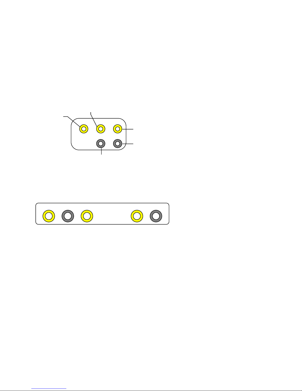
Figure: Measurement Connectors
If the 5017 is not equipped with the Scanner option, safety input connectors are also
installed on the rear panel of the unit.
Figure: Rear Panel Input Connectors
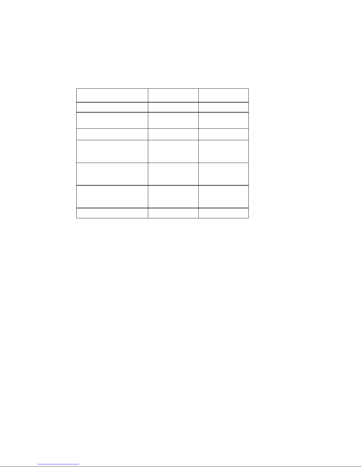
Connection of measurement leads should be carried out according to the table on the
next page.
In order to switch to the rear panel input connectors, please read the upcoming section, “Operations with rear panel inputs and Scanner.”
V-Hi Connector
V-Lo Connector
Amps-Hi
Connector
Connector
Sense-Lo
SenseHi-
Connector
V
Ω
Hi Hi
Amps
Ω
4 W Sense
LoLo Hi
Page 18
2 Getting Started
_____________________________________________________________________________________________________________________________________
2-7
The following table gives information about the connection of measurement cables:
Measurement Hi Connector Lo Connector
DC and AC Voltage V-Hi Connector V-Lo Connector
DC and AC Current Amps-Hi Connec-
tor
V-Lo Connector
2-wire Resistance V-Hi Connector V-Lo Connector
4-wire Resistance
Source
Sense
V-
Hi Connector
Sense-Hi Conn.
V-
Lo Connector
Sense-Lo Conn.
Temperature with RTDs
Source
Sense
V-
Hi Connector
Sense-Hi Conn.
V-
Lo Connector
Sense-Lo Conn.
Frequency / Period
Voltage
Current
V-Hi Connector
Amps-Hi Conn.
V-Lo Connector
V-Lo Connector
Continuity Test V-Hi Connector V-Lo Connector
Table: Connection of Measurement Cables
In dealing with the Scanner option, please refer to chapter "Technical Specifications"
for information on measurement cable connections. There you will find a full description of the 50-line Sub-D connectors on the rear panel of the unit.
Page 19

Rack Mounting
_____________________________________________________________________________________________________________________________________
2-8
Operation with rear panel inputs and Scanner
If the 5017 is to be operated from the rear panel inputs or the built-in scanner, please
proceed as follows:
)
1. Please remove all measurement cables from the connectors and
unplug the unit.
2. Turn the unit upside down, so that it is lying on its top shell.
3. Remove the four screws from the unit case's bottom shell.
4. Remove the unit case's bottom shell.
5. Tightly grasp and remove and then swap the two front-rear cable-set connectors that are visible on the left, as seen from the front panel of the unit. Only
the rear cable-set connector is connected to the preamplifier input circuitry.
The front cable-set connector is essentially a place-holder for the input that is
not being used.
6. While re-sealing the case, make sure that no wires are caught anywhere.
After turning the unit on (of course, you should first re-seal the unit’s cover) the
channel indicator field in the display will show the indication “REAR,” or a channel
number (if the Scanner is installed).
The software automatically checks for any rear-panel connections when the unit is
turned on and tests if the cable set connector has been moved from front panel input
to rear-panel input.
2.11 Rack Mounting
A rack adapter with two height units is offered for the 5017. The unit has a width of
one-half 19-inch, so it can be combined with another half-19-inch unit. More information about rack mounting can be found in the Chapter “Accessories.”
When installing the unit into a 19-inch rack, you should take into account, that the
ventilation openings in the back are not covered up. In addition, it should be possible
to cut power to the unit in an emergency, through the use of an EMERGENCY OFF
switch somewhere nearby.
Note: When the unit is installed in a 19-inch rack, and is to be operated through
the rear panel inputs or the Scanner, please make sure that the front-rear
cable-set connector in the unit has been connected to rear-panel input, prior
to installing the unit into the rack (see the previous section on
“Connection of Measurement Leads”).
Page 20

2 Getting Started
_____________________________________________________________________________________________________________________________________
2-9
2.12 Miscellaneous
Conforming to the Norm EN 61010
The Digital Multimeter 5017 is produced according to EN 61010. This means the
highest possible level of safety for the user, in relation to “dangerous body currents,”
“high temperatures,” and “mechanical endangerment".
This has the consequence, that this unit cannot be switched from front-panel to rearpanel input with a switch, as is found with multimeters of other brands.
The minimum of 5.5mm clearance and creepage distance at a nominal voltage of
1000Vdc is not implemented by standard slide switches. When 1000V are applied to
the front input connectors, and a switch to the rear input connectors is effected by
slider switch, a dangerous transfer of high voltage from the front inputs to the rear
inputs can occur.
In our opinion, the manual re-positioning of the Front-Rear cable-set connector is not
the most elegant, but certainly the safest solution at the moment. This does not mean,
however, that PREMA will not come up with a completely new solution in the future.
Scanner with Model 5017SC
For the model 5017SC with integrated scanner it is important to take the DC and AC
voltage limits of the Scanner into account, depending on which option is installed.
The input voltage at the rear panel is limited to 125 Vpk with the standard scanner
option.
The limit of 1000Vpk continues to be valid for the front input connectors only.
Current measurement and the 1000V range can only be selected while using the front
input connectors .
Page 21

Miscellaneous
_____________________________________________________________________________________________________________________________________
2-10
Page 22

3 Quick Start
_____________________________________________________________________________________________________________________________________
3-1
3 Quick Start
3.1 Default Settings
When the unit is turned on for the first time, the following settings are defaulted to:
•
Measurement Function Vdc
•
Measurement Range 300V
•
Measurement Time 1s
•
Front Input Connectors Active
•
Automatic Filter On (AVG 10)
•
Pt100 sensor for temperature measurement
• all other functions switched off
The power-on setting can be stored in the menu "Configure, Settings, Save" .
You can set the instrument to the factory settings with the menu "Configure, Settings,
Load Fact, Set".
3.2 Scanner (5017SC)
You can find the inputs of the scanner on the rear panel of the instrument. When delivered the front input connectors are active.
The connections to the scanner can be done with two 50-pole sub-D connectors or
two adaptercards 3110 (see chapters "Accessories" and "Technical Specifications").
Page 23
Measuring Voltage
_____________________________________________________________________________________________________________________________________
3-2
3.3 Measuring Voltage
Measurement Functions
DC Voltage
VDC
key
AC Voltage
VAC
key
AC Voltage with DC Component
VAC
key and
COUPL
key
Measurement Ranges
Vdc 300mV, 3V, 30V, 300V, 1000V
Vac 200mV, 2V, 20V, 200V, 700V
Resolution and Measurement Times
Vdc 20 / 40 / 100 ms 5½ digits
200 / 400 ms / 1s 6½ digits
2 / 4 / 10 / 20 / 40 / 100 s 7½ digits
Vac 100 ms 5½ digits
0.2 / 0.4 / 1 / 2 / 4 / 10 / 20 / 40 / 100s 6½ digits
max. Resolution in the smallest range Vdc: 10nV Vac: 100nV
Frequency Range Vac: 20 Hz to 1 MHz
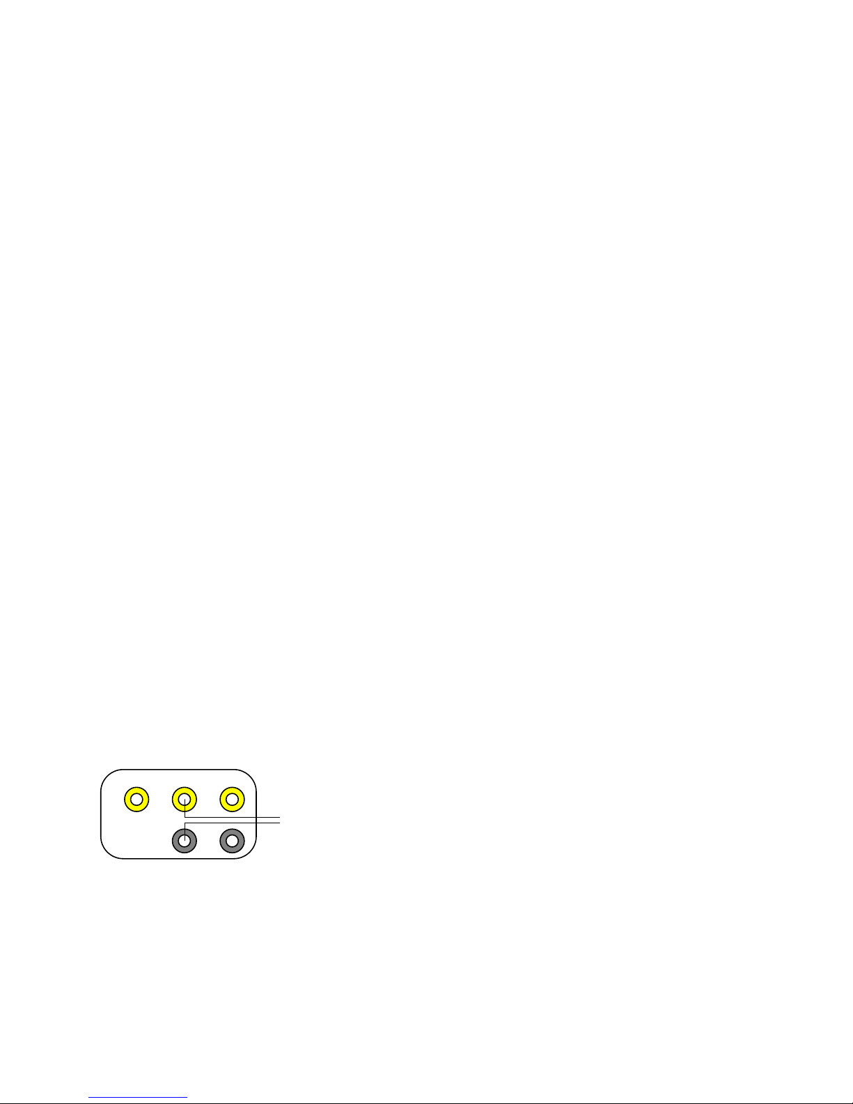
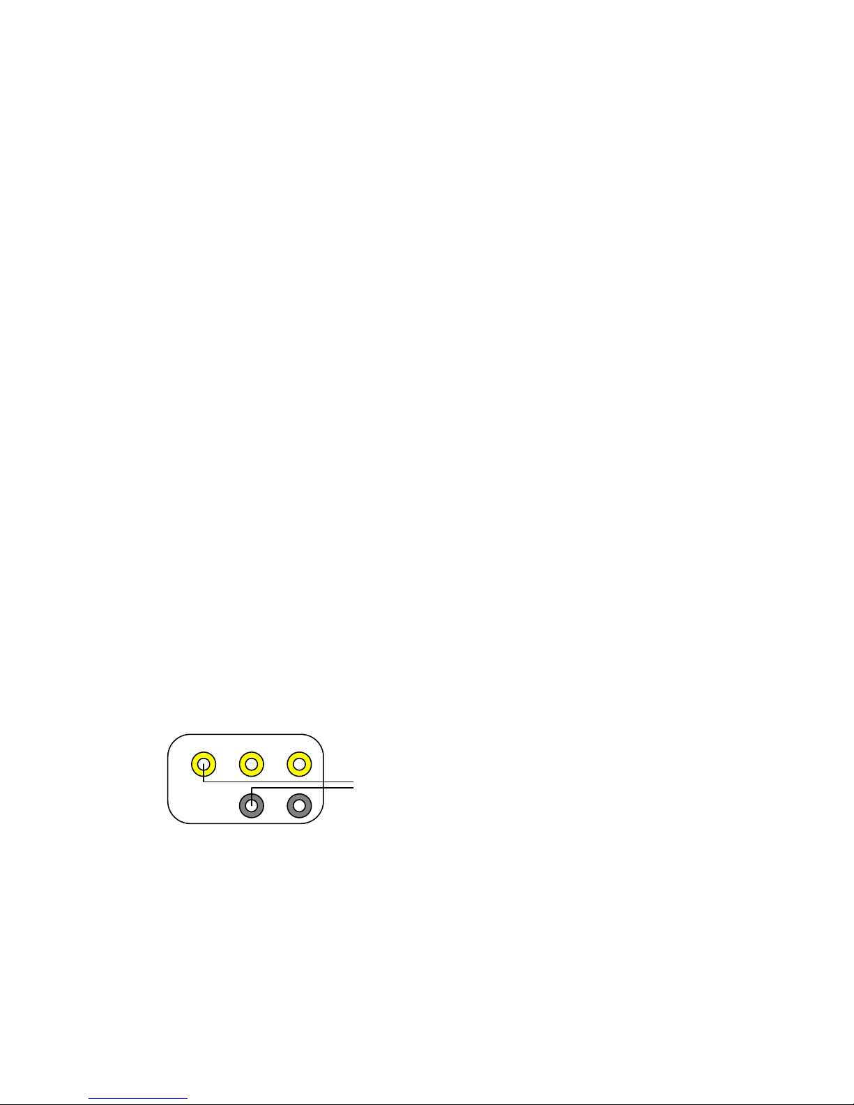
Figure: Connection of measurement leads in Voltage Measurement
The rear plugs are connected correspondingly.
For model 5017SC with scanner the measurement leads are connected to Hi and Lo of
the respective channel.
HI HI
Amps
V
Ω
Ω4
Sense
LO
+
__
DC or AC Voltage
Page 24
3 Quick Start
_____________________________________________________________________________________________________________________________________
3-3
3.4 Measuring Current
Measurement Functions
DC Current
IDC
key
AC Current
IAC
key
AC Current with DC Component
IAC
key and
COUPL
key
Measurement Ranges
Idc 200 µA, 2 mA, 20 mA, 200 mA, 2 A
Iac 200 µA, 2 mA, 20 mA, 200 mA, 2 A
Resolution and Measurement Times
Idc 20 / 40 / 100 ms 5½ digits
0.2s to 100s 6½ digits
Iac 100 / 200 ms 5½ digits
400 ms / 1 / 2 / 4 / 10 / 20 / 40 / 100 s 6½ digits
Frequency Range Iac: 20 Hz to 5kHz
max. Resolution in the smallest range Idc: 100pA Iac: 100pA
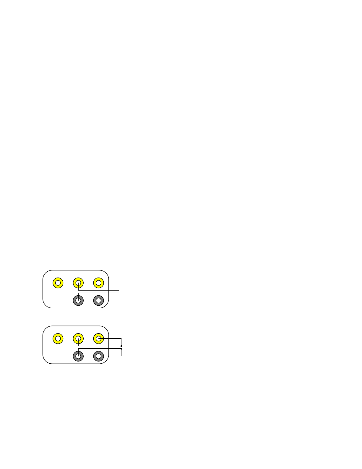
Figure: Connection of measurement leads in Current Measurement
The rear plugs are connected correspondingly.
For model 5017SC with scanner current measurement is possible only through the
front plugs.
HI HI
Amps
V
Ω
Ω4
Sense
LO
+
_
DC or AC
Current
Page 25
Measuring Resistance
_____________________________________________________________________________________________________________________________________
3-4
3.5 Measuring Resistance
Measurement Functions
2-Wire Resistance Measurement Ω2
W
key
4-Wire Resistance Measurement Ω4
W
key
Measurement Ranges
300 Ω, 3 kΩ, 30 kΩ, 300 kΩ, 3 MΩ, 30 MΩ
Measurement Times
20 / 40 / 100 ms 5½ digits
200 / 400 ms / 1s 6½ digits
2 / 4 / 10 / 20 / 40 / 100 s 7½ digits
max. Resolution in the smallest range 7½ digits, 10µ
Ω
HI HI
Amps V
Ω
Ω4
Sense
LO
Resistance
2-wire
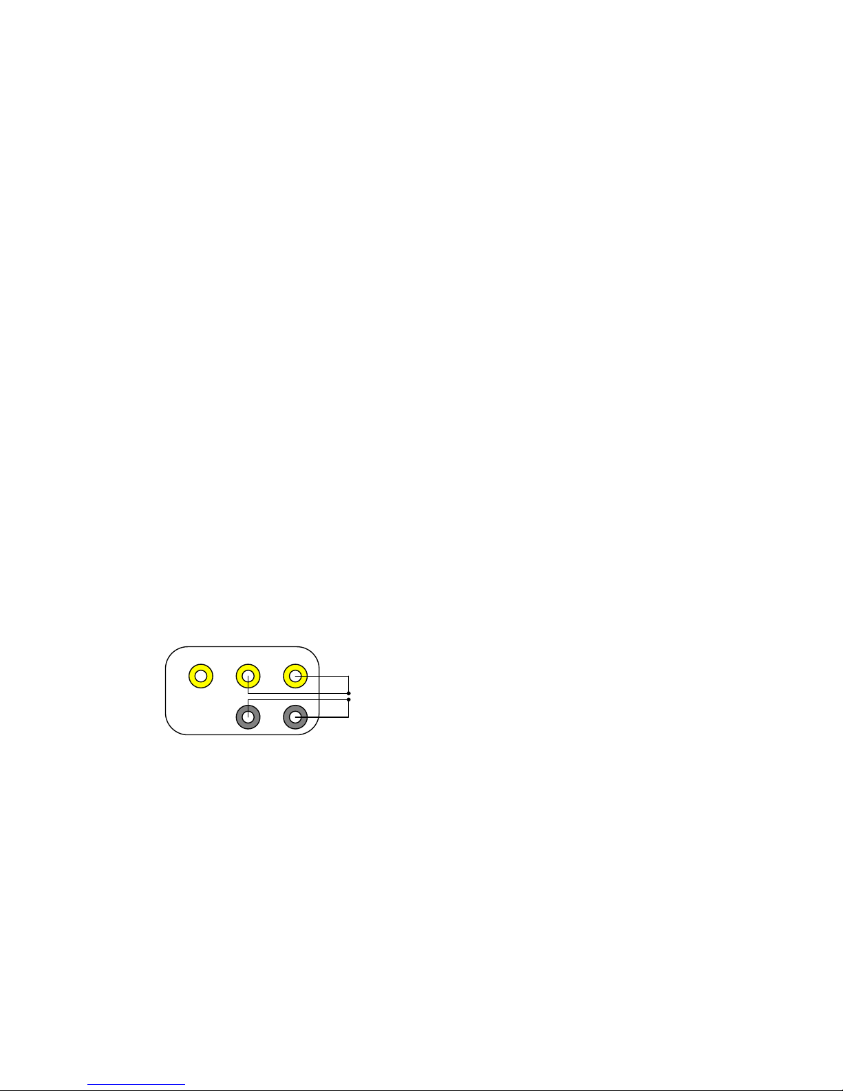
Figure: Connection of leads in resistance measurement (2-wire)
HI HI
Amps V
Ω
Ω4
Sense
LO
Resistance
4-wire
Figure: Connection of leads in resistance measurement (4-wire)
The rear plugs are connected correspondingly.
For model 5017SC with scanner the measurement leads are connected to Hi and Lo
(2-wire) or Hi, Lo (Source) and SHi, SLo (Sense) of the respective channel.
Page 26
3 Quick Start
_____________________________________________________________________________________________________________________________________
3-5
3.6 Measuring Temperature
Sensors
RTDs: Pt10, Pt25, Pt100, Pt500, Pt1000
Sensor Configuration
in the menu "Device, Temp Sensor"
Resolution and Measurement Times
0.01 K / 0.01°C / 0.01°F 100 / 200 / 400 ms
0.001 K / 0.001°C / 0.001°F 1 s to 100 s
Select °C / °F / K press
TEMP
key again
HI HI
Amps V
ΩΩ4
Sense
LO
RTD
Sensors
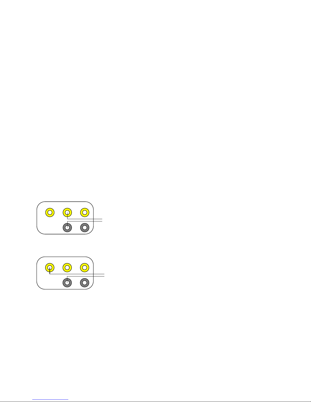
Figure: Connection of measurement leads for RTD Sensors
The rear plugs are connected correspondingly.
For model 5017SC with scanner the measurement leads are connected to Hi, Lo
(Source) and SHi, SLo (Sense) of the respective channel.
Page 27
Frequency and Period Measurement
_____________________________________________________________________________________________________________________________________
3-6
3.7 Frequency and Period Measurement
Measurement Functions
Frequency for Vac
VAC
key and
FREQ
key
Period for Vac
VAC
key and
PERIOD
key
Frequency for Iac
IAC
key and
FREQ
key
Period for Iac
IAC
key and
PERIOD
key
Select first the function Vac or Iac and adapt the right measurement range. Then select the frequency function.
Time Base 10ms / 100ms / 1s / 10s
Resolution
Frequency 1 Hz, max. 7½ digits, max. frequency 1MHz
Period Vac: 40µs to 5s / Iac: 100µs to 5s
Figure: Connection of Leads in Freq. Meas. of a Voltage
Figure: Connection of Meas. Leads in Freq. Meas. of a Current
The rear plugs are connected correspondingly.
For model 5017SC with scanner the measurement leads are connected to Hi and Lo
(Voltage) of the respective channel.
Frequency measurement of a current is only possible through the front plugs.
HI HI
Amps V
ΩΩ4
Sense
LO
+
__
with Voltage
Frequency and Period
Measurement
HI HI
Amps V
ΩΩ4
Sense
LO
+_Frequency and Period
Measurement
with Current
Page 28

3 Quick Start
_____________________________________________________________________________________________________________________________________
3-7
3.8 Continuity Test
The continuity test can be selected with the
CONT KEY
.
Continuity Test Activate loudspeaker at 50Ω
Display: open or close
3.9 Selecting Measurement Ranges
The measurement range can be changed with the
Ø key and the × key. The 2
ND
-
AUTO KEY
key is used to automatically pre-select a measurement range (2nd +
MenuOut key). The “AUTO” indication then appears in the status display.
If the measurement range is set manually, and a measurement signal is too large for
that range, “Overflow” will be indicated on the display.
If automatic ranging is on, a higher measurement range is automatically selected
when a display of about 190 000 *) digits is reached. A lower measurement range is
selected when a reading of lower than about 10 000 *) is reached.
Automatic range switching occurs within <5ms.
Note: The measurement range and the integration time are stored for every
measurement function.
*) for 5-½ digit display
Page 29
Setting the Integration Time / Resolution
_____________________________________________________________________________________________________________________________________
3-8
3.10 Setting the Integration Time / Resolution
The integration time (and consequently the resolution) can be changed with the
TIME
KEY
and the cursor keys. The ×
KEY
increases the integration time, the Ø
KEY
de-
creases the integration time.
Integration Time Resolution
20ms, 40ms, 100ms 5½ Digits
200ms, 400ms, 1s 6½ Digits
2s to 100s 7½ Digits *)
*) for Vdc and
Ω
Table: Integration Times and Resolutions
Note: Range and Integration Time are stored for the respective measurement
function.
Page 30
3 Quick Start
_____________________________________________________________________________________________________________________________________
3-9
3.11 Display
The display can be changed and configured in the menu "Device, Display",
format.
Display with Settings
Figure: Display with Settings
Selecting with Menu "Device, Display, Settings".
Meaning of the Settings
Settings Bedeutung
REAR Rear inputs are active
MATH Mathematic program is active
FILT Filter is switched on
REM Device is in remote mode
AUTO Auto Ranging is switched on
TRIG Device is in trigger mode
STORE not used
ADR Device is in talker / listener mode
Table: Meaning of the Settings
REAR
MATH FILT REM
9 ÞÞßß
AUTO
TRIG STORE ADR
Page 31
Display
_____________________________________________________________________________________________________________________________________
3-10
Display with Mathematics
Figure: Display with Mathematics
Selection with "Menu Device, Display, Math".
Abbreviation Meaning
OFS Offset x - a
LIN Linearization ax + b
RTO Ratio x / a
DEV % Deviation 100 * (x - a) / a
dB dB
dBm dBm
Table: Meaning of the Mathematics Abbreviations
Display with Channel
Figure: Display with Channels
Selection with Menu "Device, Display, Channel".
REAR
MATH FILT REM
9 2)6
AUTO
TRIG STORE ADR
REAR
MATH FILT REM
9 &
AUTO
TRIG STORE ADR
Page 32

3 Quick Start
_____________________________________________________________________________________________________________________________________
3-11
The last two digits in the display show the channel number.
Display with Time Counter
Figure: Display with Time Counter
Selection with "Menu Device, Display, Sec Counter".
The last two digits are counting the seconds for measurement times of more than 2s.
REAR
MATH FILT REM
9 7
AUTO
TRIG STORE ADR
Page 33

Display
_____________________________________________________________________________________________________________________________________
3-12
Page 34
4 Manual Operation
_____________________________________________________________________________________________________________________________________
4-1
4 Manual Operation
4.1 Keypad
The user friendly design of the front panel permits quick and effective working with
this instrument. On the one hand the keyboard provides direct access to important
functions of the instrument such as measuring function and range setting, preselection
of the measuring time and activation of a mathematical program. On the other hand,
more complex settings can easily be made with the cursor and menu control.
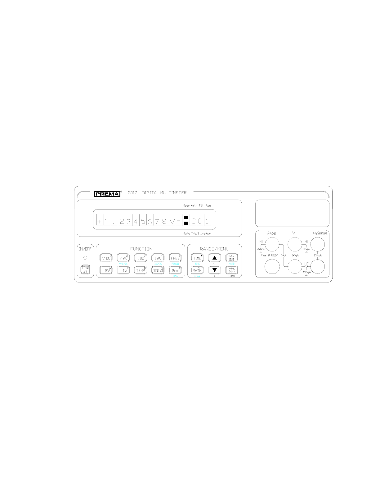
Blue legend is present under some of the keys. The functions corresponding to this
legend are activated after first pressing the 2nd key (second function key).
Apart from the normal function assignment, some keys have a numerical second
assignment. This second assignment is activated when it is necessary to make
numerical entries, for example in the mathematical programs or for calibration.
Front view of the 5017
Page 35
Keypad
_____________________________________________________________________________________________________________________________________
4-2
The Function Field
KEY Key function
ON/OFF (Standby) Switches the processor section of the instrument on and off.
In standby mode the analog electronic circuits are still powered up,
i.e. the instrument is ready sooner for operation with full
accuracy after switch-on.
VDC Direct voltage measurement (numerical: 1)
VAC Alternating voltage measurement as true RMS without DV component
(numerical: 2).
VAC+DC
(2nd + VAC)
Alternating voltage measurement as true RMS with DV component.
IDC Direct current measurement (numerical: 3).
IAC Alternating current measurement as true RMS without DC component.
(numerical: 4).
IAC+DC
(2nd + IAC)
Alternating current measurement as true RMS with DC component.
FREQ Frequency measurement for Vac and Iac (numerical: 5).
PERIOD
(2nd + FREQ)
Period duration measurement for Vac and Iac.
Ω
2W
2-wire resistance measurement (numerical: 6).
Ω
4W
4-wire resistance measurement (numerical: 7).
TEMP Temperature measurement with a preselected sensor,
repeated pressing of this key cycles through °C, °F and Kelvin
(numerical: 8).
CONT Continuity testing
2nd Switches over for the blue legend under the keys.
TRIG (2 x 2nd) Executes a manual trigger.
Table: The keys in the function field
Page 36
4 Manual Operation
_____________________________________________________________________________________________________________________________________
4-3
The Range / Menu Field
KEY Key function
TIME The measuring time and thus the resolution can be changed in conjunction
with the cursor keys (numerical: Dot).
ZERO
(2nd + TIME)
Starts an offset correction (zero point adjustment).
MATH Activates and deactivates calculation mode of the instrument with the preset
mathematical program (numerical: "+/-").
CHAN
(2nd + MATH)
Selects a measuring channel.
Implemented only in instruments with built-in measuring point scanner.
×
Switches to the next higher measuring range. Automatic range switching is
deactivated. The cursor keys control the entry within the operating menus.
Ø
Switches to the next lower measuring range. Automatic range switching is
deactivated. The cursor keys control the entry within the operating menus.
Menu OUT Switches back one menu level.
AUTO
(2nd + Menu OUT)
Activates automatic range switching (autoranging).
Menu IN
↵
Activates menu control, press Enter to confirm,
or switches one menu level deeper.
LOCAL
(Menu IN ↵)
When in remote control mode, pressing this key
switches the instrument to local mode.
Table: The keys in the Range / Menu field
Page 37
The Display Field
_____________________________________________________________________________________________________________________________________
4-4
4.2 The Display Field
The alphanumeric liquid crystal display (LCD) shows the measurement reading, the
measuring unit and a status display (or the currently active channel or the set
measuring time).
Display Elements
1 to 10 Used to display the 5½- to 7½ digit measurement reading or
calculation result with sign, or error messages.
11 to 12 Used to display the selected measuring function.
13 REAR for input sockets activated on the rear panel
AUTO for autoranging ON
14 MATH for mathematical functions ON
TRIG for trigger mode ON
15 FILT for filter ON
REAR
MATH FILT REM
9 ÞÞßß
AUTO TRIG
STORE ADR
Display Measuring function
V / mV Direct voltage
V~ / mV~ Alternating voltage
V=~ / mV=~ Alternating voltage with
direct voltage component
A / mA Direct current
A~ / mA Alternating current
A=~ / mA Alternating current with
direct current component
Hz Frequency
s Period duration
°C, K, °F Temperature
Page 38

4 Manual Operation
_____________________________________________________________________________________________________________________________________
4-5
STORE not used
16 REM for remote control ON
ADR for device mode as Talker or Listener
or
14 to 16 Channel number display when "Channel" has been chosen in
menu "Device, Display". Is active only when the
measuring points scanner is activated.
or
14 to 16 Mathematical display when "Math" has been chosen in menu
"Device, Display". Is active only when mathematical functions
are . selected.
or
14 to 16 Seconds counter when "Sec-Counter" has been chosen in menu
"Device, Display". The seconds counter is active only when the
measuring time is 4 seconds or longer.
Further information on the display is contained in the chapter headed "Quick Start".
4.3 Measuring Inputs
For connecting the measuring signals, the 5017 is equipped on the front panel and
optionally on the rear panel with low thermoelectric EMF safety sockets for banana
plugs.
With the 5017SC with built-in measuring points scanner, switchover to the scanner
inputs is possible internally in the instrument.
Read chapter ‘Getting Started’ headed "Connection of Measurement Leads" for the
instructions for switching over to the inputs on the rear of the instrument.
Connecting the Measuring Cables
Page 39
Measuring Inputs
_____________________________________________________________________________________________________________________________________
4-6
The signal which is to be measured should always be connected in such a way that the
lead closest to ground potential is connected to the black input socket (LO) and the
line with the higher potential is connected to the red input socket (HI). The display
then shows a reading with positive sign.
Please read chapter ‘Getting Started’, "Connection of Measurement Leads" for
connecting the measuring cables for each measuring function.
The pinout of the measuring inputs of the measuring points scanner is specified in the
chapter "Technical Specifications".
Limiting Data for the Measuring Inputs
The stipulated limiting data must be observed when connecting signals to be
measured. These limiting data are stated in red legend on the front panel adjacent to
the corresponding input connectors (Vpk means peak volts).
Measuring Input Front or Rear Sockets Measuring Points Scanner
V Ω- Hi-Lo
1000 Vpk 125 Vpk
Lo-Ground 250 Vpk 125 Vpk
Sense Hi-Lo 250 Vpk 125 Vpk
Sense Lo-Ground 250 Vpk 125 Vpk
Table: Limiting data for the measuring inputs
Page 40
4 Manual Operation
_____________________________________________________________________________________________________________________________________
4-7
4.4 Setting the Measuring Functions
All measuring functions are selected with a single keystroke. Period duration,
Vac+dc and Iac+dc must be activated by first pressing the 2
ND KEY
. The selected
measuring function appears in the display immediately after pressing the key. The
first reading is displayed after elapse of the set integration time plus an internal
waiting time.
4.5 Measuring Range Selection
The measuring ranges can be set in fixed manner or they can be selected
automatically by the instrument. Automatic selection is made with the AUTO
function (2nd +
MENU OUT
KEY).
The Ø-KEY switches to the next lower range. The ×-KEY switches to the next
higher range. The position of the decimal point indicates the currently selected
measuring range.
The following table gives an overview of the measuring ranges which can be set.
Range Function Range Function Range Function
300 mV Voltage
300
Ω
Resistance 200 µA Current
3 V Voltage
3 k
Ω
Resistance 2 mA Current
30 V Voltage
30 k
Ω
Resistance 20 mA Current
300 V Voltage
300 k
Ω
Resistance 200 mA Current
700 / 1000 V Voltage
3 M
Ω
Resistance 2 A Current
30 M
Ω
Resistance
Table: Ranges which can be set
Page 41
Channel Selection for 5017SC
_____________________________________________________________________________________________________________________________________
4-8
4.6 Channel Selection for 5017SC
The channels of the built-in measuring points scanner can be selected in two ways:
1st possibility
Keypress Display / Action
CHAN: 2
ND
+ MATH
ÇÈ
&KDQQHO
×
-
KEY
increases the channel number by one
Ø
-
KEY
decreases the channel number by one
MENU-OUT KEY
terminates the entry and switches on the desired channel
Table: Channel selection with cursor keys
2nd possibility
Keypress Display / Action
CHAN: 2 nd + MATH
ÇÈ
&KDQQHO
MENU-IN KEY
ÇÈ
&KDQQHO
permits numerical entry for the channel marked by the cursor, using the
numerical keys in the function field
×
-
KEY
Cursor to left (tens digit)
Ø
-
KEY
Cursor to right (units digit)
MENU-IN KEY
confirms the entry
MENU-OUT KEY
terminates the entry and switches on the desired channel
Table: Channel selection by direct numerical entry
Function, range and integration time are stored for every channel and remain valid
after channel switching.
Page 42
4 Manual Operation
_____________________________________________________________________________________________________________________________________
4-9
4.7 Offset Correction
An offset value produced by thermoelectric EMFs or by the resistance of the
measuring leads can be corrected digitally with the "ZERO" (2nd +
TIME
) -KEY.
Further details for this function are given in chapters "Calibration" and "Operating
Instructions".
4.8 Navigating in the Menu Structure
The first menu level is designated by upper case letters. Two dots appear if there are
any deeper menu levels.
Manual control of the menus is as follows:
Keypress Display / Action
MENU-IN KEY
activates menu control
×
-
KEY
switches to the previous menu item on the same level
Ø
-
KEY
switches to the next menu item on the same level
MENU-IN KEY
Selects the desired menu item,
steps down one menu level deeper or activates an item on the previous
menu level.
MENU-OUT KEY
Terminates the entry and takes over the settings made
Then steps up one menu level higher
During numerical entry, takeover of the former settings
Table: General menu control
Page 43

Navigating in the Menu Structure
_____________________________________________________________________________________________________________________________________
4-10
The structure of the menu is described in the following table:
1 MATHEMATICS 2 CONFIGURE 3 DEVICE
1*Offset
Ofs=x-a
a=+0.0000000E+0
2 ax+b
Lin = ax + b
a=+0.0000000E+0
b=+0.0000000E+0
3 Ratio
Rto = x / a
a=+0.0000000E+0
4 %Deviation
Dev=100(x-a)/a
a=+0.0000000E+0
5 dB ..
6 dBm
1 Start Mode
2 Filter
1*Auto Filter
2 Fast Auto Filt
3 Avrg Filt
3 Settings
1 Save Settings
2 Load Fact. Set
4 Calibration
1 Enter Value
2 Store Cal.
3 Load Cal.
4 Load Fact. Cal
1 Contrast N
2 Interface 1 IEEE-488
1 Address
2 * RS233
1 Xon/Xoff
2 RTS / CTS
3* no Handshake
3. Command Set
1. 5017
2. 6048 / 6047
3. 6001 / 5001 / 4001
3 Temp Sensor 1 Pt10 2 Pt25 3* Pt100
4 Pt500 5 Pt1000
4* Beeper
5 Display 1*Settings
2 Math
3 Channel
4 Sec Counter
6 Scanner 1* 4-pole, 20 CH
2 2-pole, 40 CH
3 1-pole, 80 CH
Table: Menu structure
The ‘*’ sign means that this menu item is activated.
Page 44

4 Manual Operation
_____________________________________________________________________________________________________________________________________
4-11
4.9 Mathematical Programs
The mathematical programs are used to convert the displayed measurement reading
according to a specified formula.
Selection / Manual Control
The manual control procedure is as follows:
Keypress Display / Action
1.
MENU-IN KEY
0$7+(0$7,&6
If this display does not appear, press the ×-
KEY
until it appears.
2.
MENU-IN KEY
D[E
The asterisk means that this program is selected.
3.
Ø
-
KEY
/ ×-
KEY
Press repeatedly until the desired mathematical program appears in
the display.
4.
MENU-IN KEY
/LQ D[E
Describes the conversion formula of the program
(or press the
Ø×
KEYS
until the formula appears)
5.
Ø
-
KEY
D (
Switches to input mode for the constant
6.
MENU-IN KEY
D (
Numerical entry possible. The digit is selected with theØ×-
KEYS
(see blue legend)
7.
MENU-OUT KEY
Terminates the entry without takeover of the number entered.
8.
MENU-IN KEY
Takes over the entry.
9.
Ø
-
KEY
Selects further constants, if any.
10.
MENU-OUT KEY
Steps up one menu level higher.
11.
MATH KEY
Activates / deactivates the previously
selected mathematical program.
Table: Selecting a mathematical program
The input of the constants have to be in the displayed unit and not in the physical unit.
For example you want to calculate in the resistance measurement, range 3 kΩ and the
constant is ‘5000.000’ please enter 5.000.
Page 45
Mathematical Programs
_____________________________________________________________________________________________________________________________________
4-12
Meaning of the Mathematical Programs
Mathematical Program Conversion Meaning
1 Offset (Ofs) Display = x - a Subtraction of a constant
2 ax+b (Lin) Display = ax + b Linearization of the measuring range
3 Ratio (Rto) Display = x / a Ratio display
4 %Deviation (Dev) Display = 100 (x - a) / a Percentage deviation of the measurement
reading from a constant
5 dB .. Display = 20 log (x/a) Ratio of the measurement to a constant
voltage (current) a in decibels
6 dBm Display = 20 log (x/e)
e= 0.775V or 1.29 mA
Ratio of the measurement to a voltage
(current) corresponding to 1mW into a load
impedance of 600
Ω
Table: Meaning of the mathematical programs
Page 46
4 Manual Operation
_____________________________________________________________________________________________________________________________________
4-13
4.10 The Menu "Configure"
Start Mode / Trigger Mode
This menu activates start mode. Triggering can be performed manually or via the
external trigger socket.
Keypress Display / Action
1.
MENU-IN KEY
&21),*85(
If this display does not appear, press the ×-
KEY
until it appears.
2.
MENU-IN KEY
6WDUW0RGH
3.
MENU-IN KEY
6WDUW0RGH
activates / deactivates start mode.
4.
MENU-OUT KEY
Takes over the entry and steps up one menu level higher; press
repeatedly to reach the measurement display
5. TRIG: 2 X 2ND-K
EY
Measurement of a value is started manually
Table: Selecting start mode
Filter
To increase disturbance suppression for better stability of the measurement readings,
the input signals can be passed through a digital filter which operates as moving
average filter for the last ten readings. After the first ten readings have come into the
filter loop, each new reading thereafter replaces the oldest one.
Two filters are available:
• Automatic average value filter (Auto Filter)
• Fast Automatic average value filter (Fast Auto Filter)
• Moving average filter (Avg. Filter)
Page 47

The Menu "Configure"
_____________________________________________________________________________________________________________________________________
4-14
Automatic Filter (Auto Filter)
The automatic filter calculates the moving average over ten readings and
additionally the difference between the last two successive readings, comparing this
result with a difference value preset in the factory (depending on measuring range,
function and time). The filtering process is restarted when the difference exceeds the
value preset in the factory.
The filtering process also restarts when function, range or measuring time are
reselected.
Fast Automatic Filter (Fast Auto Filter)
similar to the automatic filter, but the first value after switching of channels or ranges
is more stable.
Moving Average Filter (Avg. Filter)
The moving average filter operates according to the same principle as above but
does not permit any signal-dependent restarting of the filter loop.
This filter is restarted when a function, range or measuring time is selected and after
pressing the
FILTER
KEY.
This kind of filtering achieves additional disturbance suppression by more than
20 dB.
Page 48
4 Manual Operation
_____________________________________________________________________________________________________________________________________
4-15
Filter Selection
Keypress Display / Action
1.
MENU-IN KEY
&21),*85(
If this display does not appear, press the ×-
KEY
until it does appear.
2.
MENU-IN KEY
)LOWHU
3.
MENU-IN KEY
$XWR)LOWHU
Activates / deactivates the automatic filter with the
MENU-IN KEY
.
4.
Ø
-
KEY
$YJ)LOWHU
Activates / deactivates the average value filter with the
MENU-IN KEY
.
5.
MENU-OUT KEY
Takes over the entry, then steps up one menu level higher. Press
repeatedly to reach the measurement reading display.
Table: Filter selection
Saving and Loading Instrument Settings
The menu item "Settings" permits saving of a power-up status or loading of factory
settings.
Keypress Display / Action
1.
MENU-IN KEY
&21),*85(
If this display does not appear, press the ×-
KEY
until it does appear.
2.
MENU-IN KEY
6HWWLQJV
3.
MENU-IN KEY
6DYH6HWWLQJV
Saves the present instrument settings as power-up status on
pressing the
MENU-IN KEY
.
4.
Ø
-
KEY
/RDG)DFW6HW
Loads the factory settings on pressing the
MENU-IN KEY
.
Table: Saving the instrument settings and loading factory settings
Page 49

The Menu "Configure"
_____________________________________________________________________________________________________________________________________
4-16
Power-Up Status
The following information items are saved in the power-up status:
• The measuring function for each channel
• The measuring range for each channel
• The measuring time (resolution) for each channel
• The filter setting
• The scanner mode
• The mathematical program and constants
• The temperature sensor
• The LCD contrast
The measurement range and measurement time are stored during operation for each
function, but this information is lost when switching off the instrument.
Calibration
Described in the chapter headed "Calibration".
Page 50
4 Manual Operation
_____________________________________________________________________________________________________________________________________
4-17
4.11 The Menu "Device"
Technical hardware settings such as temperature sensor, interface preselection, LCD
contrast and scanner setting are made in this menu.
Setting the Contrast
Keypress Display / Action
1.
MENU-IN KEY
'HYLFH
If this display does not appear, press the Ø-
KEY
until
it does appear.
2.
MENU-IN KEY
&RQWUDVW
If this display does not appear, press the ×-
KEY
until
it does appear.
3.
MENU-IN KEY
Switches-on entry mode.
4.
×
-
KEY
Increases the contrast by one unit.
5.
Ø
-
KEY
Decreases the contrast by one unit.
6.
MENU-OUT KEY
Takes over the entry and steps up one menu level higher. Press
repeatedly to reach the measurement reading display.
Table: Setting the contrast
The contrast can be adjusted over the range from 1 to 9 units.
Page 51
The Menu "Device"
_____________________________________________________________________________________________________________________________________
4-18
Preselecting the Interface
The 5017 is equipped with a RS232 serial data interface and the IEEE-488 interface.
The interface which is to be activated can be set in this menu.
Keypress Display / Action
1.
MENU-IN KEY
'HYLFH
If this display does not appear, press the Ø-
KEY
until
it does appear.
2.
MENU-IN KEY
,QWHUIDFH
If this display does not appear, press the ×Ø-
KEYS
until
it does appear.
3.
MENU-IN KEY
,(((
The IEEE488 interface is selected with the
MENU-IN KEY
.
4.
MENU-IN-KEY
$GGUHVV
Enter the device address and then to terminate the entry press the
MENU-IN KEY
.
5.
MENU-OUT KEY
Takes over the entry and steps up one menu level higher. Press
repeatedly to reach the measurement reading display.
Table: Setting the IEEE-488 interface
Keypress Display / Action
1.
MENU-IN KEY
'HYLFH
If this display does not appear, press the Ø-
KEY
until
it does appear.
2.
MENU-IN KEY
,QWHUIDFH
If this display does not appear, press the ×Ø-
KEYS
until
it does appear.
3.
MENU-IN KEY
56
The RS232 interface is selected with the
MENU-IN KEY
.
4.
MENU-IN KEY
;RQ;RII
Select the handshake mode and then press the
MENU-IN KEY
to
confirm.
5.
MENU-OUT KEY
Takes over the entry and steps up one menu level higher. Press
repeatedly to reach the measurement reading display.
Page 52
4 Manual Operation
_____________________________________________________________________________________________________________________________________
4-19
Table: Setting the RS232 interface
The possible handshake modes for the RS232 interface are:
• Xon / Xoff
• RTS / CTS (needs a special cable, see ‘Accessories’ No. 3017)
• no Handshake
Preselecting the Command Set for Remote Control
The 5017 can be remoted with different command sets:
• 5017
• 6048 / 6047
• 6001 / 5001 / 4001 ( 6½ digit)
Keypress Display / Action
1.
MENU-IN KEY
'HYLFH
If this display does not appear, press the Ø-
KEY
until
it does appear.
2.
MENU-IN KEY
,QWHUIDFH
If this display does not appear, press the ×Ø-
KEYS
until
it does appear.
3.
MENU-IN KEY
&RPPDQG6HW
The command set can be with the
MENU-IN KEY
.
4.
MENU-IN KEY
Select the command set and then press the
MENU-IN KEY
to confirm.
5.
MENU-OUT KEY
Takes over the entry and steps up one menu level higher. Press
repeatedly to reach the measurement reading display.
Table: Setting the command set
See chapter ‘Remote Control’ for more information.
Page 53
The Menu "Device"
_____________________________________________________________________________________________________________________________________
4-20
Selecting the Temperature Sensor
You have the choice between several different platinum resistance thermometer
sensors:
Pt10, Pt25, Pt100, Pt500, Pt1000.
Keypress Display / Action
1.
MENU-IN KEY
'HYLFH
If this display does not appear, press the Ø-
KEY
until
it does appear.
2.
MENU-IN KEY
7HPS6HQVRU
If this display does not appear, press the ×Ø-
KEYS
until
it does appear
3.
MENU-IN KEY
3W
Select the desired sensor with the ×Ø-
KEYS
.
4.
MENU-IN KEY
3W
Activates the selected sensor.
5.
MENU-OUT KEY
Takes over the entry and steps up one menu level higher. Press
repeatedly to reach the measurement reading display.
Table: Selecting the temperature sensor
Page 54
4 Manual Operation
_____________________________________________________________________________________________________________________________________
4-21
Activating the Loudspeaker
Keypress Display / Action
1.
MENU-IN KEY
'HYLFH
If this display does not appear, press the Ø-
KEY
until
it does appear.
2.
MENU-IN-KEY
%HHSHU
If this display does not appear, press the ×Ø-
KEY
until
it does appear.
3.
MENU-IN KEY
%HHSHU
The loudspeaker is now active. Every keystroke generates a BEEP.
Proceed the same way to deactivate the loudspeaker again.
4.
MENU-OUT KEY
Takes over the entry and steps up one menu level higher. Press
repeatedly to reach the measurement reading display.
Table: Activating the loudspeaker
Setting the Display Formats
Keypress Display / Action
1.
MENU-IN KEY
'HYLFH
If this display does not appear, press the Ø-
KEY
until
it does appear.
2.
MENU-IN KEY
'LVSOD\
If this display does not appear, press the ×Ø-
KEYS
until
it does appear.
3.
MENU-IN KEY
0DWKHPDWLFV
Select the desired display format with the ×Ø-
KEYS
.
4.
MENU-IN KEY
0DWKHPDWLFV
Activates / deactivates the selected format.
5.
MENU-OUT KEY
Takes over the entry and then steps up one menu level higher. Press
repeatedly to reach the measurement reading display.
Table: Setting the display format
Page 55
The Menu "Device"
_____________________________________________________________________________________________________________________________________
4-22
The following display formats can be selected:
1 Mathematics
Condition: Mathematical program is switched on.
2 Channel
Condition: 5017SC and internal connector plugged into scanner.
3 Sec. Counter (Measuring time counter)
Condition: Measuring time 4 s or longer
If the conditions are not fulfilled, a display with these settings is shown:
Please read chapter 3, "Quick Start" for a detailed description of the meanings of the
settings.
REAR MATH
FILT REM
9 2IV
AUTO TRIG
STORE ADR
REAR MATH
FILT REM
9 &
AUTO TRIG
STORE ADR
REAR MATH
FILT REM
9 7
AUTO TRIG
STORE ADR
REAR MATH
FILT REM
9 ÞÞßß
AUTO TRIG
STORE ADR
Page 56
4 Manual Operation
_____________________________________________________________________________________________________________________________________
4-23
Setting the Scanner Mode
Keypress Display / Action
1.
MENU-IN KEY
'HYLFH
If this display does not appear, press the Ø-
KEY
until
it does appear.
2.
MENU-IN KEY
6FDQQHU
If this display does not appear, press the ×Ø-
KEYS
until
it does appear.
3.
MENU-IN KEY
SROH&+
Select the desired mode with the ×Ø-
KEYS
.
4.
MENU-IN KEY
SROH&+
Activates the selected mode.
5.
MENU-OUT KEY
Takes over the entry and then steps up one menu level higher. Press
repeatedly to reach the measurement reading display.
Table: Setting the scanner mode
The following scanner modes can be set:
• 4-pole, 20 channels
• 2-pole, 40 channels
• 1-pole, 80 channels
The pinout of the 50-pole Sub-D plug connector of the measuring points scanner is
contained in chapter "Technical Specifications".
Page 57

Error Messages
_____________________________________________________________________________________________________________________________________
4-24
4.12 Error Messages
Overflow Measuring range overflow
Sensor? Resistance of the sensor overshoots/undershoots the
defined range
Div/0 Division by zero in a mathematical function
Br. wires Open source line in 4-wire resistance measurement
Offset too high Offset too large after pressing the zero key
Polarity? Ω/4: Source or Sense are not connected with the right
polarity
Cal. Error Calibration error
reading too low Measurement reading too small
value too low Value too small
value too high Value too large
not mathematics Not for mathematics
not temperature Not for temperature measurement
Scanner Mode? Scanner mode unsuitable
Front Input Only Only at front sockets (e.g. current measurement)
invalid PIN Invalid PIN number for calibration
Page 58

5 Remote Control
_____________________________________________________________________________________________________________________________________
5-1
5 Remote Control
This chapter describes operation of the 5017 via the IEEE-488 and RS232 interface in
remotely controlled measuring systems.
This instrument supports both interface types: IEEE-488 and RS232
5.1 Configuration
Some manual configurations must be made to enable operation of the 5017 via one of
the two interfaces IEEE-488 or RS232.
All necessary settings are made in the menu "Device, Interface".
• Select interface (RS232, IEEE-488)
• Assign device address for IEEE-488
• Set handshake mode for RS232
• Set the command set (standard is ‘5017’)
Select Interface
Select the interface with which the instrument is to be controlled in the menu "Device,
Interface" (see chapter "Manual Operation").
The 5017 is equipped in the standard version with the two most common interfaces
used in measuring systems, namely IEEE-488 and RS232.
Configuring the RS232 Interface
Transmission via the RS232 interface takes place with 8N1 format, i.e. a data word
has 8 bits, no parity bit and one stop bit. The transmission speed is fixed at 9600 Bd.
Handshake Mode
The 5017 permits setting of various handshake modes so that this instrument can
communicate with numerous RS232 control programs. Many programing languages
and the Windows terminal program use XON/XOFF handshake. A special RS232
cable (zero modem cable, see chapter ‘Accessories’ No. 3017) is required for
RTS/CTS handshake, but very fast and reliable data transmission is possible then.
Page 59

Configuration
_____________________________________________________________________________________________________________________________________
5-2
End Detection under RS232
The end of a transmitted or received message is designated with a line feed character
"LF" in RS232 data transmission.
Configuring the IEEE-488 Interface
The device address and the terminator character of the messages (ASCII strings) are
of importance for programing and data transmission in communication between the
control computer and the 5017. The IEEE address can be assigned by the user, but the
terminator is fixed and defined by the 488.2 standard.
Setting the IEEE-488, Device Address
The device address is set via the menu "Device, Interface, IEEE488" (see chapter
"Manual Operation") and can be saved in the power-up status.
The device address set in the factory is 7.
End Detection in the IEEE-488, Message Transmission
When operating with the IEEE488 interface, the standard string terminators are used
for reception and transmission of messages (ASCII strings), namely "LF+EOI". "LF"
stands for "Line Feed" and "EOI" designates an interface line which is set by
hardware control.
Define the Command Set
Different command sets can be selected. In this way the 5017 can replace the DMMs
6047/6048 and 6001/5001/4001 and work with the same software.
Please chapter ‘Compatibility’ for special remarks and restrictions of the
compatibility.
Page 60

5 Remote Control
_____________________________________________________________________________________________________________________________________
5-3
5.2 General Information concerning Remote Control
All functions which can be manually controlled via the keyboard can also be remotely
controlled, except for the device address assignment which can only be set via the
keyboard.
As soon as the instrument has received the first command via the interface, the
keyboard is disabled for manual control of the instrument functions. Manual control
via the keyboard is thereafter possible again after pressing the
LOCAL-BUTTON
.
In remote control mode the designator “Rem" is lit in the right window of the main
display.
The instrument understands up to 30 characters in a command. All characters are
ASCII characters. Several commands can be combined in and executed from a single
string of characters sent as one message (e.g. "VDR5A1"), but some commands must
be sent at the end of a string, as ‘NVxxxxxxxxx’, ‘Cnx’, ‘Slx’, ‘D1...’ and the ‘?commands’.
The specific commands for controlling data transmission via the interface are
contained in the manual for the utilized IEEE bus interface and some are specific to
the programing language used.
Any space characters (SPACE, ASCII code 20H) contained in the character string
sent by the computer are ignored.
The instrument can receive commands (operation as LISTENER) and it can also send
device messages concerning its status (operation as TALKER). In this status the
indication "ADR" appears on the very right in the display.
The time when the instrument transmits messages can be defined by the computer.
One possibility is for the computer to address the instrument as TALKER, and then
read-out the device message. The second possibility is to operate the instrument in
SRQ (service request) mode. It then requests service from the computer when a status
change has taken place. Switchover to SRQ mode can be made with a command. The
basic status of the instrument after power-up is without SRQ
5.3 Special Features for the RS232 Interface
The DMM 5017 is directly sending measurement values when opening the RS232
interface. If this is not wanted, the command ‘CN0’ can be send from the PC. Then
the instrument sends only a measurement value, if ‘RD?’ comes from the PC.
Page 61

Capabilities of the IEEE-488 Bus Interface
_____________________________________________________________________________________________________________________________________
5-4
5.4 Capabilities of the IEEE-488 Bus Interface
The IEEE computer interface has the following capabilities defined by the IEEE-488
standard:
SH 1 Handshake source function
AH 1 Handshake sink function
T6 TALKER function
L3 LISTENER function
RL1 Remote control
DC1 Reset function
DT1 Initiate function
SR1 Service request function
General IEEE-488.1 Messages
The instrument understands the universal commands DCL, SPE and SPD. The
command DCL (device clear) brings the instrument into its basic state (V dc, 300V).
Of the addressed commands it understands GET, GTL, LLO and SDC.
The commands have the following effects:
DCL Device Clear Sets the instrument to the basic state
SDC Selected Device Clear Sets the instrument to the basic state
GTL Go To Local Terminates remote control status
LLO Local Lock Out The instrument cannot be switched to manual
control via the local button (keyboard lockout)
SPE Serial Poll Enable Prepares for serial polling
SPD Serial Poll Disable Terminates serial polling
GET Group Execute Trigger Initiates a trigger for the addressed devices
UNT UnTalk Addressing cancellation - is not displayed
UNL UnListen Addressing - is not displayed
PPC, PPU, TCT not supported
Page 62

5 Remote Control
_____________________________________________________________________________________________________________________________________
5-5
5.5 RS232 / IEEE-488.2 Common Commands
In addition to the 488.1 commands, the 5017 also understands common commands
according to the IEEE-488.2 standard that can be used with both interfaces RS232
and IEEE-488.
The common commands are transmitted to the 5017 as ASCII character string which
must always start with an asterisk "*".
The following commands are implemented in the 5017:
*CLS Clear Status Byte (command)
*ESE Standard Event Status Enable (command)
*ESE? Standard Event Status Enable (query)
*ESR? Standard Event Status Register (query)
*IDN? Identification (query)
*OPC Operation Completed (command)
*OPC? Operation Completed (query)
*RST Reset (command)
*SRE Service Request Enable (command)
*SRE? Service Request Enable (query)
*STB? Read Status Byte (query) see description
*TST? Self Test (query)
*WAI Wait To Continue (command)
*CLS, Clear Status Command
The command "*CLS" resets the status byte and the error queue. The Enable, Event,
ESE and SRE registers are not reset.
Page 63

RS232 / IEEE-488.2 Common Commands
_____________________________________________________________________________________________________________________________________
5-6
*ESE Standard Event Status Enable Command
The command "*ESE <Number> " sets the contents of the Standard Event Enable
Register (event register mask). The parameters thereby have no effect.
Number Meaning for the Standard Event Enable Register
0 Resets the register
1 (Bit 1) Service Request
2 (Bit 0) Operation Completed (OPC) is set
4 (Bit 2) Query Error (QYE) is set
8 (Bit 3) Device Dependent Error (DDE) is set
16 (Bit 4) Execution Error (EXE) is set
32 (Bit 5) Command Error (CME) is set
64 (Bit 6) User Request (URQ) is set
128 (Bit 7) Power On (PON) is set
*ESE? Standard Event Status Enable Query
The command "*ESE?" reads out the mask set in the Standard Event Enable
Register.
The reply is a decimal value whose binary meaning is as stated above.
*ESR? Standard Event Status Register Query
The command "*ESR?" reads the current contents of the Standard Event Status
Register. The contents of this register are written directly by the instrument according
to a certain event. After read-out this register is reset to 0.
Page 64

5 Remote Control
_____________________________________________________________________________________________________________________________________
5-7
*IDN? Identification Query
The command "*IDN?" queries the identification designation of the 5017. Read-out
produces a character string with the following format:
"PREMA GmbH,5017 DIGITAL MULTIMETER,0,<year>-<week>-<Number>"
with <year> = Year of software version
<week> = Week of software version
<Number> = No. of software version
For example:
"PREMA GmbH,5017 DIGITAL MULTIMETER,0,97-10-01"
*OPC Operation Completed Command
The command "*OPC" sets the Operation Completed bit (Bit 0) of the Standard
Event Status Register after all currently running command sequences have been
executed completely.
*OPC? Operation Completed Query
The command "*OPC?" makes the instrument write an ASCII 1 into the output buffer
if all currently running operations have been completed.
*RST Reset Command
The command "*RST" executes a reset of the 5017. The instrument thereby takes the
default setting (*RST). All still running internal operations are aborted, but no
registers are reset.
Page 65

RS232 / IEEE-488.2 Common Commands
_____________________________________________________________________________________________________________________________________
5-8
*SRE Service Request Enable Command
The command "*SRE <Number>" sets the mask for the Service Request Enable
Register. The individual numbers here have the following meaning:
Decimal value Contents of the Service Request Enable Register
0 Resets the register.
1 (Bit 0), sets measurement value
2 (Bit 1), sets Error message like "Overflow", "Sensor?", "Div/0"
4 (Bit 2), sets Error Available (EAV)
16 (Bit 4), sets Message Available (MAV).
32 (Bit 5), sets Event Summary Bit (ESB).
128 (Bit 7), sets button pressed
Bit 3 and 6 are not assigned.
*SRE? Service Request Enable Query
The command "*SRE?" reads the contents of the Service Request Enable Register.
The meaning of the contents of this register is as described above for the *SRE
command.
*STB? Read Status Byte Query
The command "*STB?" reads out the status byte of the 5017. The value of the Status
Byte is always 0, because the measurement value is set back after a new command.
Use SRQ if you want to check when a maeasurement value is available.
Decimal value Meaning in the status byte register
1 (Bit 0), Measurement Value available
2 (Bit 1), Error like "Overflow", "Sensor?", "Div/0" occured
4 (Bit 2), Error Queue.
16 (Bit 4), Message Queue.
32 (Bit 5), Event Summary Bit (ESB).
64 (Bit 6), Master Summary Status (MSS)/ Request Service (RQS)
128 (Bit 7), Button pressed
Page 66

5 Remote Control
_____________________________________________________________________________________________________________________________________
5-9
Bit 3 is not assigned.
To determine exactly what events have taken place, query the corresponding status
registers.For example, if Bit 5 (ESB) is set, the cause can be determined with the
command"*ESR?".
For the IEEE488 interface, setting of Bit 6 activates the SRQ line so that the
controller card in the computer can respond.
*TST? Self Test Query
The command "*TST?" interrogates the result of the power-up self test of the
instrument. The reply is “0“ is the self test was completed without error. If any other
value is obtained, please contact PREMA GmbH.
*WAI Wait-to-Continue Command
The command "*WAI" prevents execution of further commands until the operations
of a previous command have been completed.
Page 67
Structure of the Registers
_____________________________________________________________________________________________________________________________________
5-10
5.6 Structure of the Registers
&
&
&
&
&
&
&
&
Standard Event Register
OPCOperation com plete
Execution error
Command error
Query error
User request
Power on
not used
Device dependent error
QYE
DDE
EXE
CME
URQ
1
PON
*ESR?
Status
0
&
Meas
6
5
1
2
3
4
OR
7
*ESE
*ESE?
7
Output queue
IEEE488.2
&
&
&
&
&
&
&
Error
MAV
3
EAV
Button
*STB?
ESB
RQS/MSS
Status
Enable
Error/event queue
SCPI
(Set of SRQ)
Status Byte
Meas
Enable
Error
MAV
ESB
3
EAV
6
Button
*SRE
*SRE?
OR
Service Request
Page 68

5 Remote Control
_____________________________________________________________________________________________________________________________________
5-11
5.7 Operation as Listener
The instrument must be addressed as LISTENER to prepare it for receiving
commands. The instructions for doing this are contained in the user manual of the
computer manufacturer. The segment ‘ADR’ in the right window of the display is lit
when the instrument has been addressed as LISTENER.
The instrument understands the following commands:
MR Measuring mode. The measurement reading is selected and appears in the
display of the digital multimeter and in the character string of the TALKER
function.
CR Calculating mode. The calculation result of the selected program appears in
the display of the digital multimeter and in the character string of the
TALKER function.
Cx Entry of constants,
Format x: Constant No., Sign, Constant value
x = 0: Constant a, x = 1: Constant b Example: C1+3.45678912E+6
Constants has to be entered in the displayed unit, not in the physical unit.
VD Direct voltage Vdc
VA Alternating voltage Vac
VC Alternating voltage + Direct voltage component Vac + dc
O2 2-wire resistance measurement Ω2W
O4 4-wire resistance measurement Ω4W
ID Direct current Idc
IA Alternating current Iac
IC Alternating current + Direct current component Iac + dc
TC Temperature measurement in °C
TF Temperature measurement in °F
Page 69

Operation as Listener
_____________________________________________________________________________________________________________________________________
5-12
TK Temperature measurement in K
SLx Selection of the temperature sensor with
x = 1 Pt10 x = 3 Pt100
x = 2 Pt25 x = 4 Pt500
x = 5 Pt1000
SL? Query of the currently set temperature sensor
FQ Frequency
PD Period duration
CO Continuity check
Pxx Program selection with
xx = 01 Offset
xx = 02 ax + b
xx = 03 Ratio
xx = 04 % Deviation
xx = 05 dB
xx = 06 dBm
A0 (A/zero) Autoranging off
A1 Switches autoranging on
Rx Measuring range selection with
x = 1 300mV, 300 Ω, 200µA
x = 2 3V, 3 kΩ, 2mA
x = 3 30V, 30 kΩ, 20 mA
x = 4 300V, 300 kΩ, 200 mA
x = 5 1000V, 3 MΩ, 2 A
x = 6 30 MΩ
Page 70

5 Remote Control
_____________________________________________________________________________________________________________________________________
5-13
Tx Integration time / Measuring time selection with
x = 0 20ms x = 6 2 s
x = 1 40ms x = 7 4 s
x = 2 100ms x = 8 10 s
x = 3 200ms x = 9 20 s
x = 4 400ms x = A 40 s
x = 5 1 s x = B 100 s
x = Z 10ms (only for frequency measurement)
D0 (D/zero) Display mode switch-off
D1“text“ Display mode switch-on. A text sent after “D1“ is output to the dis
play of the multimeter. The internal display is switched off. The
text sent must be enclosed between quote characters.
F0 (F/zero) switches off the additional filter.
F1 Switches on the average value filter (Avg. Filter).
F2 Switches on the automatic filter (Auto Filter ).
F3 Switches on the fast automatic filter (Fast Auto Filter ).
Q0 (Q/zero) switches off SRQ mode.
Q1 Switches on SRQ mode on:
- every new measurement reading
- error message
- reset
- out of limit
EQ? Query of the Error-Queue
S0 (S/zero) start mode off, continuous sequence of measurements on
S1 Start mode on; every S1 command starts a measurement
S2 Start mode on, start with trigger line or trigger button
Page 71

Display Mode
_____________________________________________________________________________________________________________________________________
5-14
L0 (L/zero) short format; the multimeter outputs only the first message unit
(measurement data and text messages).
L1 Long format; the multimeter outputs both message units (measurement
data/text messages and programing data).
ZO (Zeppelin/Otto) Offset correction on
Mxx Selects a scanner channel
with xx = 01 to 80
MPx Scanner mode with
x = 1 1-pole, 80 channels
x = 2 2-pole, 40 channels
x = 4 4-pole, 20 channels
NVxxxxxxxxx Calibration, calibration string transfer
After NV the multimeter expects a 9-digit unsigned integer decimal number
as nominal value for the calibration via the interface. A nominal value must
be transmitted alone, i.e. no other command from the table above may be
contained in the same string. The digital multimeter starts the calibration after
transmission of the nominal value.
NV“ppppppp“ Entry of the calibration 7-digit PIN number
Ix Contrast setting with x = 0 .... 9
RD? READ?, reads out the current measurement reading
(esp. used for RS232 interface)
CNx x = 0 Continuous mode off ( esp. used for RS232 interface)
x = 1 Continuous mode on
5.8 Display Mode
In display mode the computer can output text messages to the display of the
instrument irrespective of other functions of the instrument.
Display mode is switched on with D1. The ASCII characters following thereafter are
written to the display. All ASCII characters for which a segment code is defined in
the ASCII segment table are displayed. All other characters produce a blank (dark)
Page 72

5 Remote Control
_____________________________________________________________________________________________________________________________________
5-15
character position. All superfluous characters present after D1 and the output text are
ignored. If D1 "text" is sent together with other commands in the same character
string, it must be the last command in the character chain.
D0 switches display mode off again and the display according to the active operating
mode and function appears.
Page 73

String Length Selection
_____________________________________________________________________________________________________________________________________
5-16
5.9 String Length Selection
The digital multimeter can send different length messages to the computer whereby
the desired message length is selected with L0 or L1. The latest measurement reading
is returned if the computer sends the command L0. The status information is not
output in response to L0. In response to L1 the instrument sends the most recent data
including the status information.
5.10 SRQ Mode
If the digital multimeter is not to be continually interrogated by the computer but
instead the digital multimeter is to request service from the computer when a status
change has taken place, SRQ mode (service request) must be switched on with the
command Q1.
A SRQ is sent, for example, when keyboard input has been made, when error
messages appear. Utilization of SRQ mode requires that the connected computer can
recognize a SRQ and reply to it with a serial poll (see computer manual).
5.11 Operation of the Digital Multimeter as TALKER
On request by the computer, the instrument sends a message containing its present
status and the most recent measurement reading. For this purpose the computer must
address the instrument as TALKER. The instructions how to do this are contained in
the manual of the computer manufacturer. The message ‘ADR’ is lit in the right
window of the display when the instrument has been addressed as TALKER.
The transmitted message consists of a character string and a fixed terminator at the
end of each character string enabling the computer to recognize the end of the
transmission. The message consists of two message units. The first unit contains the
data of the most recent measurement reading or calculation result, and the second unit
contains data concerning the programing status. The two message units are
transmitted as complete data record. The string terminator is fixed and defined with
IEEE-488.2 standard as "LF + EOI".
The ASCII (ISO 7 bit) code is used for the transmission.
The length of the second message unit is fixed and always consists of 27 characters
plus the terminator character. The length of the first message unit is 14 characters for
output of measurement readings and calculation results.
Page 74

5 Remote Control
_____________________________________________________________________________________________________________________________________
5-17
Only the first message unit is transmitted when the short string is requested
(command “L0"). The status information (2nd message unit) is not sent in this case.
Description of the Message Record Sent
The following table gives an overview of the possible lengths of the message record
depending on the selected operating mode.
A message record consists of one (short string format) or of two (long string format)
message units, followed by a terminator character. The second message unit is called
the status information.
40 characters + terminator character
Example: +01.298764E+0MRVDP00A0R2F0T2D0S0Q0MOFB00"+ Terminator
or in short string format (13 characters)
+01.298764E+0" + Terminator
Example:
ERROR 01 MR04P00A1R6F0T2D0S0Q0MOFB00"+ Terminator
ERROR 01 + Terminator
The numbers in brackets (..) apply for the number of characters in short string format.
The measurement reading or a text message appears in the first message unit.
Text messages are ERROR x, NULL, CAL.
Character positions not required are filled with blanks.
The second message unit (status information) commences at the 14th character.
Page 75

Operation of the Digital Multimeter as TALKER
_____________________________________________________________________________________________________________________________________
5-18
Table of Device Messages sent by the Multimeter
The device message outputs the following characters to designate the instrument
status or the instrument settings:
1st character 14th character 40th character + End
! ! !
+x.xxxxxxxxE+xMRVDPxxAxRxFxTxDxSxQxMxxB00
- 000000000 -0CRVA 01 0 1 0 0 0 0 0 01 01
0 ......... : VC 02 1 : 1 : 1 1 1 : :
......... : ID 03 : 2 : : :
......... : IA 04 : 3 : : :
999999999 7 O2 6 9 80 17
O4 A
TC B
TK
TF
TF
PD
FQ
CO
ERROR xx
CAL
(-----------)(--------------------------)
1st message unit 2nd message unit
Page 76

5 Remote Control
_____________________________________________________________________________________________________________________________________
5-19
Meaning of the Transmitted Characters
Position (first, last character) of the device message
( 1, 1) "+" positive sign of the mantissa
"-" negative sign of the mantissa
( 2, 10) "x" 8-digit mantissa or text message,
Numerical range ".00000000 - 99999999"
(11, 11) "E" Designates the exponent
(12, 12) "+" positive sign of the exponent
"-" negative sign of the exponent
(13, 13) "x" Magnitude of the exponent
(14, 15) "MR" Measurement reading is output
"CR" Calculation result is output
"Cx" Constant No. x is output
(16, 17) "VD" Direct voltage measurement
"VA" Alternating voltage measurement
"VC" Alternating voltage with direct voltage component
"ID" Direct current measurement
"IA" Alternating current measurement
"IC" Alternating current measurement with direct current component
"O2" Resistance measurement, two-wire configuration
"O4" Resistance measurement, four-wire configuration
"TC" Temperature measurement, display in °C
"TF" Temperature measurement, display in °Fahrenheit
"TK" Temperature measurement, display in Kelvin
"FQ" Frequency measurement
"PD" Period duration measurement
"CO" Continuity check
Page 77

Operation of the Digital Multimeter as TALKER
_____________________________________________________________________________________________________________________________________
5-20
(18, 20) "Pxx" Mathematical program No. xx selected
"P01" Offset
"P02" ax + b
"P03" Ratio
"P04" % Deviation
"P05" dB
"P06" dBm
(21, 22) "A0" Autoranging switched off
"A1" Autoranging switched on
(23, 24) "Rx" Measuring range "x" is set
x = 1 300mV, 300 Ω, 200µA
x = 2 3V, 3 kΩ, 2mA
x = 3 30V, 30 kΩ, 20 mA
x = 4 300V, 300 kΩ, 200 mA
x = 5 1000V, 3 MΩ, 2 A
x = 6 30 MΩ
(25, 26) "Fx" Filter selection
x=0 Filter off
x=1 Average value filter on
x=2 Automatic filter on
x=3 Fast Automatic Filter on
(27, 28) "Tx" Integration time "x" is set
TZ 10 msec for frequency measurement only
T0 20 msec 5 ½ digits
T1 40 msec 5 ½ digits
T2 100 msec 5 ½ digits
T3 200 msec 6 ½ digits
T4 400 msec 6 ½ digits
T5 1 sec 6 ½ digits
T6 2 sec 7 ½ digits
T7 4 sec 7 ½ digits
T8 10 sec 7 ½ digits
T9 20 sec 7 ½ digits
TA 40 sec 7 ½ digits
TB 100 sec 7 ½ digits
Page 78

5 Remote Control
_____________________________________________________________________________________________________________________________________
5-21
(29, 30) "Dx" Display mode
x=0 Display mode switched off
x=1 Display mode switched on
(31, 32) "Sx" Start mode
x=0 Start mode switched off
x=1 Start mode switched on
x=2 Start mode on, start with trigger line or button
(33, 34) "Qx" Service request function
x=0 SERVICE-REQUEST function switched off
x=1 SRQ active
(35, 37) "Mxx" Channel selection
Channel "xx" switched on
(38, 40) "Bxx" Button No.xx has been pressed, B00: no button pressed.
Numbering of the buttons on the front panel:
12345 111213
17678910 141516
Page 79

Error Messages
_____________________________________________________________________________________________________________________________________
5-22
5.12 Error Messages
Error 01 Overflow Measuring range overflow
Sensor? Resistance of the sensor overshoots/undershoots the
defined range
Error 02 Div/0 Division by zero in a mathematical function
Error 03 Br. wires Open source line in 4-wire resistance measurement
Error 04 Offset too high Offset too large after pressing the zero key (302)
Error 05 Cal. Error Calibration error (341-343)
Error 07 Polarity? for RTD or Ω, sense or source wrong polarity
Error 10 not mathematics Not for mathematics (303)
Error 11 not temperature Not for temperature measurement (304)
Error 12 Scanner Mode? Scanner mode unsuitable (305)
Error 13 Front Input Only Only at front sockets (e.g. current measurement)
(306)
Error 14 invalid PIN Invalid PIN number for calibration (307)
Values in brackets (only error message 04 to 14) appear when reading out the error
queue. Error message 01 to 03 are send instead of the measurement value.
Page 80

5 Remote Control
_____________________________________________________________________________________________________________________________________
5-23
5.13 Compatibility
The customer can also select a command set which is compatible to the DMM
4001/5001/6001 or to the DMM 6047 / 6048 in the menu ‘Device’, ‘Interface’,
‘Command Set’.
5017 as Listener
5017 6001/4001 6047 Remarks
VD VD VD
VA VA VA
VC - VC
O2 O2 O2
O4 O4 O4
ID ID ID NOT through Scanner inputs
IA IA IA NOT through Scanner inputs
IC - IC
TC TC TC
TF TF TF
TK TK TK
SLx - -
SL? - -
FQ - -
PD - -
CO - -
R1 R1 R1 different range limits
R2 R2 R2
R3 R3 R3
R4 R4 R4
R5 R5 R5
R6 R6 R6
A0 A0 A0
A1 A1 A1
Page 81
Compatibility
_____________________________________________________________________________________________________________________________________
5-24
5017 6001 6047 Remarks
T0 - T0 20 ms
T1 T1 T1 40 ms (6001 50 ms)
T2 T2 T2 100 ms
T3 - T3 200 ms
T4 T3 T4 400 ms (6001 500 ms)
T5 T4 T5 1 s
T6 - T6 2 s
T7 T5 T7 4 s (6001 5s)
T8 T6 T8 10 s
T9 - T9 20 s
TA - TA 40 s
TB - TB 100 s (6047 80 s)
D0 D0 D0
D1’text’ D1text D1text
F0 PF F0 all filter off (6047: Avg. filter off)
F1 - F1 Averaging filter on
F2 P0 P00 Automatic filter on
Q0 Q0 Q0
Q1 Q1 Q1 conditions incompatible (see status byte)
S0 S0 S0
S1 S1 S1 only one reading is started
ZO ZO ZO No automatic zero correction
L0 L0 L0
L1 L1 L1
M01 - M10 M0 - M9 M00 - M09
M11 - M20 - M10 - M19
M20 MO MOF M20 instead of front panel input
NVxx..x NVxx..x NVxx..x 7, 8 or 9 characters
NV“pp..p“ - - PIN no. has to be entered manually
Ix Ix - only 0...7 with 6001
*IDN? ID? - 6001 sends back ‘DMM 5017'
Table: Compatibility for 6001 and 6047/6048 as listener
Page 82
5 Remote Control
_____________________________________________________________________________________________________________________________________
5-25
Non Compatible
• Math programs
• Memory (‘STxx’, ‘RCxx’)
• Analog Display (‘AF’)
5017 as Talker
The first message unit
DMM Length Remarks 6001/6048 compatible
5017 13 format as displayed 123.45678E+0 123.45678E+0
6001 12 in basic units 123.4567E+0 1.234567E+2
6048 14 in basic units 123.456789E+0 1.23456789E+2
The 5017 sends the reading as shown in the display also when 6001 or 6048
compatible command set is selected.
The second message unit
5017 - e.g.: MRVDP00A0R2F0T2D0S0Q0M01B00
6001 - e.g.: VDR1A0T1S0Q0MOP0D0B0
6047 - e.g.: MRVDP00A0R2F0T2D0S0Q0M01B00
The string terminator
The string terminator is fixed on LF + EOI
The ERROR messages
Error No. 5017 6001 6047 remarks
Error 01 Overflow Overflow Error 01 compatible
Error 02 DIV/0 Comp. Error Error 02 compatible
Error 03 Br-Wires - Error 03 incompatible
Error 04 Offs Err Offset too large Error 04 compatible
Error 05 Cal. Err Cal. Error Error 05 compatible
All other ERROR messages are not compatible or do not exist.
Page 83
Compatibility
_____________________________________________________________________________________________________________________________________
5-26
The Statusbyte
BitNo. 5017 6001 6047 remarks
0 EOC EOC EOC Bit-compatible, EOC = End of Conversion
1 Error - -
2EQ - -
3 - Error Error Bit-compatible
4 MAV - - incompatible
5 ESB - - incompatible
6 RQS RQS RQS Bit-compatible
7 Button Button Button Bit-compatible
Bit compatibility results only on querying solely the respective bit.
The decimal value of the status byte is incompatible.
Selecting function, range and integration time
The range and the integration time are stored separately for every function, function
range and integration time are stored for every channel.
IEEE commands to select the DMM type
‘dmm6001’ to select 6001 / 5001 / 4001 command set
‘dmm6047’ to select 6048 / 6047 command set
‘dmm5017’ to select 5017 command set
Page 84
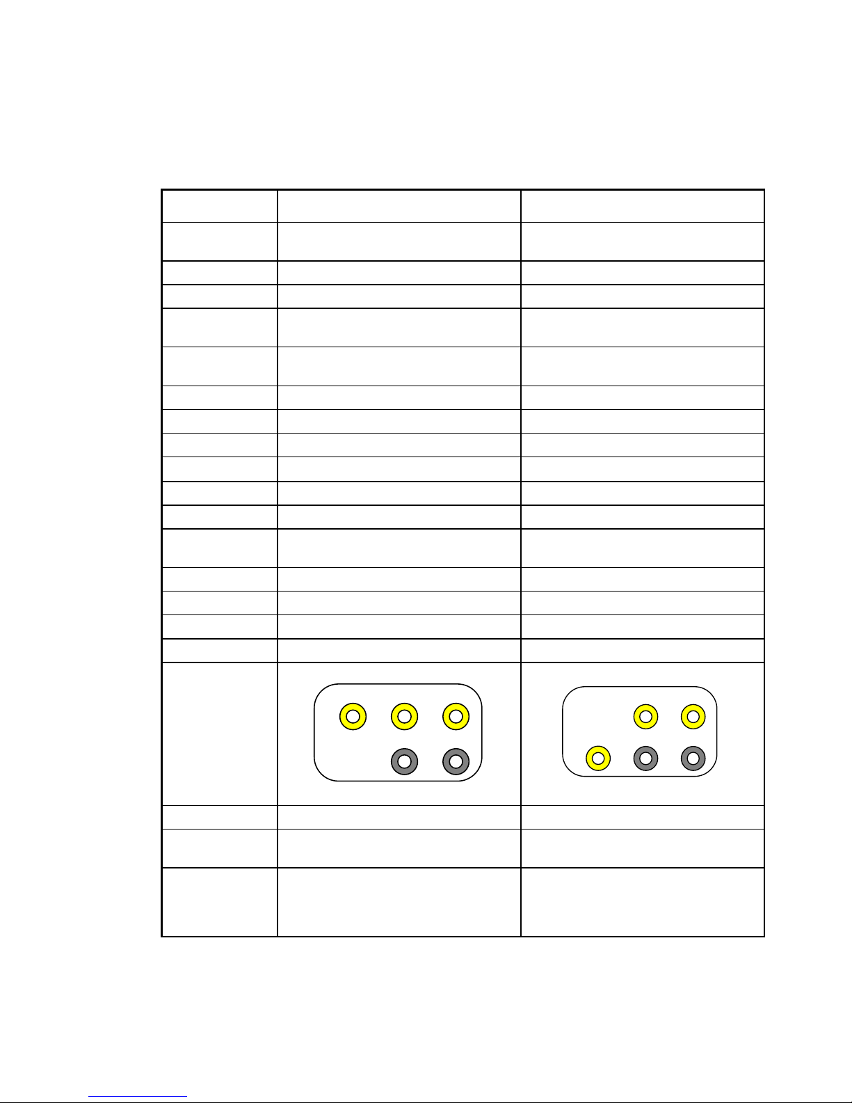
5 Remote Control
_____________________________________________________________________________________________________________________________________
5-27
Difference between 5017 and 6001 concerning hardware
Function DMM 5017 / 5017SC DMM 6001 / 6001SC, 4001/4001SC
Display 7½ digit for Vdc and Ohms
LCD
6½ digit
LED matrix
Full scale 30 100 000 for Vdc and Ohms 1 999 999
Additional frequency / period / continuity -
AC
Measurements
AC and AC+DC
frequency range 3 Hz up to 1MHz
only AC + DC
frequency range 20 Hz up to 100 kHz
Overload Limit V/Lo-plug against ground: 250V
5017SC V/Hi to Lo: 1000V
V/Lo-plug against ground: 125V
6001-01 V/Hi to Lo: 125V
NMRR >100dB (PLL inside) 60dB
Integration Times from 20ms to 100s (6½ dgt from 0.2 s) from 50 ms to 10s (6½ dgt. from 1s)
Current Ranges Five: from 200µA to 2A Two ranges: 2mA / 2 A
Resistance
up to 30MΩ 2- and 4-wire 2-wire max. 16 MΩ, 4 wire 100k
Ω
Temperature Pt10/Pt25/PT100/Pt500/Pt1000 Pt100
Memory - 100 values volatile
Trigger with trigger line (9-pole sub D connector)
or keystroke
with trigger line (3.5 mm jack plug)
Interface IEEE488, RS232 IEEE488
Filter switchable on/off or automatic -
Analog display - 100 dots
Math programs Offset, ax+b, Ratio, % Deviation Offset, %Dev, Incr, Ratio, dB, dBm
Front plugs
HI HI
Amps
V
Ω
Ω4
Sense
LO
HI
Guard
V
Ω
Α
Source
LO
Rear plugs Yes No
Switch Front/Rear manually, with open the instrument Relay
(with IEEE command or key board)
Optional
Scanner
20x4-pole, 40x2-pole, 80x1-pole
on two 50-pole sub D connector
different pin assignment
No current measurement
10x4-pole
on one 50-pole sub D connector
different pin assignment
current measurement possible
* ) DMM 5001/ 5001SC is compatible to the DMM 6001/6001 excluding Temperature and 4-wire Ohms measurement
Page 85

Compatibility
_____________________________________________________________________________________________________________________________________
5-28
Page 86

6 Calibration
_____________________________________________________________________________________________________________________________________
6-1
6 Calibration
6.1 Calibration Periods
PREMA recommends that the unit be calibrated after one year has elapsed.
Within that year, specification data are guaranteed to be valid.
6.2 PREMA Calibration Service
You can have your unit calibrated by PREMA or by a local calibration lab. Call the
telephone number indicated on the front of the manual, in order to obtain information
about the price and duration of this service. We make every effort to return the unit to
your use as quickly as possible. In addition, when we perform a full calibration, you
receive a factory certificate.
Calibrations with an official certificate can also be obtained from PREMA.
6.3 Necessary Equipment
The following aids should be available to you, in order to be able to carry out a
complete calibration of the unit:
• Multifunction Calibrator for DC Voltage, DC Current, AC Voltage, AC
Current, and Resistance to at least 100M Ω, with a minimum resolution of 6½
digits (e.g. Datron 4800), or
• Voltage Standards (e.g. Fluke 732A, 10V) and Resistance Standards and
• Short-Circuit Terminators (three of them, e.g. PREMA 3016 Short-Circuit
Terminator Set) in order to perform the zero correction .
• Connection cables with gold-plated Banana Plugs (e.g. PREMA 3014 or 3015,
Precision Cable Set)
As an alternative you can also utilize less precise sources with good short-time
stability; the value of the source can be checked with PREMA’s 8½ digit DMM 6048.
You can then enter the DMM 6048’s reading into the 5017 as calibration value.
With this method, even 5½ digit calibrators can be used to calibrate 7½ digit
multimeters.
6.4 Automated Calibration
Page 87

Automated Calibration
_____________________________________________________________________________________________________________________________________
6-2
The calibration of the 5017 can be automated with a computer and a Multifunction
Calibrator.
All measurement functions can be remotely controlled by the computer, through a
special command set (for more information see chapter “Remote Control”).
Calibration can normally be carried out entirely by remote control, without any need to
manually adjust potentiometers or capacitors.
For a complete calibration, the following measurement functions must be calibrated:
DC Voltage 300mV, 3V, 30V, 300V, 1000V
AC Voltage 200mV, 2V, 20V, 200V, 700V
DC Current 200µA, 2mA, 20mA, 200mA, 2A
AC Current 200µA, 2mA, 20mA, 200mA, 2A
2-wire Resistance 30kΩ, 300kΩ, 3MΩ, 30MΩ
4-wire Resistance 300Ω, 3k Ω, 30kΩ, 300kΩ, 3MΩ, 30MΩ
The measurement functions for frequency, period, temperature, and the lower 2-wire
resistance are automatically calibrated through the measurement functions listed above.
All ranges of individual measurement functions must be calibrated separately. In order
to properly set the zero-point, it is very important to carry out an offset correction
prior to calibration on each range of each measurement function.
Even after calibration, an Offset Correction should be carried out on a regular basis, at
least once a month.
Page 88

6 Calibration
_____________________________________________________________________________________________________________________________________
6-3
6.5 Important Steps prior to Calibration
The following items must be taken care of before the calibration procedure is started:
1. The calibration environment should be at a stable temperature of at least
18°C (64.4°F), but no more than 28°C (82.4°F). Ideally, the temperature
should be 23 ±1°C (73.4°F). In order to prevent erroneous measurements
due to temperature fluctuations, you can wrap the connectors at the unit in a
heat-insulating cloth (like a dust cloth).
2. There must be a 2-hour warm-up period before the calibration is started.
3. Make certain, that the measurement connectors are set to front operation .
If the connectors are set to rear operation, switch them to front operation, as
described in the chapter “Getting Started.”
5. An offset correction must be carried out for every measurement range of
every measurement function.
If you are working with a multifunction calibrator, the offset correction is
carried out when the unit is already connected to the calibrator, and the
calibrator is set to “Zero” (the calibrator’s zero-point).
It is important, however, that the true unit zero-point be set after calibration,
by using the short-circuit terminators on the 5017 front input connectors.
6. Wherever possible, use shielded cables, as short as possible, and with gold-
plated connectors. In this manner, you can make certain that the
thermoelectric voltage at the measurement connectors is kept as small as
possible.
7. After connecting a cable, or after changing the measurement function or
range, you should wait at least one minute, before the first measurement
value is read.
Page 89
PIN Number and Calibration Switch
_____________________________________________________________________________________________________________________________________
6-4
6.6 PIN Number and Calibration Switch
Calibration can be protected against accidental or incorrect calibrations, through the
use of a rear calibration switch and a special PIN number.
The calibration button is located on the rear panel, and can be pushed with a pointed
object (pen, pencil, paper clip, etc.). This button can be pushed after the calibration
menu has been selected. At the same time, a request to input the PIN number will
appear in the display.
Press Key Display / Action
1. Cal key on the
rear panel
1 PIN:0 000000
Enter a PIN No. (after delivery: 0000000), the display shows alternating
"CAL" and the reading with the correct PIN No..
2. MENU-IN KEY 2 CONFIGURE..
if this display does not appear press the ñ KEY until it appears
3. MENU-IN KEY 4 Calibration..
if this display does not appear press the ñ KEY until it appears
4. MENU-IN KEY 1 Enter Value..
only with the right PIN No..
5. MENU-IN KEY V +100.00000
Enter the calibration value, close with the MENU-IN KEY
6. MENU-IN KEY 1 Enter Value..
press several times to return to the calibration input menu
7. ò KEY 2 Store Cal.
with afterwards pressing of the MENU-IN KEY stores durably the
calibration data
8. Cal key on the
rear panel
to close the calibration procedure
Note: Item 7 is very important. If you forget to store the user calibration it is
completely deleted after you switch off the instrument. Then only the
factory calibration is valid.
Page 90
6 Calibration
_____________________________________________________________________________________________________________________________________
6-5
By following the steps described above, each measurement function and measurement
range is calibrated.
The following measurement functions and ranges must be calibrated:
Measurement Function Measurement Ranges
Vdc 300mV, 3V, 30V, 300V, 1000V
Vac 200mV, 2V, 20V, 200V, 1000V
Idc 200µA, 2mA, 20mA, 200mA, 2A
Iac 200µA, 2mA, 20mA, 200mA, 2A
Ω4W 300Ω, 3kΩ, 30kΩ, 300kΩ, 3MΩ, 30MΩ
Ω2W 300kΩ, 3MΩ, 30MΩ
Table: Measurement Functions to be calibrated
Vac+dc, Iac+dc, Frequency, Period and Temperature Measurement are calibrated
through the measurement functions named above.
The lower resistance ranges are only calibrated in the 4-wire resistance measurement.
Changing the PIN Number
By default, the 7-digit PIN No. is set to 0000000. If you want to change this number
please proceed as follows.
Press Key Display / Action
1. cal key on the rear
panel
1 PIN:0 000000
Enter a PIN No. (default: 0000000), with correct PIN No. the display
shows aternate "CAL" and the reading.
2. cal key on the rear
panel
to close the calibration
3. cal key on the rear
panel
1 PIN:0 000000
Now you can enter the desired 7 digit PIN No.
Table: Changing the PIN number
Page 91
Offset Correction
_____________________________________________________________________________________________________________________________________
6-6
6.7 Offset Correction
An offset correction must be carried out for the following measurement functions and
ranges:
Measurement Function Measurement Ranges
Vdc 300mV, 3V, 30V, 300V, 1000V
Vac 200mV, 2V, 20V, 200V, 700V
Idc 300µA, 3mA, 30mA, 300mA, 2A
Iac 200µA, 2mA, 20mA, 200mA, 2A
Ω2W 300Ω, 3kΩ, 30kΩ, 300kΩ, 3MΩ, 30MΩ
Ω4W 300Ω, 3kΩ, 30kΩ, 300kΩ, 3MΩ, 30MΩ
Table: Offset Correction for Measurement Functions
In order to eliminate thermoelectric voltage and lead resistance, and to correct the
zero-point, an Offset Correction must be carried out for each measurement function.
A correction of the zero-point is possible, when the existing deviation is less than
approx. 0.2% of the range’s full-scale value for DC Voltage measurements, or approx.
5% for all other functions.
If the deviation is greater, the message “Offset too high” is displayed.
Offset values that are too large can be adjusted in the “Offset” Math Program.
Note: To achieve a correct zero-point alignment, a warm-up period of at least two
hours should be observed.
After switching functions and ranges, you should wait for a running period of
at least two measurements before carrying out an offset correction.
Page 92

6 Calibration
_____________________________________________________________________________________________________________________________________
6-7
6.8 Calibrating DC Voltage
Offset Correction for DC Voltage
To carry out the Offset Correction for DC Voltage measurements, a short-circuit must
be applied to the V-Ω front input connectors (Accessory No. 3016).
After triggering a zero-point correction by pressing the zero key, an Offset
Measurement is carried out for the curren tly set measurement range.
Notice: If calibration is done with a calibrator, the calibrator's offset has to be
corrected for at the 5017 front input correction. T he cables must be
properly connected between calibrator and 5017 and the calibrator set to
Zero, prior to the Offset correction of the 5017. Now perform the 5017
offset correction by pressing the zero key on the front panel.
Important: After calibration is completed and the calibrator removed, another offset
correction must be performed , with a short-circuit, at the 5017 front input
connector as described above.
Calibration of DC Voltage
After selecting the desired measurement range, an exactly known positive or negative
reference voltage source is connected to the input connectors. The voltage can be
between 5% and 100% (preferably between 20% and 100%) of the display range for the
measurement range in question.
If the input voltage is not in this range, an error message is displayed.
The 5017 will now display a value that should correspond to the value of the known
voltage source. If the reference value deviates too much from the measured value, the
measurement range must be recalibrated.
If several measurement ranges are to be calibrated, the process described above is
started again for the next range.
Page 93

Calibration of Resistance Ranges
_____________________________________________________________________________________________________________________________________
6-8
6.9 Calibration of Resistance Ranges
Offset Correction
When zeroing two-wire resistance measurement, the V Ω-Hi and VΩ-Lo connectors
should be short-circuited, by connecting a short-circuit terminator to these front input
connectors, instead of the resistance to be measured.
In four-wire resistance measurement, the real offset value is determined, by using two
short-circuit terminators (Accessory No. 3016) to short-circuit the V Ω-Hi and VΩ-Lo
connectors first, and then the two Sense connectors. The Sense and Source connectors
are then connected to each other with a third short-circuit terminator, to accomplish a
four-wire short.
It is important to make certain, that the “shortest” short-circuit is created at the Sense
connectors, to prevent contact resistance or pass-through resistance from being
measured.
Notice: If calibration is done with a calibrator, perform a calibration offset cor
rection as discribed above with DC voltage.
Important: After calibration is completed, the 5017 zero-point must be readjusted
again, with short-circuits, as described above.
Calibration of Resistance
Resistance ranges should be calibrated through four-wire resistance measurement. The
same calibration factors are then used for two-wire resistance measurements.
Only the higher resistance ranges need to be calibrated separately in 2-wire
measurement.
In addition , all of the two-wire resistance ranges can also be calibrated sep arately.
The zero offset correction must be performed with the ZERO key. In addition, chapter
7, ‘Operating Instructions’ should be considered, esp ecially referring to compensation
for measurement cable resistance.
Page 94

6 Calibration
_____________________________________________________________________________________________________________________________________
6-9
Note: In 2-wire resistance measurement the V-Ω-Hi plug may not be
connected to the Sense-Hi plug.
6.10 Calibration of AC Voltage
An offset correction has to be proceeded for all ranges as described for the DC voltage.
Calibration of AC Voltage measurement is carried out without DC Voltage coupling.
The AC Voltage ranges should be calibrated with a Sine Voltage that has a frequency of
1kHz.
The same calibration factor is transferred for the AC Voltage function with DC
Component.
In all other ways, you can proceed as with DC Voltage calibration.
6.11 Calibration of DC and AC Current
An offset correction should be carried out with open connectors. During AC Current
calibration, only the function for AC Current without DC Component is calibrated.
The reference currents shall consist of DC current for the DC Current function, and of
a 1kHz Sine Current for the AC Current function.
Notice: In the 2A range, the calibration current must not exceed 1A.
6.12 Calibration of Temperature
1. Preparations
a) Warmup-period: The DMM 5017 to be calibrated should have run for at least 1h.
2. TEMP-Function: ZERO Offset Correction
a) Insert a four-wire shorting-bridge at the input of the DMM5017, i.e. shorten the four
DMM 5017 Volt/Ohm-inputs - Sense and Source - HI against LO and both pairs
against each other.
b) On the DMM5017 select 1sec integration time and press the TEMP-button. The
DMM5017 will then display ‘Sensor ?’, because ZERO Ohms as sensor input is not
Page 95

Calibration of Temperature
_____________________________________________________________________________________________________________________________________
6-10
specified. But performing this sequence of operations corrects for the OHMfunction ZERO-offset, with the OHM-function implemented as fundamental function
for the Temperature-measurement with RTDs. That means here, the DMM5017
display ‘Sensor ?’ is not an error !
c) Press the following buttons in sequence to select the RTD-type (e.g. Pt 100):
Menu/↵ A 3 Device ↵ A 3 Temp Sensor ↵ A Pt 100 ↵ Menu/OUT.
Wait for some 10min for thermal stabilization.
d) On the DMM5017 with the TEMP-function selected perform the ZERO-offset
correction by pressing the following buttons in sequence:
2nd TIME/ZERO
The DMM5017-display will now show: ‘done’.
3. TEMP-Function: Calibration
a) Remove the four-wire shorting-bridge from the DMM5017 input terminals and
connect the RTD of the above selected RTD-type onto which the following
calibration has to be performed.
b) On the DMM5017 press again the TEMP-button: The actual temperature is now
displayed with the EN60751 factory calibration. Wait for another some 10min for
thermal stabilization.
On the DMM5017 activate the calibration mode by pressing the Cal-button on the
rear. The display will now ask for the input of the PIN number (Personal
Identification No.) that saves your data under this secret No.. Enter your PIN here or
simply press the Menu/↵-button without entering any PIN: The DMM5017-display
now starts flashing alternatingly ‘CAL.’ and the actual temperature display with the
EN60751 factory calibration.
c) Press the following buttons in sequence to recalibrate the DMM5017 TEMP-
function:
Menu/↵ A 2 CONFIGURE ↵ A 4 Calibration ↵ A 1 Enter Value ↵ <> now
input the new temperature calibration value here ↵
To ensure the successful recalibration the further flashing DMM5017-display now
shows ‘Cal.’ and the recently entered temperature calibration value.
d) Press the following buttons to permanently save the new temperature calibration
value:
Menu/↵ A 2 CONFIGURE ↵ A 4 Calibration ↵ A 2 Store Cal. ↵
The DMM5017 displays ‘wait...’ until the data recording into the EEPROM has
finished.
Then the DMM5017 starts flashing again still indicating that the calibration mode
has been activated.
e) Press the Cal-button on the rear of the DMM5017 to leave the calibration mode.The
DMM5017 now displays the recalibrated temperature calibration value.
Page 96

6 Calibration
_____________________________________________________________________________________________________________________________________
6-11
4. TEMP-Function: Extended list of RTDs
Press the following buttons in sequence to select the recently calibrated RTD, e.g.
Pt100 :
Menu/↵ A 3 DEVICE ↵ A 3 Temp. Sensor ↵ A 6 Cal. Pt100 ↵ Menu/OUT.
Cal. Pt100 is new in this list as the USER calibrated version of a Pt100-Sensor. The
DIN-EN 60751 calibrated version is still available in the menu as
A 3 Pt100 but without the addendum Cal.
6.13 Storing Calibration Values
Storage of calibration values is absolutely necessary to store them durably. Every
calibration step is stored only temporarily, so that the files are deleted if you switch of
the instrument.
If you wish to interrupt a calibration procedure and turn off the unit, you can do so, only
if you store the calibration with the menu "Store Cal." before you switch off power.
Y ou could then continue the procedure the next day for example, from the point where
you left off.
Page 97

7 Operating Instructions
_____________________________________________________________________________________________________________________________________
7-1
7 Operating Instructions
7.1 DC Voltage Measurement
Input Resistance in DC Voltage
To make use of the high linearity of the measurement process, the input resistance for
voltage measurements up to 3V is set very high (>10GΩ). In this range, the unit allows precise measurements, with a maximum load error of 1ppm, even at measurement objects with an internal resistance of 1kΩ.
In the 30V, 300V, and 1,000V ranges, for example, and with a 100Ω internal resistance in a measurement object with a resolution of 100,000, a corresponding error of
one digit step occurs.
The values of the input resistance in the individual measurement ranges, and the
maximum display ranges, are shown in the following table:
Full Input Maximum
Range Scale Resistance Resolution
_____________________________________________________
300 mV 30 100 000 10 GΩ 10 nV
3 V 30 100 000 10 GΩ 100 nV
30 V 30 100 000 10 MΩ 1 µV
300 V 30 100 000 10 MΩ 10 µV
1000 V 10 100 000 10 MΩ 1 mV
Page 98
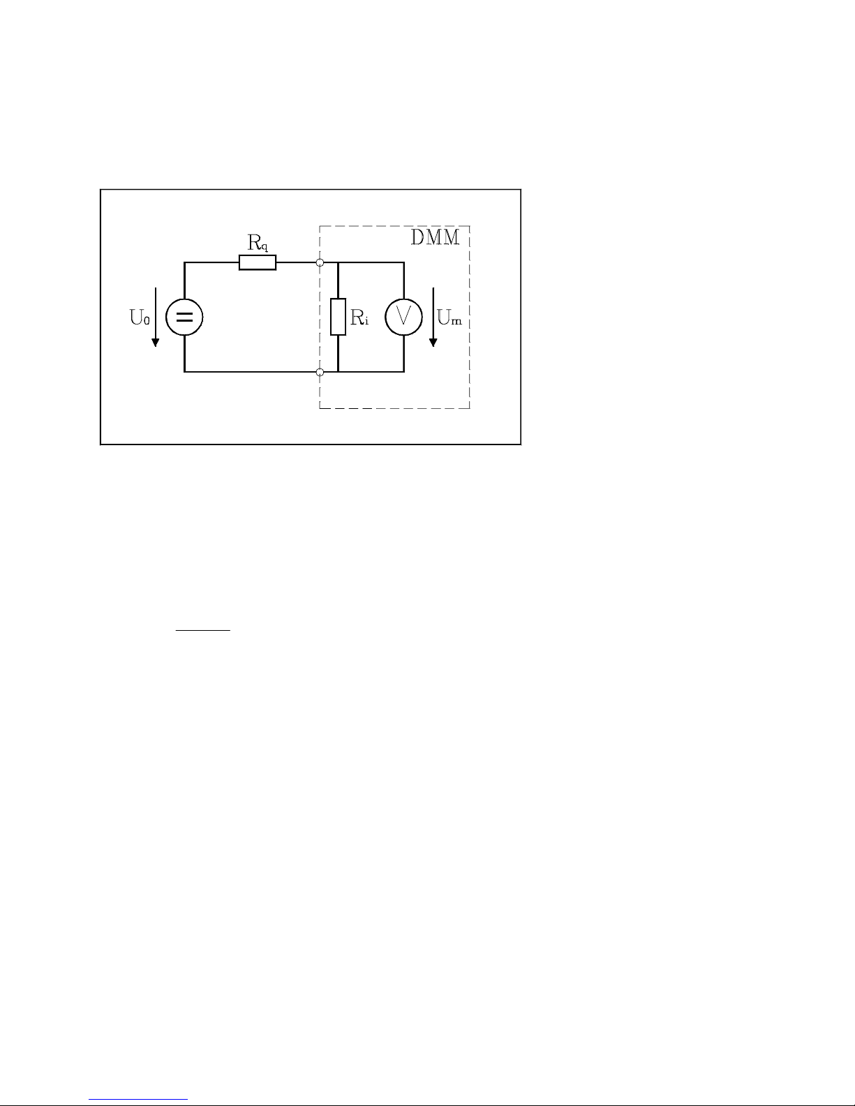
DC Voltage Measurement
_____________________________________________________________________________________________________________________________________
7-2
The influence of the source resistance is visualized in the following diagram:
Figure: Influence of source resistance on the measurement unit
R
i
= Input Resistance of the Multimeter ( 10MΩ or >1GΩ )
R
q
= Source Resistance of the Measurement Object
U
o
= Voltage of the Measurement Object
The error, in %, of a measurement, is calculated as follows:
Example: R
i
>= 1GΩ; R q = 10kΩ
Error = 0.0001% (1 ppm)
The error rating, in ppm (parts per million), often used in measurement technology, is
derived from: Error(%) x 10,000.
Series Mode Suppression
One of the main advantages of the integrating measurement process lies in the high
suppression of series AC voltage components (e.g. main line scatter), which are
overlaid on the actual signal voltage. For frequencies, where the measurement time is
an integer multiple of the period length, an infinitely high noise suppression level
theoretically results.
Short-term fluctuations of the mains frequency would lead to measurement errors in
case of fixed measurement times.
Error(%)
R
RR
=
×
+
100
q
qi
Page 99
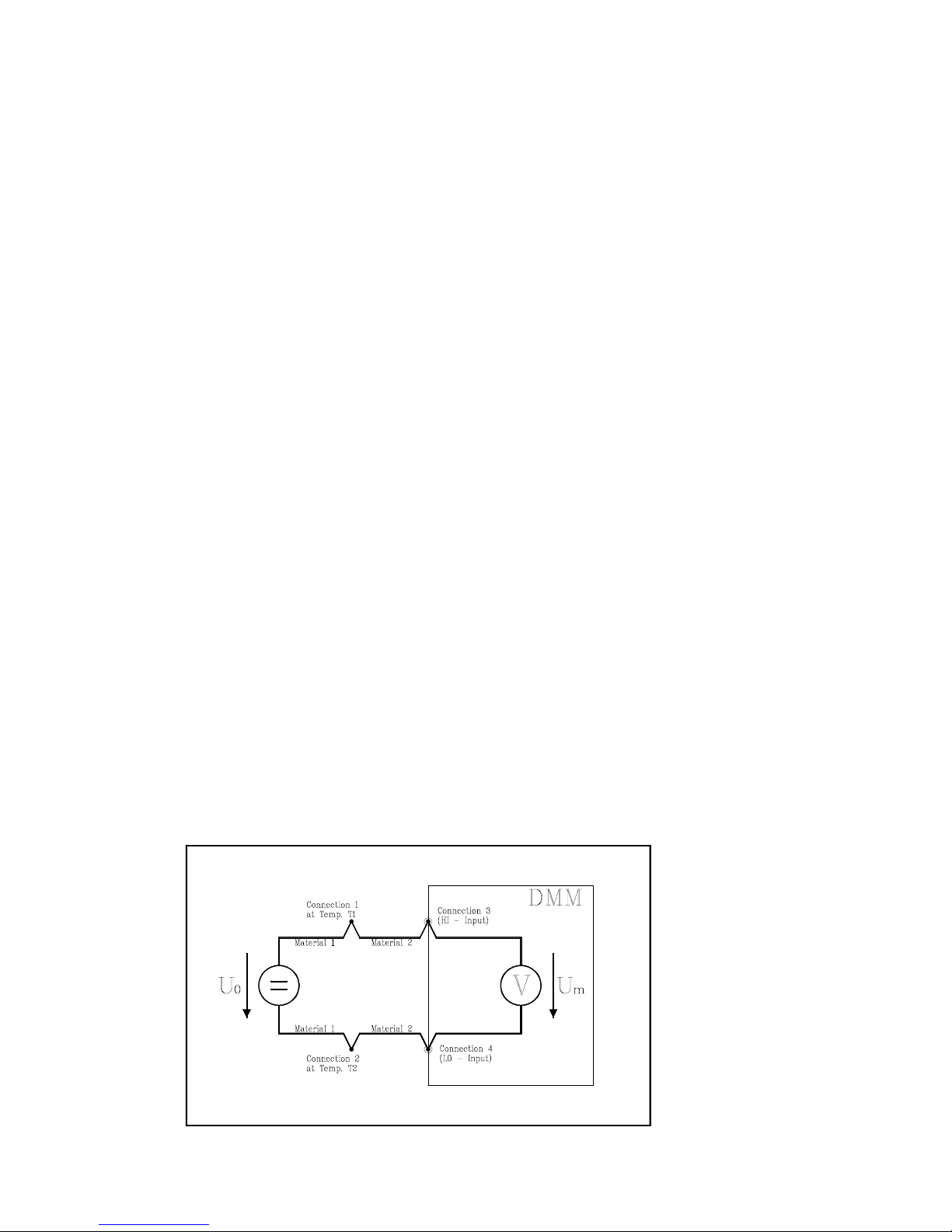
7 Operating Instructions
_____________________________________________________________________________________________________________________________________
7-3
That is why, in the 5017 a PLL circuit (Phase Locked Loop) is used to synchronize
the measurement time with the period of the main line frequency. An integer multiple
of the mains period is always contained in the measurement time.
Due to the fully integrating measurement process, the positive and negative halfwaves of line voltage are neutralized. Line scatter can thereby be completely suppressed.
The 5017 achieves a Series Mode Suppression of >100 dB with line frequencies of
50 / 60Hz ± 5%.
Common Mode Suppression
The ability of a measurement device, to display only the desired differential signal
between the “HI” and “LO” inputs, while suppressing an equal voltage on both
clamps against ground, is designated as Common Mode Suppression. In an ideal
system, no errors would be generated, but in real life, scatter capacitances, isolation
resistances, and non-symmetrical resistances convert a part of the common mode
voltage into a series voltage.
Common mode suppression in the 5017 is more than 160dB, with a non-symmetry of
1kOhm in the leads.
Thermal Voltages
One of the most common error sources in DC Voltage measurement in the low signal
range is the thermal voltage produced by thermal EMF.
These thermal voltages occur at the contact points of different metals that are at the
same or different temperature levels.
Diagram: Thermal Voltage sources in a measurement circuit
Page 100

DC Voltage Measurement
_____________________________________________________________________________________________________________________________________
7-4
The sketch shows the possible thermal voltage sources in a measurement circuit,
which can exist at an external connection point (Contact 1/2), but can also occur in
the connectors of the measurement unit.
It is always important to carry out all connections with the same material, or at least to
use materials, that produce very small thermal voltages, when they are put in contact
with each other.
The table below shows the different thermal voltages for diverse material
combinations:
Contact Materials approx. Thermal Voltage
Cu - Cu < 0,3µ/°C
Cu - Ag (Silver) 0,4µ/°C
Cu - Au (Gold) 0,4µ/°C
Cu - Sn (Tin) 2-4µ/°C (dep. on composition)
For example, if material 1 consists of a silver lead and material 2 consists of a copper
cable, a connection between contacts 1 and 2 at a temperature difference of just 1°C
already results in a thermoelectric voltage of 400nV. In the smallest voltage range,
with a resolution of 7½ digits (10nV sensitivity), this would result in an error of ± 40
digits.
Noise Effects Through Inductive Interferences
If the measurement leads are located near changing magnetic fields, generated for
example by a nearby high-voltage line, induction will cause an interfering voltage in
series with the measurement voltage.
By using twisted pair measurement leads, inductive interferences by a magnetic field
can be very strongly reduced. One should also take care not to allow the leads to hang
around loosely and move around during measurements, since that can cause error
voltages.
An additional measure for the reduction of noise is to increase the distance to the
magnetic field, or if possible to shield measurements from it.
 Loading...