

Page 1
Displays
lection of inputs and outputs for display of temperature,
volume and weight, etc. Feature linearisation, scaling,
and difference measurement functions for programming
via PReset software.
Programmable displays with a wide se-
Ex barriers
signals as well as HART
converters / frequency signals and control systems in Ex
zone 0, 1 & 2 and for some modules in zone 20, 21 & 22.
Isolation
signals as well as HART
with both loop-powered and universal isolators featuring
linearisation, inversion, and scaling of output signals.
Temperature
form B mounting and DIN rail modules with analogue
and digital bus communication ranging from applicationspecifi c to universal transmitters.
Universal
universal options for input, output and supply. This range
offers a number of advanced features such as process
calibration, linearisation and auto-diagnosis.
Interfaces for analogue and digital
Galvanic isolators for analogue and digital
A wide selection of transmitters for DIN
PC or front programmable modules with
®
signals between sensors / I/P
®
signals. A wide product range
5909
Loop Link
USB Communications
Interface
No. 5909V101-IN (0722)
From ser. no. 040654001
DK
UK
FR
DE
Side 1
Page 15
Page 29
Seite 43
SIGNALS THE BEST
Page 2

USB-KOMMUNIKATIONSINTERFACE
LOOP LINK 5909
Indholdsfortegnelse
Advarsler ............................................................................ 2
Sikkerhedsregler ................................................................. 3
EF-overensstemmelseserklæring ....................................... 5
Anvendelse ......................................................................... 6
Teknisk karakteristik ........................................................... 6
Installation .......................................................................... 6
Systemkrav ......................................................................... 6
Installation af PReset ......................................................... 6
Installation af USB-drivere til Windows
Specielt for Windows
Specielt for Windows
®
98SE og ME .............................. 7
®
XP .............................................. 8
Installation af USB-drivere til Windows
Konfigurering af USB-kommunikation i PReset ................. 13
Forbindelse af PR-moduler ved EZ-Mini-Hook tilslutning . 14
Forbindelse af PR-moduler ved modular stiktilslutning ..... 14
®
98SE, ME og XP . 6
®
Vista .................... 9
1
Page 3
GENERELT
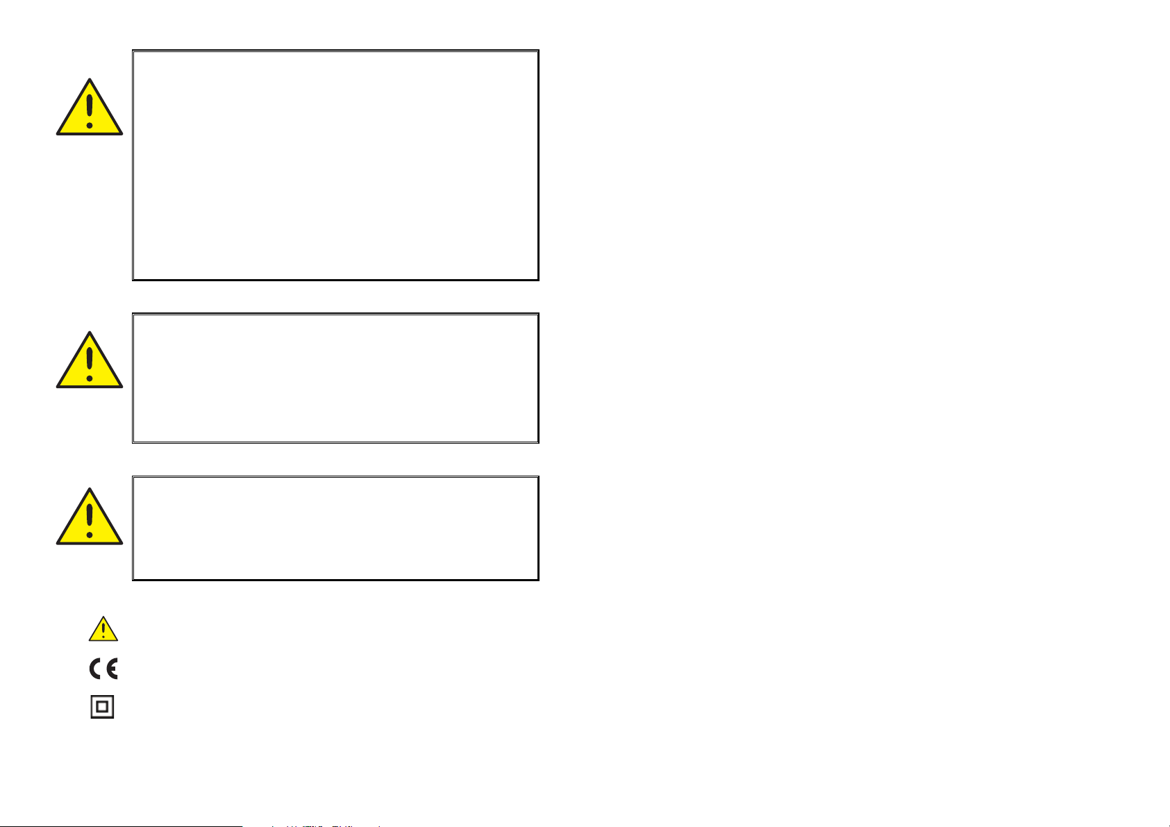
FARLIG
SPÆNDING
ADVARSEL
Dette modul kan ved tilslutning til SYSTEM 5000 gennem kommunikationskablet få forbindelse til livsfarlige elektriske spændinger. Hvis denne advarsel ignoreres, kan det føre til alvorlig
legemsbeskadigelse eller mekanisk ødelæggelse.
For at undgå faren for elektriske stød og brand, skal manualens
sikkerhedsregler overholdes, og vejledningerne skal følges.
Modulet må kun benyttes som beskrevet i det følgende.
Manualen skal studeres omhyggeligt, før modulet tages i brug.
Kun kvalificeret personale (teknikere) må benytte dette modul.
Hvis modulet ikke anvendes som beskrevet i denne manual, forringes modulets beskyttelsesforanstaltninger.
ADVARSEL
Følgende operationer må kun udføres på modulet, når kommunikationskablerne er uden forbindelse til SYSTEM 5000 og PC:
Fejlfinding på modulet.
Reparation af modulet må kun foretages af PR electronics A/S.
SIKKERHEDSREGLER
DEFINITIONER:
Farlige spændinger er defineret som områderne:
75...1500 Volt DC og 50...1000 Volt AC.
Teknikere er kvalificerede personer, som er uddannet eller oplært til at kunne
udføre installation, betjening eller evt. fejlfinding både teknisk og sikkerhedsmæssigt forsvarligt.
Operatører er personer, som under normal drift skal indstille og betjene
produktets trykknapper eller potentiometre, og som er gjort bekendt med indholdet af denne manual.
MODTAGELSE OG UDPAKNING:
Udpak modulet uden at beskadige dette, og sørg for, at manualen altid følger
modulet og er tilgængelig.
Kontrollér ved modtagelsen, at modultypen svarer til den bestilte.
MILJØFORHOLD:
Undgå direkte sollys, kraftigt støv eller varme, mekaniske rystelser og stød, og
udsæt ikke modulet for regn eller kraftig fugt. Om nødvendigt skal opvarmning,
udover de opgivne grænser for omgivelsestemperatur, forhindres ved hjælp af
ventilation.
Alle moduler hører til Installationskategori II, Forureningsgrad 1 og Isolationsklasse II.
INSTAL-
LATION
ADVARSEL
Kommunikationshunstikket i SYSTEM 5000 har forbindelse til
indgangsklemmer, hvor der kan forekomme farlige spændinger.
Det må kun tilsluttes programmeringsenheden 5909 via det
fastmonterede kommunikationskabel.
SIGNATURFORKLARING:
Trekant med udråbstegn: Advarsel / krav. Hændelser der kan
føre til livstruende situationer.
CE-mærket er det synlige tegn på modulets overensstemmelse
med EU direktivernes krav.
Dobbelt isolation er symbolet for, at modulet overholder ekstra
krav til isolation.
INSTALLATION:
Modulet må kun tilsluttes af teknikere, som er bekendte med de tekniske udtryk, advarsler og instruktioner i manualen, og som vil følge disse.
Hvis der er tvivl om modulets rette håndtering, skal der rettes henvendelse til
den lokale forhandler eller alternativt direkte til:
PR electronics A/S, Lerbakken 10, DK-8410 Rønde tlf: +45 86 37 26 77.
32
Page 4

PROGRAMMERING:
Under programmering skal måling og tilslutning af eksterne spændinger udføres
i henhold til denne manual, og manualen for den enhed som skal programmeres, og teknikeren skal benytte sikkerhedmæssigt korrekte værktøjer og
instrumenter.
BETJENING UNDER NORMAL DRIFT:
Operatører må kun indstille eller betjene modulerne, når disse er fast installeret
på forsvarlig måde i tavler el. lignende, så betjeningen ikke medfører fare for liv
eller materiel. Dvs., at der ikke er berøringsfare, og at modulet er placeret, så
det er let at betjene.
EF-OVERENSSTEMMELSESERKLÆRING
Som producent erklærer
PR electronics A/S
Lerbakken 10
DK-8410 Rønde
hermed at følgende produkt:
Type: 5909
Navn: Loop Link
RENGØRING:
Modulet må, i spændingsløs tilstand, rengøres med en klud let fugtet med destilleret vand.
ANSVAR:
I det omfang instruktionerne i denne manual ikke nøje er overholdt, vil kunden
ikke kunne rette noget krav, som ellers måtte eksistere i henhold til den indgåede salgsaftale, mod PR electronics A/S.
er i overensstemmelse med følgende direktiver og standarder:
EMC-direktivet 2004/108/EF og senere tilføjelser
EN 61326
For specifikation af det acceptable EMC-niveau henvises til modulets
elektriske specifikationer.
Lavspændingsdirektivet 2006/95/EF og senere tilføjelser
EN 61010-1
Rønde, 31. maj 2007 Peter Rasmussen
Producentens underskrift
4
5
Page 5
Anvendelse:
Loop Link 5909 er et USB-kommunikationsinterface til opsætning og monitorering af PR electronics’ pc-programmerbare moduler. USB-kommunikationen
understøttes af Windows
moduler, som findes i konfigurationsprogrammet PReset ver 5.0 eller højere,
kan benytte Loop Link 5909.
®
-versionerne 98SE, ME, 2000, XP og Vista. De PR-
Teknisk karakteristik:
Pc program-cd’en PReset ver 5.0 eller højere indeholder nødvendige (usignerede) USB-drivere. Loop Link 5909 forsynes fra pc’ens USB-port. Hvis man
ønsker at spare strøm på en bærbar pc, kan man tilslutte en eksternt forsynet
hub og montere 5909’s USB-stik i denne. Der er galvanisk isolation mellem
kommunikationsstikket til PR-moduler og USB-tilsluningen på pc’en.
Installation:
Systemkrav:
Windows® 98SE, ME, 2000, XP og Vista med følgende anbefalinger:
Hukommelse: 16 MB
Skærmopløsning: 800 x 600
Harddiskplads: 12 MB
Installation af PReset:
USB-kommunikationsinterfacet Loop Link 5909 må ikke være tilsluttet pc’ens
USB-port, før PReset-programmet er installeret.
PReset installeres på din harddisk, og registreringsdatabasen opdateres med
alle nødvendige oplysninger om programmet. Der vil automatisk blive oprettet et
PReset-ikon på skrivebordet.
1. Sæt cd-rom’en i dit cd-rom-drev, dialogen ”InstallShield Wizard
PReset - INSTALLER” vises automatisk.
2. Når installationsprogrammet er startet, vises en vejledning på skærmen, som hjælper dig gennem resten af installationen.
3. Hvis AutoRun er slået fra i Windows
startes installa tionsprogrammet ”cd-drev:\PResetWin\setup.exe”
med [Kør] i menuen start.
®
98SE, ME, 2000, XP og Vista,
2. Efter kort tid vises guiden ”Ny hardware fundet”. Denne guide hjælper dig gennem den første USB-driver installation.
3. Ved tryk på [Udfør] bliver den første USB-driver installeret.
4. Guiden starter igen og hjælper dig gennem den anden USB-driver
installation.
5. Ved tryk på [Udfør] er USB-driver installationen fuldført.
Specielt for Windows® 98SE og ME:
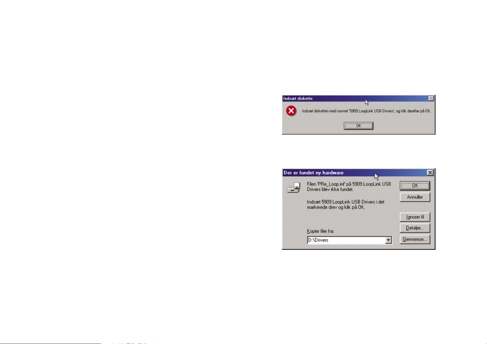
1. Når Windows® 98SE og ME søger efter driverne, kan følgende meddelelse forventes:
2. Efter klik på OK fremkommer en dialog, hvor stien
”cd-rom-drev:\drivere” skal angives. Du kan bruge [Gennemse] eller
selv indtaste stien.
3. Resten af installationen følger vejledningen ”Installation of USB-drivere til Windows
®
98SE, ME og XP”.
Installation af USB-drivere til Windows
Installer USB-driverne, medens PReset cd’en sidder i pc’en, altså umiddelbart
efter PReset-installationen. Vær opmærksom på, at der skal installeres to USBdrivere.
1. Tilslut Loop Link 5909 til pc’ens USB-port.
®
98SE, ME og XP
6
7
Page 6
Specielt for Windows® XP:
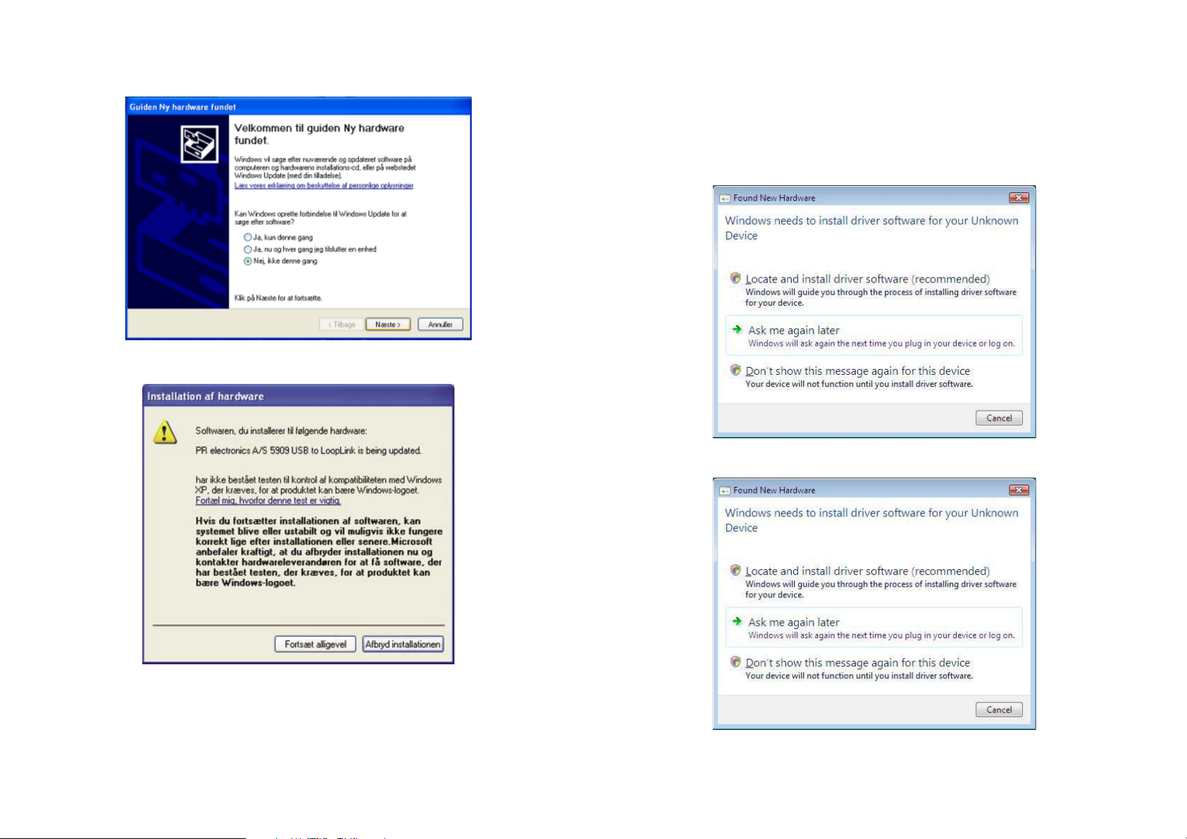
1. Du skal vælge [Nej, ikke denne gang] til følgende dialog:
2. Du skal vælge [Fortsæt alligevel] til følgende dialog:
Installation af USB-drivere til Windows
Installer USB-driverne, medens PReset cd’en sidder i pc’en, altså umiddelbart
efter PReset-installationen.
1. Tilslut Loop Link 5909 til pc’ens USB-port.
2. Efter kort tid vises guiden ”Ny hardware fundet”. Denne guide hjælper dig gennem den første USB-driver installation.
3. Klik [Annuller] på følgende skærmbillede:
4. Klik [Annuller] på efterfølgende skærmbillede:
®
Vista
3. Resten af installationen følger vejledningen ”Windows
og XP”.
8
®
98SE, ME
9
Page 7
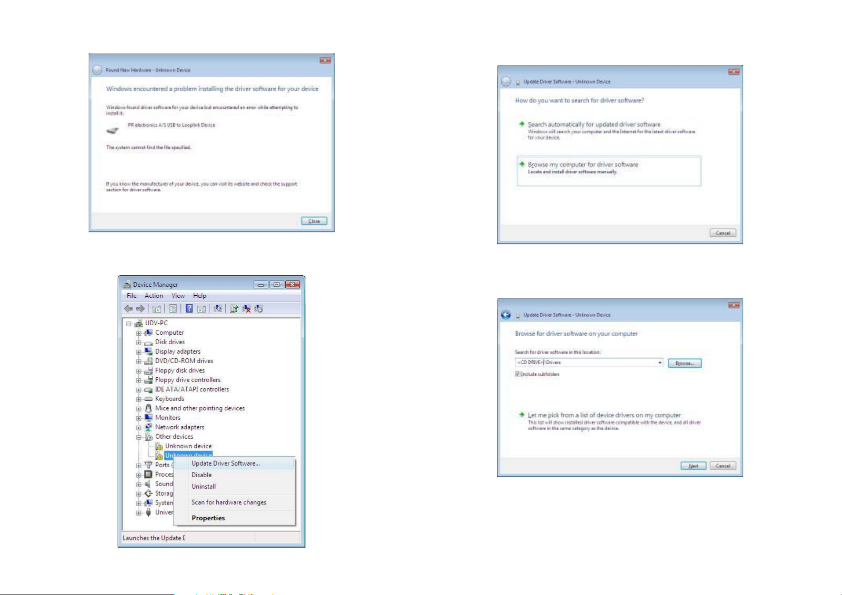
5. Klik [Luk] på efterfølgende skærmbillede:
6. Åben enhedshåndtering og højreklik på [Ukendt enhed]. Venstreklik
derefter på [Opdater driversoftware].
7. Klik [Søg på computeren efter driversoftware] på efterfølgende
skærmbillede:
8. På efterfølgende skærmbillede skal stien ”cd-rom-drev:\drivere”
angives. Du kan bruge [Gennemse] eller selv indtaste stien. Klik
derefter på [Næste].
10 11
Page 8
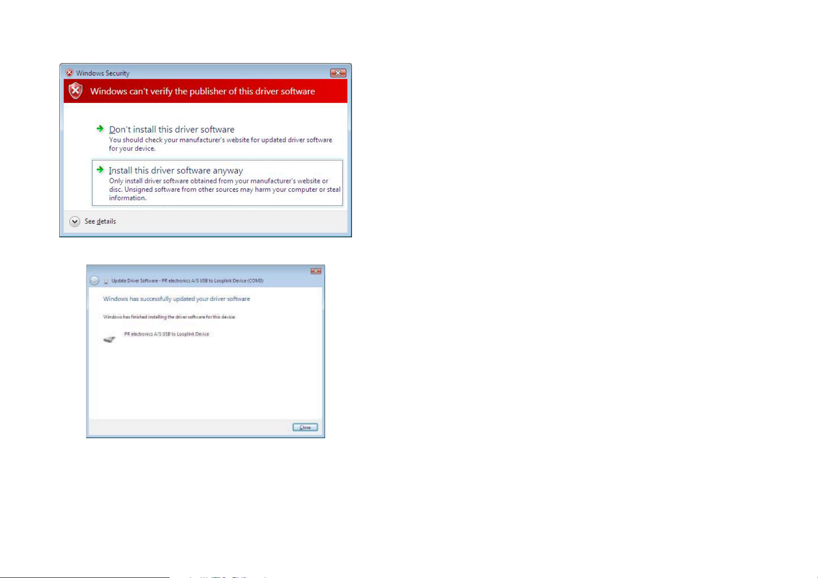
9. Klik [Installer driversoftware alligevel] på efterfølgende skærmbillede:
10. Klik [Luk] på efterfølgende skærmbillede:
Konfigurering af USB-kommunikation i PReset:
1. Start PReset-programmet og vælg [Funktioner] [Vælg COM-port], og
”Option” vinduet vises på skærmen.
2. Vælg ”Next 5909”. PReset vælger nu en COM-port, som sammenkædes med den USB-port, Loop Link er forbundet til.
3. Hvis du vil have Loop Link konfigureret til andre USB-porte, skal du
forbinde Loop Link til disse porte og installere USB-driverne for hver
port. De andre USB-porte bliver først sammenkædet med en COMport i PReset, når ”Next 5909” er valgt.
12 13
Page 9
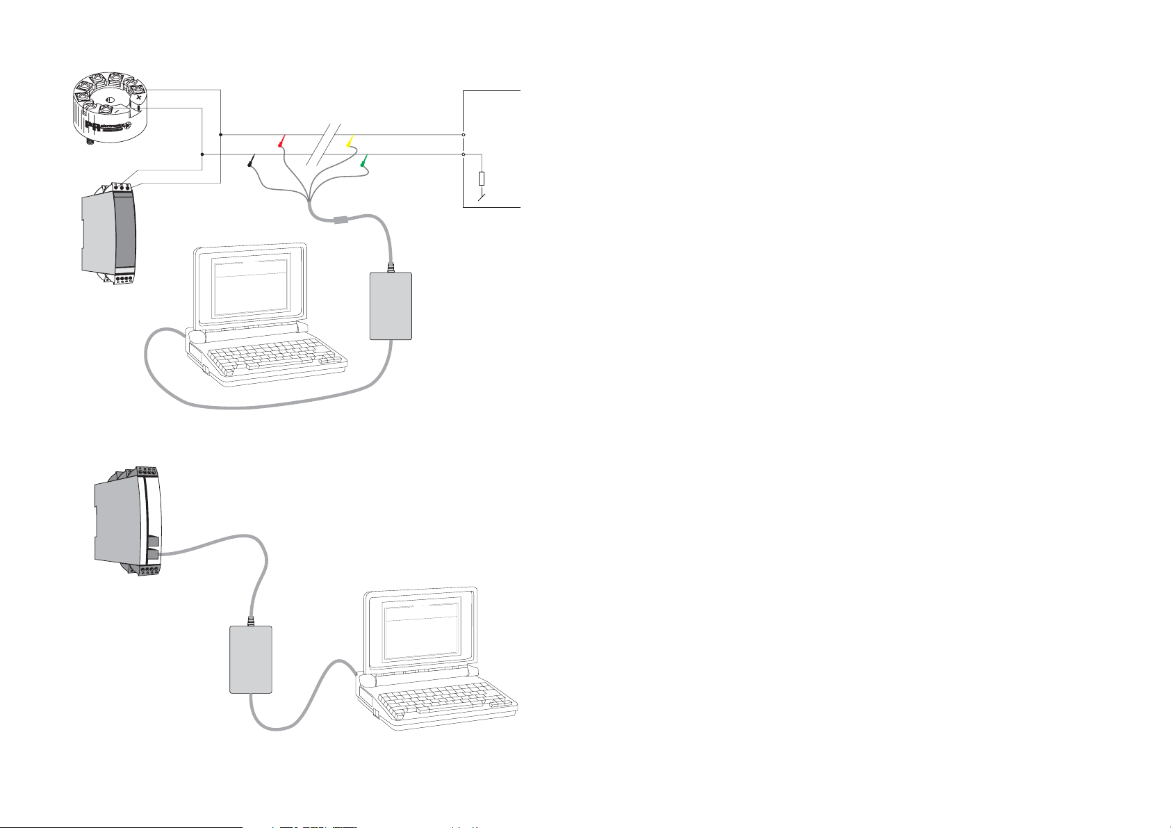
Forbindelse af PR-moduler ved EZ-Mini-Hook tilslutning
USB COMMUNICATIONS INTERFACE
1
2
PR 5331, 5333, 5334, 5335
11
13
PR 6331, 6333, 6334, 6335
(21)
(23)
Sort
n
o
i
t
p
O
e
g
a
u
g
n
a
L
n
o
t
i
a
c
i
n
u
m
m
o
C
t
u
p
t
u
O
t
u
p
n
I
t
c
u
d
o
r
P
e
l
1
i
3
F
3
5
p
o
t
e
R
P
0
1
-
-
8
4
0
0
2
:
e
t
a
D
4
9
5
1
0
2
3
4
0
:
o
l
n
a
i
r
e
S
s
i
c
n
o
r
t
c
l
e
e
R
P
:
o
n
g
a
T
u
p
n
i
g
o
l
a
n
A
:
e
p
y
t
t
u
p
n
I
e
g
n
a
r
t
u
p
n
I
n
i
o
t
c
e
n
n
o
C
i
o
t
c
n
u
j
d
l
o
C
t
e
s
n
o
p
s
e
R
t
u
p
t
u
o
g
o
l
a
n
A
t
:
:
m
o
c
n
:
e
i
m
m
0
2
-
4
:
e
p
y
t
t
u
p
t
u
O
C
E
/
I
I
N
D
0
0
1
t
P
a
c
s
p
U
:
r
o
r
r
e
r
o
s
n
e
S
C
0
0
.
0
5
-
0
0
.
0
e
r
i
w
3
-
-
-
-
-
-
:
p
c
e
s
0
0
.
1
Afbryd
Stikfor-
bindelse
Gul
*
Grøn
*
* Kun forbundet ved
on-line programmering
Rød
0
0
:
0
3
:
8
0
A
l
e
Loop
Link
USB-kabel
Forbindelse af PR-moduler ved modular stiktilslutning
Programmeringskabel
med modularstik
Modtagende
udstyr
+Vforsyning
Indgang
LOOP LINK 5909
Contents
Warnings ............................................................................ 16
Safety instructions .............................................................. 17
EC Declaration of Conformity ............................................ 19
Application ......................................................................... 20
Technical characteristics .................................................... 20
Installation .......................................................................... 20
System requirements ......................................................... 20
Installation of PReset ......................................................... 20
Installation of USB drivers for Windows
Special instructions for Windows
Special instructions for Windows
Installation of USB drivers for Windows
Configuration of USB communication in PReset ............... 27
Connection of PR modules using EZ-Mini-Hooks ............. 28
Connection of PR modules using a modular connector .... 28
®
98SE, ME and XP 20
®
98 SE and ME ........ 21
®
XP ........................... 22
®
Vista ................. 23
PR 5114, 5115, 5116, 5131
0
0
:
0
3
:
8
0
n
o
i
t
p
O
e
g
a
u
g
n
a
L
n
o
i
t
a
c
i
n
u
m
m
o
C
t
u
p
t
u
O
t
u
p
n
I
t
c
u
d
o
r
P
1
e
l
i
3
F
3
5
p
o
t
e
R
P
0
1
-
-
8
4
0
0
2
:
e
t
a
D
4
9
5
1
0
2
3
4
0
:
o
n
l
a
r
i
e
S
s
c
i
n
o
r
t
c
l
e
e
R
P
:
o
n
g
a
T
i
n
g
l
o
a
n
A
e
p
y
t
t
u
p
n
I
g
n
a
r
t
u
p
n
I
o
i
t
c
e
n
n
o
C
t
c
n
j
u
l
d
o
C
e
s
n
o
p
s
e
R
t
u
p
t
u
o
g
l
o
a
n
A
t
u
p
:
:
e
:
n
:
p
m
o
c
n
o
i
:
e
m
i
t
A
m
0
2
-
4
:
e
p
y
t
t
u
p
t
u
O
C
E
/
I
I
N
D
0
0
1
t
P
l
e
a
c
s
p
U
:
r
o
r
r
e
r
o
s
n
e
S
C
0
.
0
0
5
-
0
0
.
0
e
i
r
w
3
-
-
-
-
-
c
e
s
0
0
.
1
Loop
Link
USB-kabel
14 15
15
Page 10
GENERAL
WARNING
When connected to SYSTEM 5000 by the communication cable,
this module can get connected to hazardous electric voltages.
Ignoring this warning can result in severe personal injury or mechanical damage.
To avoid the risk of electric shock and fire, the safety
instructions of this manual must be observed and the guidelines
followed.
The module must only be applied as described in the following.
Prior to the commissioning of the module, this manual must be
examined carefully.
Only qualified personnel (technicians) should use this module.
If the module is used in a manner not specified by the manufacturer, the protection provided by the module may be impaired.
SAFETY INSTRUCTIONS
DEFINITIONS:
Hazardous voltages have been defined as the ranges: 75...1500 Volt DC, and
50...1000 Volt AC.
Technicians are qualified persons educated or trained to mount, operate, and
also trouble-shoot technically correct and in accordance with safety regulations.
Operators, being familiar with the contents of this manual, adjust and operate
the knobs or potentiometers during normal operation.
RECEIPT AND UNPACKING:
Unpack the module without damaging it and make sure that the manual always
follows the module and is always available. The packing should always follow
the module until this has been permanently mounted.
Check at the receipt of the module whether the type corresponds to the one
ordered.
HAZARD-
OUS
VOLTAGE
INSTAL-
LATION
WARNING
The following operations must only be carried out on a module
that is not connected to SYSTEM 5000 and a PC:
Troubleshooting the module.
Repair of the module must be done by PR electronics A/S only.
WARNING
The female communication connector of SYSTEM 5000 is connected to the input terminals on which dangerous voltages can
occur. It must only be connected to the programming unit 5909
by way of the attached communication cable.
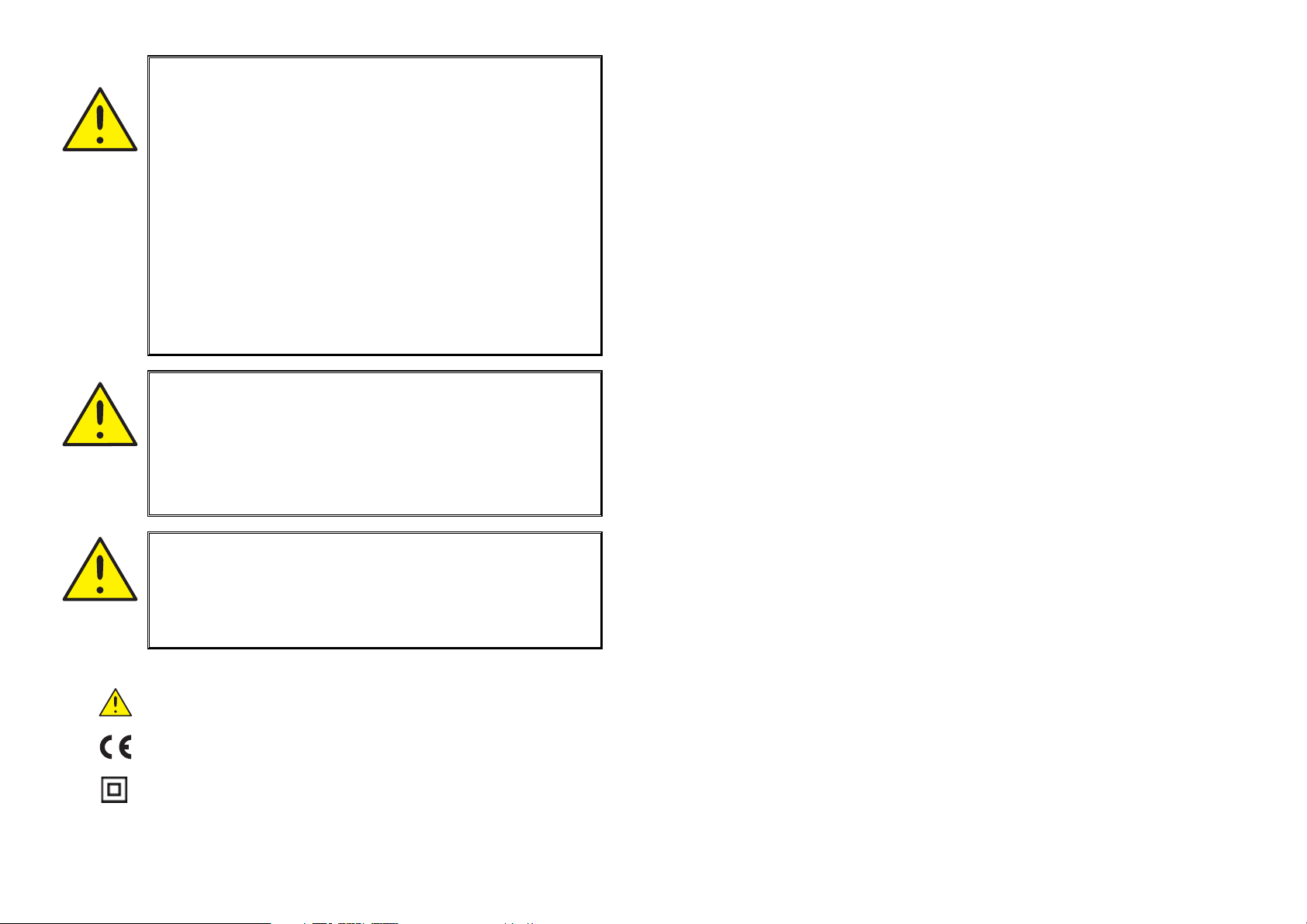
SYMBOL IDENTIFICATION:
Triangle with an exclamation mark: Warning/demand.
Potentially lethal situations.
The CE mark proves the compliance of the module with the re-
quirements of the EU directives.
The double insulation symbol shows that the module is
protected by double or reinforced insulation.
ENVIRONMENT:
Avoid direct sunlight, dust, high temperatures, mechanical vibrations and shock,
as well as rain and heavy moisture. If necessary, heating in excess of the stated
limits for ambient temperatures should be avoided by way of ventilation.
All modules fall under Installation Category II, Pollution Degree 1, and Insulation
Class II.
MOUNTING:
Only technicians who are familiar with the technical terms, warnings, and
instructions in the manual and who are able to follow these should connect the
module.
Should there be any doubt as to the correct handling of the module, please
contact your local distributor or, alternatively,
PR electronics A/S, Lerbakken 10, DK-8410 Rønde tlf: +45 86 37 26 77
16 17
1716
Page 11

PROGRAMMING:
During programming, the measuring and connection of external voltages must
be carried out according to the specifications of this manual and the manual for
the unit to be programmed.
The technician must use tools and instruments that are safe to use.
NORMAL OPERATION:
Operators are only allowed to adjust and operate modules that are safely fixed
in panels, etc., thus avoiding the danger of personal injury and damage. This
means there is no electrical shock hazard, and the module is easily accessible.
CLEANING:
When disconnected, the module may be cleaned with a cloth moistened with
distilled water.
LIABILITY:
To the extent that the instructions in this manual are not strictly observed, the
customer cannot advance a demand against PR electronics A/S that would
otherwise exist according to the concluded sales agreement.
EC DECLARATION OF CONFORMITY
As manufacturer
PR electronics A/S
Lerbakken 10
DK-8410 Rønde
hereby declares that the following product:
Type: 5909
Name: Loop Link
is in conformity with the following directives and standards:
EMC directive 2004/108//EC and later amendments
EN 61326
For specification of the acceptable EMC performance level, refer to the
electrical specifications for the module.
The Low Voltage Directive 2006/95/EC and later amendments
EN 61010-1
Rønde, 31 May 2007 Peter Rasmussen
Manufacturer’s signature
18 1919
18
Page 12
Application:
Loop Link 5909 is a USB communications interface for configuration and monitoring of PR electronics’ PC-programmable modules. The USB communication
is supported by the Windows
modules available in the configuration program PReset ver. 5.0 or higher, can
be programmed by way of Loop Link 5909.
®
versions 98SE, ME, 2000, XP and Vista. PR
Technical characteristics:
The PC program CD PReset ver. 5.0 or higher contains the necessary (un-
signed) USB drivers. Loop Link 5909 is supplied from the USB port of the PC.
If you want to conserve power on a laptop, the USB connector of the 5909 can
be connected to an externally supplied hub. The communications connector on
the PR modules is galvanically isolated from the USB connection on the PC.
Installation:
System requirements:
Windows® 98SE, ME, 2000, XP and Vista with the following recommendations:
Memory: 16 MB
Display resolution: 800 x 600
Hard disk space: 12 MB
Installation of PReset:
The USB communications interface Loop Link 5909 must not be connected to
the USB port of the PC until after installation of the PReset program.
PReset will be installed on your hard disk and the registry will be updated with
all necessary information on the program. A PReset icon will automatically be
placed on the desk top.
1. Insert the CD-ROM in the CD-ROM drive and the dialogue ”InstallShield Wizard PReset - INSTALL” will start automatically.
2. When the installation program has been started, on-screen guidelines will guide you through the rest of the installation.
3. If AutoRun is disabled in Windows
click the ”Start” button, select [Run] and start the installation program ”CD drive:\PResetWin\setup.exe”.
®
98SE, ME, 2000, XP and Vista,
1. Connect Loop Link 5909 to the USB port of the PC.
2. After a short while, the guide ”New hardware found” will be shown.
This guide will help you through the installation of the first USB driver.
3. When pressing [Execute] the first USB driver will be installed.
4. The guide starts again and helps you through the installation of the
second USB driver.
5. When pressing [Execute] the USB driver installation will be complete.
Special instructions for Windows®98SE and ME:
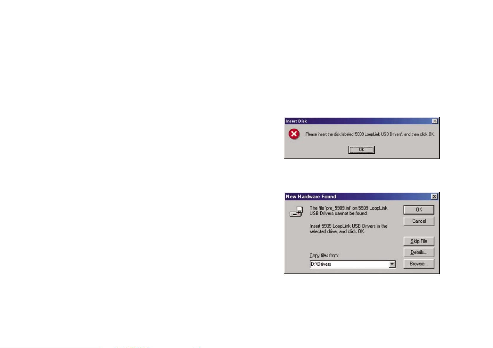
1. When Windows® 98SE and ME are searching for the drivers, the following message will probably appear:
2. After clicking OK, you will see the following dialogue where the path
”CD-ROM drive:\drivers” must be specified. Either use [Browse] or
type the path.
Installation of USB drivers for Windows
Install the USB drivers while the PReset CD is still in the drive, i.e. immediately
after the PReset installation. Please note that you need to install two USB drivers.
20 2121
20
®
98SE, ME and XP
3. The installation will then continue according to the guidelines specified in ”Installation of USB drivers for Windows
®
98SE, ME and XP”.
Page 13
Special instructions for Windows
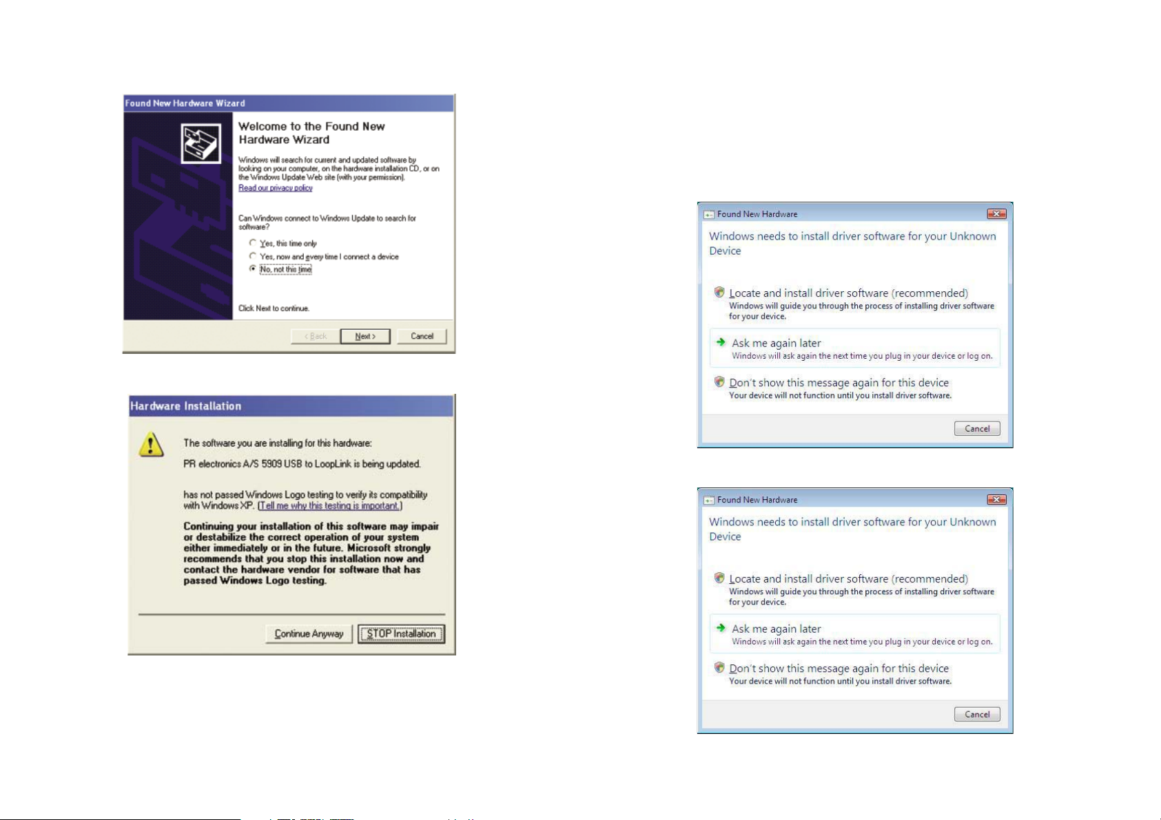
1. You must say [No, not this time] to the following dialogue:
2. You must click [Continue anyway] in the following dialogue:
®
XP:
Installation of USB drivers for Windows®Vista:
Install the USB drivers while the PReset CD is still in the drive, i.e. immediately
after the PReset installation.
1. Connect Loop Link 5909 to the USB port of the PC.
2. After a short while, the ”Found New Hardware Wizard” will be
shown. This guide will help you through the installation of the USB
driver.
3. Click [Cancel] in the following dialogue:
4. Click [Cancel] in the following dialogue:
3. The installation will then continue according to the guidelines specified in ”Installation of USB drivers for Windows
22 23
22
®
98SE, ME and XP”.
Page 14
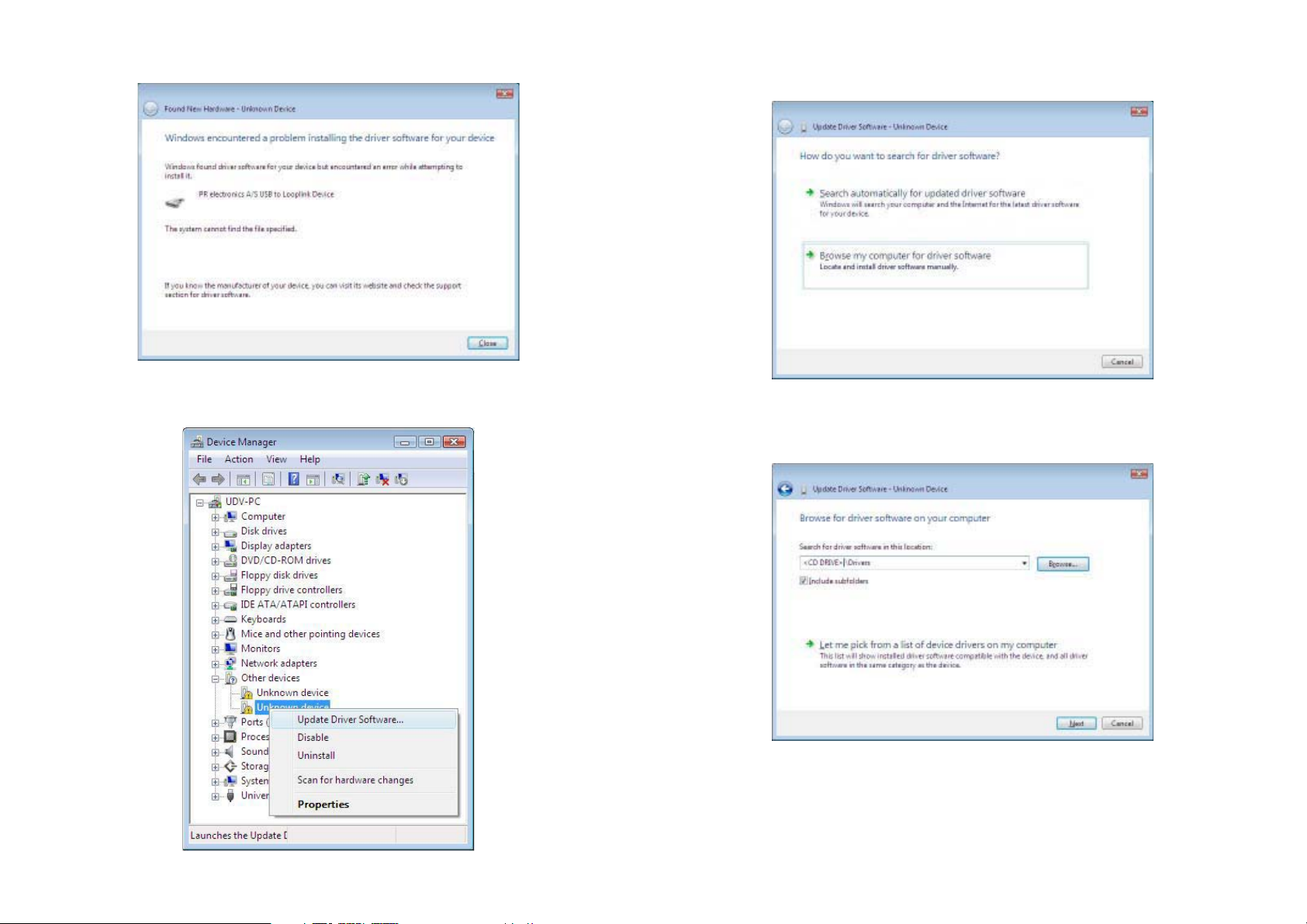
5. Click [Close] in the following dialogue:
6. Open the Device Manager and right click [Unknown device]. Then
left click [Update Driver Software].
7. Click [Browse my computer for driver software] in the following
dialogue:
8. You will see the following dialogue where the path ”CD-ROM drive:\
Drivers” must be specified. Either use [Browse] or type the path.
Then click [Next]:
24 25
Page 15
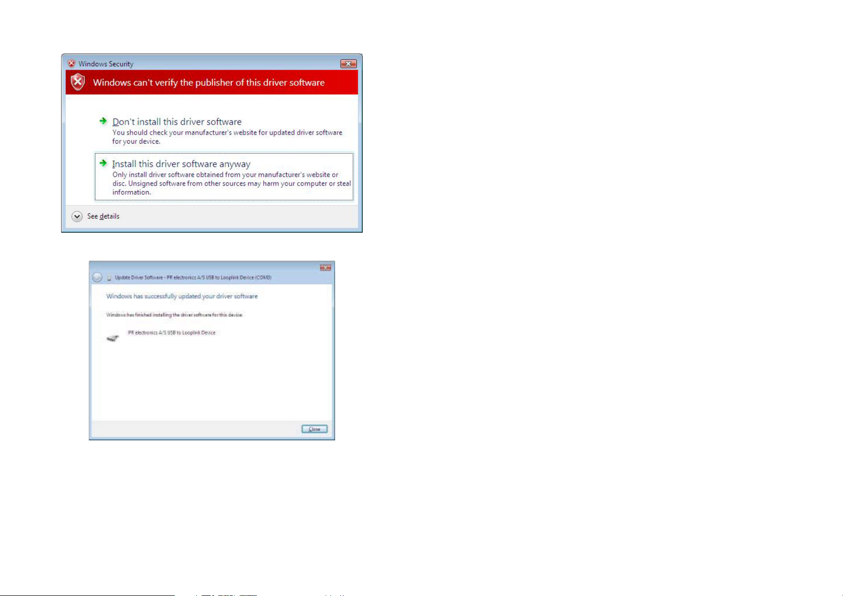
9. Click [Install this driver software anyway] in the following dialogue:
10. Click [Close] in the following dialogue:
Configuration of USB communication in PReset:
1. Start the PReset program and choose [Functions] [Set COM port],
and the ”Options” window is shown on screen.
2. Select ”Next 5909”. PReset now selects a COM port which will be
linked with the USB port to which Loop Link is connected.
3. If you want to configure Loop Link for other USB ports, you must
connect Loop Link to these ports and install the USB drivers for
each port. The other USB ports will not be linked with a COM port in
PReset until ”Next 5909” has been selected.
26 2727
Page 16
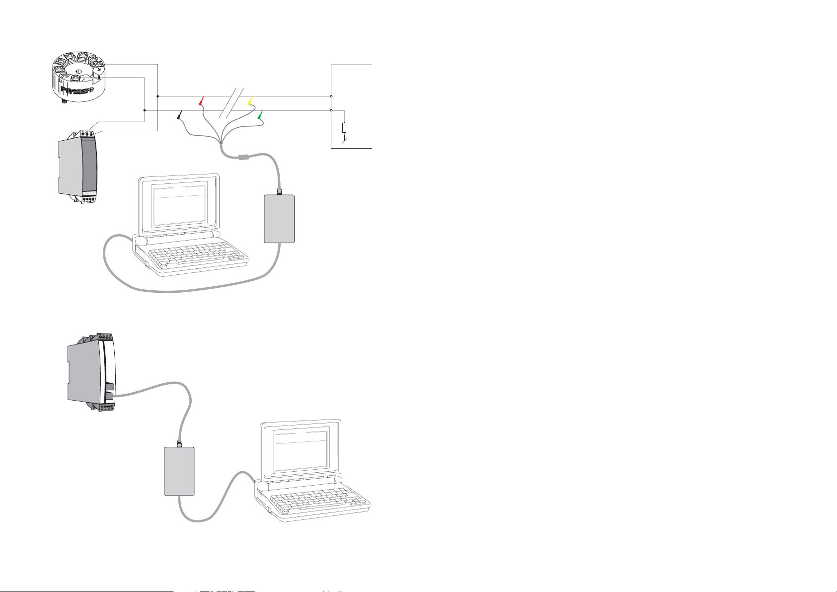
Connection of PR modules using EZ-Mini-Hooks:
INTERFACE DE COMMUNICATION USB
1
2
PR 5331, 5333, 5334, 5335
11
13
PR 6331, 6333, 6334, 6335
(21)
(23)
Black
p
O
e
g
a
u
g
n
a
L
n
o
t
i
a
c
i
n
u
m
m
o
C
t
u
p
t
u
O
t
u
p
n
I
t
c
u
d
o
r
P
e
l
1
i
3
F
3
5
p
o
t
e
R
P
0
1
-
-
8
4
0
0
2
:
e
t
a
D
4
9
5
1
0
2
3
4
0
:
o
l
n
a
i
r
e
S
s
i
c
n
o
r
t
c
l
e
e
R
P
:
o
n
g
a
T
u
p
n
i
g
o
l
a
n
A
:
e
p
y
t
t
u
p
n
I
e
g
n
a
r
t
u
p
n
I
n
i
o
t
c
e
n
n
o
C
i
o
t
c
n
u
j
d
l
o
C
t
e
s
n
o
p
s
e
R
t
u
p
t
u
o
g
o
l
a
n
A
t
:
:
c
n
e
i
m
-
4
:
e
p
y
t
t
u
p
t
u
O
C
E
/
I
I
N
D
0
0
1
t
P
U
:
r
o
r
r
e
r
o
s
n
e
S
C
0
0
.
0
5
-
0
0
.
0
e
r
i
w
-
3
-
-
-
-
-
-
:
p
m
o
c
e
s
0
0
.
1
:
Disconnect
Red
Connector
0
0
:
0
3
:
8
0
n
o
i
t
A
m
0
2
l
e
a
c
s
p
Yellow
*
Green
*
* Connected only for
on-line programming
Loop
Link
USB cable
Connection of PR modules using a modular connector:
Programming cable
with modular connector
PR 5114, 5115, 5116, 5131
n
o
i
t
p
O
e
g
a
u
g
n
a
L
n
o
t
i
a
c
i
n
u
m
m
o
C
t
u
p
t
u
O
t
u
p
n
I
t
c
u
d
o
r
P
1
e
l
i
3
3
F
5
p
o
t
e
R
P
0
1
-
-
8
4
0
0
2
:
e
t
a
D
4
9
5
1
0
2
3
4
0
:
o
n
l
a
i
r
e
S
s
c
i
n
o
r
t
c
l
e
e
R
P
:
o
n
g
a
Loop
Link
T
i
n
g
l
o
a
n
A
e
p
y
t
t
u
p
n
I
g
n
a
r
t
u
p
n
I
i
o
t
c
e
n
n
o
C
t
c
n
j
u
l
d
o
C
e
s
n
o
p
s
e
R
t
u
p
t
u
o
g
l
o
a
n
A
t
u
p
:
:
e
:
n
m
o
c
n
o
i
:
e
m
i
t
m
0
2
-
4
:
e
p
y
t
t
u
p
t
u
O
C
E
/
I
I
N
D
0
0
1
t
P
a
c
s
p
U
:
r
o
r
r
e
r
o
s
n
e
S
C
0
.
0
0
-
5
0
0
.
0
e
i
r
w
3
-
-
-
-
-
-
:
p
c
e
s
0
0
.
1
0
0
:
0
3
:
8
0
A
l
e
Receiving
Equipment
+Vsupply
Input
LOOP LINK 5909
Sommaire
Avertissements ................................................................... 30
Consignes de sécurité ....................................................... 31
Déclaration de conformité CE ............................................ 33
Application ......................................................................... 34
Caractéristiques techniques .............................................. 34
Installation .......................................................................... 34
Exigences du système ....................................................... 34
Installation de PReset ........................................................ 34
Installation de pilotes USB pour
Windows
Instructions spécifiques à Windows
Instructions spécifiques à Windows
Installation de pilotes USB pour Windows
Configuration de la communication USB dans PReset ..... 41
Connexion des modules PR
à l’aide d’un câble EZ à pinces .......................................... 42
Connexion des modules PR
à l’aide d’un connecteur modulaire ................................... 42
®
98SE, ME et XP ................................................ 34
®
98SE et ME ........ 35
®
XP ....................... 36
®
Vista ............. 37
USB cable
28 29
29
Page 17
INFORMA-
TIONS
GENERALES
TENSION
DANGE-
REUSE
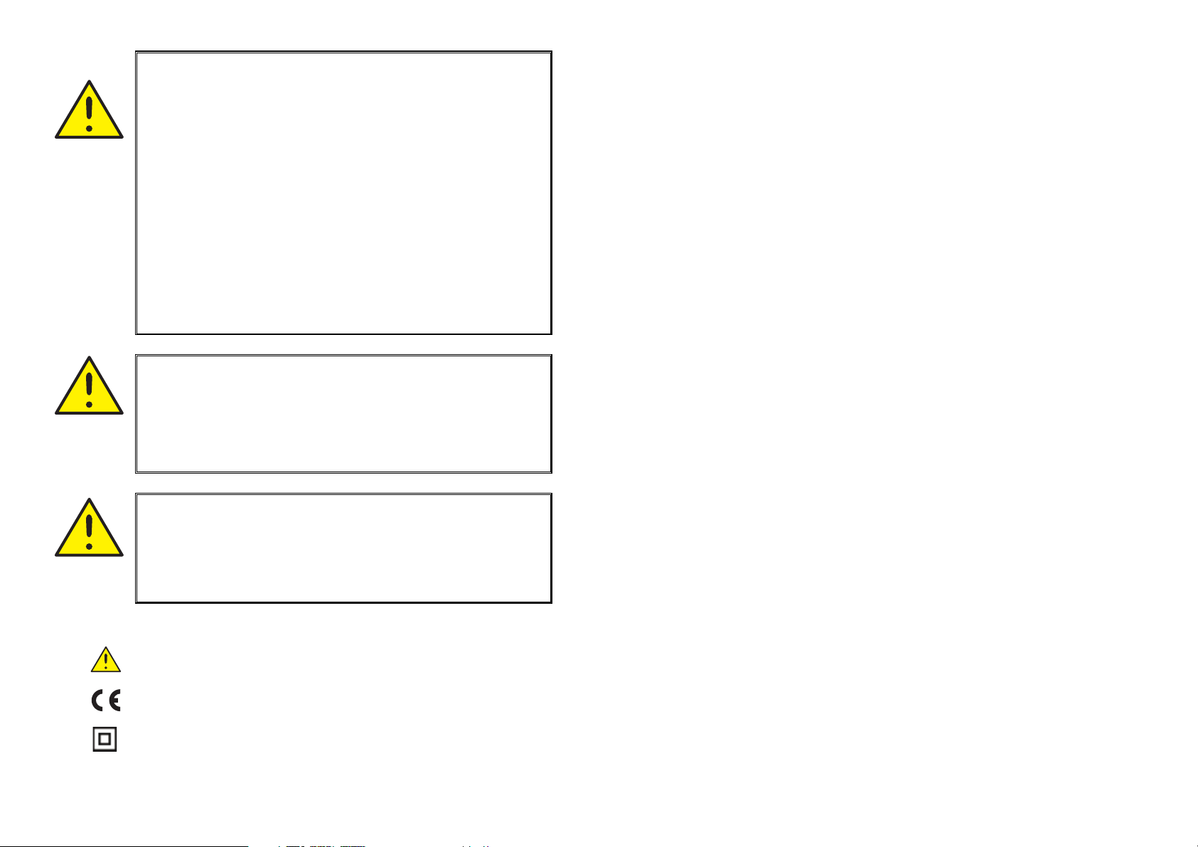
AVERTISSEMENT !
Loop Link 5909 peut à travers du câble de communication être
lié aux tensions dangereuses. Si vous ne tenez pas compte de
cet avertissement, cela peut causer des dommages corporels
ou des dégâts mécaniques.
Pour éviter les risques d’électrocution et d’incendie, conformezvous aux consignes de sécurité et suivez les instructions mentionnées dans ce guide. Vous devez vous limiter aux spécifications indiquées et respecter les instruc tions d’utilisation de ce
module, telles qu’elles sont décrites dans ce guide.
Il est nécessaire de lire ce guide attentivement avant de mettre
ce module en marche. L’installation de ce module est réservée
à un personnel qualifié (techniciens). Si la méthode d’utilisation
de l’équipement diffère de celle décrite par le fabricant, la protection assurée par l’équipe ment risque d’être altérée.
AVERTISSEMENT !
Débranchez Lopp Link 5909 du SYSTEM 5000 et du PC avant
d’effectuer l’opération suivante :
Recherche de pannes sur le module.
Seule PR electronics SARL est autorisée à réparer le module.
CONSIGNES DE SECURITE
DEFINITIONS
Les gammes de tensions dangereuses sont les suivantes: de 75 à 1500 Vcc
et de 50 à 1000 Vca. Les techniciens sont des person nes qualifiées qui sont
capables de monter et de faire fonc tionner un appareil, et d’y rechercher les
pannes, tout en respectant les règles de sécurité. Les opérateurs, connaissant
le contenu de ce guide, règlent et actionnent les boutons ou les potentiomètres
au cours des manipulations ordinaires.
RECEPTION ET DEBALLAGE
Déballez le module sans l’endommager. Le guide doit toujours être disponible
et se trouver à proximité du module. De même, il est recommandé de conserver
l’emballage du module tant que ce dernier n’est pas définitivement monté. A
la réception du module, vérifiez que le type de module reçu correspond à celui
que vous avez commandé.
ENVIRONNEMENT
N’exposez pas votre module aux rayons directs du soleil et choisissez un endroit à humidité modérée et à l’abri de la poussière, des températures élevées,
des chocs et des vibrations mécaniques et de la pluie. Le cas échéant, des
systèmes de ventilation permettent d’éviter qu’une pièce soit chauffée au-delà
des limites prescrites pour les températures ambiantes.
Tous les modules appartiennent à la catégorie d’installation Il, au degré de pollution 1 et à la classe d’isolation Il.
AVERTISSEMENT !
Le connecteur de communication femelle du SYSTEM 5000 est
relié aux borniers d’entrée sur lesquelles peuvent se produire
INSTAL-
LATION
30 31
des tensions dangereuses. Ce connecteur doit uniquement être
raccordé à Loop Link 5909 au moyen du câble inclu.
SIGNIFICATION DES SYMBOLES :
Triangle avec point d’exclamation : Attention! Si vous ne respec-
tez pas les instructions, les conséquences pourraient être fatales.
Le signe CE indique que le module est conforme aux exigences
des directives de la CE.
Ce symbole indique que le module est protégé par une isolation
double ou renforcée.
MONTAGE
Il est conseillé de réserver le raccordement du module aux techniciens qui connaissent les termes techniques, les avertis sements et les instructions de ce
guide et qui sont capables d’appliquer ces dernières.
Si vous avez un doute quelconque quant à la manipulation du module, veuillez
contacter votre distributeur local. Vous pouvez également vous adresser à
PR electronics SARL, Zac du Chêne, Activillage, 4, allée des Sorbiers, F-69673
Bron Cedex (tél. : (0) 472 140 607) ou à PR electronics A/S, Lerbakken 10, DK8410 Rønde, Danemark (tél.:+45 86 37 26 77).
3130
Page 18

PROGRAMMATION
Lors des opérations de programmation, il convient d’effectuer les mesures et les
connexions des tensions externes en respectant les spécifications mention nées
dans ce guide et dans le guide du module à être programmé.
Les techniciens doivent utiliser des outils et des instruments pouvant être manipulés en toute sécurité.
MANIPULATIONS ORDINAIRES
Les opérateurs sont uniquement autorisés à régler et faire fonctionner des modules
qui sont solidement fixés sur des platines des tableaux, etc., afin d’écarter les
risques de dommages corporels. Autrement dit, il ne doit exister aucun danger
d’électrocution et le module doit être facilement accessible.
MAINTENANCE ET ENTRETIEN
Une fois le module hors tension, prenez un chiffon humecté d’eau distillée pour
le nettoyer.
LIMITATION DE RESPONSABILITE
Dans la mesure où les instructions de ce guide ne sont pas strictement respectées par le client, ce dernier n’est pas en droit de faire une réclamation auprès
de PR electronics SARL, même si cette dernière figure dans l’accord de vente
conclu.
DECLARATION DE CONFORMITE CE
En tant que fabricant
PR electronics A/S
Lerbakken 10
DK-8410 Rønde
déclare que le produit suivant :
Type : 5909
Nom : Loop Link
correspond aux directives et normes suivantes :
La directive CEM (EMC) 2004/108/CE et les modifications subséquentes
EN 61326
Pour une spécification du niveau de rendement acceptable CEM (EMC)
renvoyer aux spécifications électriques du module.
La directive basse tension 2006/95/CE et les modifications subséquentes
EN 61010-1
Rønde, le 31 mai 2007 Peter Rasmussen
Signature du fabricant
32 3333
32
Page 19
Application :
Loop Link 5909 est une interface de communication USB pour la configuration
et la surveillance des modules PR programmables par ordinateur. La communication USB est supportée par les versions Windows
et Vista. Les modules PR disponibles dans le logiciel de configuration PReset
ver. 5.0 ou version plus récente peuvent être programmés à l’aide de Loop Link
5909.
®
98SE, ME, 2000, XP
Caractéristiques techniques :
Le CD PReset ver. 5.0 ou version plus récente contient les pilotes USB (non
signés) nécessaires à l’installation. Loop Link 5909 est alimenté par le port USB
de l’ordinateur. Si vous souhaitez économiser la batterie de votre portable, le
connecteur USB du 5909 peut être connecté à une alimentation externe. Le
connecteur de communication sur les modules PR est isolé galvaniquement de
la connexion USB de l’ordinateur.
Installation:
Exigences du système :
Windows® 98SE, ME, 2000, XP et Vista avec les recommandations suivantes :
Mémoire : 16 MB
Résolution de l’écran : 800 x 600
Espace disque dur : 12 MB
Installation de PReset :
L’interface de communication USB Loop Link 5909 ne doit être connectée au
port USB de l’ordinateur qu’après l’installation du logiciel PReset.
PReset sera installé sur votre disque dur et la base d’enregistrement sera mise
à jour. Une icône PReset sera placée automatiquement sur le bureau.
1. Introduire le CD dans le lecteur de CD-ROM et la fenêtre « Install
Shield Wizard PReset - INSTALLER » s’ouvrira automatiquement.
2. Quand le logiciel d’installation a démarré, des instructions à l’écran
vous guideront jusq’au bout de l’installation.
3. Si « AutoRun » est désactivé en Windows
cliquer sur le bouton « Démarrer », choisir [Exécuter] et faire démarrer le
logiciel d’installation « Lecteur CD :\PResetWin\setup.exe ».
®
98SE, ME, 2000, XP et Vista,
Installation des pilotes USB pour Windows® 98SE, ME, 2000 et XP :
Installer les pilotes USB pendant que le CD PReset est toujours dans le lecteur,
c.-à-d. directement après l’installation de PReset. Veuiller noter qu’il faut installer deux pilotes USB.
1. Connecter Loop Link 5909 au port USB de l’ordinateur.
2. Au bout de quelque temps l’assistant « Nouveau matériel détecté »
s’affichera. Cet assistant vous guidera jusqu’au bout de l’installation
du premier pilote USB.
3. En pressant [Exécuter] le premier pilote USB sera installé.
4. L’assistant redémarrera et vous guidera jusqu’au bout de l’installation du deuxième pilote USB.
5. En pressant [Exécuter] l’installation des pilotes USB sera terminée.
Instructions spécifiques à Windows® 98SE et ME :
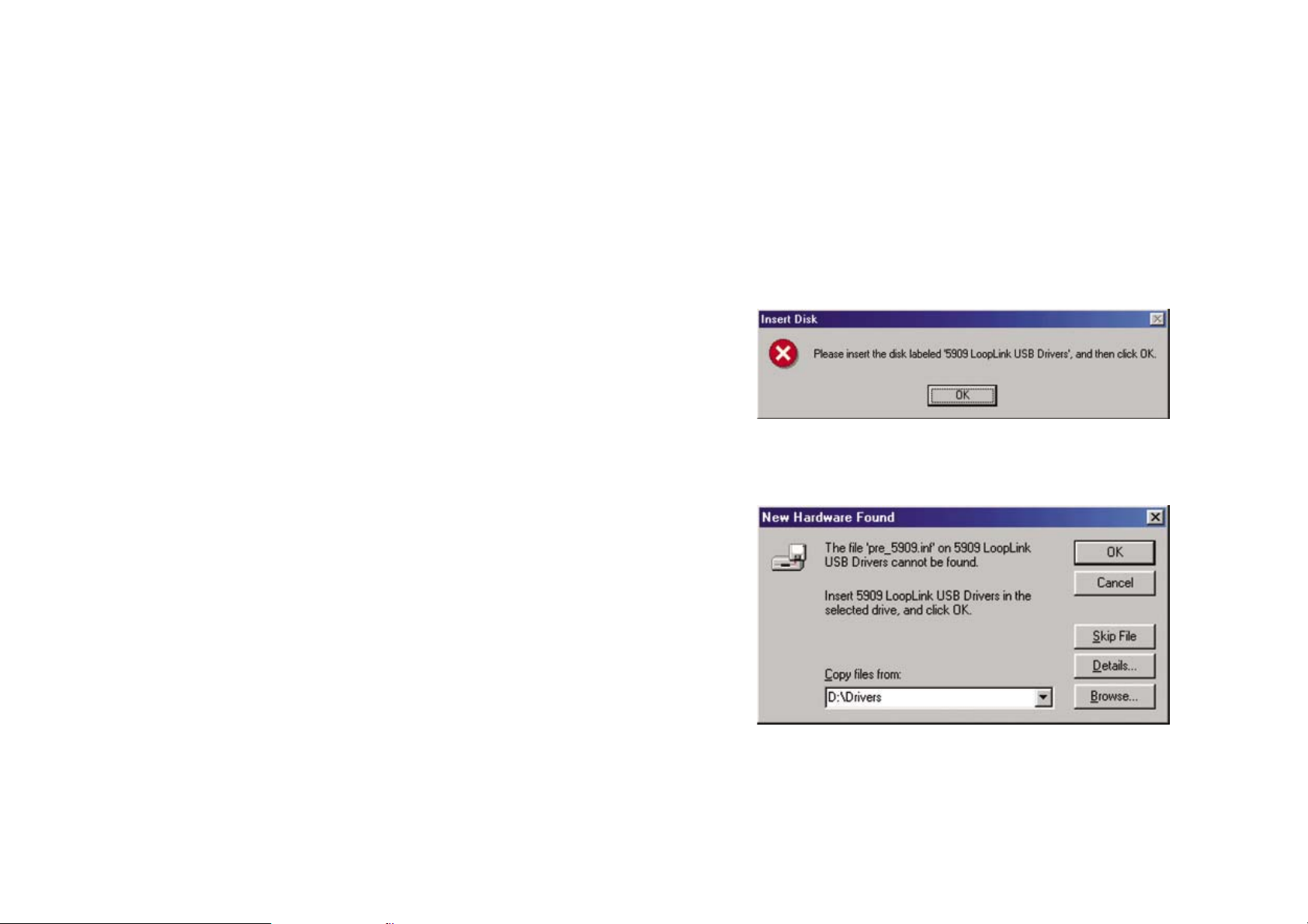
1. Quand Windows® 98SE et ME cherchent les pilotes, le message
suivant peut s’afficher :
2. Après avoir cliqué sur OK, la fenêtre suivant s’affichera et il faudra
indiquer le chemin « lecteur CD :\pilotes ». Utiliser [ Rechercher ] ou
taper le chemin d’accès.
3. Le reste de l’installation se déroule selon les indications sous « Installation des pilotes USB pour Windows
®
98SE, ME, 2000 et XP ».
34 3535
34
Page 20
Instructions spécifiques à Windows® XP :
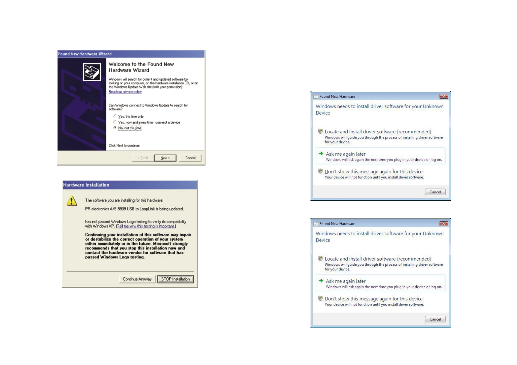
1. Avec Windows® XP il faut dire «[ Non, pas cette fois ] à l’avertissement suivant :
2. Il faut cliquer sur [ Continuer malgré tout ] dans la fenêtre suivant :
Installation des pilotes USB pour Windows
Installer les pilotes USB pendant que le CD PReset est toujours dans le lecteur,
c.-à-d. directement après l’installation de PReset.
1. Connecter Loop Link 5909 au port USB de l’ordinateur.
2. Au bout de quelque temps ” l’Assistant nouveau matériel détecté ”.
s’affichera. Cet assistant vous guidera jusqu’au bout de l’installation
du premier pilote USB.
3. Cliquer sur [ Annuller ] dans la fenêtre suivant :
®
Vista
4. Cliquer sur [ Annuller ] dans la fenêtre suivant :
3. Le reste de l’installation se déroule selon les indications sous « Installation des pilotes USB pour Windows
36 37
36
®
98SE, ME, 2000 et XP ».
Page 21
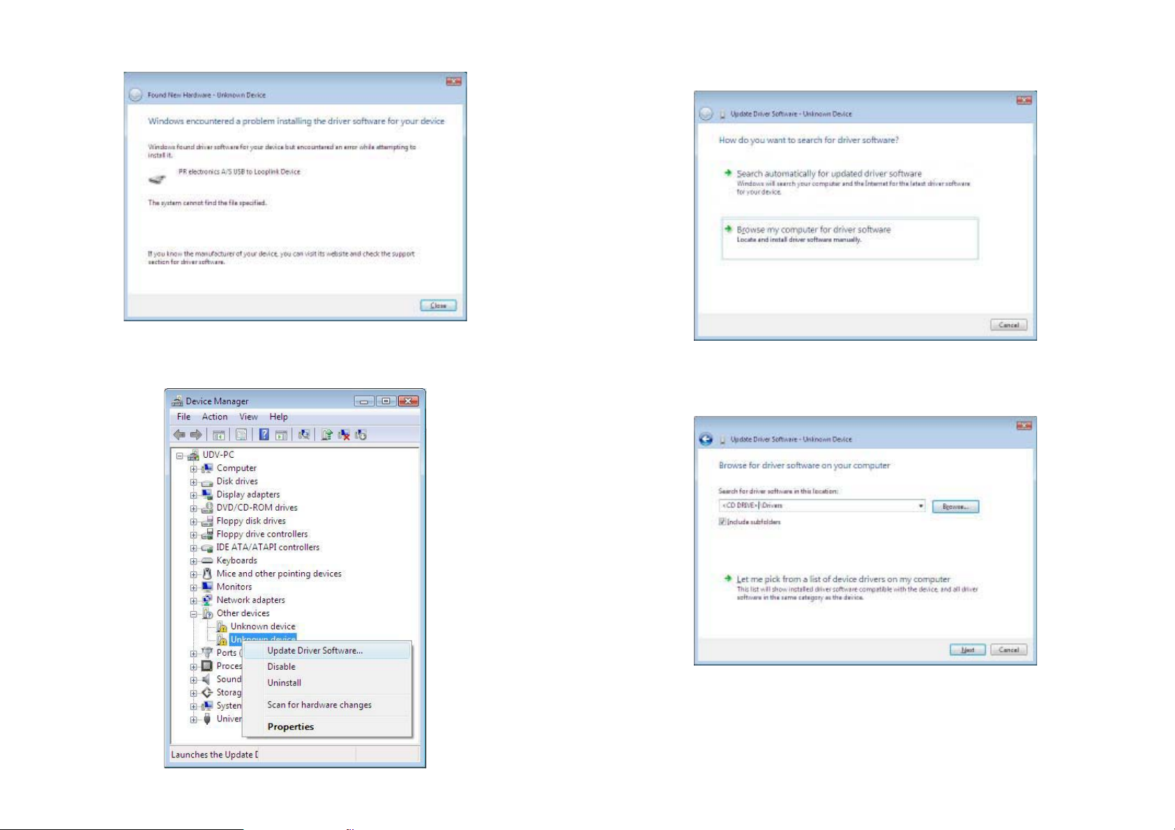
5. Cliquer sur [ Fermer ] dans la fenêtre suivant :
6. Ouvrir le gestionnaire d’appareils et cliquer avec le bouton droit sur
[ Périphérique inconnu ]. Cliquer ensuite avec le bouton gauche sur
[ Mettre à jour le programme pilote ].
7. Cliquer sur [ Rechercher un programme pilote sur mon ordinateur ]
dans la fenêtre suivant :
8. Dans la fenêtre suivant il faut indiquer le chemin
« lecteur CD :\pilotes ». Utiliser [ Rechercher ] ou taper le chemin
d’accès. Après avoir indiqué le chemin cliquer sur [ Suivant ]
38 39
Page 22
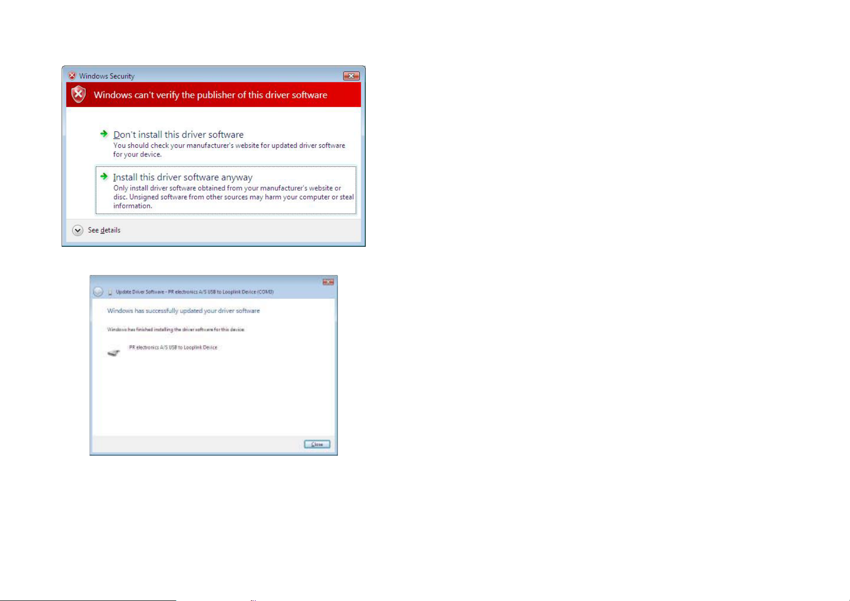
9. Cliquer sur [ Installer malgré tout ce programme pilote ] dans la
fenêtre suivant :
10. Cliquer sur [ Fermer ] dans la fenêtre suivant :
Configuration de la communication USB dans PReset :
1. Démarrer le logiciel PReset et sélectionner [ Outils ] [Choisir port de
communication ], et la fenêtre « Options port COM » s’affichera sur
l’écran.
2. Sélectionner « Next 5909 ». PReset sélectionne maintenant un port
COM qui sera lié au port USB auquel Loop Link est connecté.
3. Si vous souhaitez configurer Loop Link pour d’autres ports USB,
il faut connecter Loop Link à ces ports et installer les pilotes USB
pour chaque port. Les autres ports USB ne seront liés à un port
COM dans PReset qu’après sélection de « Next 5909 ».
40 4141
Page 23
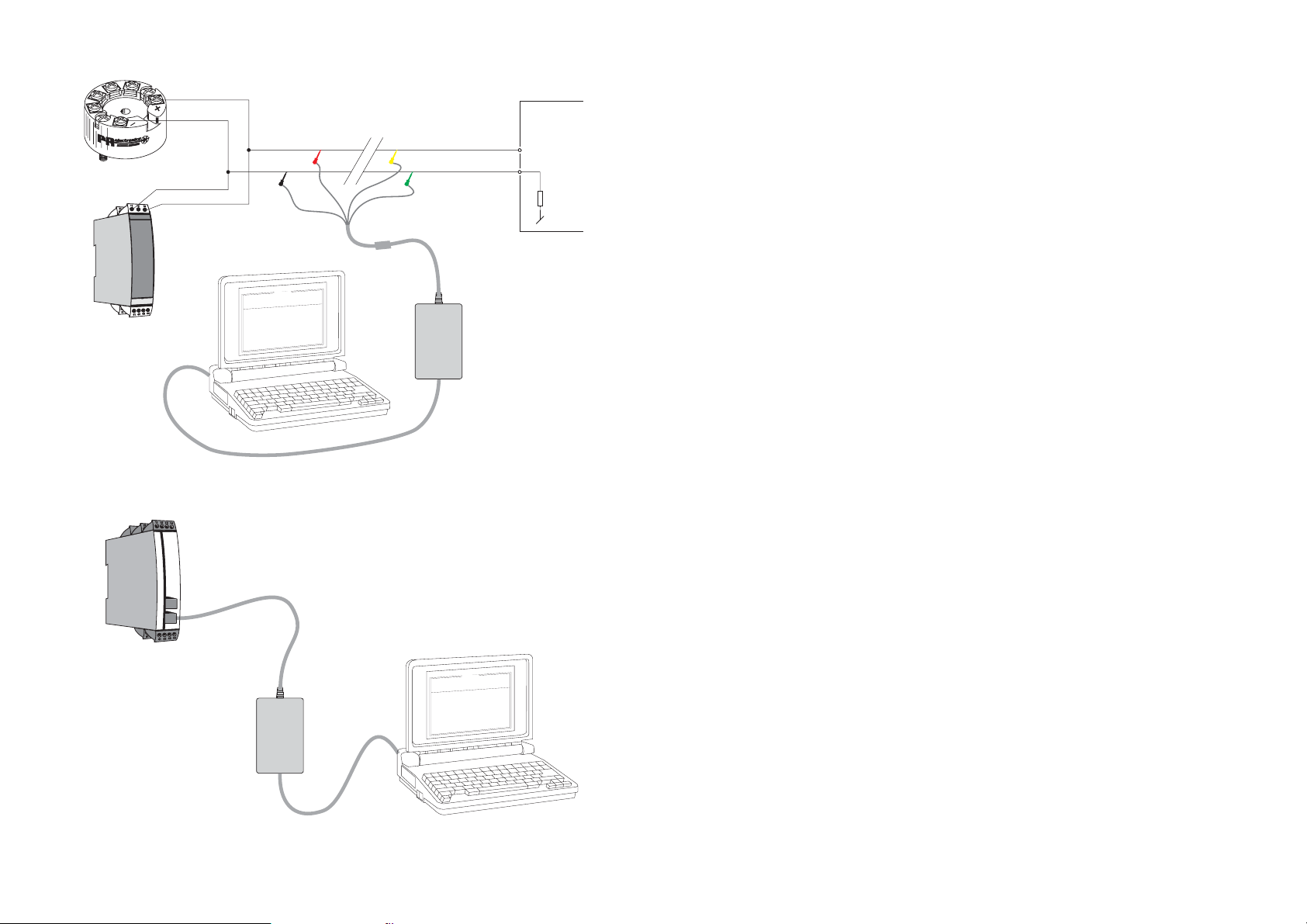
Connexion des modules PR à l’aide d’un câble EZ à pinces :
USB-KOMMUNIKATIONSINTERFACE
1
2
Débranché
API ou autres
+Valim.
Jaune
*
*
Entrée
Vert
* Connexion facultative
Loop
PR 5331, 5333, 5334, 5335
11
13
PR 6331, 6333, 6334, 6335
(21)
(23)
Rouge
Noir
Connecteur
0
0
:
0
3
:
8
0
n
o
i
t
p
O
e
g
a
u
g
n
a
L
n
o
t
i
a
c
i
n
u
m
m
o
C
t
u
p
t
u
O
t
u
p
n
I
t
c
u
d
o
r
P
e
l
1
i
3
F
3
5
p
o
t
e
R
P
0
1
-
-
8
4
0
0
2
:
e
t
a
D
4
9
5
1
0
2
3
4
0
:
o
l
n
a
i
r
e
S
s
i
c
n
o
r
t
c
l
e
e
R
P
:
o
n
g
a
T
p
n
i
g
o
l
a
n
A
:
e
p
y
t
t
u
p
n
I
e
g
n
a
r
t
u
p
n
I
n
i
o
t
c
e
n
n
o
C
i
o
t
c
n
u
j
d
l
o
C
t
e
s
n
o
p
s
e
R
t
u
p
t
u
o
g
o
l
a
n
A
t
u
:
:
:
p
m
o
c
n
:
e
i
m
A
m
0
2
-
4
:
e
p
y
t
t
u
p
t
u
O
C
E
/
I
I
N
D
0
0
1
t
P
l
e
a
c
s
p
U
:
r
o
r
r
e
r
o
s
n
e
S
C
0
0
.
0
5
-
0
0
.
0
e
r
i
w
-
3
-
-
-
-
-
c
e
s
0
0
.
1
Link
Câble USB
Connexion des modules PR à l’aide d’un connecteur modulaire :
Câble de programmation
avec connecteur modulaire
LOOP LINK 5909
Inhaltsverzeichnis
Warnungen ......................................................................... 44
Sicherheitsregeln ................................................................ 45
EG-Konformitätserklärung.................................................. 47
Anwendung ........................................................................ 48
Technische Merkmale ......................................................... 48
Installation .......................................................................... 48
Systemanforderungen ........................................................ 48
Installation von PReset ....................................................... 48
Installation von USB Treibern für
Windows
Zu beachten unter Windows
Zu beachten unter Windows
Installation von USB Treibern für Windows
Konfiguration der USB Kommunikation im PReset ........... 55
Anschluss der PR Geräte mittels EZ-Mini-Harken ............. 56
Anschluss der PR Geräte mittels dem modularen Stecker 56
®
98SE, ME et XP ................................................ 48
®
98SE und ME ................. 49
®
XP .................................. 50
®
Vista ............ 51
PR 5114, 5115, 5116, 5131
0
0
:
0
3
:
8
0
n
o
i
t
p
O
e
g
a
u
g
n
a
L
n
o
i
t
a
c
i
n
u
m
m
o
C
t
u
p
t
u
O
t
u
p
n
I
t
c
u
d
o
r
P
1
e
l
i
3
F
3
5
p
o
t
e
R
P
0
1
-
-
8
4
0
0
2
:
e
t
a
D
4
9
5
1
0
2
3
4
0
:
o
n
l
a
r
i
e
S
s
c
i
n
o
r
t
c
l
e
e
R
P
:
o
n
g
a
T
i
n
g
l
o
a
n
A
e
p
y
t
t
u
p
n
I
g
n
a
r
t
u
p
n
I
i
o
t
c
e
n
n
o
C
t
c
n
j
u
l
d
o
C
e
s
n
o
p
s
e
R
t
u
p
t
u
o
g
l
o
a
n
A
t
u
p
:
:
e
:
n
:
p
m
o
c
n
o
i
:
e
m
i
t
A
m
0
2
-
4
:
e
p
y
t
t
u
p
t
u
O
C
E
/
I
I
N
D
0
0
1
t
P
l
e
a
c
s
p
U
:
r
o
r
r
e
r
o
s
n
e
S
C
0
.
0
0
-
5
0
0
.
0
e
i
r
w
3
-
-
-
-
-
c
e
s
0
0
.
1
Loop
Link
Câble USB
42 43
43
Page 24
ALLGE-
MEINES
GEFÄHR-
LICHE
SPANNUNG
INSTAL-
LATION
WARNUNG
Dieses Modul kann beim Anschluss durch das Kommunikationskabel an das SYSTEM 5000 in Verbindung mit lebensgefährlicher elektrischer Spannung kommen. Missachtung dieser
Warnung kann zu schweren Verletzungen oder mechanischer
Zerstörung führen. Um eine Gefährdung durch Stromstöße oder
Brand zu vermeiden müssen die Sicherheitsregeln des Handbuches eingehalten, und die Anweisungen befolgt werden. Die
Spezifikationswerte dürfen nicht überschritten werden, und das
Modul darf nur gemäß folgender Beschreibung benutzt werden.
Das Handbuch ist sorgfältig durchzulesen, ehe das Modul in
Gebrauch genommen wird. Nur qualifizierte Personen (Techniker) müssen dieses Modul benutzen. Wenn das Modul nicht
wie in diesem Handbuch beschrieben benutzt wird, werden die
Schutzeinrichtungen des Moduls beeinträchtigt.
WARNUNG
Die folgenden Arbeiten müssen am Modul nur dann ausgeführt
werden, wenn das Kommunikationskabel keine Verbindung mit
dem SYSTEM 5000 und dem PC hat:
Fehlersuche am Modul.
Reparaturen am Modul müssen nur von PR electronics A/S
ausgeführt werden.
WARNUNG
Der Verbindungssteckbuchse im SYSTEM 5000 ist an
Eingangsterminale angeschlossen, in denen gefährliche Spannungen auftreten können, und ein Anschluss an die Programmierungseinheit Loop Link 5909 ist nur über das festmontierte
Kommunikationskabel zulässig.
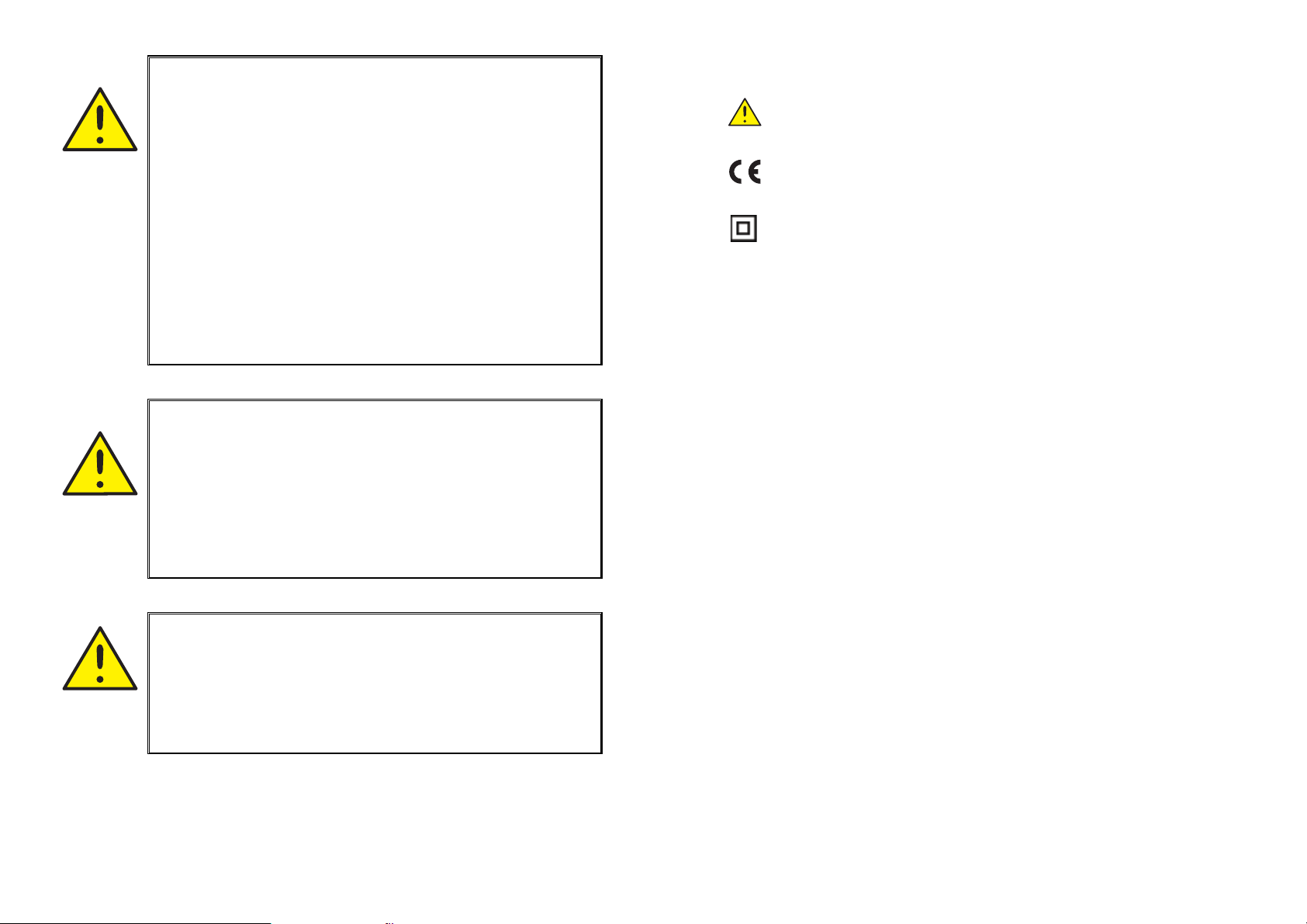
ZEICHENERKLÄRUNGEN:
Dreieck mit Ausrufungszeichen: Warnung/Vorschrift. Vorgänge,
die zu lebensgefährlichen Situationen führen können.
Die CE-Marke ist das sichtbare Zeichen dafür, dass das Modul
die EU-Vorschriften erfüllt.
Doppelte Isolierung ist das Symbol dafür, dass das Modul
besondere Anforderungen an die Isolierung erfüllt.
SICHERHEITSREGELN
DEFINITIONEN:
Gefährliche Spannungen sind definitionsgemäß die Bereiche: 75...1500 Volt
Gleichspannung und 50...1000 Volt Wechselspannung.
Techniker sind qualifizierte Personen, die dazu ausgebildet oder angelernt sind,
eine Installation, Bedienung oder evtl. Fehlersuche auszuführen, die
sowohl technisch als auch sicherheitsmäßig vertretbar ist.
Bedienungspersonal sind Personen, die im Normalbetrieb mit dem Produkt die
Drucktasten oder Potentiometer des Produktes einstellen bzw. bedienen und
die mit dem Inhalt dieses Handbuches vertraut gemacht wurden.
EMPFANG UND AUSPACKEN:
Packen Sie das Modul aus, ohne es zu beschädigen und sorgen Sie dafür, dass
das Handbuch stets in der Nähe des Moduls und zugänglich ist.
Die Verpackung sollte beim Modul bleiben, bis dieses am endgültigen Platz
montiert ist.
Kontrollieren Sie beim Empfang, ob der Modultyp Ihrer Bestellung entspricht.
UMGEBUNGSBEDINGUNGEN:
Direkte Sonneneinstrahlung, starke Staubentwicklung oder Hitze, mechanische
Erschütterungen und Stöße sind zu vermeiden; das Modul darf nicht Regen
oder starker Feuchtigkeit ausgesetzt werden. Bei Bedarf muss eine Erwärmung,
welche die angegebenen Grenzen für die Umgebungstemperatur überschreitet,
mit Hilfe eines Kühlgebläses verhindert werden.
Alle Module gehören der Installationskategorie II, dem Verschmutzungsgrad 1
und der Isolationsklasse II an.
44 45
4544
Page 25

INSTALLATION:
Das Modul darf nur von Technikern angeschlossen werden, die mit den
technischen Ausdrücken, Warnungen und Anweisungen im Handbuch vertraut
sind und diese befolgen.
Sollten Zweifel bezüglich der richtigen Handhabung des Moduls bestehen,
sollte man mit dem Händler vor Ort Kontakt aufnehmen. Sie können aber auch
direkt mit PR electronics GmbH, Bamlerstraße 92, D-45141 Essen, (Tel.: (0) 201
860 6660) oder mit PR electronics A/S, Lerbakken 10, DK-8410 Rønde, Dänemark (Tel. : +45 86 37 26 77) Kontakt aufnehmen.
PROGRAMMIERUNG:
Während der Programmierung müssen Messung und Anschluss externer Spannungen entsprechend dieser Betriebsanleitung und der Betriebsanleitung für
die zu programmierende Einheit ausgeführt werden. Der Techniker muss hierbei
sicherheitsmäßig einwandfreie Werkzeuge und Instrumente benutzen.
BEDIENUNG IM NORMALBETRIEB:
Das Bedienungspersonal darf die Module nur dann einstellen oder bedienen,
wenn diese auf vertretbare Weise in Schalttafeln o. ä. fest installiert sind, so
dass die Bedienung keine Gefahr für Leben oder Material mit sich bringt. D. h.,
es darf keine Gefahr durch Berührung bestehen, und das Modul muss so plaziert sein, dass es leicht zu bedienen ist.
EG-KONFORMITÄTSERKLÄRUNG
Als Hersteller bescheinigt
PR electronics A/S
Lerbakken 10
DK-8410 Rønde
hiermit für das folgende Produkt:
Typ: 5909
Name: Loop Link
die Konformität mit folgenden Richtlinien und Normen:
EMV Richtlinien 2004/108/EG und nachfolgende Änderungen
EN 61326
Zur Spezifikation des zulässigen Erfüllungsgrades, siehe die Elektrische Daten
des Moduls.
Die Niederspannungsrichtlinien 2006/95/EG und nachfolgende Änderungen
EN 61010-1
REINIGUNG:
Das Modul darf in spannungslosem Zustand mit einem Lappen gereinigt werden, der mit destilliertem Wasser leicht angefeuchtet ist.
HAFTUNG:
In dem Umfang, in welchem die Anweisungen dieses Handbuches nicht
genau eingehalten werden, kann der Kunde PR electronics gegenüber keine
Ansprüche geltend machen, welche ansonsten entsprechend der eingegangenen Verkaufsvereinbarungen existieren können.
46 4747
46
Rønde, 31. Mai 2007 Peter Rasmussen
Unterschrift des Herstellers
Page 26
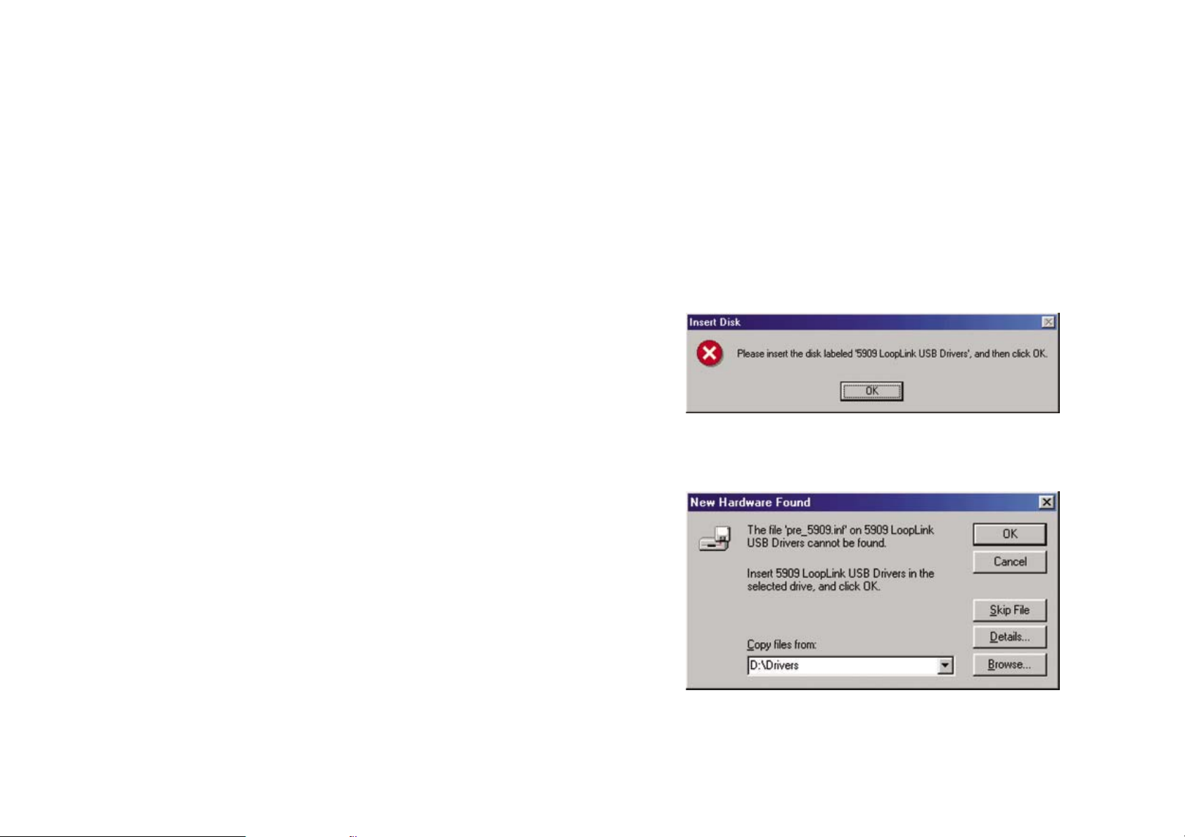
Anwendung:
Loop Link 5909 ist ein USB Kommunikations-Interface zur Konfiguration und
Überwachung von PC-programmierbaren Geräten von PR electronics. Die USB
Kommunikation wird unterstützt von den Windows
XP und Vista. PR Geräte, welche im Konfigurationsprogramm PReset Vers. 5.0
oder höher, verfügbar sind, können mit Loop Link 5909 programmiert werden.
®
Versionen 98SE, ME, 2000,
Technische Merkmale:
Die PC Programm CD PReset, Vers. 5.0 oder höher, beinhaltet die benötigten
(unsignierte) USB Treiber. Loop Link 5909 wird über den USB Port versorgt.
Wenn Sie beim Labtop Energie sparen wollen, kann die USB Schnittstelle des
5909 an einen extern versorgten Hub angeschlossen werden. Der Kommunikations-Steckverbinder an den PR Geräten ist von der USB Verbindung des PCs
galvanisch getrennt.
Installation:
Systemanforderungen:
Windows® 98SE, ME, 2000, XP und Vista mit folgenden Empfehlungen:
Speicher: 16 MB
Bildschirm Auflösung: 800 x 600
Freier Festplattenspeicher: 12 MB
unmittelbar nach der PReset Installation. Bitte achten Sie darauf, dass Sie zwei
USB Treiber installieren müssen.
1. Verbinden Sie Loop Link 5909 mit dem USB Port des PCs.
2. Nach kurzer Zeit wird das Fenster „ Neue Hardware gefunden“
geöffnet. Diese Anleitung führt Sie durch die Installation des ersten
USB Treibers.
3. Klicken Sie [Ausführen] an und der erste USB Treiber wird installiert.
4. Die Anweisung startet erneut und führt Sie durch die Installation des
Zweiten USB Treibers.
5. Klicken Sie [Ausführen] an und die USB Treiber-Installation ist komplett.
Zu beachten unter Windows®98SE und ME:
1. Wenn Windows® 98SE und ME die Treiber suchen, wird das folgende Fenster erscheinen:
Installation von Preset:
Das USB Kommunikations Inteface Loop Link 5909 darf NICHT mit dem USB
Port des PCs verbunden sein, bis die Installation von PReset abgeschlossen ist.
PReset wird auf der Festplatte installiert und die Registrierung wird mit allen
benötigten Informationen aktualisiert. Ein PReset Icon wird automatisch auf den
Desktop positioniert.
1. Legen Sie die CD-Rom in das entsprechende Laufwerk und der
Dialog “InstallShield Wizard PReset – INSTALL“ wird automatisch
gestartet.
2. Wenn das Programm gestartet wird, führt Sie ein On-Screen Leitfaden durch die Installation.
3. Wenn AutoRun im Windows
ausgeschaltet ist, klicken Sie auf den „Start“ Button, wählen
Sie „Ausführen“ und starten Sie die Installation über den Pfad
„<Laufwerksbuchstabe>:\ PResetWin\setup.exe“
®
98SE, ME, 2000, XP und Vista
Installation von USB Treibern für Windows® 98SE, ME, 2000 und XP:
Installieren Sie die USB Treiber während die PReset CD im Laufwerk ist, d.h.
48 4949
48
2. Nach Bestätigung mit „ok“, erscheint folgendes Feld “CD-ROM
drive:/drivers“, welches spezifiziert werden muss. Andernfalls
„Durchsuchen“ oder Pfad eingeben.
3. Die Installation wird anschließend fortgesetzt gemäß den Anweisungen der „Installation von USB Treibern für Windows
und XP“.
®
98SE, ME, 2000
Page 27
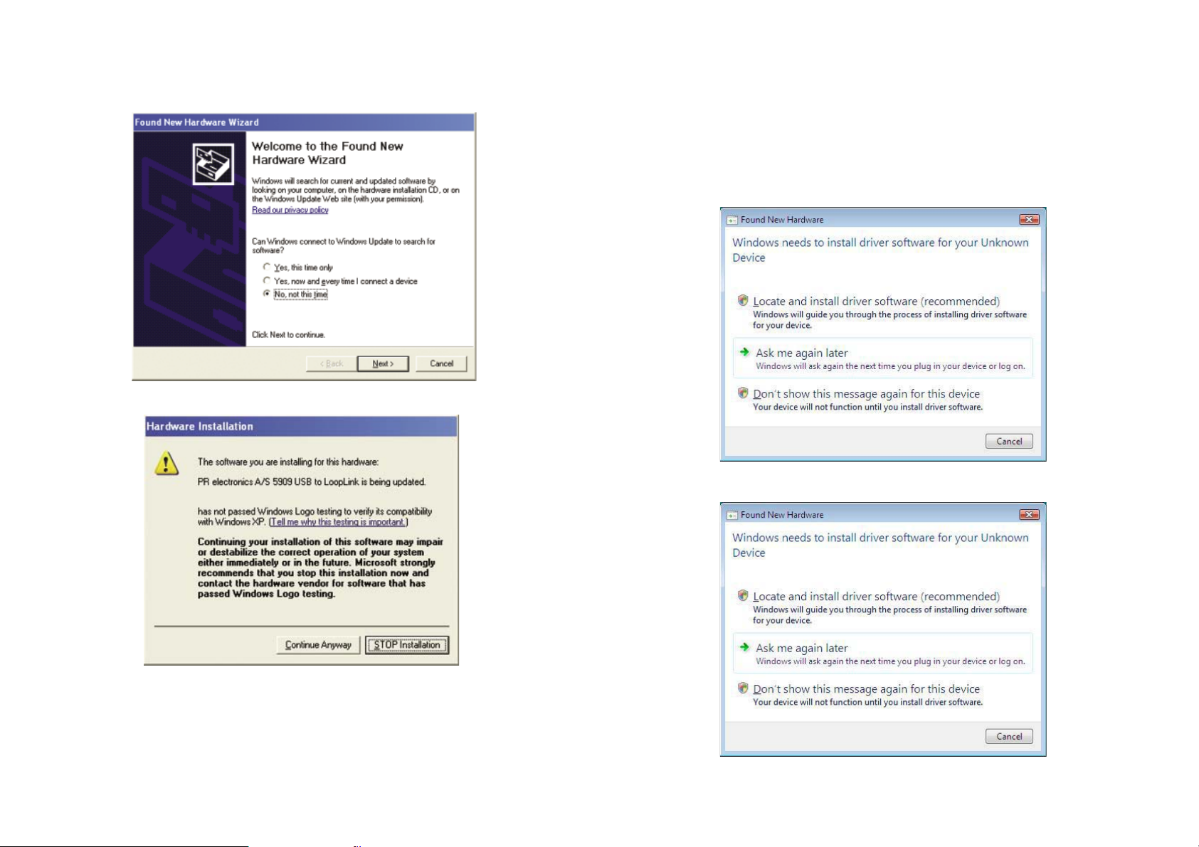
Zu beachten unter Windows®XP:
1. Sie müssen beim folgenden Dialog „Nein, nicht dieses mal“ anklicken.
2. Sie müssen „weiter“ beim folgenden Dialog anklicken.
Installation von USB Treibern für Windows®Vista
Installieren Sie die USB Treiber während die PReset CD im Laufwerk ist, d.h.
unmittelbar nach der PReset Installation.
1. Verbinden Sie Loop Link 5909 mit dem USB Port des PCs.
2.Nach kurzer Zeit wird das Fenster ”Neue Hardwarekomponente
gefunden” geöffnet. Diese Anleitung führt Sie durch die Installation
des ersten USB Treibers.
3. Klicken Sie [Abbrechen] beim folgenden Dialog:
4. Klicken Sie [Abbrechen] beim folgenden Dialog:
3. Die Installation wird anschließend fortgesetzt gemäß den Anweisungen der „Installation von USB Treibern für Windows
und XP“.
50 51
50
®
98SE, ME, 2000
Page 28
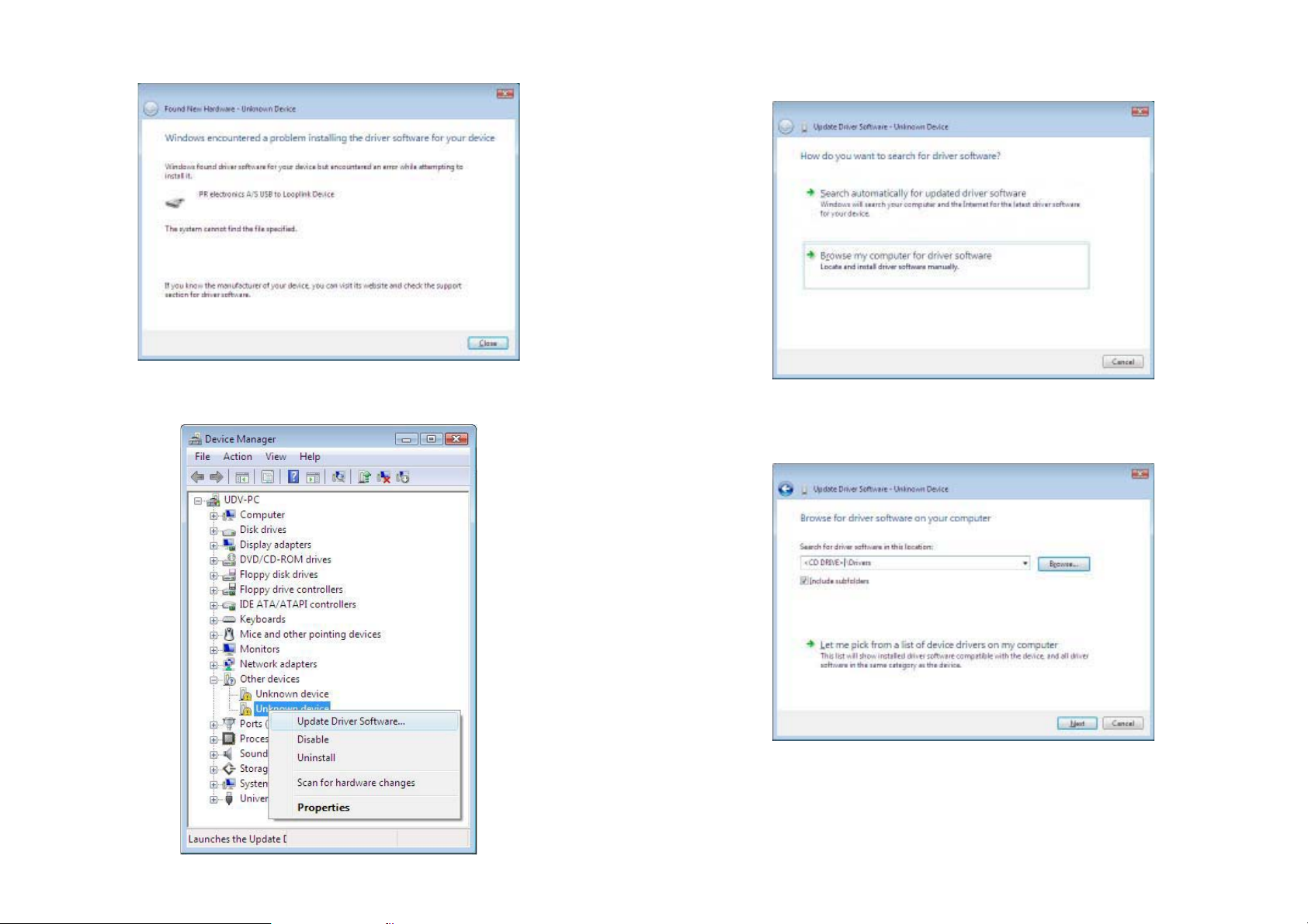
5. Klicken Sie [Schließen] beim folgenden Dialog:
6. Öffnen Sie der Gerätemanager und rechtsklicken Sie [Unbekanntes
Gerät]. Linksklicken Sie danach [Treiber aktualisieren].
7. Klicken Sie [Meinen Computer nach Treibersoftware durchsuchen]
beim folgenden Dialog:
8. Beim folgenden Diaglog muss der Pfad ”CD-ROM-drive:\drivers”
spezifiziert werden. Andernfalls „Durchsuchen“ oder Pfad eingeben.
Klicken Sie danach [Weiter].
52 53
Page 29
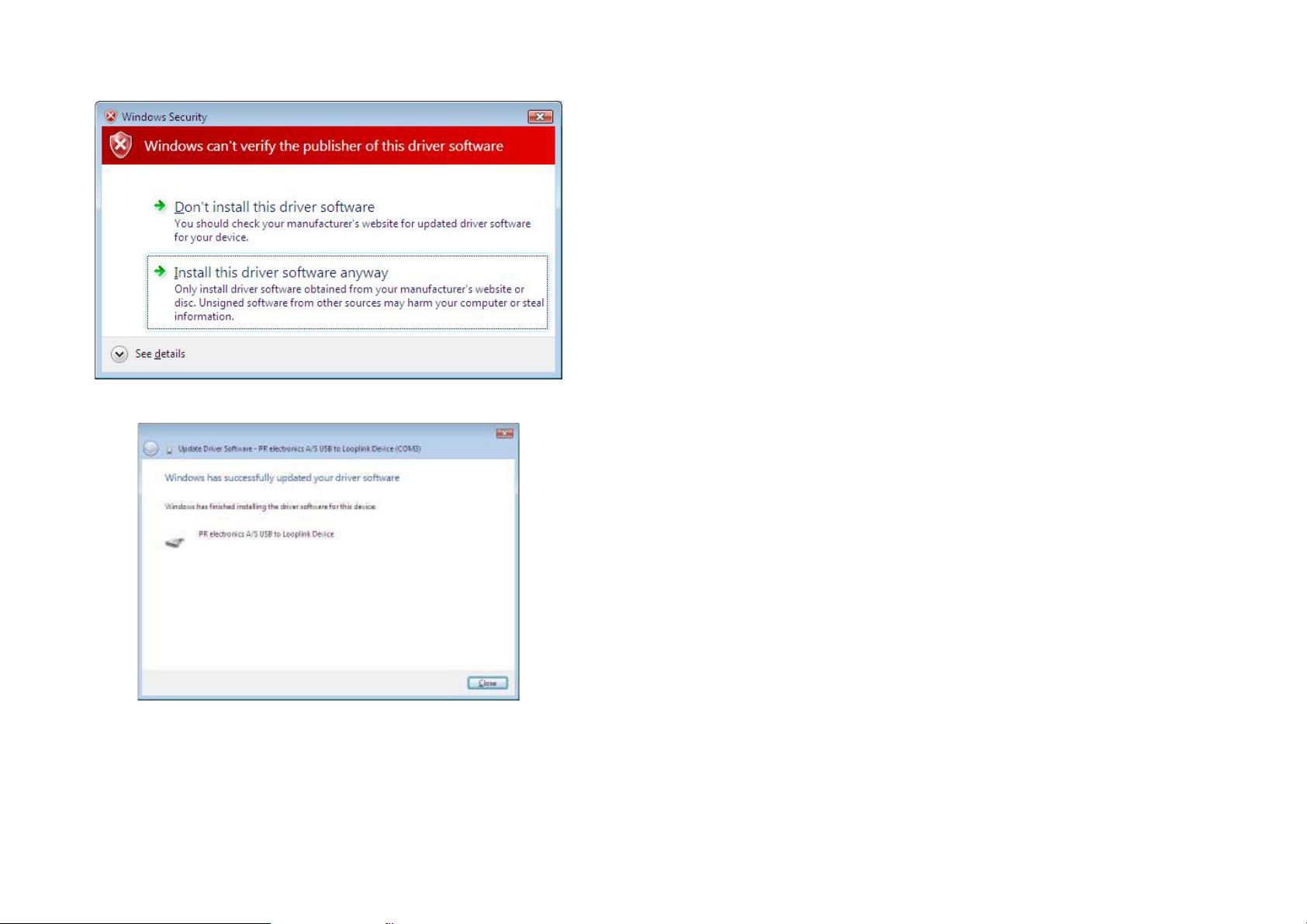
9. Klicken Sie [Installation dieser Treibersoftware fortsetzen] beim
folgenden Dialog:
10. Klicken Sie [Schließen] beim folgenden Dialog:
Konfiguration der USB Kommunikation in PReset:
1. Starten Sie das PReset Programm und wählen Sie unter [Extras]
[COM-Kanal auswählen], und das Fenster „COM-Kanal“ wird geöffnet.
2. Wählen Sie “Next 5909”, PReset wählt jetzt ein COM Port aus, welches mit dem USB Port des Loop Links verbunden ist.
3. Wenn Sie Loop Link für andere USB Anschlüsse konfigurieren
möchten, müssen Sie Loop Link entsprechend an diesem Port
anschließen und die USB Treiber für jedes Port installieren. Die anderen USB Anschlüsse werden nicht mit dem COM Port in PReset
verbunden solange „Next 5909“ nicht angewählt wurde.
54 5555
Page 30
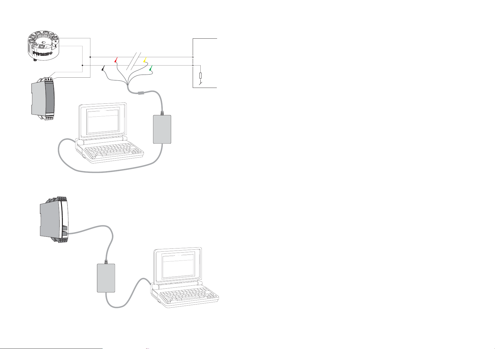
Anschluss der PR Geräte mittels EZ-Mini-Harken:
1
2
PR 5331, 5333, 5334, 5335
11
13
PR 6331, 6333, 6334, 6335
(21)
(23)
Schwarz
O
t
u
p
n
I
t
c
u
d
o
r
P
e
l
i
F
:
e
t
a
D
0
:
o
l
n
a
i
r
e
S
e
R
P
:
o
n
g
a
T
t
u
p
n
i
g
o
l
a
n
A
:
e
p
y
t
t
u
p
n
I
:
e
g
n
a
r
t
u
p
n
I
:
n
i
o
t
c
e
n
n
o
C
m
o
c
n
i
o
t
c
n
u
j
d
l
o
C
:
e
i
m
t
e
s
n
o
p
s
e
R
p
O
e
g
a
u
g
n
a
L
n
o
t
i
a
c
i
n
u
m
m
o
C
t
u
p
t
u
1
3
3
5
p
o
t
e
R
P
0
1
-
-
8
4
0
0
2
4
9
5
1
0
2
3
4
s
i
c
n
o
r
t
c
l
e
t
u
p
t
u
o
g
o
l
a
n
A
4
:
e
p
y
t
t
u
p
t
u
O
C
E
/
I
I
N
D
0
0
1
t
P
U
:
r
o
r
r
e
r
o
s
n
e
S
C
0
0
.
0
5
-
0
0
.
0
e
r
i
w
-
3
-
-
-
-
-
-
:
p
c
e
s
0
0
.
1
Rot
0
0
:
0
3
:
8
0
n
o
i
t
A
m
0
2
l
e
a
c
s
p
Unterbrechen
*
Anschlussstelle
Gelb
*
Grün
Loop
* Nur anzuschliessen,
wenn on-line (im Betrieb)
konfiguriert werden soll.
Link
USB-Kabel
Anschluss der PR Geräte mittels dem modularen Stecker:
Betriebsspannung
B
+V
Eingang
PR 5114, 5115, 5116, 5131
56
Programmierkabel
mit Modularstecker
Loop
Link
USB-Kabel
0
0
:
0
3
:
8
0
n
o
i
t
p
O
e
g
a
u
g
n
a
L
n
o
i
t
a
c
i
n
u
m
m
o
C
t
u
p
t
u
O
t
u
p
n
I
t
c
u
d
o
r
P
1
e
l
i
3
F
3
5
p
o
t
e
R
P
0
1
-
-
8
4
0
0
2
:
e
t
a
D
4
9
5
1
0
2
3
4
0
:
o
n
l
a
i
r
e
S
s
c
i
n
o
r
t
c
l
e
e
R
P
:
o
n
g
a
T
i
n
g
l
o
a
n
A
e
p
y
t
t
u
p
n
I
g
n
a
r
t
u
p
n
I
i
o
t
c
e
n
n
o
C
t
c
n
j
u
l
d
o
C
e
s
n
o
p
s
e
R
t
u
p
t
u
o
g
l
o
a
n
A
t
u
p
:
:
e
:
n
:
p
m
o
c
n
o
i
:
e
m
i
t
A
m
0
2
-
4
:
e
p
y
t
t
u
p
t
u
O
C
E
/
I
I
N
D
0
0
1
t
P
l
e
a
c
s
p
U
:
r
o
r
r
e
r
o
s
n
e
S
C
0
.
0
0
5
-
0
0
.
0
e
i
r
w
3
-
-
-
-
-
c
e
s
0
0
.
1
Page 31
DK
PR electronics A/S tilbyder et bredt program af analoge og digitale signalbehandlingsmoduler til industriel automation. Vores
kompetenceområder omfatter: Isolation, Displays, Ex-barrierer,
Temperatur samt Universal-moduler. Alle produkter opfylder de
strengeste internationale standarder, og størstedelen integrerer
den patenterede STREAM-SHIELD teknologi, der sikrer driftsikkerhed i selv de værste omgivelser. Vores motto »Signals the Best«
er indbegrebet af denne fi losofi – og din garanti for kvalitet.
UK
PR electronics A/S offers a wide range of analogue and digital
signal conditioning modules for industrial automation. Our areas
of competence include: Isolation, Displays, Ex barriers, Temperature, and Universal Modules. All products comply with the
most exacting international standards and the majority feature
our patented STREAM-SHIELD technology ensuring reliability in
even the worst of conditions. »Signals the Best« is the epitome
of our philosophy – and your guarantee for quality.
Subsidiaries
France
PR electronics Sarl
Zac du Chêne, Activillage
4, allée des Sorbiers
F-69673 Bron Cedex
Germany
PR electronics GmbH
Bamlerstraße 92
D-45141 Essen
Italy
PR electronics S.r.l.
Via Giulietti, 8
IT-20132 Milano
Spain
PR electronics S.L.
Avda. Meridiana 354, 9°
E-08027 Barcelona
[email protected]
tel. +33 (0) 4 72 14 06 07
fax +33 (0) 4 72 37 88 20
[email protected]
tel. +49 (0) 201 860 6660
fax +49 (0) 201 860 6666
[email protected]
tel. +39 02 2630 6259
fax +39 02 2630 6283
B
tel. +34 93 311 01 67
fax +34 93 311 08 17
FR
PR electronics A/S offre une large gamme de produits pour le
traitement des signaux analogiques et numériques dans tous les
domaines industriels. Nos compétences s’étendent des transmetteurs de température aux affi cheurs, des isolateurs aux barrières SI,
jusqu’aux modules universels. Tous nos produits sont conformes
aux normes internationales les plus strictes et la majorité d’entre
eux répondent même à la technologie brevetée STREAM-SHEILD
qui garantie un fonctionnement fi able sous les conditions les plus
défavorables. Notre devise »SIGNALS the BEST« c’est notre ligne
de conduite - et pour vous l’assurance de la meilleure qualité.
DE
PR electronics A/S verfügt über ein breites Produktprogramm an
analogen und digitalen Signalverarbeitungsmodule für die industrielle Automatisierung. Unsere Kompetenzbereiche umfassen:
Displays, Temperaturtransmitter, Ex- und galvanische Signaltrenner, und Universalgeräte. Alle Produkte von PR electronics
werden in Überein stimmung mit den strengsten internationalen
Normen produziert. Für die Mehrzahl aller Produkte garantiert
die patentierte STREAM-SHIELD Technologie höchste Zuverlässigkeit auch unter schwierigsten Einsatzbedingungen. »Signals
the Best« ist Ihre Garantie für Qualität!
Sweden
PR electronics AB
August Barks gata 6A
S-421 32 Västra Frölunda
UK
PR electronics Ltd
Fairlie Quay Enterprise Park
Main Road, Fairlie
Ayrshire, KA29 0AS
USA
PR electronics Inc
16776 Bernardo Center Drive
Suite 203
San Diego, California 92128
[email protected]
tel. +46 (0) 3149 9990
fax +46 (0) 3149 1590
[email protected]
tel. +44 (0) 1475 568 000
fax +44 (0) 1475 568 222
[email protected]
tel. +1 858 521 0167
fax +1 858 521 0945
Head offi ce
Denmark www.prelectronics.com
PR electronics A/S [email protected]
Lerbakken 10 tel. +45 86 37 26 77
DK-8410 Rønde fax +45 86 37 30 85
 Loading...