

Page 1
9203
Solenóide /
driver de alarme
No. 9203V103-BR
Versão do produto:
9203-002
Page 2

1341
A PR electronics oferece uma grande variedade de equipamentos
condicionadores de sinais digitais e analógicos para automação
industrial. A Variedade de produtos inclui Isoladores, Display,
Interfaces Ex, Transmissores de Temperatura e Equipamentos
Universais. Você pode confiar nossos produtos nos ambientes mais
extremos com ruído elétrico, vibrações e oscilações de temperatura,
e todos os produtos cumprem com os mais exigentes padrões do
mercado.
»Signals the Best« é a personificação da nosso filosofia – e sua
garantia para qualidade.
BR
Todos os clientes poderão declarar uma reclamação através do telefone
0XX19-3429-7890 ou email [email protected] ou pelo site:
http://www.technosupply.com.br/blog/?page_id=103
Page 3

9203 - Versão do produto 9203-002 1
SOLENÓIDE / DRIVER DE ALARME
9203
CONTEÚDO
Aviso ............................................................................................................ 2
Identifcação de símbolo ....................................................................... 2
Instruções de segurança ...................................................................... 2
Como desmontar o sistema 9000 ................................................... 4
Recursos avançados .............................................................................. 5
Aplicação .................................................................................................... 5
Características técnicas ....................................................................... 5
Aplicações .................................................................................................. 6
Display PR 4501 / programação frontal ........................................ 7
Ordem: 9203B .......................................................................................... 8
Visualização no hardware 4501 / erro de software ................ 11
Conexões .................................................................................................... 12
Diagrama de bloco .................................................................................. 13
Indicações de erro de sinal sem display frontal ......................... 14
Configuração / operando os botões de funções ........................ 14
Diagrama de encaminhamento ......................................................... 16
Diagrama de encaminhamento,
Configurações avançadas (ADV.SET) ........................................... 17
Textos de ajuda na linha 3 do display ........................................... 18
Apêndice ..................................................................................................... 19
Desenho de Instalação IECEx ......................................................... 20
Desenho de Instalação ATEX ......................................................... 23
Desenho de Instalação FM .............................................................. 26
Desenho de Instalação INMETRO ................................................. 28
Safety Manual ....................................................................................... 31
Page 4
2 9203 - Versão do produto 9203-002
IDENTIFCAÇÃO DE SÍMBOLO
Triângulo com marca de exclamação: Leia o manual antes da instalação e
comissionamento do módulo a fim de evitar incidentes que podem causar
danos pessoais ou mecânicos.
O certificado CE prova a observância do módulo com os requerimentos
essenciais das diretrizes.
O símbolo de isolação dupla mostra que o módulo é protegido por
isolação dupla ou reforçada.
Módulos EX tem sido aprovados de acordo com a diretriz da ATEX para
uso em instalação de áreas explosivas. Veja os desenhos de instalação no
apêndice
INSTRUÇÕES DE SEGURANÇA
DEFINIÇÕES
Tensões perigosas foram definidas com os ranges: 75...1500 Volt DC, e 50...1000
Volt AC.
Técnicos são pessoas qualificads, educadas ou treinadas para montagem,
operação, e também solucionar problemas técnicos de acordo com as normas de
segurança.
Operadores, estarem familiarizados com os conteúdos deste manual, ajustarem e
operarem os botões ou potenciômetro durante uma operação normal.
AVISO
As operações seguintes devem apenas ser realizadas com o
módulo desconectado e sob as condições ESD-segurança:
Montagem geral, conexão e desconexão de fios. Solução de
problemas do módulo.
Reparo do módulo e substituição de circuitos danificados
devem ser feitos apenas pela PR Electronics A/S.
AVISO
Não abra a placa frontal do equipamento de forma que possa causar dano no conector do display / programador frontal PR 4501.
Este equipamento não contém DIP-switches ou jumpers.
Page 5

9203 - Versão do produto 9203-002 3
RECEBIMENTO E DESEMBALAGEM
Desembalar o equipamento sem danifica-lo e checar se o tipo do equipamento
corresponde com o solicitado. A embalagem deve sempre acompanhar o produto
até que o mesmo seja permanentemente montado.
AMBIENTE
Evite contato direto com luz do sol, poeira, altas temperaturas, vibrações
mecânicas e choques, bem como chuva e umidade pesada. Se necessário,
aquecimento em excesso dos limites permitidos para temperaturas ambiente
devem ser evitadas por meio de ventilação.
O módulo deve ser instalado em grau de poluição 2 ou melhor.
O módulo foi projetado para estar seguro de altitudes de até 2000 metros.
MONTAGEM
Apenas técnicos os quais estão familiarizados com termos técnicos, avisos e
instruções contidas no manual e o quais são capazes de segui-lo, devem conectar
o módulo.
Caso haja alguma dúvida, favor entrar em contato com seu distribuidor local ou,
alternativamente,
PR electronics A/S
www.prelectronics.com
O uso de cabos trançados, não é permitido para a fiação da rede, exceto quando
os fios estão protegidos com as extremidades do cabo.
Descrições de conexão de entrada / saída e alimentação são mostradas no
diagrama de blocos na etiqueta lateral.
O módulo é fornecido com terminais de fiação de campo e devem ser alimentados
por uma fonte de alimentação com isolação dupla ou reforçada. Um interruptor
deve ser facilmente acessado e estar perto do módulo. Este interruptor deve ser
marcado como modo de desconexão para o módulo.
Para instalação no trilho de alimentação 9400 a tensão é fornecida pela Unidade
de Controle de Tensão 9410.
O ano de fabricação pode ser pego nos dois primeiros dígitos do serial number.
CALIBRAÇÃO E AJUSTE
Durante a calibração e ajustes, a medição e conexão de tensões externas devem
ser realizadas de acordo com as especificações do manual. O técnico deve usar
ferramentas e instrumentos que são seguros para uso.
Page 6
4 9203 - Versão do produto 9203-002
OPERAÇÃO NORMAL
Operadores são apenas permitidos a ajustar e operar equipamentos que estão
fixados de forma segura no painel, etc., evitando-se assim o risco de ferimentos
e danos. Isso significa que não há risco de choque elétrico, e o equipamento é
facilmente acessível.
LIMPEZA
Quando desconectado, o equipamento pode ser limpado com pano umedecido e
água destilada.
RESPONSABILIDADE
Na medida em que as instruções deste manual não sejam estritamente
observadas, o cliente não pode avançar uma demanda contra a PR Electronics A/S
após o contrato de venda ter sido aceita.
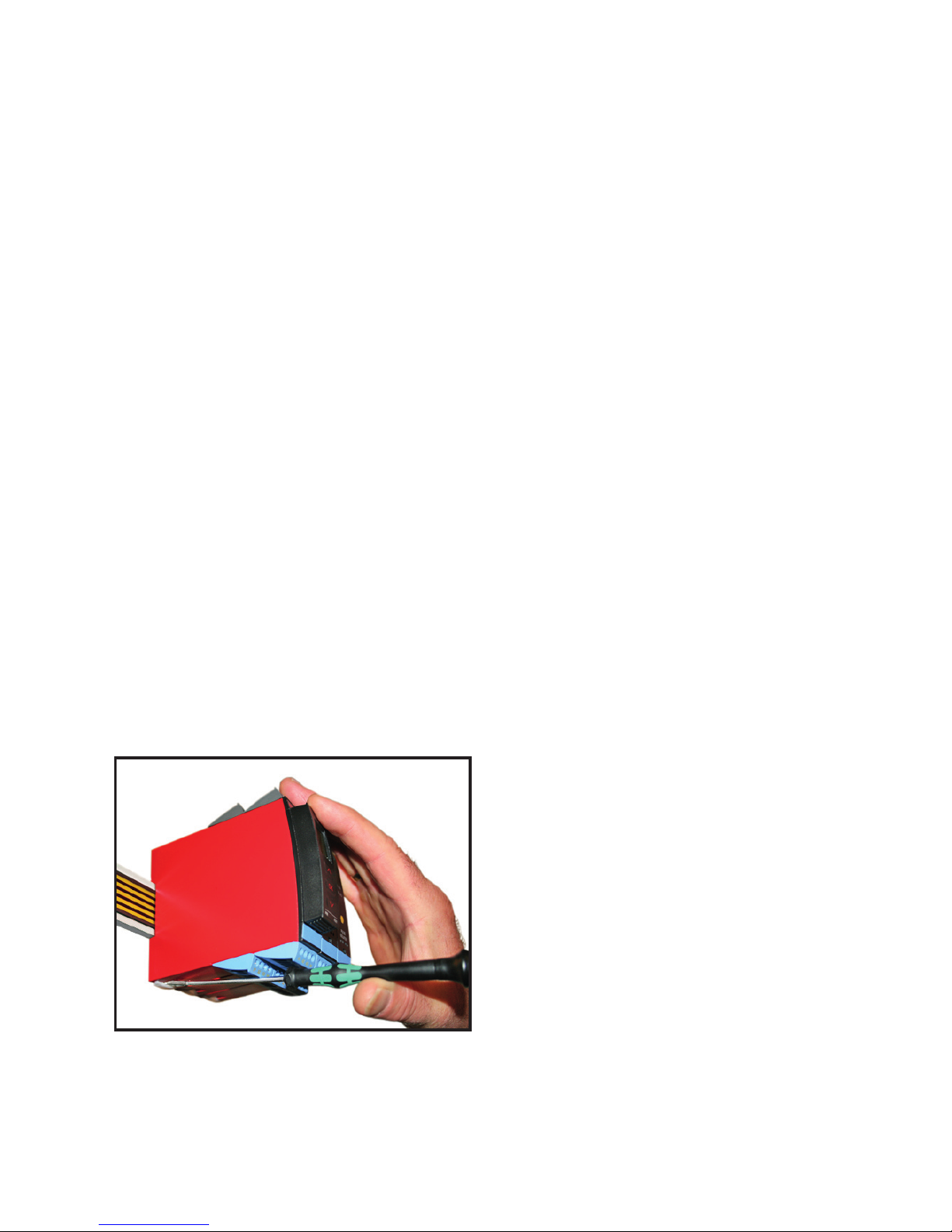
COMO DESMONTAR O SISTEMA 9000
Figura 1:
Levantando o botão de trava,
oequipamento é destacado do trilho
DIN.
Page 7

9203 - Versão do produto 9203-002 5
SOLENÓIDE / DRIVER DE ALARME
9203
• Drivers universais Ex para solenoides, alarmes acústicos e LEDs
• Auto diagnóstico extendido
• 1 ou 2 canais
• Pode ser alimentado separadamente ou instalado no trilho
de alimentação, PR 9400
• SIL 2-certificada através de avaliação completa
Recursos avançados
• Drivers Universais Ex para controle de solenoide etc, com diversos dados Ex
através de três barreiras Ex montadas.
• DuasversõesdehardwaretornampossívelescolherouBaixa(35mA)ouAlta
(60mA) corrente de saída.
• Configuraçãoemonitoramentoatravésdodisplayfrontal(PR4501).
• SeleçãodefunçãodiretaouinvertidaparacadacanalviaPR4501e
possibilidade de reduzir a corrente de saída de áreas perigosas para se adequar
à aplicação.
• Monitoramentoopcionaldacorrentedesaídaparaáreasperigosasatravésdo
PR4501.
• Alimentação opcional via trilho de tensão e/ou alimentação separada.
Aplicação
• Oequipamentopodesermontado em área segura ou em zona 2 / div. 2 e
transmitir sinais para zona 0, 1, 2 e zona 20, 21, 22 incluindo mineração M1 /
Classe I/II/III, Div. 1, Gr. A-G.
• DriverExparacontroleLiga/Desligadesolenoide,alarmesacústicoseLEDs
montados em áreas perigosas.
• O9203écontroladoporumsinalNPN/PNPousinalchaveado.
• Monitoramentodeerrosinternosviastatusindividualderelée/ousinal
eletrônico coletivo via trilho de tensão.
• O 9203 foi fabricado, desenvolvido e certificado para uso em aplicações de SIL
2 cumprindo os requerimentos do IEC 61508.
Características técnicas
• LEDs frontais verde e amarelo/vermelho indicam status de operação e defeito de
funcionamento.
• Isolação galvânica de 2,6 kVAC entre entrada, saída e alimentação.
Page 8
54
53
52
51
31
32
33
34
14
13
12
11
44
43
42
41
V
+
V
+
V
+
V
+
6 9203 - Versão do produto 9203-002
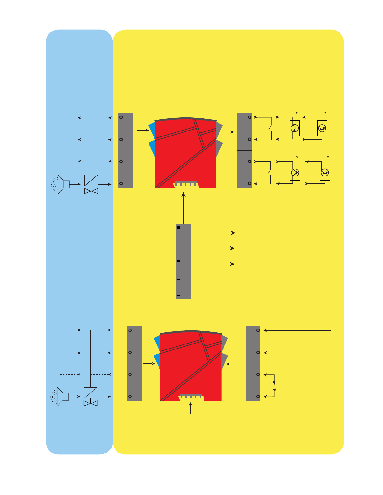
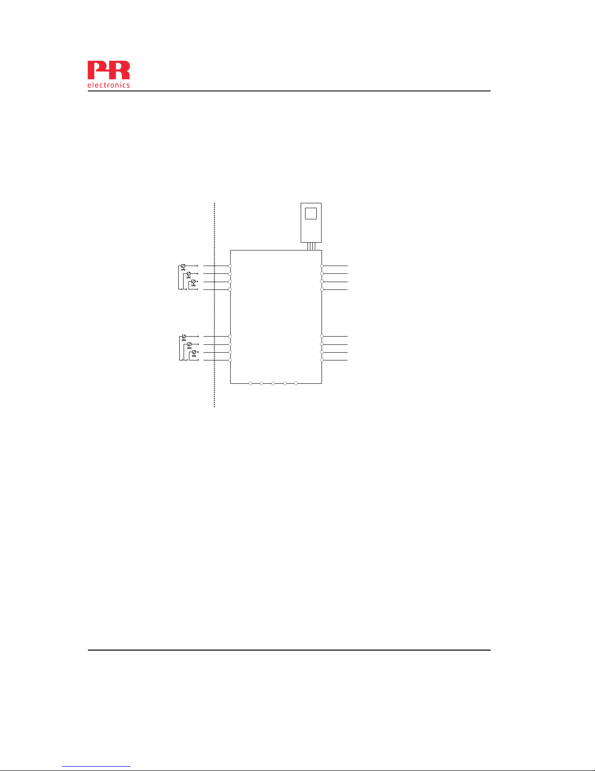
APLICAÇÕES
Trilho, +24 VDC
Trilho, Gnd.
Trilho de
tensão
Sinal do status do relé
Zona 0, 1, 2,
20, 21, 22, M1 &
Cl. I/II/III, div. 1
gr. A-G
Canal 2
SolenóideAlarme
Status do equipamento
Status do equipamento
Gnd. -
Alimentação +19,2...31,2 VDC
N.C.
Alimentação via
trilho de tensão
Sinais de entrada:
Canal 2
Canal 1
Sinais de saída:
Canal 1
SolenóideAlarme
Sem conexão
Sem conexão
Conexão de tensão:
Zona 2 / Cl. 1, div. 2, gr. A-D ou área segura
Page 9
9203 - Versão do produto 9203-002 7
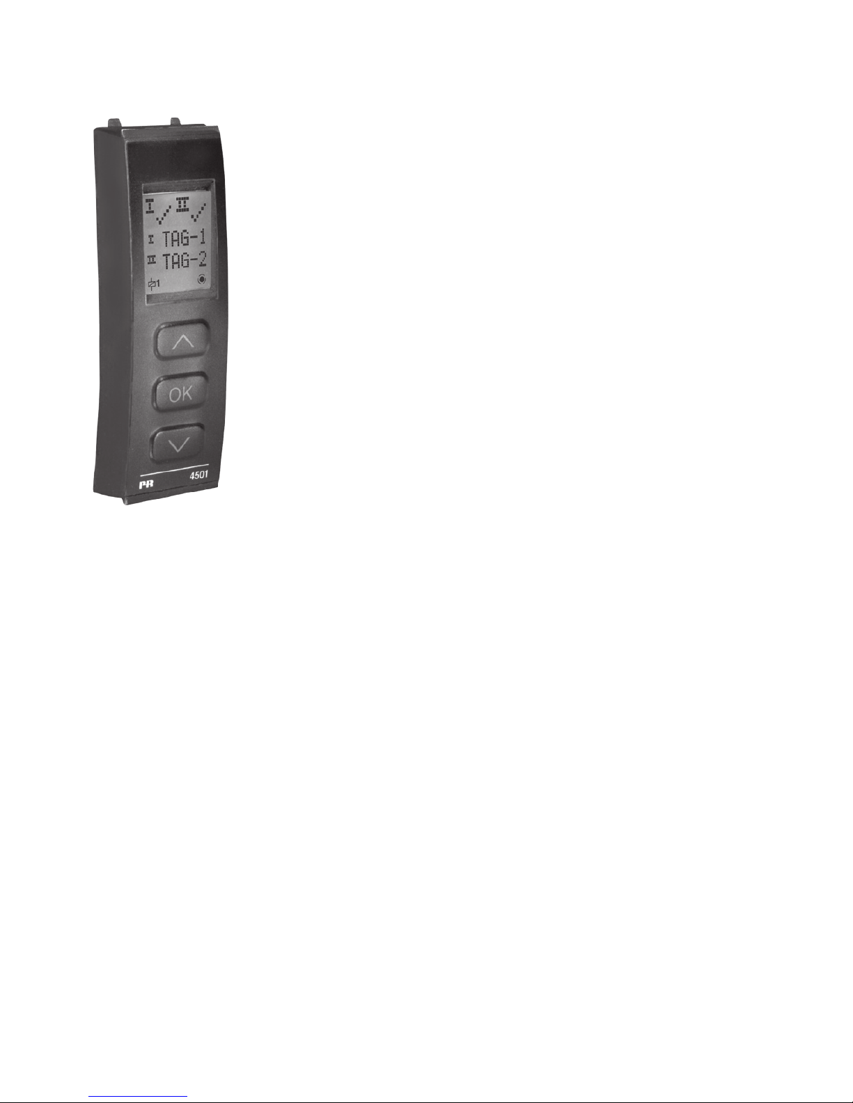
DISPLAY PR 4501 / PROGRAMAÇÃO FRONTAL
Funcionalidade
A estrutura simples do menu e de fácil compreensão e os
textos explicativos de ajuda te orientam sem dificuldades
e automaticamente através dos passos, tornando assim o
produto fácil de usar. Opções de funções e configurações
são descritos na seção “Configuração / botões de operação
e função”.
Aplicação
• Interfacedecomunicaçõesparamodificaçãodosparâmetrosoperacionaisno
9203.
• Quandomontadonoprocesso,odisplaymostravaloresdoprocessoestatusdo
equipamento.
Características técnicas
• DiplaydeLCDcom4linhas;Linha1(5.57mm)mostraostatusparacadacanal
(OK ou erro). Linha 2 (3.33 mm) mostra saída para canal 1 (ON / OFF), linha 3
(3.33 mm) mostra saída para canal 2 (ON / OFF), e a linha 4 mostra se o equipamento é SIL-bloqueado.
• Afimdeprotegeraconfiguraçãocontramudançasnãoautorizadas,oacessoao
menu pode ser bloqueado através de uma senha.
Montagem / Instalação
• Cliqueno4501emfrenteao9203.
Page 10
8 9203 - Versão do produto 9203-002
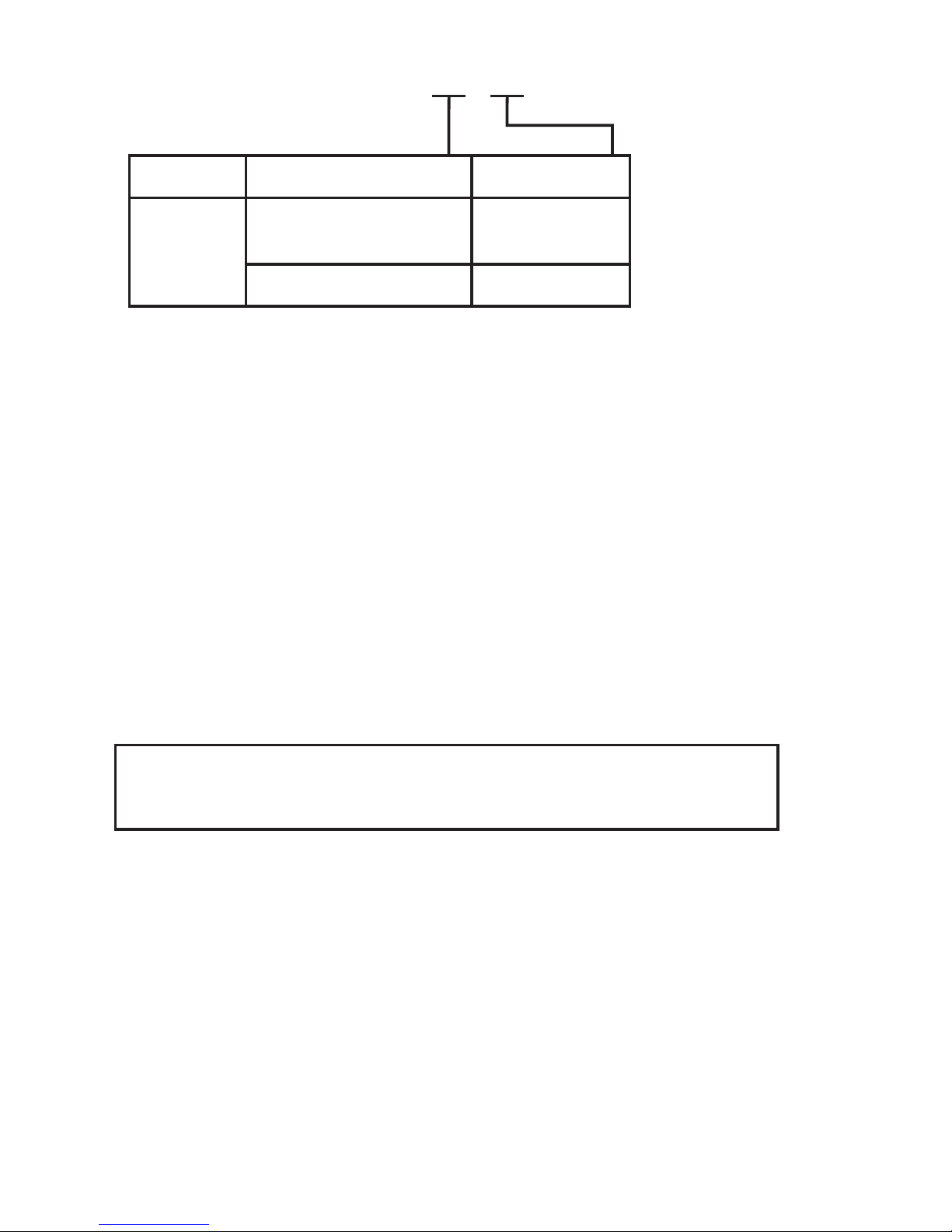
4501 = Display / programação frontal
4511 = Modbus communication enabler
9400 = Trilho de tensão
Especificações elétricas
Specificações de range .......................................... -20...+60°C
Temperatura de armazenamento ...................... -20...+85°C
Especificações comuns:
Tensão de alimentação ......................................... 19.2...31.2 VDC
Consumação máxima .............................................. ≤ 3,5 W (2 canais)
Fusível .......................................................................... 1,25 A SB / 250 VAC
Tensão de isolação, teste / operação:
Entrada / saída / alimentação ................... 2,6 kVAC / 250 VAC
Saída 1 a saída 2 ............................................ 1,5 kVAC / 150 VAC reforçado
Status do relé para alimentação............... 1,5 kVAC / 150 VAC reforçado
Interface de comunicação .................................... Programador frontal 4501
Temperatura de calibração ................................... 20...28°C
Tamanho do cabo (min....max.) ........................... 0,13...2,08 mm
2
/ AWG 26...14
fio flexível
Torque do terminal .................................................. 0,5 Nm
Umidade relativa ...................................................... < 95% RH (non-cond.)
Dimensões, sem display frontal (AxLxP) ......... 109 x 23,5 x 104 mm
Dimensões, com display frontal (AxLxP) ........ 109 x 23,5 x 116 mm
Grau de proteção ...................................................... IP20
Peso ............................................................................... 170 g / 185 g com 4501
Ordem: 9203B
Tipo Barreira Ex [Ex ia] Canais
9203B Corrente baixa ..: 1 Simples...: A
Duplo.....: B
Corrente alta....: 2 Simples...: A
Influência de imunidade EMC ......................................... < ±0,5% de span
Imunidade EMC extendida:
NAMUR NE 21, critério de explosão A ....................... < ±1% de span
Page 11

9203 - Versão do produto 9203-002 9
NPN e chave mecânica:
Nível de trig BAIXO ................................................. ≤ 2,0 VDC
Nível de trig ALTO .................................................... ≥ 4,0 VDC
Tensão externa máxima ....................................... 28 VDC
Impedância de entrada .......................................... 3,50 kΩ
PNP:
Nível de trig BAIXO ................................................. ≤ 8,0 VDC
Nível de trig ALTO .................................................... ≥ 10,0 VDC
Tensão externa máxima ....................................... 28 VDC
Impedância de entrada .......................................... 3,50 kΩ
Trig de entrada PNP especial:
Se o sinal de entrada vem de um equipamento onde a saída é conectada como
um coletor aberto com resistor pull up, um diodo precisa ser conectado em série
com o sinal de entrada. Veja os desenhos de conexões na página 14 para mais
detalhes.
Saídas:
Ondulação de saída ................................................. < 40 mV RMS
Saída relé:
Status do relé em área segura:
Tensão máxima ............................................... 125 VAC / 110 VDC
Corrente máxima ............................................ 0,5 A AC / 0,3 A DC
Tensão máxima ............................................... 62,5 VA / 32 W
Page 12

10 9203 - Versão do produto 9203-002
Aprovações:
EMC 2004/108/EC .................................................. EN 61326-1
LVD 2006/95/EC ...................................................... EN 61010-1
c UL us, Padrão para Segurança......................... UL 61010-1
GOST R
Marinha:
Det Norske Veritas, Ships & Offshore ............. Stand. f. Certific. No. 2.4
I.S. / Ex:
ATEX 94/9/EC ............................................................ KEMA 07ATEX0147 X
IECEx ............................................................................. IECEx KEM 09.0001X
c FM us ......................................................................... 3035277-C
INMETRO ..................................................................... NCC 12.1306 X
GOST Ex
Segurança Funcional:
SIL 2 Certificada & Totalmente Avaliada de acordo com IEC 615088
Page 13

9203 - Versão do produto 9203-002 11
Visualização no hardware 4501 / erro de software
Leitura de erro de hardware:
Pesquisa de erro Leitura Causa
Teste de comunicação 4501 / 9203 NO.CO Erro de conexão
Erro EEPROM - checar configuração FL.ER
Erro de configuração ou incompatibi-
lidade crc, configuração de recuperação
é carregado
Erro de hardware DE.ER Configuração de recuperação inválida
Erro de hardware FC.ER Código inválido de recuperação 4501
Erro EEPROM - checar configuração CO.ER
Configuração inválida
(CRC ou dados)
Erro de hardware CA.ER Erro de calibração de fábrica
Erro de hardware HW.ER
Setup HW -
incompatibilidade de configuração
Erro de hardware OC.ER
Erro de comunicação na saída principal
do controlador
Erro de hardware MS.ER
Alimentação principal interna
fora do limite
Erro de hardware MI.ER
Inicialização principal
auto teste falhou
Erro de hardware MC.ER
Flash principal ou ram
auto teste falhou
Page 14
11 12 13 14
11 12 13 14
V
+
11 12 13 14
V
+
11 12 13 14
V
+
R
D
31 32 33 34
+24 V
91 92 93 94 95
+24 V
41 42 43 4441 42 43 44 41 42 43 44
51 52 53 54 51 52 53 54 51 52 53 54
11 12 13 14
11 12 13 14
V
+
11 12 13 14
V
+
11 12 13 14
V
+
V
+
R
D
12 9203 - Versão do produto 9203-002
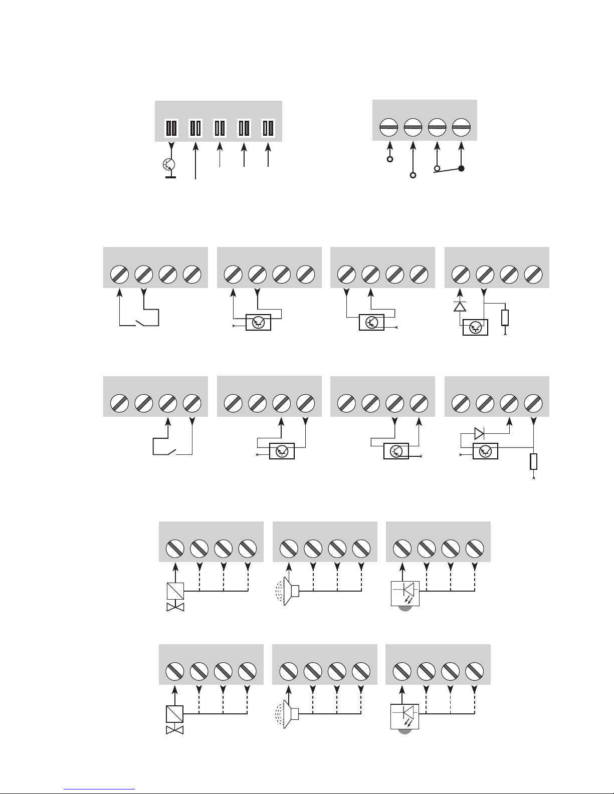
CONEXÕES
Saídas:
Alimentação e
status do relé
N.C.
Gnd.
NCNCGnd.
Erro
Conexões
do trilho de alimentação
Canal 1Canal 2
Trig de entrada
PNP especial
Entradas:
Canal 1
Canal 2
Chave Chave, PNPChave, NPN
Alarme acústico LED
Solenóide, ON / OFF Alarme acústico LED
Solenóide, ON / OFF
NC = Sem conexão
Trig de entrada
PNP especialChave Chave, PNPChave, NPN
Page 15
92039203
31
12
11
91
92 93 94 95
323433
44
43
41
42
14
13
54
53
51
52
NC*NC*
+24V
CPU
FLASH
R Ex3
R Ex2
R Ex1
R Ex3
R Ex2
R Ex1
V
+
NPN
V
+
PNP
D
V
+
R
V
+
NPN
V
+
PNP
D
V
+
R
1
ON
OFF
9203 - Versão do produto 9203-002 13
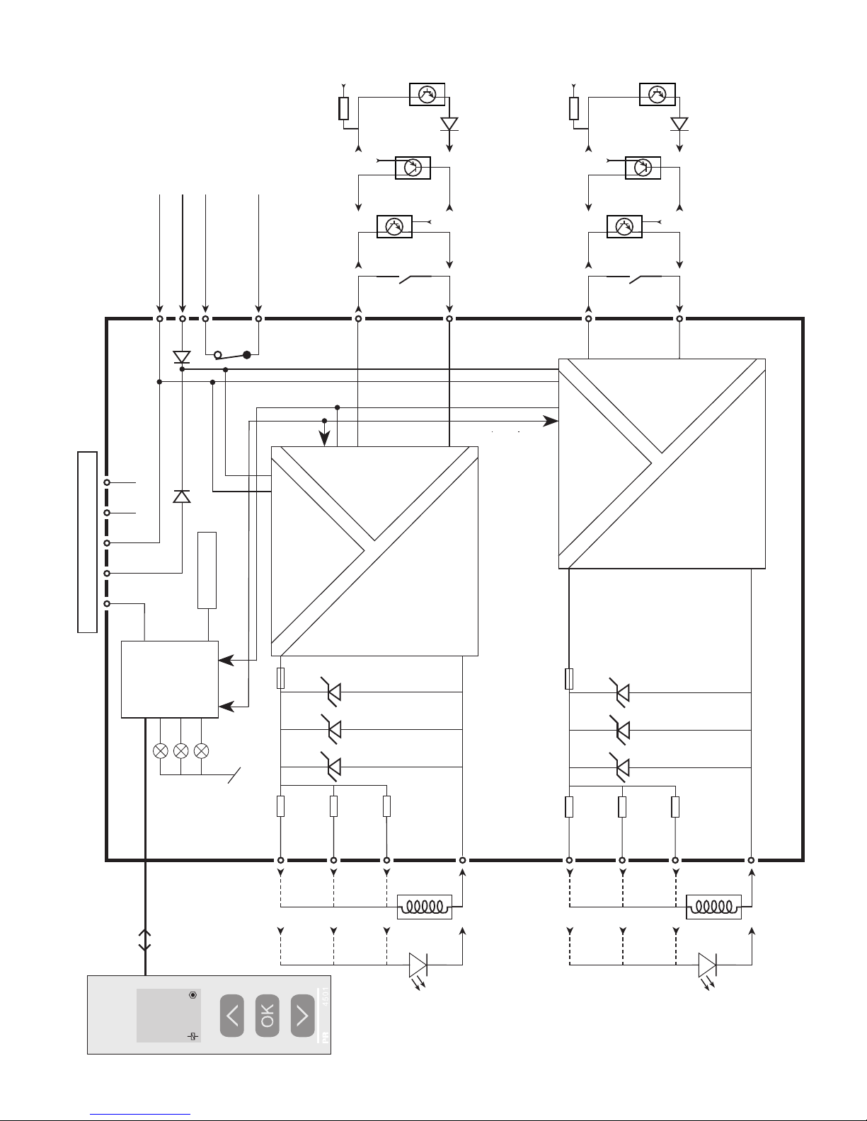
DIAGRAMA DE BLOCO
Conexões de trilho de tensão
Status de relé N.C.
Status de relé N.C.
Gnd. -
Alimentação +24 VDC
Entrada +
Entrada, gnd.
Trig de entrada
PNP especial
Canal 1
Canal 2
Chave
Entrada +
Entrada, gnd.
Chave
Saída +
Saída, gnd.
Saída +
Saída, gnd.
Fusível
Fusível
Trig de entrada
PNP especial
Status do equipamento,
Verde
Status canal 1, Amarelo/
Vermelho
Status canal 2, Amarelo/
Vermelho
* NC = no connection
(sem conexão)
Page 16
14 9203 - Versão do produto 9203-002
Indicações de erro de sinal sem display frontal
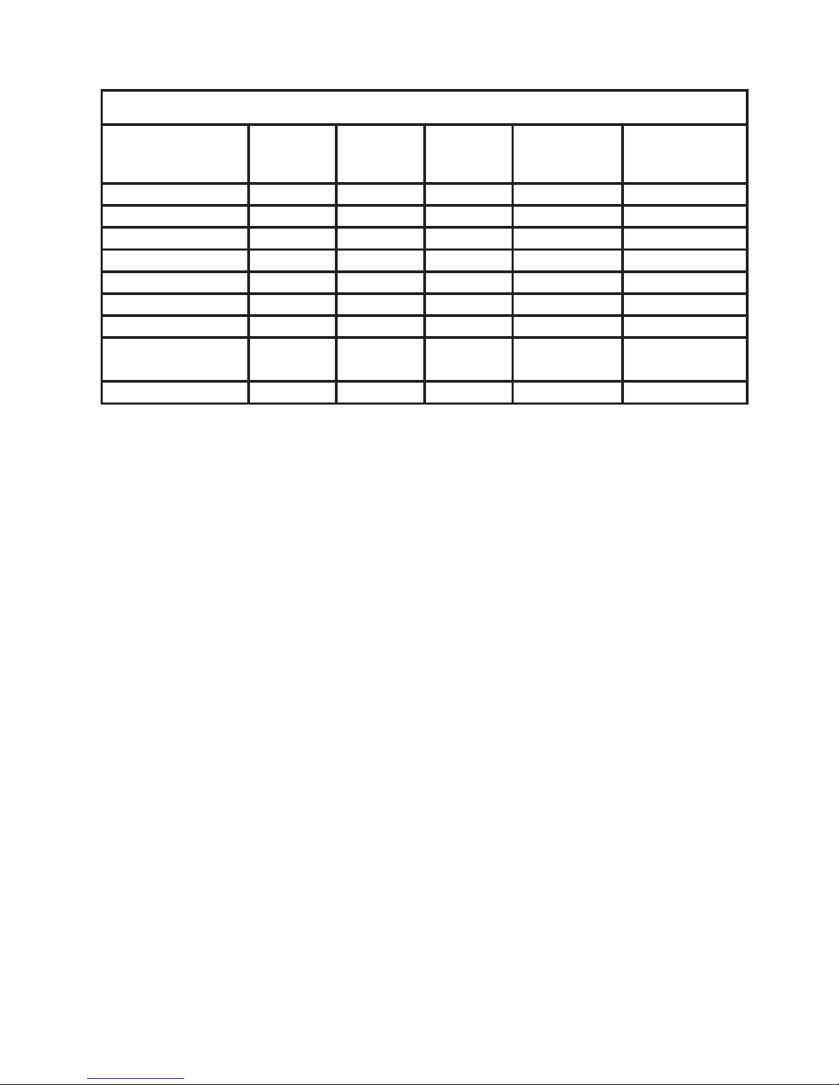
CONFIGURAÇÃO /
OPERANDO OS BOTÕES DE FUNÇÕES
Documentação de diagrama de encaminhamento.
No geral
Quando configurar o 9203, você será guiado através de todos os parâmetros e
você pode escolher os ajustes para colocar na aplicação. Para cara menu há
textos de ajuda que são automaticamente mostrados na linha 3 do display.
Configuração pode ser realizada através de 3 botões de função:
1 irá aumentar o valor numérico ou escolher o próximo parâmetro
2irá diminuir o valor numérico ou escolher o parâmetro anterior
3irá aceitar o valor escolhido e seguir para o próximo parâmetro
Quando a configuração está completa, o display irá retornar para o estado padrão
1.0.
Pressionando e segurando
3 irá retornar para o menu anterior ou retornar para o
estado padrão (1.0) sem salvar os valores ou parâmetros alterados.
Se nenhum botão é pressionado por 1 minuto, o display irá retornar para o estado
padrão (1.0) sem salvar os valores ou parâmetros alterados.
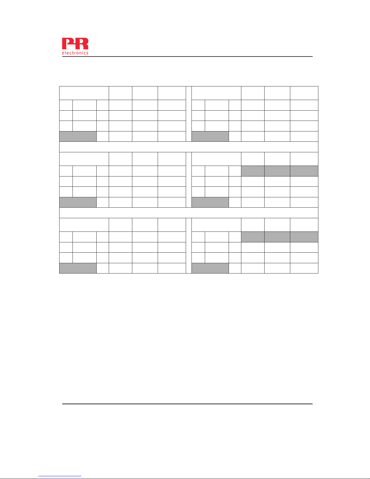
Lista de LED e indicação de erro de sinal
Estado LED Verde
Ca. 1:
Amarelo /
vermelho
Ca. 2:
Amarelo /
vermelho
Status do relé,
N.C.
Trilho de tensão
status de sinal
Módulo OK Piscando Energizado OFF
Sem alimentação OFF OFF OFF Desenergizado ON
Módulo com defeito OFF Vermelho Vermelho Desenergizado ON
Canal 1, saída ON Piscando Amarelo Energizado OFF
Canal 1, saída OFF Piscando OFF Energizado OFF
Canal 2, saída ON Piscando Vermelho Energizado OFF
Canal 2, saída OFF Piscando OFF Energizado OFF
Page 17

9203 - Versão do produto 9203-002 15
Mais explicações
Senha de proteção: O acesso à programação pode ser bloqueado atribuindo
uma senha. A senha é salva no equipamento a fim de garantir um alto nível de
proteção contra modificações não autorizadas na configuração. A senha padrão
2008 permite o acesso a todos os menus de configuração.
Informação de erro de equipamento ou sinal via display frontal
4501
O display frontal pode ser configurado para mostrar status de saída, corrente
de saída ou número de etiqueta para ambos os canais. No caso de erro de
hardware, um texto de ajuda explicando o erro será mostrado.
Funções avançadas
A unidade dá acesso a um número de funções avançadas que podem ser
alcançadas respondendo “Yes” no parâmetro “adv.set”.
Display setup: Aqui você pode ajustar o contrate de brilho e luz de fundo.
Configuração dos números de TAG com 5 caracteres alfanuméricos. Seleção de
leitura funcional na linha 2 e 3 do display – escolha entre leitura de status de
saída, corrente de saída ou número de tag. Ao selecionar ”ALT” a leitura alterna
entre as opções de exibição.
Password: Aqui você pode escolher uma senha entre 0000 e 9999 a fim de
proteger o equipamento contra modificações da configuração não autorizadas.
O equipamento é entregado sem uma senha padrão.
Language: No menu “LANG” você pode escolher entre 7 versões de linguagens
diferentes de textos de ajuda que irão aparecer no menu. Você pode escolher
entre UK, DE, FR, IT, ES, SE e DK.
Nível de Integridade de Segurança (SIL): Veja o manual de segurança para
detalhes.
Page 18
Power up
0000
PASSW.
Txt 1
ON
OFF
3
3
NO
ADV.SET
Txt 2
0000
9999
1 2
NO
YES
1 2
3
DIR
CH1.FUN
Txt 7
DIR
INV
1 2
3
YES
ADV.SET
Txt 2
3
DIR
CH2.FUN
Txt 7
1 2
3
DIR
INV
1.1
1.0
16 9203 - Versão do produto 9203-002
Para status padrão 1.0
Diretamente de [EN.SIL]
se SIL-lock está habilitado
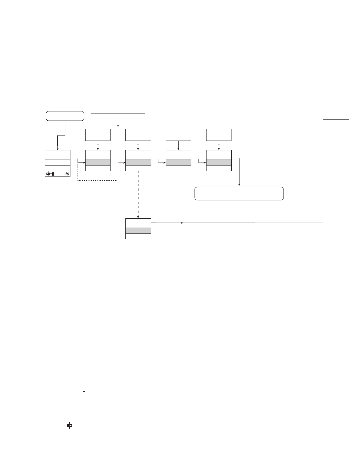
DIAGRAMA DE ENCAMINHAMENTO
Se nenhum botão é acionado por 1 minuto, o display irá retornar para o status
padrão 1.0 sem salvar as mudanças de configuração.
1 Aumenta o valor / escolhe próximo parâmetro
2 Diminui o valor / escolhe o parâmetro anterior
3 aceita o valor escolhido e procede para o próximo menu
Segurar o 3 Volta para o menu anterior / retorna para o menu 1.0 sem salvar
1.0 = Status padrão
Linha 1 mostra status para canal 1
e canal 2.
Linha 2 mostra status de saída para
canal 1, corrente de saída ou número de tag.
Linha 3 mostra status de saída para
canall 2, corrente de saída ou número de tag.
Linha 4 indica se o equipamento
está bloqueado por SIL.
1.1 = apenas se houver senha de proteção.
1.2 = Se a senha foi definida.
Símbolos da linha 1:
= OK. Piscando = erro.
Linha 2 e 3 símbolos:
ON = canal 1 ON
OFF = canal 2 OFF.
Símbolos da linha 4:
Dot estática = bloqueado por SIL.
Dot piscando = sem bloqueio SIL.
= saída está ativa.
Texto vermelho
significa parâmetros
de segurança na
configuração SIL. Veja
o manual de segurança
para detalhes
Page 19
DISP,
PASS,
LANG,
SIL
1 2
DISP
SETUP
Txt 6
3
3
CONTRA
Txt 9
3
9
0
1 2
9
LIGHT
Txt 10
3
9
0
1 2
TAG1
VALVE 5
Txt 11
3
9
A
1 2
TAG2
VALVE 6
Txt 11
3
9
A
1 2
LANG
SETUP
Txt 06
3
UK
LANGUA
Txt 17
DE, DK, ES, FR,
IT, SE, UK
1 2
PASS
SETUP
Txt 06
3 3
YES
EN.PASS
Txt 15
3
YES
NO
1 2
NO
0000
NEW.PAS
Txt 16
3
9999
0000
1 2
SIL
SETUP
Txt 06
3
YES
EN.SIL
Txt 14
YES
NO
1 2
NO
3
2008
NEW.PAS
Txt 16
0000
9999
1 2
3
LOCK
CONFIG
Txt 13
SIL.OK
. . . . . . . . . . . . . .
3 3 3 3
3
3
LOAD
DISP
Txt 12
ALT
LOAD
TAG
D.OUT
1 2
3
3
LOCK
OPEN
1 2
1.2
9203 - Versão do produto 9203-002 17
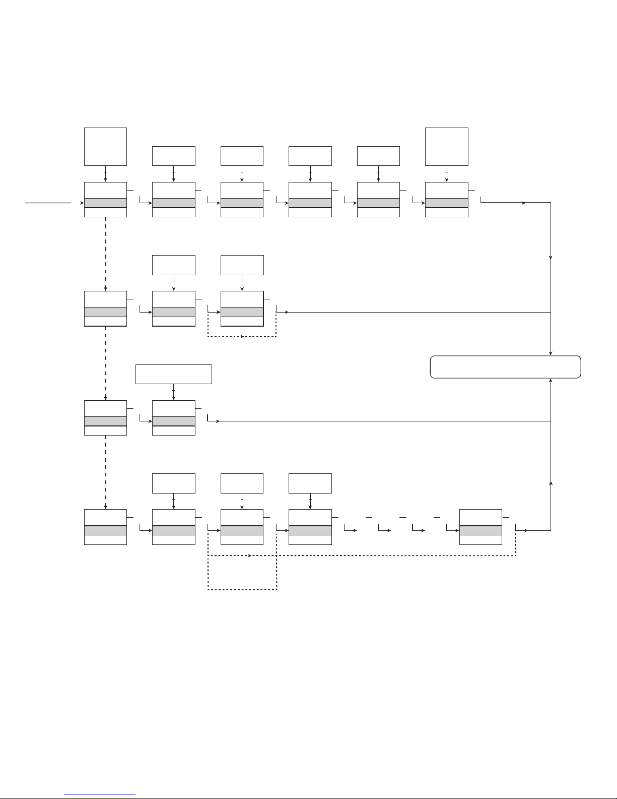
DIAGRAMA DE ENCAMINHAMENTO, CONFIGURAÇÕES
AVANÇADAS (ADV.SET)
Para status padrão 1.0
Verificar configuração SIL
Page 20

18 9203 - Versão do produto 9203-002
TEXTOS DE AJUDA NA LINHA 3 DO DISPLAY
[01]
[02]
[06]
[07]
[09]
[10]
[11]
[12]
[13]
[14]
[15]
[16]
[17]
[20]
[21]
[22]
Definir a senha correta
Entrar nas configurações avançadas?
Entrar nas configurações de linguagem
Entrar nas configurações de senha
Entrar nas configurações de display
Entrar nas configurações de SIL
Selecionar função de canal direto
Selecionar função de canal invertido
Ajustar contraste LCD
Ajustar luz de fundo do LCD
Escrever 5 caracteres de tag do canal
Mostra status de saída no display
Mostra carga de saída no display
Mostra tag no display
Informação alternada mostrada no display
Configuração de status SIL (Aberto / Bloqueado)
Habilitar configuração de bloqueio SIL
Habilitar senha de proteção?
Configurar nova senha
Selecionar linguagem
Sem comunicação - checar as conexões
Erro EEPROM - checar configuração
Erro de hardware
Page 21

9203 - Versão do produto 9203-002 19
APÊNDICE
DESENHO DE INSTALAÇÃO IECEX
DESENHO DE INSTALAÇÃO ATEX
DESENHO DE INSTALAÇÃO FM
DESENHO DE INSTALAÇÃO INMETRO
SAFETY MANUAL
Page 22
9203QI01
Revision date:
2011-11-20
Version Revision
V5 R0
Prepared by:
PB
Page:
1/3
IECEx Installation drawing
For safe installation of 9203B the following must be observed. The module shall only be Installed by
qualified personnel who are familiar with the national and international laws, directives and
standards that apply to this area.
Year of manufacture can be taken from the first two digits in the serial number.
For Installation in Zone 2 / Division 2 the following must be observed.
The 4501 programming module is to be used solely with PRelectronics modules. It is important
that the module is undamaged and has not been altered or modified in any way. Only 4501
modules free of dust and moisture shall be installed.
IECEx Certificate: IECEx KEM 09.0001X
Marking
Standards IEC60079-15:2005, IEC60079-11:2011, IEC60079-0:2011
IEC60079-26:2006
Installation notes.
Install in pollution degree 2, overvoltage category II as defined in IEC60664-1
Do not separate connectors when energized and an explosive gas mixture is present.
Do not mount or remove modules from the Power Rail when an explosive gas mixture is present.
Disconnect power before servicing.
The wiring of unused terminals is not allowed.
In type of protection [Ex ia Da] the parameters for intrinsic safety for gas group IIB are applicable.
For installation in Zone 2, the module shall be installed in an enclosure in type of protection Ex n
or Ex e, providing a degree of protection of at least IP54. Cable entry devices and blanking
elements shall fulfill the same requirements.
For installation on Power Rail in Zone 2, only Power Rail type 9400 supplied by Power Control Unit
type 9410 (Type Examination Certificate KEMA 07ATEX0152 X) is allowed.
[Ex ia Ga] IIC/IIB/IIA
Ex nA nC IIC T4 Gc
[Ex ia Da] IIIC
[Ex ia Ma] I
20 9203 - Versão do produto 9203-002
Page 23
9203QI01
Revision date:
2011-11-20
Version Revision
V5 R0
Prepared by:
PB
Page:
2/3
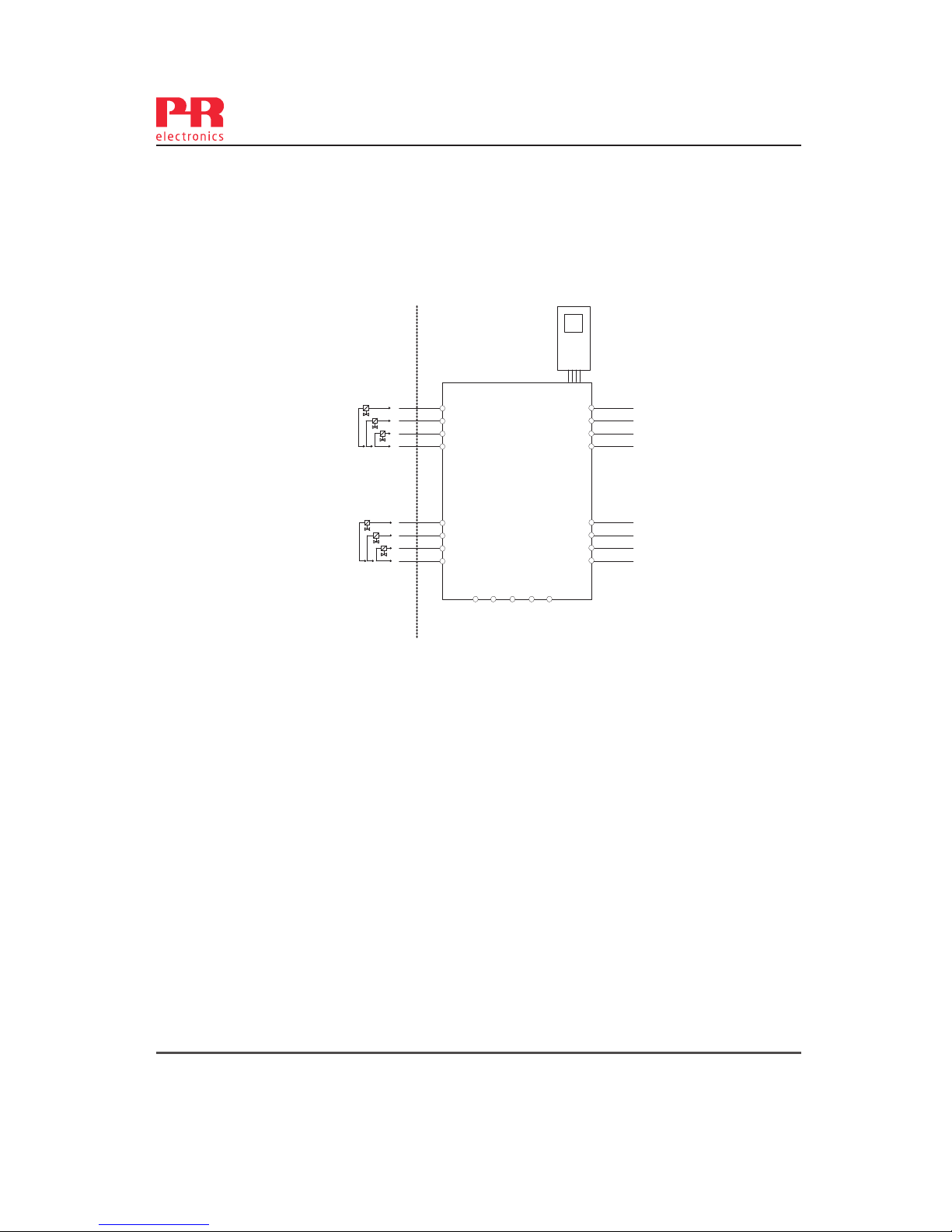
Hazardous area Non Hazardous area
Zone 0, 1, 2, 20, 21, 22 or Zone 2
Terminal (31,32) Terminal (11,12 and 13,14)
Supply: Input:
Voltage 19.2 – 31.2 VDC Voltage max 28VDC
Power max. 3.5 W Trig: NPN Low < 2 V, High > 4 V
Trig: PNP Low < 8 V, High > 10 V
Terminal (33,34)
Status Relay: Non Hazardous location Zone 2 installation
Voltage max. 125 VAC / 110 VDC 32 VAC / 32 VDC
Power max. 62.5 VA / 32 W 16 VA / 32 W
Current max. 0.5 AAC / 0.3 ADC 0.5 AAC / 1 ADC
Supply / Input
(terminal 11,12,13,14)
(terminal 31,32,33,34)
(terminal 91,92,93,94,95)
Um: 253V, max. 400Hz
-20 ≤ Ta ≤ 60ºC
44
43
42
41
54
53
52
51
34
33
32
31
14
13
12
11
9203
4501
Power
Rail
91 92 93 94 95
9203 - Versão do produto 9203-002 21
Page 24
9203QI01
Revision date:
2011-11-20
Version Revision
V5 R0
Prepared by:
PB
Page:
3/3
9203B1A, 9203B1B
Terminal 41-42/51-52
Co Lo Lo/Ro
9203B2A
Terminal 41-42
Co Lo Lo/Ro
Uo
28V IIC 80nF 4.2mH 54µH/Ω
Uo
28V IIC 80nF 2.69mH 44µH/Ω
Io
93 mA IIB 640nF 16.8mH 218µH/Ω
Io
115mA IIB 640nF 10.8mH 176µH/Ω
Po
0.65W IIA 2.1µF 32.6mH 436µH/Ω
Po
0.81W IIA 2.1µF 20.8mH 353µH/Ω
I 3.76µF 32.6mH 436µH/Ω
I 3.76µF 20.8mH 353µH/Ω
9203B1A, 9203B1B
Terminal 41-43/51-53
Co Lo Lo/Ro
9203B2A
Terminal 41-43
Co Lo Lo/Ro
Uo
28V IIC 80nF 3.5mH 50µH/Ω
Uo
28V IIC
Io
100mA IIB 640nF 14.2mH 201µH/Ω
Io
125mA IIB 640nF 9.1mH 163µH/Ω
Po
0.70W IIA 2.1µF 27.6mH 402µH/Ω
Po
0.88W IIA 2.1µF 17.6mH 327µH/Ω
I 3.76µF 27.6mH 402µH/Ω
I 3.76µF 17.6mH 327µH/Ω
9203B1A,9203B1B
Terminal 41-44/51-54
Co Lo Lo/Ro
9203B2A
Terminal 41-44
Co Lo Lo/Ro
Uo
28V IIC 80nF 2.9mH 46µH/Ω
Uo
28V IIC
Io
110mA IIB 640nF 11.8mH 184µH/Ω
Io
135mA IIB 640nF 7.8mH 150µH/Ω
Po
0.77W IIA 2.1µF 22.8mH 369µH/Ω
Po
0.95W IIA 2.1µF 15.1mH 301µH/Ω
I 3.76µF 22.8mH 369µH/Ω
I 3.76µF 15.1mH 301µH/Ω
22 9203 - Versão do produto 9203-002
Page 25
9203 - Versão do produto 9203-002 23
9203QA01
Revision date:
2011-11-20
Version Revision
V5 R0
Prepared by:
PB
Page:
1/3
ATEX Installation drawing
For safe installation of 9203B the following must be observed. The module shall only be installed by
qualified personnel who are familiar with the national and international laws, directives and
standards that apply to this area.
Year of manufacture can be taken from the first two digits in the serial number.
For Installation in Zone 2 / Division 2 the following must be observed.
The 4501 programming module is to be used solely with PR electronics modules. It is important
that the module is undamaged and has not been altered or modified in any way. Only 4501
modules free of dust and moisture shall be installed.
ATEX Certificate KEMA 07ATEX 0147 X
Marking
Standards EN 60079-0 : 2009, EN 60079-11 : 2007, EN 60079-15 : 2005
EN 60079-26 : 2007, EN 61241-11 : 2006
Terminal (31,32) Terminal (11,12 and 13,14)
Supply: Input:
Voltage 19.2 – 31.2 VDC Voltage max 28VDC
Power max. 3.5 W Trig: NPN Low < 2 V, High > 4 V
Trig: PNP Low < 8 V, High > 10 V
Terminal (33,34)
Status Relay: Non Hazardous location Zone 2 installation
Voltage max. 125 VAC / 110 VDC 32 VAC / 32 VDC
Power max. 62.5 VA / 32 W 16 VA / 32 W
Current max. 0.5 AAC / 0.3 ADC 0.5 AAC / 1 ADC
Installation notes.
Install in pollution degree 2, overvoltage category II as defined in EN60664-1
Do not separate connectors when energized and an explosive gas mixture is present.
Do not mount or remove modules from the Power Rail when an explosive gas mixture is present.
Disconnect power before servicing.
The wiring of unused terminals is not allowed.
In type of protection [Ex ia Da] the parameters for intrinsic safety for gas group IIB are applicable.
For installation in Zone 2, the module shall be installed in an enclosure in type of protection Ex n
or Ex e, providing a degree of protection of at least IP54. Cable entry devices and blanking
elements shall fulfill the same requirements.
For installation on Power Rail in Zone 2, only Power Rail type 9400 supplied by Power Control Unit
type 9410 (Type Examination Certificate KEMA 07ATEX0152 X) is allowed.
II (1) G [Ex ia Ga] IIC/IIB/IIA
II 3G Ex nA nC IIC T4 Gc
I (1) D [Ex ia Da] IIIC
I (M1) [Ex ia Ma] I
Page 26
24 9203 - Versão do produto 9203-002
9203QA01
Revision date:
2011-11-20
Version Revision
V5 R0
Prepared by:
PB
Page:
2/3
Non Hazardous Area
or Z
one 2
Hazardous area
Zone 0,1,2, 20, 21, 22
Supply / Input
(terminal 11,12,13,14)
(terminal 31,32,33,34)
(terminal 91,92,93,94,95)
Um: 253 V, max. 400 Hz
-20 ≤ Ta ≤ 60ºC
44
43
42
41
54
53
52
51
34
33
32
31
14
13
12
11
9203
4501
Power
Rail
91 92 93 94 95
Page 27
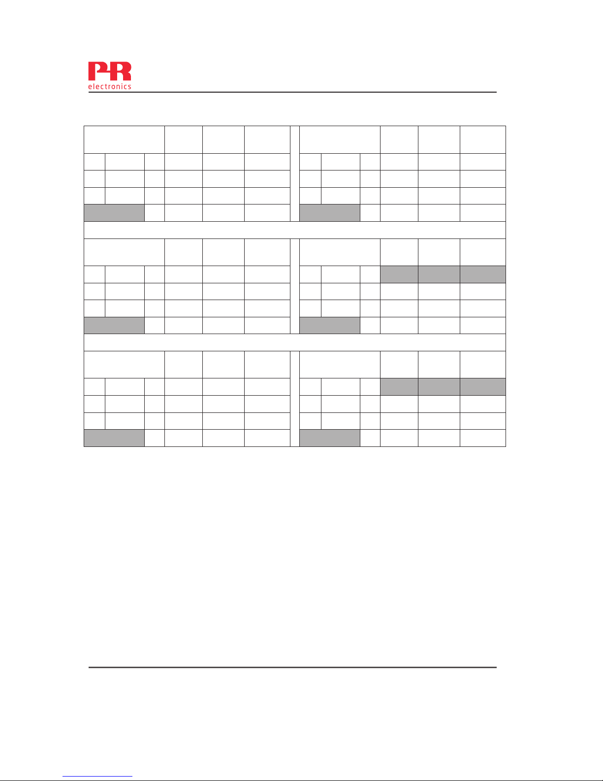
9203 - Versão do produto 9203-002 25
9203QA01
Revision date:
2011-11-20
Version Revision
V5 R0
Prepared by:
PB
Page:
3/3
9203B1A, 9203B1B
Terminal 41-42/51-52
Co Lo Lo/Ro
9203B2A
Terminal 41-42
Co Lo Lo/Ro
Uo
28V IIC 80nF 4.2mH 54µH/Ω
Uo
28V IIC 80nF 2.69mH 44µH/Ω
Io
93 mA IIB 640nF 16.8mH 218µH/Ω
Io
115mA IIB 640nF 10.8mH 176µH/Ω
Po
0.65W IIA 2.1µF 32.6mH 436µH/Ω
Po
0.81W IIA 2.1µF 20.8mH 353µH/Ω
I 3.76µF 32.6mH 436µH/Ω
I 3.76µF 20.8mH 353µH/Ω
9203B1A, 9203B1B
Terminal 41-43/51-53
Co Lo Lo/Ro
9203B2A
Terminal 41-43
Co Lo Lo/Ro
Uo
28V IIC 80nF 3.5mH 50µH/Ω
Uo
28V IIC
Io
100mA IIB 640nF 14.2mH 201µH/Ω
Io
125mA IIB 640nF 9.1mH 163µH/Ω
Po
0.70W IIA 2.1µF 27.6mH 402µH/Ω
Po
0.88W IIA 2.1µF 17.6mH 327µH/Ω
I 3.76µF 27.6mH 402µH/Ω
I 3.76µF 17.6mH 327µH/Ω
9203B1A, 9203B1B
Terminal 41-44/51-54
Co Lo Lo/Ro
9203B2A
Terminal 41-44
Co Lo Lo/Ro
Uo
28V IIC 80nF 2.9mH 46µH/Ω
Uo
28V IIC
Io
110mA IIB 640nF 11.8mH 184µH/Ω
Io
135mA IIB 640nF 7.8mH 150µH/Ω
Po
0.77W IIA 2.1µF 22.8mH 369µH/Ω
Po
0.95W IIA 2.1µF 15.1mH 301µH/Ω
I 3.76µF 22.8mH 369µH/Ω
I 3.76µF 15.1mH 301µH/Ω
Page 28
9203QF01
LERBAKKEN 10, 8410 RØNDE DENMARK
Revision date:
2011-11-20
Version Revision
V5 R0
Prepared by:
PB
Page:
1/2
FM Installation drawing
For safe installation of 9203B the following must be observed. The module shall only be
installed by qualified personnel who are familiar with the national and international laws,
directives and standards that apply to this area.
Year of manufacture can be taken from the first two digits in the serial number.
For Installation in Zone 2 / Division 2 the following must be observed.
The 4501 programming module is to be used solely with PRelectronics modules. It is
important that the module is undamaged and has not been altered or modified in any way.
Only 4501 modules free of dust and moisture shall be installed.
c-FM-us Certificate 3035277
Non Hazardous Area or
Class I, Division 2, Group A,B,C,D T4
or Class I, Zone 2 Group IIC T4
-20 ≤ Ta ≤ 60ºC
44
43
42
41
54
53
52
51
34
33
32
31
14
13
12
11
9203
4501
Power
Rail
91 92 93 94 95
Supply / Input
(terminal 11,12,13,14)
(terminal 31,32,33,34)
(terminal 91,92,93,94,95)
U
m
: 253V, max. 400Hz
Hazardous area
Class I/II/III, Division 1, Group A,B,C,D,E,F,G
or Class I, Zone 0/1 Group IIC, [AEx ia] IIC or
or Class I, Zone 0/1 Group IIC, [Ex ia] IIC
Simple Apparatus or
Intrinsically safe apparatus
with entity parameters:
Vmax (Ui) ≥ Vt (Uo)
Imax (Ii) ≥ It (Io)
Pi ≥ Pt(Po)
Ca(Co) ≥ C
cable + Ci
La(Lo) ≥ L
cable + Li
26 9203 - Versão do produto 9203-002
Page 29
9203QF01
LERBAKKEN 10, 8410 RØNDE DENMARK
Revision date:
2011-11-20
Version Revision
V5 R0
Prepared by:
PB
Page:
2/2
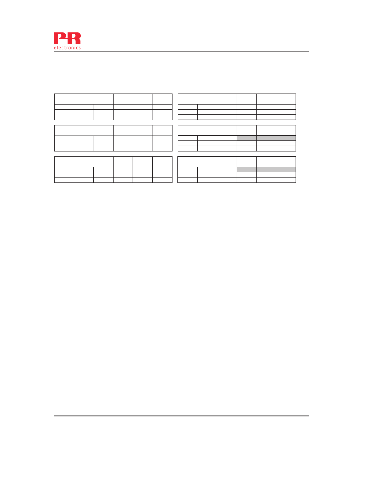
Uo/Voc 28 V
IIC or A,B
80 nF 4.2 mH 54 μH/Ω Uo/Voc 28 V
IIC or A,B
80 nF 2.69 mH 44 μH/Ω
Io/Is c 93 mA
IIB or C ,E,F
640 nF 16.8 mH 218 μH/Ω Io/Isc 115 mA
IIB or C ,E,F
640 nF 10.8 mH 176 μH/Ω
Po 0.65 W
IIA or D,G
2.1 μF 32.6 mH 436 μH/Ω Po 0.81 W
IIA or D,G
2.1 μF 20.8 mH 353 μH/Ω
Uo/Voc 28 V
IIC or A,B
80 nF 3.5 mH 50 μH/Ω Uo/Voc 28 V
IIC or A,B
Io/Isc 100 mA
IIB or C ,E,F
640 nF 14.2 mH 201 μH/Ω Io/Isc 125 mA
IIB or C ,E,F
640 nF 9.1 mH 163 μH/Ω
Po 0.70 W
IIA or D,G
2.1 μF 27.6 mH 402 μH/Ω Po 0.88 W
IIA or D,G
2.1 μF 17.6 mH 327 μH/Ω
Uo/Voc 28 V
IIC or A,B
80 nF 2.9 mH 46 μH/Ω Uo/Voc 28 V
IIC or A,B
Io/Isc 110 mA
IIB or C ,E,F
640 nF 11.8 mH 184 μH/Ω Io/Isc 135 mA
IIB or C ,E,F
640 nF 7.8 mH 150 μH/Ω
Po 0.77 W
IIA or D,G
2.1 μF 22.8 mH 369 μH/Ω Po 0.95 W
IIA or D,G
2.1 μF 15.1 mH 301 μH/Ω
Module 9203B2A
Terminal 41-44
Co/Ca Lo/La
Lo/Ro or
La/Ra
Module 9203B1A & 9203B1B
Terminal 41-44 / 51-54
Co/Ca Lo/La
Lo/Ro or
La/Ra
Module 9203B2A
Terminal 41-43
Co/Ca Lo/La
Lo/Ro or
La/Ra
Module 9203B1A & 9203B1B
Terminal 41-43 / 51-53
Co/Ca Lo/La
Lo/Ro or
La/Ra
Module 9203B2A
Terminal 41-42
Co/Ca Lo/La
Lo/Ro or
La/Ra
Module 9203B1A & 9203B1B
Terminal 41-42 / 51-52
Co/Ca Lo/La
Lo/Ro or
La/Ra
Terminal (31,32) Terminal (11,12 and 13,14)
Supply: Input:
Voltage 19.2 – 31.2 VDC Voltage max 28VDC
Power max. 3.5 W Trig: NPN Low < 2V, High > 4V
Trig: PNP Low < 8V, High > 10V
Terminal (33,34)
Status Relay: Non Hazardous location: Division 2 or Zone 2 installation:
Voltage max. 125 VAC / 110 VDC 32 VAC / 32VDC
Power max. 62.5 VA / 32 W 16 VA / 32 W
Current max. 0.5 AAC / 0.3 ADC 0.5 AAC / 1 ADC
Installation notes:
The installation and wiring shall be in accordance with the Canadian Electrical Code for Canada and
National Electrical Code NFPA 70, Article 500 or 505 for installation in USA.
The module must be supplied from a Power Supply having double or reinforced insulation.
The use of stranded wires is not permitted for mains wiring except when wires are fitted with cable
ends.
For installation on the 9400 Power Rail the power must be supplied from Power Control Module Unit
9410.
Install in pollution degree 2, overvoltage category II.
The module must be installed in an enclosure suitable for the environment for which it is used.
For installation in Zone 2 or Division 2, the module must be installed in a suitable outer enclosure
according to the regulations in the CEC for Canada or NEC for USA.
The module is galvanically isolated and does not require grounding.
Use 60 / 75 ºC copper conductors with wire size AWG: (26-14).
The maximum internal Power dissipation for adjacent modules is assumed to be max. 2W each.
Warning: Substitution of components may impair intrinsic safety and / or suitability for Div. 2 / Zone 2.
Warning: To prevent ignition of explosive atmospheres, disconnect power before servicing and do not
separate connectors when energized and an explosive gas mixture is present.
Warning: Do not mount or remove modules from the Power Rail when an explosive gas mixture is
present.
9203 - Versão do produto 9203-002 27
Page 30
9203QB01
LERBAKKEN 10, 8410 RØNDE DENMARK
Revision date:
2013-05-31
Version Revision
V5 R0
Prepared by:
PB
Page:
1/3
INMETRO Desenhos para Instalação
Para instalação segura do 9203B o manual seguinte deve ser observado. O módulo deve ser
instalado somente por profissionais qualificados que estão familiarizados com as leis nacionais e
internacionais, diretrizes e normas que se aplicam a esta área.
Ano de fabricação pode ser obtido a partir dos dois primeiros dígitos do número de série.
4501
Para a instalação na Zona 2 o seguinte deve ser observado. O módulo de programação de 4501,
deve ser utilizado apenas com os módulos PRelectronics. É importante que o módulo esteja
intacto e não tenha sido alterado ou modificado de qualquer maneira. Apenas os módulos 4501
livres de poeira e umidade devem ser instalados.
INMETRO Certificado ………… NCC 12.1306X
Marcas
Normas IEC60079-15:2005, IEC60079-11:2011, IEC60079-0:2011
IEC60079-26:2006
Notas de instalação:
Instalação em grau de poluição 2, categoria de sobretensão II conforme definido no IEC 60664-1
Não separe conectores quando energizado ou quando uma mistura de gás explosivo estiver
presente.
Não monte ou remova módulos do trilho de alimentação quando uma mistura explosiva de gás
estiver presente.
Desligue a alimentação antes da manutenção.
A fiação de terminais sem uso não é permitida.
A fonte de Loop e terminais de entrada de corrente para o mesmo canal não deve ser aplicada ao
mesmo tempo.
Em tipo de proteção [Ex ia Da] os parâmetros para a segurança intrínseca para grupo de gás IIB
são aplicáveis.
Para a instalação em Zona 2, o módulo deve ser instalado em um invólucro certificado conforme
as normas da série ABNT NBR IEC 60079 que proporcione um grau de proteção de pelo menos
IP54. Dispositivos de entrada de cabo e elementos de vedação devem cumprir com os mesmos
requisitos.
Para a instalação de trilho de energia na Zona 2, apenas o trilho de alimentação Rail 9400
fornecido pela Unidade de Controle de Potência 9410 é permitido.
[Ex ia Ga] IIC/IIB/IIA
Ex nA nC IIC T4 Gc
[Ex ia Da] IIIC
28 9203 - Versão do produto 9203-002
Page 31
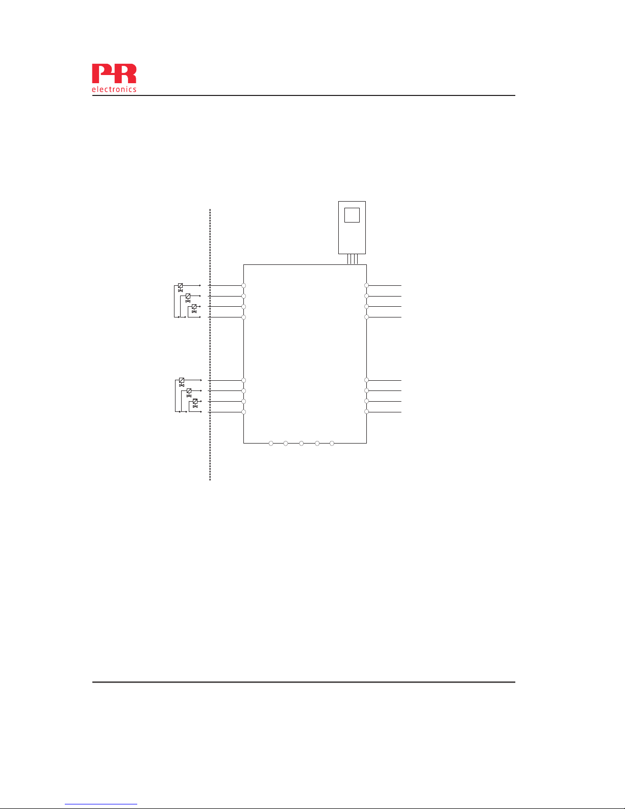
9203QB01
LERBAKKEN 10, 8410 RØNDE DENMARK
Revision date:
2013-05-31
Version Revision
V5 R0
Prepared by:
PB
Page:
2/3
Área de Risco Área de não Risco
Zona 0, 1, 2, 20, 21, 22 ou Zona 2
Terminal (31,32) Terminais (11,12 e 13,14)
Fonte: Entrada:
Voltagem 19,2 – 31,2 VDC Voltagem máx. 28,VDC
Potência máx. 3,5 W Gatilho: NPN Baixo < 2,V, Alto > 4,V
Gatilho: PNP Baixo < 8,V, Alto > 10,V
Terminais (33,34)
Relê de Estado: Área de não Risco Instalação Zona 2
Voltagem máx. 125 VAC / 110 VDC 32 VAC / 32 VDC
Potência máx. 62,5 VA / 32 W 16 VA / 32 W
Corrente máx. 0,5 AAC / 0,3 ADC 0,5 AAC / 1 ADC
Fonte / Entrada
(terminais 11,12,13,14)
(terminais 31,32,33,34)
(terminais 91,92,93,94,95)
Um: 253 V, máx. 400 Hz
-20 ≤ Ta ≤ 60ºC
44
43
42
41
54
53
52
51
34
33
32
31
14
13
12
11
9203
4501
91 92 93 94 95
TRILHO DE ENERGIA
9203 - Versão do produto 9203-002 29
Page 32
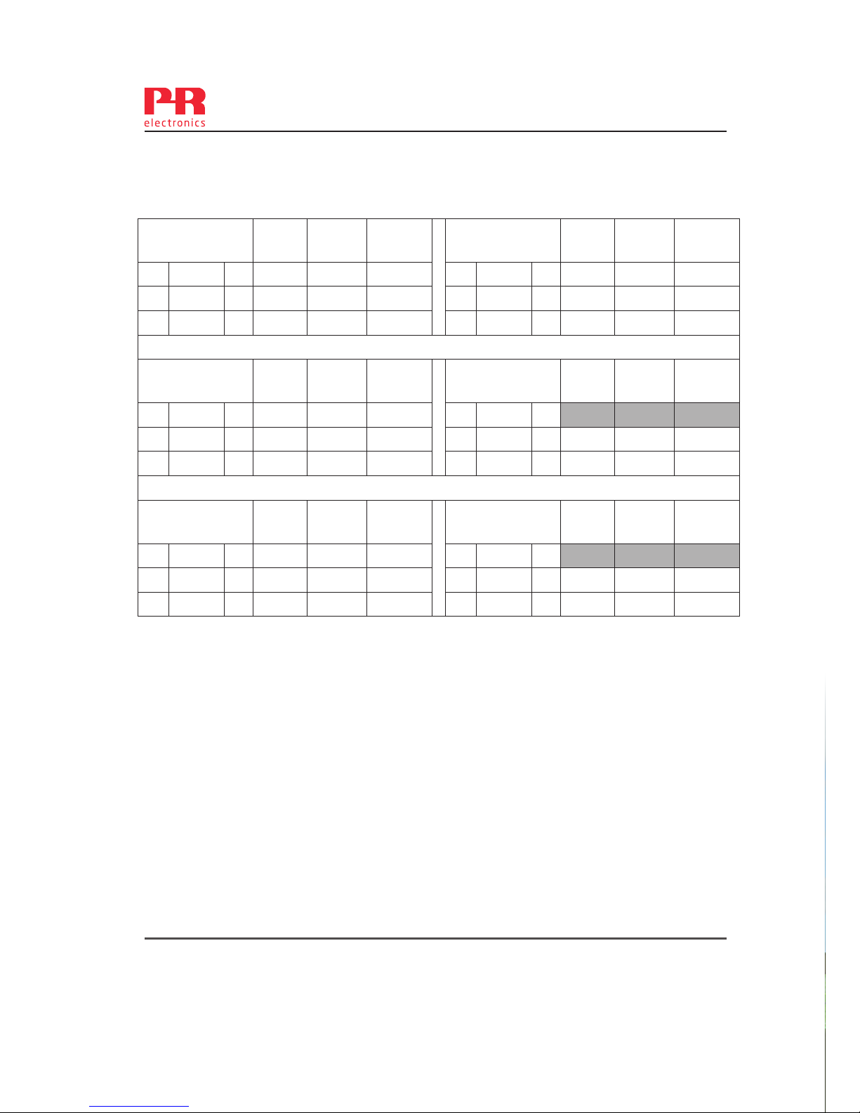
9203QB01
LERBAKKEN 10, 8410 RØNDE DENMARK
Revision date:
2013-05-31
Version Revision
V5 R0
Prepared by:
PB
Page:
3/3
9203B1A, 9203B1B
Terminais 41-42/51-
52
Co Lo Lo/Ro
9203B2A
Terminais 41-42
Co Lo Lo/Ro
Uo
28V IIC 80nF 4.2mH 54µH/Ω
Uo
28V IIC 80nF 2.69mH 44µH/Ω
Io
93 mA IIB 640nF 16.8mH 218µH/Ω
Io
115mA IIB 640nF 10.8mH 176µH/Ω
Po
0.65W IIA 2.1µF 32.6mH 436µH/Ω
Po
0.81W IIA 2.1µF 20.8mH 353µH/Ω
9203B1A, 9203B1B
Terminais 41-43/51-
53
Co Lo Lo/Ro
9203B2A
Terminais 41-43
Co Lo Lo/Ro
Uo
28V IIC 80nF 3.5mH 50µH/Ω
Uo
28V IIC
Io
100mA IIB 640nF 14.2mH 201µH/Ω
Io
125mA IIB 640nF 9.1mH 163µH/Ω
Po
0.70W IIA 2.1µF 27.6mH 402µH/Ω
Po
0.88W IIA 2.1µF 17.6mH 327µH/Ω
9203B1A,9203B1B
Terminais 41-44/51-
54
Co Lo Lo/Ro
9203B2A
Terminais 41-44
Co Lo Lo/Ro
Uo
28V IIC 80nF 2.9mH 46µH/Ω
Uo
28V IIC
Io
110mA IIB 640nF 11.8mH 184µH/Ω
Io
135mA IIB 640nF 7.8mH 150µH/Ω
Po
0.77W IIA 2.1µF 22.8mH 369µH/Ω
Po
0.95W IIA 2.1µF 15.1mH 301µH/Ω
Page 33

Version No. V4R0
SAFETY MANUAL
SOLENOID / ALARM DRIVER
9203
This safety manual is valid for the following product versions:
9203-001
9203-002
Page 34

Version No. V4R0 1
9203 Solenoid / Alarm Driver Safety Manual
1. Observed standards ................................................................................ 2
2. Acronyms and abbreviations ................................................................... 2
3. Purpose of the product ........................................................................... 3
4. Assumptions and restrictions for use of the product.............................. 3
4.1 Basic safety specifications ............................................................. 3
4.2 Associated equipment .................................................................... 3
4.2.1 Safety output ....................................................................... 3
4.2.2 Safety input ......................................................................... 3
4.3 Failure rates .................................................................................... 3
4.4 Safe parameterisation ..................................................................... 4
4.5 Installation in hazardous areas ....................................................... 4
5. Functional specification of the safety functions...................................... 4
6. Functional specification of the non-safety functions .............................. 4
7. Safety parameters ................................................................................... 4
8. Hardware and software configuration ..................................................... 5
9. Failure category ....................................................................................... 5
10. Periodic proof test procedure ................................................................. 5
11. Procedures to repair or replace the product ........................................... 5
12. Maintenance ............................................................................................ 5
13. Documentation for routing diagram ........................................................ 6
13.1 In general ........................................................................................ 6
13.2 Further explanations ....................................................................... 6
13.2.1 Password protection ........................................................... 6
13.4 Advanced functions ........................................................................ 6
13.4.1 Display setup ...................................................................... 7
13.4.2 Password ............................................................................ 7
13.4.3 Language ............................................................................ 7
13.4.4 Power rail ............................................................................ 7
13.4.5 Safety integrity level ............................................................ 7
14 Safe parameterisation - user responsibility ............................................. 8
14.1 Safety-related configuration parameters ........................................ 8
14.2 Verification procedure ..................................................................... 8
14.2.1 If no password is set ........................................................... 8
14.2.2 If password is set ................................................................ 9
14.3 Functional test ................................................................................ 9
15. Fault reaction and restart condition ........................................................ 9
16 User interface .......................................................................................... 10
16.1 Scrolling help texts in display line 3 ............................................... 10
16.3 Routing diagram - Advanced settings (ADV.SET)........................... 12
17 Connections diagram .............................................................................. 13
0. CONTENTS
Page 35

2 Version No. V4R0
Safety Manual 9203 Solenoid / Alarm Driver
1. Observed standards
2. Acronyms and abbreviations
Acronym /
Abbreviation
Designation Description
Element
Term defined by IEC 61508 as “part of a
subsystem comprising a single component
or any group of components that performs
one or more element safety functions”
PFD
Probability of
Failure on Demand
This is the likelihood of dangerous safety
function failures occurring on demand.
PFH
Probability of dan-
gerous Failure per
Hour
The term “Probability” is misleading, as IEC
61508 defines a Rate.
SFF
Safe Failure
Fraction
Safe Failure Fraction summarises the
fraction of failures which lead to a safe
state and the fraction of failures which will
be detected by diagnostic measures and
lead to a defined safety action.
SIF
Safety Integrity
Function
Function that provides fault detection (to
ensure the necessary safety integrity for the
safety functions)
SIL
Safety Integrity
Level
The international standard IEC 61508
specifies four discrete safety integrity levels
(SIL 1 to SIL 4). Each level corresponds to
a specific probability range regarding the
failure of a safety function.
Standard Description
IEC 61508
Functional Safety of electrical / electronic / programmable
electronic safety-related systems
IEC 61508-
2:2000
Part 2: Requirements for electrical / electronic / programmable
electronic safety-related systems
IEC 61508-
3:1998
Part 3: Software requirements
IEC 61326-
3-1:2008
Immunity requirements for safety-related systems
Page 36

Version No. V4R0 3
9203 Solenoid / Alarm Driver Safety Manual
3. Purpose of the product
Universal Ex driver for the control of solenoids etc. with various Ex data by
way of three built-in Ex barriers.
The device can be mounted in the safe area and in zone 2 / div. 2 and
transmit signals to zone 0, 1, 2, 20, 21 and 22.
Ex driver for the control of ON / OFF solenoids, acou stic alarms and LEDs
mounted in the hazardous area.
The 9203 is controlled by an NPN/PNP signal or a switch signal.
Monitoring of internal error events via the individual status relay and/or a
collective electronic signal via the power rail.
The 9203 has been designed, developed and certified for use in SIL 2
applications according to the requirements of IEC 61508.
4. Assumptions and restrictions for use of the product
4.1 Basic safety specifications
Operational temperature range ..... -20...+60°C
Storage temperature range ........... -20...+85°C
Power supply type, min. ................ Double or reinforced
Supply voltage ............................... 19.2...31.2 VDC
Mounting area ................................ Zone 2 / Division 2 or safe area
Mounting environment ................... Pollution degree 2 or better
4.2 Associated equipment
4.2.1 Safety output
The safety output shall be connected to the equipment with a
minimum load of 10 KΩ
4.2.2 Safety input
The safety input signal frequency shall not be higher than 20 Hz,
and the pulse length shall not be shorter than 25 ms.
4.3 Failure rates
The basic failure rates from the Siemens standard SN 29500 are used
as the failure rate database.
Failure rates are constant, wear-out mechanisms are not included.
External power supply failure rates are not included.
Page 37

4 Version No. V4R0
Safety Manual 9203 Solenoid / Alarm Driver
4.4 Safe parameterisation
The user is responsible for verifying the correctness of the configuration
parameters. (See section 14 Safe parameterisation - user responsibility).
Manual override may not be used for safety applications.
4.5 Installation in hazardous areas
The IECex Installation drawing, ATEX Installation drawing and FM
Installation drawing shall be followed if the products are installed in
hazardous areas.
5. Functional specification of the safety functions
Ex driver for the control of ON / OFF solenoids, acou stic alarms and LEDs
mounted in the hazardous area.
6. Functional specification of the non-safety functions
The status relay (terminal 33 and 34), error signal on power rail (terminal 91)
and LED outputs are not suitable for use in any Safety Instrumented Function.
7. Safety parameters
Note1: The 9203 contains no lifetime limiting components, therefore the PFH
figures are valid for up to 12 years, according to IEC 61508.
B1A, B1B B2A
Probability of dangerous Failure per Hour (PFH) 4.30E-08 4.60E-08
Note
1
Probability of failure on demand (PFD) -
1 year proof test interval
2.73E-04 2.92E-04
Proof test interval (10% of loop PFD) 5 years
4 years
Safe Failure Fraction 91% 91%
Demand response time
<10
ms
Demand mode High
Demand rate 1000 s
Mean Time To Repair (MTTR) 24 hours
Diagnostic test interval 10 seconds
Hardware Fault Tolerance (HFT) 0
Component Type B
SIL capability SIL 2
Description of the “Safe State” De-energised
Page 38

Version No. V4R0 5
9203 Solenoid / Alarm Driver Safety Manual
8. Hardware and software configuration
All configurations of software and hardware versions are fixed from factory,
and cannot be changed by end-user or reseller.
This manual only covers products labelled with the product version (or range
of versions) specified on the front page.
9. Failure category
10. Periodic proof test procedure
This test will detect approximately 95% of possible “du” (dangerous undetected)
failures in the device. The proof test is equivalent to the functional test.
11. Procedures to repair or replace the product
Any failures that are detected and that compromise functional safety should
be reported to the sales department at PR electronics A/S.
Repair of the device and replacement of circuit breakers must be done by
PR electronics A/S only.
12. Maintenance
No maintenance required.
Step Action
1 Bypass the safety PLC or take other appropriate action to avoid a false trip
2
Connect a simulator identical to the input setup
3
Perform an ON / OFF signal for each channel
4
Observe whether the output channel acts as expected
5
Restore the input terminals to full operation
6
Remove the bypass from the safety PLC or otherwise restore normal
operation
Failure category
Failure rates (1/h)
B1A, B1B B2A
Fail Safe Detected 0.00E+00 0.00E+00
Fail Safe Undetected 4.77E-07 4.80E-07
Fail Dangerous Detected 0.00E+00 0.00E+00
Fail Dangerous Undetected 4.30E-08 4.60E-08
Page 39

6 Version No. V4R0
Safety Manual 9203 Solenoid / Alarm Driver
13. Documentation for routing diagram
The routing diagram is shown in section 16.2.
13.1 In general
When configuring the 9203, you will be guided through all parameters
and you can choose the settings which fit the application. For each
menu there is a scrolling help text which is automatically shown in line
3 on the display.
Configuration is carried out by use of the 3 function keys:
1 will increase the numerical value or choose the next parameter
2will decrease the numerical value or choose the previous parameter
3will accept the chosen value and proceed to the next menu
When configuration is completed, the display will return to the default
state 1.0.
Pressing and holding
3 will return to the previous menu or return to the
default state (1.0) without saving the changed values or parameters.
If no key is activated for 1 minute, the display will return to the default
state (1.0) without saving the changed values or parameters.
13.2 Further explanations
13.2.1 Password protection
Access to the configuration can be blocked by assigning
a password. The password is saved in the device in order
to ensure a high degree of protection against unauthorised
modifications to the configuration. Default password 2008
allows access to all configuration menus.
Password protection is mandatory in SIL applications.
13.4 Advanced functions
The unit gives access to a number of advanced functions which can be
reached by answering “Yes” to the point “adv.set”.
Page 40

Version No. V4R0 7
9203 Solenoid / Alarm Driver Safety Manual
13.4.1 Display setup
Here you can adjust the brightness contrast and the backlight.
Setup of tag numbers with 5 alphanumerics. Selection of
functional readout in line 2 and 3 of the display - choose between
readout of digital output or tag no. When selecting ”ALT” the
readout toggles between digital output and tag no.
13.4.2 Password
Here you can choose a password between 0000 and 9999 in
order to protect the device against unauthorised modifications
to the configuration. The device is delivered default without
password.
13.4.3 Language
In the menu ”LANG” you can choose between 7 different
language versions of help texts that will appear in the menu. You
can choose between UK, DE, FR, IT, ES, SE and DK.
13.4.4 Power rail
In the menu ”RAIL” you can choose if errors in the device are
transmitted to the central surveillance in the PR 9410 power
control unit.
13.4.5 Safety integrity level
See Safe parameterisation - user responsibility
Page 41
8 Version No. V4R0
Safety Manual 9203 Solenoid / Alarm Driver
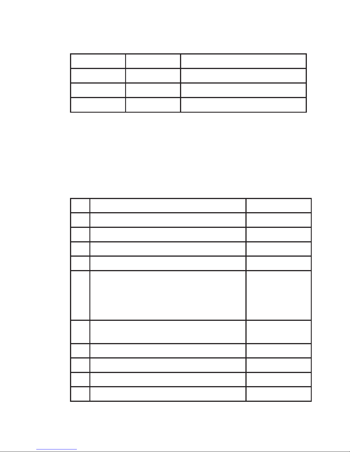
14 Safe parameterisation - user responsibility
14.1 Safety-related configuration parameters
Parameters Value Description
CH1.FUN DIR / INV Direct / inverted channel function
CH2.FUN. DIR / INV Direct / inverted channel function
PASSW 0 - 9999 New password
The above safety-related configuration parameters are marked in red
text in the routing diagrams and must be verified by the user in a SILconfiguration.
14.2 Verification procedure
The verification is done using the display / programming front PR 4501
by following the procedure described below.
14.2.1 If no password is set
Action Display shows
1 Press OK ADV.SET
2 Set (ADV.SET) to Yes and press OK DISP SETUP
3 Step down to (SIL SETUP) and press OK EN.SIL
4 Set (EN SIL) to YES and press OK NEW.PASS
5 Set password to a number between 0 and
9999 and press OK
(At this time the device starts operating in
SIL mode with the entered configuration
parameters!)
VerifyOPEN
”briefly”
LOCK*
6 Press OK to confirme verification of the
OPEN-LOCK in the display
CH1.FUN
7 Verify Channel 1 function and press OK CH2:FUN
8 Verify Channel 2 function and press OK PASSW
9 Verify password and press OK SIL.OK
10 Verify SIL and press OK
* Open is shown briefly in the display.
Page 42
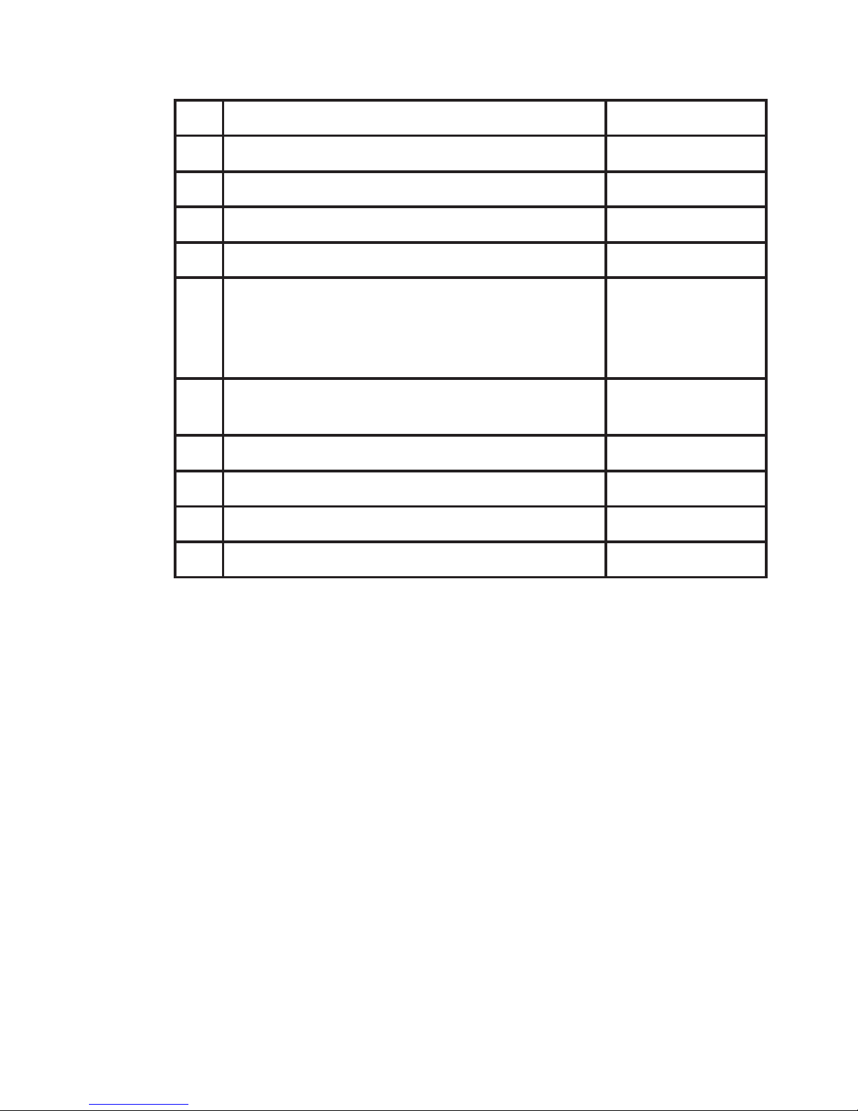
Version No. V4R0 9
9203 Solenoid / Alarm Driver Safety Manual
14.2.2 If password is set
Action Display shows
1 Press OK PASSW
2 Enter password and press OK ADV.SET
3 Set (ADV.SET) to Yes and press OK DISP SETUP
4 Step down to (SIL SETUP) and press OK EN.SIL
5 Set (EN SIL) to YES and press OK
(At this time the device starts operating in
SIL mode with the entered configuration
parameters!)
VerifyOPEN
”briefly”
LOCK*
6 Press OK to confirme verification of the
OPEN-LOCK in the display
CH1.FUN
7 Verify Channel 1 function and press OK CH2:FUN
8 Verify Channel 2 function and press OK PASSW
9 Verify password and press OK SIL.OK
10 Verify SIL and press OK
* Open is shown briefly in the display
14.3 Functional test
The user is responsible for making a functional test after verification of
safety parameters. The procedure for periodic proof test described in
section 10 shall be used.
15. Fault reaction and restart condition
When the 9203 detects a fault the output will go to Safe State, in which the
safety output will go to ”de-energised”.
For device faults there are 2 ways of bringing the device out of Safe State.
1. Power cycle the device.
2. Bring the device out of SIL mode (choose “NO” in the menu point ”EN.
SIL”), and set it back to SIL mode again (choose “YES” in the menu point
“EN.SIL” and verify the configuration).
Page 43

10 Version No. V4R0
Safety Manual 9203 Solenoid / Alarm Driver
16 User interface
16.1 Scrolling help texts in display line 3
[[01]
[02]
[06]
[07]
[09]
[10]
[11]
[12]
[13]
[14]
[15]
[16]
[17]
[20]
[21]
[22]
Set correct password
Enter advanced setup?
Enter language setup
Enter password setup
Enter display setup
Enter SIL setup
Select direct channel function
Select inverted channel function
Adjust LCD contrast
Adjust LCD backlight
Write a 5-character channel tag
Show output state in display
Show output load in display
Show tag in display
Alternate information shown in display
Configuration SIL status (Open / Locked)
Enable SIL configuration lock
Enable password protection?
Set new password
Select language
No communication - check connections
EEprom error - check configuration
Hardware error
Page 44
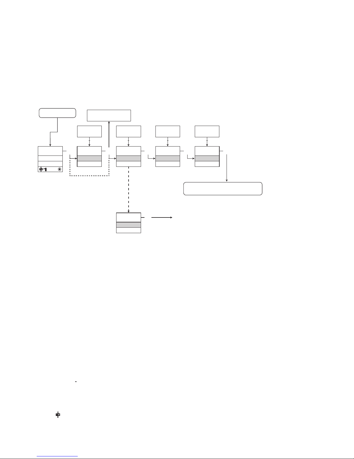
Power up
0000
PASSW.
Txt 1
ON
OFF
3
3
NO
ADV.SET
Txt 2
0000
9999
1 2
NO
YES
1 2
3
DIR
CH1.FUN
Txt 7
DIR
INV
1 2
3
YES
ADV.SET
Txt 2
3
DIR
CH2.FUN
Txt 7
1 2
3
DIR
INV
1.1
1.0
Directly to [EN.SIL]
if SIL-lock is enabled
Version No. V4R0 11
9203 Solenoid / Alarm Driver Safety Manual
Continued on the page
Routing diagram ADV.SET
To default state 1.0
ROUTING DIAGRAM
If no key is activated for 1 minute, the display will return to the default
state 1.0 without saving configuration changes.
1 Increase value / choose next parameter
2 Decrease value / choose previous parameter
3 Accept the chosen value and proceed to the next menu
Hold 3 Back to previous menu / return to menu 1.0 without saving
1.0 = Default state
Linie 1 shows status for channel 1
and channel 2.
Linie 2 shows output status for
channel 1, output current or tag no.
Linie 3 shows output status for
channel 2, output current or tag no.
Line 4 indicates whether the module
is SIL-locked.
1.1 = Only if password-protected.
1.2 If password has been set.
Line 1 symbols:
= OK. Flashing = error.
Line 2 and 3 symbols:
ON = channel 1 ON
OFF channel 2 OFF.
Line 4 symbols:
Static dot = SIL-locked.
Flashing dot = Not SIL-locked.
= output is active.
Page 45
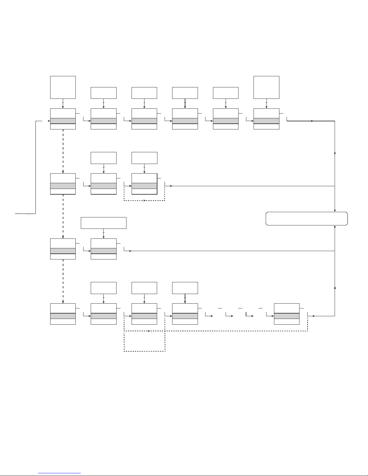
DISP,
PASS,
LANG,
SIL
1 2
DISP
SETUP
Txt 6
3
3
CONTRA
Txt 9
3
9
0
1 2
9
LIGHT
Txt 10
3
9
0
1 2
TAG1
VALVE 5
Txt 11
3
9
A
1 2
TAG2
VALVE 6
Txt 11
3
9
A
1 2
LANG
SETUP
Txt 06
3
UK
LANGUA
Txt 17
DE, DK, ES, FR,
IT, SE, UK
1 2
PASS
SETUP
Txt 06
3 3
YES
EN.PASS
Txt 15
3
YES
NO
1 2
NO
0000
NEW.PAS
Txt 16
3
9999
0000
1 2
SIL
SETUP
Txt 06
3
YES
EN.SIL
Txt 14
YES
NO
1 2
NO
3
2008
NEW.PAS
Txt 16
0000
9999
1 2
3
LOCK
CONFIG
Txt 13
SIL.OK
. . . . . . . . . . . . . .
3 3 3 3 3
3
LOAD
DISP
Txt 12
ALT
LOAD
TAG
D.OUT
1 2
3
3
LOCK
OPEN
1 2
To default state 1.0
Verify SIL configuration
1.2
12 Version No. V4R0
Safety Manual 9203 Solenoid / Alarm Driver
16.3 Routing diagram - Advanced settings (ADV.SET)
Page 46
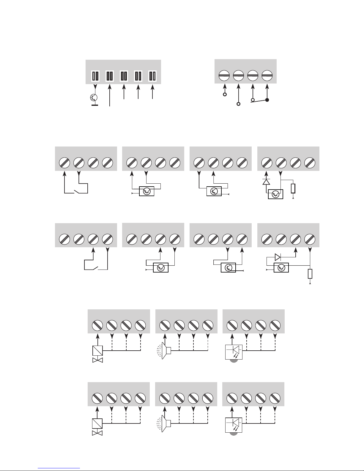
Version No. V4R0 13
9203 Solenoid / Alarm Driver Safety Manual
17 Connections diagram
41 42 43 4441 42 43 44 41 42 43 44
51 52 53 54 51 52 53 54 51 52 53 54
11 12 13 14
11 12 13 14
V
+
11 12 13 14
V
+
11 12 13 14
V
+
V
+
R
D
11 12 13 14
11 12 13 14
V
+
11 12 13 14
V
+
11 12 13 14
V
+
R
D
31 32 33 34
+24 V
91 92 93 94 95
+24 V
Outputs:
Supply and
status relay
N.C.
Gnd.
NCNCGnd.
Error
Power rail
connections
Channel 1Channel 2
Special PNP
trig input
Inputs:
Channel 1
Channel 2
Switch PNP, switchNPN, switch
Acoustic alarm LED
Solenoid, ON / OFF Acoustic alarm LED
Solenoid, ON / OFF
NC = No connection
Special PNP
trig inputSwitch PNP, switchNPN, switch
Page 47
Displays programáveis com uma grande
variedade de entradas e saídas para visualização de
temperatura, volume, peso, etc. Linearização de fábrica,
escala, e diferentes funções de medição para programação
via software PReset.
Displays
Uma grande variedade de transmissores
para montagem em trilho DIN B e módulos de trilho DIN
com comunicação de dados digitais e analógicos variando
para cada aplicação-específica de transmissores universais.
Temperatura
Isoladores galvânicos para sinais
analógicos e digitais bem como sinais HART
®
. Um grande
range de produtos, todos com loop de alimentação e
isoladores de sinais com linearização, inversão e escala de
sinais de saída.
Isolation
Interfaces para sinais analógicos e digitais
assim como sinais HART
®
entre sensores / conversores I/P /
sinais de frequência e sistemas de controle em zona Ex 0, 1
& 2 e para alguns módulos em zona 20, 21 & 22.
Interfaces Ex
Módulos programáveis via PC ou
display frontal com opções universais para entrada,
saída e alimentação. Este range oferece um número de
configurações avançadas como processo de calibração,
linearização e auto diagnóstico.
Universal
Page 48

Head oce
Denmark www.prelectronics.com
DK-8410 Rønde fax +45 86 37 30 85
www.prelectronics.fr
[email protected]
www.prelectronics.de
[email protected]
www.prelectronics.es
[email protected]
www.prelectronics.it
[email protected]
www.prelectronics.se
[email protected]
www.prelectronics.co.uk
[email protected]
www.prelectronics.com
[email protected]
www.prelectronics.cn
[email protected]
 Loading...