

Page 1
9202
Impulsisolator
Nr. 9202V103-DE
Produktversion: 9202-003
SIGNALS THE BEST
Page 2

PR electronics A/S tilbyder et bredt program af analoge og digitale
DK
signalbehandlingsmoduler til industriel automation. Programmet
består af Isolatorer, Displays, Ex-barrierer, Temperaturtransmittere,
Universaltransmittere m. Vi har modulerne, du kan stole på i selv
barske miljøer med elektrisk støj, vibrationer og temperaturudsving, og alle produkter opfylder de strengeste internationale standarder. Vores motto »Signals the Best« er indbegrebet af denne
loso – og din garanti for kvalitet.
PR electronics A/S offers a wide range of analogue and digital
UK
signal conditioning modules for industrial automation. The product
range includes Isolators, Displays, Ex Interfaces, Temperature
Transmitters, and Universal Modules. You can trust our products
in the most extreme environments with electrical noise, vibrations
and temperature uctuations, and all products comply with the
most exacting international standards. »Signals the Best« is the
epitome of our philosophy – and your guarantee for quality.
PR electronics A/S offre une large gamme de produits pour le
FR
traite ment des signaux analogiques et numériques dans tous
les domaines industriels. La gamme de produits s’étend des
transmetteurs de température aux afcheurs, des isolateurs aux
interfaces SI, jusqu’aux modules universels. Vous pouvez compter
sur nos produits même dans les conditions d’utilisation sévères,
p.ex. bruit électrique, vibrations et uctuations de température.
Tous nos produits sont conformes aux normes internationales les
plus strictes. Notre devise »SIGNALS the BEST« c’est notre ligne
de conduite - et pour vous l’assurance de la meilleure qualité.
PR electronics A/S verfügt über ein breites Produktprogramm
DE
an analogen und digitalen Signalverarbeitungsmodule für die industrielle Automatisierung. Dieses Programm umfasst Displays,
Temperaturtransmitter, Ex- und galvanische Signaltrenner, und
Universalgeräte. Sie können unsere Geräte auch unter extremen
Einsatzbedingungen wie elektrisches Rauschen, Erschütterungen
und Temperaturschwingungen vertrauen, und alle Produkte von
PR electronics werden in Überein stimmung mit den strengsten
internationalen Normen produziert. »Signals the Best« ist Ihre
Garantie für Qualität!
1226
Page 3

IMPULSISOLATOR
9202
INHALTSVERZEICHNIS
Warnung ............................................................................. 2
Zeichenerklärungen ............................................................ 2
Sicherheitsregeln ................................................................ 2
Zerlegung des Systems 9000 ............................................ 4
EG-Konformitätserklärung .................................................. 5
Erweiterte Merkmale .......................................................... 6
Verwendung ........................................................................ 6
Technishe Merkmale........................................................... 6
Anwendungen ................................................................... 7
PR 4501 Display / Programmierfront ................................. 8
Bestellangaben: 9202B ...................................................... 9
Elektrische Daten ............................................................... 9
Konfiguration der Kabelfehlerüberprüfung ......................... 11
Funktionsbeschreibung ...................................................... 12
Anschlüsse ......................................................................... 13
Blockdiagramm .................................................................. 14
Signalfehler- und Kabelfehler Erkennung
ohne Frontdisplay ............................................................ 15
Konfiguration / Bedienung der Funktionstasten ................ 16
Scrollender Hilfstext im Display Zeile 3 ............................. 18
FlussDiagramm, erweiterte einstellungen (ADV.SET) ......... 20
Appendix ............................................................................ 21
IECEx Installation Drawing .............................................. 22
ATEX Installationszeichnung ............................................ 24
FM Installation Drawing ................................................... 26
Safety Manual .................................................................. 28
9202 - Product Version 9202-003 1
Page 4
Die folgende Maßnahmen sollten nur in spannungslosem
WARNUNG
Zustand des Gerätes und unter ESD-sicheren Verhältnisse
durchgeführt werden:
Installation, Montage und Demontage von Leitungen.
Fehlersuche im Gerät.
Reparaturen des Gerätes und Austausch von Sicherungen
dürfen nur von PR electronics A/S vorgenommen werden.
Die Frontplatte des Gerätes darf nicht geöffnet werden, weil
hier durch die Kontakte zur Kontaktierung des Frontdisplays
4501 beschädigt werden können. Das Gerät enthält keine internen DIP-Schalter oder Programmierbrücken.
ZEICHENERKLÄRUNGEN
WARNUNG
Dreieck mit Ausrufungszeichen: Das Handbuch ist sorgfältig
durchzulesen vor Montage und Inbetriebnahme des Gerätes, um
schweren Verletzungen oder mechanischer Zerstörung zu vermeiden.
Die CE-Marke ist das sichtbare Zeichen dafür, dass das Gerät die Vorschriften erfüllt.
Doppelte Isolierung ist das Symbol dafür, dass das Gerät besondere
Anforderungen an die Isolierung erfüllt.
Ex-Geräte sind entsprechend der ATEX Direktive für die Verwendung in Verbindung mit Installationen in explosionsgefährdeter Umgebung zuge lassen.
SICHERHEITSREGELN
DEFINITIONEN
Gefährliche Spannungen sind definitionsgemäß die Bereiche: 75...1500 Volt
Gleichspannung und 50...1000 Volt Wechselspannung.
Techniker sind qualifizierte Personen, die dazu ausgebildet oder angelernt sind,
eine Installation, Bedienung oder evtl. Fehlersuche auszuführen, die sowohl
technisch als auch sicherheitsmäßig vertretbar ist.
Bedienungspersonal sind Personen, die im Normalbetrieb mit dem Produkt die
Drucktasten oder Potentiometer des Produktes einstellen bzw. bedienen und
die mit dem Inhalt dieses Handbuches vertraut gemacht wurden.
9202 - Product Version 9202-003 2
Page 5

EMPFANG UND AUSPACKEN
Packen Sie das Gerät aus, ohne es zu beschädigen und kontrollieren Sie beim
Empfang, ob der Gerätetyp Ihrer Bestellung entspricht. Die Ver packung sollte
beim Gerät bleiben, bis dieses am endgültigen Platz montiert ist.
UMGEBUNGSBEDINGUNGEN
Direkte Sonneneinstrahlung, starke Staubentwicklung oder Hitze, mechanische
Erschütterungen und Stöße sind zu vermeiden; das Gerät darf nicht Regen
oder starker Feuchtigkeit ausgesetzt werden. Bei Bedarf muss eine Erwärmung,
welche die angegebenen Grenzen für die Umgebungstemperatur überschreitet,
mit Hilfe eines Kühlgebläses verhindert werden.
Das Gerät muss im Verschmutzungsgrad 2 oder besser installiert werden.
Das Gerät ist so konzipiert, dass es auch in einer Einsatzhöhe von bis zu
2 000 m noch sicher funktioniert.
INSTALLATION
Das Gerät darf nur von Technikern angeschlossen werden, die mit den technischen Ausdrücken, Warnungen und Anweisungen im Handbuch vertraut sind
und diese befolgen.
Sollten Zweifel bezüglich der richtigen Handhabung des Gerätes bestehen,
sollte man mit dem Händler vor Ort Kontakt aufnehmen. Sie können aber auch
direkt mit
Der Einsatz von verdrillter Leitung ist nicht erlaubt außer die Enden sind mit
Aderendhülsen versehen.
Eine Beschreibung von Eingangs- / Ausgangs- und Versorgungsanschlüssen
befindet sich auf dem Blockschaltbild und auf dem seitlichen Schild.
Das Gerät ist mit Feldverdrahtungsklemmen ausgestattet und wird von einem
Netzteil mit doppelter / verstärkter Isolierung versorgt. Der Netzschalter sollte
leicht zugänglich und in der Nähe des Gerätes sein. Der Netzschalter sollte mit
einem Schild gekennzeichnet sein, auf dem steht, dass durch Betätigung dieses
Schalters das Gerät vom Netz genommen wird.
Für den Anschluss auf der Power Rail 9400 wird das Gerät über das Power
Control Unit 9410 versorgt.
Die ersten beiden Ziffern der Seriennummer geben das Produktionsjahr an.
PR electronics GmbH
www.prelectronics.de
9202 - Product Version 9202-003 3
Page 6
KALIBRIERUNG UND JUSTIERUNG
Während der Kalibrierung und Justierung sind die Messung und der Anschluss
externer Spannungen entsprechend diesem Handbuch auszuführen, und
der Techniker muss hierbei sicherheitsmäßig einwandfreie Werkzeuge und
Instrumente benutzen.
BEDIENUNG IM NORMALBETRIEB
Das Bedienungspersonal darf das Gerät nur dann einstellen oder bedienen,
wenn diese auf vertretbare Weise in Schalttafeln o. ä. fest installiert sind, sodass
die Bedienung keine Gefahr für Leben oder Material mit sich bringt. D. h., es
darf keine Gefahr durch Berührung bestehen, und das Gerät muss so plaziert
sein, dass es leicht zu bedienen ist.
REINIGUNG
Das Gerät darf in spannungslosem Zustand mit einem Lappen gereinigt werden,
der mit destilliertem Wasser leicht angefeuchtet ist.
HAFTUNG
In dem Umfang, in welchem die Anweisungen dieses Handbuches nicht
genau eingehalten werden, kann der Kunde PR electronics gegenüber keine
Ansprüche geltend machen, welche ansonsten entsprechend der eingegangenen Verkaufsvereinbarungen existieren können.
ZERLEGUNG DES SYSTEMS 9000
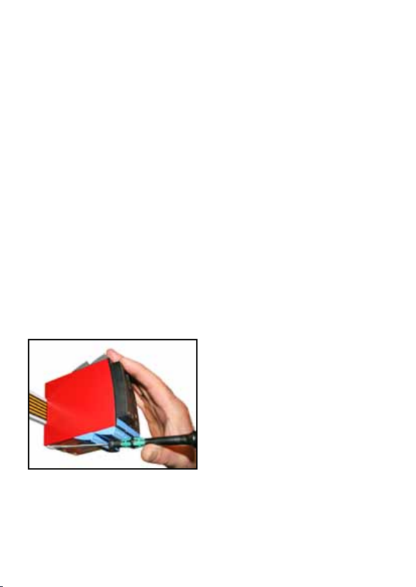
Abbildung 1:
Das Gerät wird von der Power Rail
gelöst, indem man den unteren
Verschluss löst.
9202 - Product Version 9202-003 4
Page 7

EG-KONFORMITÄTSERKLÄRUNG
Als Hersteller bescheinigt
PR electronics A/S
Lerbakken 10
DK-8410 Rønde
hiermit für das folgende Produkt:
Typ: 9202
Name: Impulsisolator
die Konformität mit folgenden Richtlinien und Normen:
Die EMV Richtlinien 2004/108/EG und nachfolgende Änderungen
EN 61326-1 : 2006
Zur Spezifikation des zulässigen Erfüllungsgrades, siehe die Elektrische
Daten des Gerätes.
Die Niederspannungsrichtlinien 2006/95/EG und nachfolgende Änderungen
EN 61010-1 : 2001
Die ATEX Richtlinien 94/9/EG und nachfolgende Änderungen
EN 60079-0 : 2009, EN 60079-11 : 2007, EN 60079-15 : 2005,
EN 60079-26 : 2007, EN 612 41-11 : 20 06
ATEX-Zertifikat: KEMA 07ATEX0146 X
Zulassungsstelle:
DEKRA Certification B.V. (0344)
Utrechtseweg 310, 6812 AR Arnhem
P.O. Box 5185, 6802 ED Arnhem
The Netherlands
Rønde, 7. Februar 2012 Kim Rasmussen
Unterschrift des Herstellers
9202 - Product Version 9202-003 5
Page 8

IMPULSISOLATOR
9202
• Schnittstelle für NAMUR-Sensoren und Schalter
• Erweiterte Selbstdiagnose und Erkennung von
Kabelfehlern
• 1 oder 2 Kanäle
• Kann separat über Klemmenanschluss oder über die
Power Rail 9400 versorgt werden
• SIL 2-zertifiziert über Full Assessment
Erweiterte Merkmale
• KonfigurationundÜberwachungüberdasabnehmbareFrontdisplay(PR4501).
• AuswahleinerdirektenoderinvertiertenFunktionfürjedenKanalmitPR4501.
• ErweiterteÜberwachungderinternenKommunikationundgespeichertenDaten.
• OptionalredundanteVersorgungüberPowerRailund/oderseparate
Versorgung.
• SIL2-FunktionalitätistoptionalundmussübereinenMenüpunktaktiviert
werden.
Verwendung
• DasGerätkanninsicherenBereichenundinZone2/div.2eingesetztwerden und Signale aus Zone 0, 1, 2, 20, 21, 22 sowie M1 / Class I/II/III, Div. 1,
Gr. A-G aufnehmen.
•ImpulsisolatorzurÜbertragungvonSignalenvonNAMUR-Sensorenund
mechanischen Schaltern aus dem Ex-Bereich zum sicheren Bereich.
•KontrollevonFehlernundKabelbruchüberdaseinzelneStatusrelaisund/
oder eine gemeinsame elektronische Sammelmeldung über die Power Rail.
•DerImpulsisolator9202wurdeentwickeltundzertifiziertfürSIL
2-Anwendungen entsprechend den Anforderungen der Richtlinie IEC 61508.
Technishe Merkmale
• 1grüneund2gelbe/roteLeuchtdiode in der Front des Gerätes zeigt den normalen Betrieb und Fehlfunktionen an.
• 2,6kVACgalvanische Trennung zwischen EIngang, Ausgang und Versorgung.
9202 - Product Version 9202-003 6
Page 9
Eingangs-
Erde -
signale:
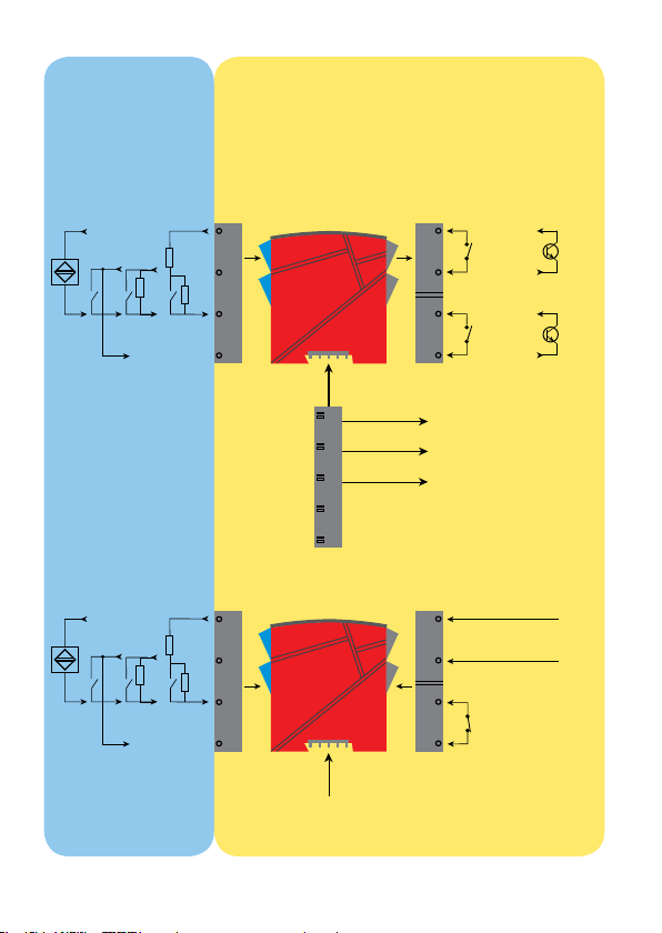
ANWENDUNGEN
Ausgangssignale:
Kanal 1:
NAMUR
+
-
Kanal 2:
NAMUR
+
-
Zone 0, 1, 2,
20, 21, 22, M1 &
Cl. I/II/III, div. 1
gr. A-G
Mecha-
nisher
Schalter
R
p
Mecha-
nisher
Schalter
R
p
44
R
s
43
R
p
42
41
Power rail
54
R
s
53
R
p
52
51
Versorgung über
Power Rail
Zone 2 / Cl. 1, Div. 2, Gr. A-D
14
13
12
11
Statusrelais-Signal
Rail, +24 VDC
Rail, Erde
Versorgungsanschluss:
31
Versorgung +19,2...31,2 VDC
32
Gerätestatus
33
34
Gerätestatus
oder sicheres Bereich
Relais
Relais
Relais
Relais
Kanal 2:
N.O. oder
N.C.
Kanal 1:
N.O. oder
N.C.
N.C.
Opto +
Kanal 2:
Opto -
Opto +
Kanal 1:
Opto -
9202 - Product Version 9202-003 7
Page 10
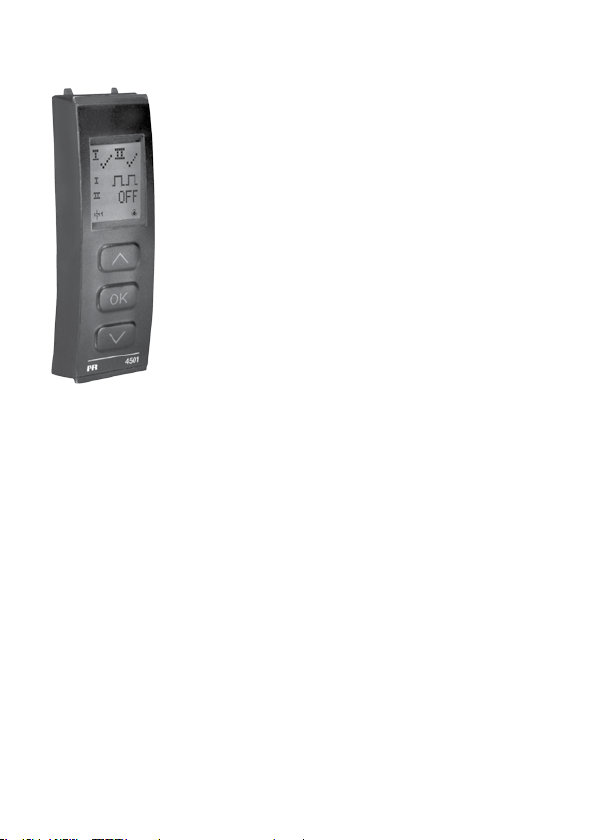
PR 4501 DISPLAY / PROGRAMMIERFRONT
Funktionallität
Die einfache Menüstruktur leitet automatisch durch
die relevanten Einstellungen. Der scrollende Hilfetext
macht es sehr einfach diese Geräte einzusetzen.
Sie finden weitere Beschreibungen der Funktionen
und Programmierungsmög lichkeiten im Abschnitt
”Konfiguration / Bedienung der Funktionstasten”.
Anwendungen
• KommunikationsschnittstellezurÄnderungderoperativenParameterim
9202.
• WenndasGerätimProzessintegriertist,zeigtdasDisplaydieentsprechenden Prozesswerte und den jeweiligen Prozessstatus an.
Technische Merkmale
• LCDDisplaymit4Zeilen;Zeile1(5,57mmhoch)zeigtdenRelaisstatusjeder
Kanal (OK oder Fehler), Zeile 2 (3,33 mm hoch) den Ausgang für Kanal 1 (ON /
OFF), Zeile 3 (3,33 mm hoch) den Ausgang für Kanal 2 (ON / OFF) und Zeile
4 den Status der SIL-Konfiguration (offen / verriegelt) an. Statischer Punkt =
SIL-verriegelt, blinkender Punkt = nicht SIL-verriegelt. Zeile 4 zeigt auch den
Status für Relais 1 und Relais 2 an.
• ZumSchutzderjeweiligenKonfigurationgegenunbefugteÄnderungenkann
der Zugang zum Menü durch ein Passwort blockiert werden.
Montage / Installation
• Steckedas4501aufdieFrontdes9202.
9202 - Product Version 9202-003 8
Page 11
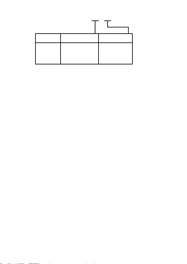
Bestellangaben: 9202B
Typ Schalter Kanäle
9202B Opto ...... : 1
Relais N.O. . : 2
Einfach .. : A
Zweifach. : B
Relais N.C. . : 3
4501 = Display / Programmierfront
9400 = Power Rail
Elektrische Daten
Umgebungstempeatur ................................ -20...+60°C
Lagertemperatur .......................................... -20...+85°C
Allgemeine Daten:
Versorgungsspannung, DC ......................... 19,2...31,2 VDC
Stromverbrauch, max. ................................. ≤ 3 W (2 Kanäle)
Sicherung .................................................... 400 mA T / 250 VAC
Isolationsspannungen, Test / Betrieb:
Eingänge / Ausgänge / Versorgung ..... 2,6 kVAC / 300 VAC verstärkt
Ausgang 1 zum Ausgang 2 .................. 1,5 kVAC / 150 VAC verstärkt
Statusrelais zur Versorgung ................. 1,5 kVAC / 150 VAC verstärkt
Kommunikationsschnittstelle ...................... Programmierfront 4501
Ansprechzeit für Kablefehler ....................... < 200 ms
Kalibrierungstemperatur .............................. 20...28°C
Hilfsspannungen:
NAMUR-Versorgung .................................... 8 VDC / 8 mA
Schwingungen, IEC 60068-2-6 ................... Test Fc, 1 g, 2...100 Hz
Schwingungen, kontinuierlich,
IEC 60068-2-64 ........................................... Test Fh, 1 g, 3...100 Hz
Leitungsquerschnitt ..................................... AWG 26...14 / 0,13...2,08 mm
Litzendraht
Klemmschraubenanzugsmoment ................ 0,5 Nm
Relative Luftfeuchtigkeit .............................. < 95% RF (nicht kond.)
Abmessungen, ohne Frontdisplay (HxBxT) .. 109 x 23,5 x 104 mm
Abmessungen, mit Frontdisplay (HxBxT) .... 109 x 23,5 x 116 mm
Schutzart ..................................................... IP20
Gewicht ....................................................... 170 g / 185 g mit 4501
2
9202 - Product Version 9202-003 9
Page 12

Eingänge:
Sensortypen:
NAMUR gemäß .................................... EN 60947-5-6
Mechanischer Schalter mit
Serien- (R
R
R
Frequenzbereich .......................................... 0...5 kHz
) und Parallel- (Rp) Widerstand:
s
......................................................... Nom. 750 Ω
s
......................................................... Nom. 15 kΩ
p
Impulslänge, min. ........................................ > 0,1 ms
Eingangswiderstand .................................... Nom. 1 kΩ
Trig-Niveau, Signal ...................................... < 1,2 mA, > 2,1 mA
Trig-Niveau, Kabelfehler .............................. < 0,1 mA, > 6,5 mA
Ausgänge:
Relaisausgänge:
Statusrelais:
Max. Spannung .................................... 125 VAC / 110 VDC
Max. Strom........................................... 0,5 A AC / 0,3 A DC
Max. Leistung....................................... 62,5 VA / 32 W
Relaisausgänge:
Max. Schaltungsfrequenz .................... 20 Hz
Max. Spannung .................................... 250 VAC / 30 VDC
Max. Strom........................................... 2 A AC / 2 A DC
Max. Leistung....................................... 500 VA / 60 W
Opto, NPN-Ausgänge:
Max. Schaltungsfrequenz .................... 5 kHz
Impulslänge, min. ................................. > 0,1 ms
Max. Belastung, Strom / Spannung. ... 80 mA / 30 VDC
Spannungsabfall bei 80 mA ................. < 2,5 VDC
Zulassungen:
EMC 2004/108/EG ...................................... EN 61326-1
LVD 2006/95/EG .......................................... EN 61010-1
UL, Standard for Safety .............................. UL 61010-1
GOST R
Marine:
Det Norske Veritas, Ships & Offshore ......... Stand. f. Certific. No. 2.4
I.S. / Ex:
ATEX 94/9/EG .............................................. KEMA 07ATEX0146 X
IECEx ........................................................... IECEx KEM 06.0039 X
c FM us ....................................................... 3034430-C
GOST Ex
9202 - Product Version 9202-003 10
Page 13

Funktionaler Sicherheit:
SIL 2-zertifiziert über Full Assessment gemäß IEC 61508
Konfiguration der Kabelfehlerüberprüfung
Kabelfehler Erkennung, unabhängige Erkennung und Visualisierung für jeden Kanal:
Module: Konfiguration, gebräuchlich für beide Kanäle Kabelfehler Erkennung:
9202
Eingang Vorfall Anzeige Grenze
Alle Kabelbruch CA.BR < 0,1 mA
Alle Kabel kurzgeschlossen CA.SH > 6,5 mA
CA.BR = Ja oder CA.SH = Ja ON
Kabelfehler Erkennung (CA.BR, CA.SH):
Diagnosen
Sonst: OFF
Kabelfehler Erkennung
9202 - Product Version 9202-003 11
Page 14

Hardware / Software Fehler
Kommunikationstest 4501 / 9202 NO.CO Verbindungsfehler
EEprom Fehler - überprüfe Konfiguration FL.ER
Hardware Fehler DE.ER
Hardware Fehler FC.ER
EEprom Fehler - überprüfe Konfiguration CO.ER
Hardware Fehler CA.ER Werkskalibrierungsfehler
Hardware Fehler HW.ER
Hardware Fehler OC.ER
Hardware Fehler MS.ER
Hardware Fehler MI.ER
Hardware Fehler MC.ER
! Alle Fehleranzeigen im Display blinken im Sekundentakt. Der Hilfstext erklärt den Fehler.
Im Falle eines Kabelfehlers blinkt die Beleuchtung ebenfalls. Reset mit der Taste 3.
Fehler die in beiden Kanälen auftreten werden als Fehler im Kanal 1 angezeigt – und die Anzeige
Kanal 2 ist leer.
Hardware Fehler können in zwei Arten zurückgesetzt werden. Erstens schrittweise durch das
Menü gehen (wenn der andere Kanal weiterarbeiten soll) oder kurzfristiges Wegschalten der
Versorgungsspannung.
Fehlersuche Anzeige Grund
Anzeige bei Hardware Fehler:
Konfigurationsfehler oder
CRC Versatz, gespeicherte
Konfiguration wird geladen
Ungültige Konfiguration
im Gerät
Ungültiger Code
Checksumme im 4501
Ungültige Konfiguration
(CRC oder Daten)
HW Setup - Konfiguration
Versatz
Main Output Controller
Kommunicationsfehler
Interne Hauptversorgung
außerhalb der Grenzen
Hauptinitalisierung
Selbsttest fehlerhaft
Main Flash oder RAM
Selbsttest fehlerhaft
FUNKTIONSBESCHREIBUNG
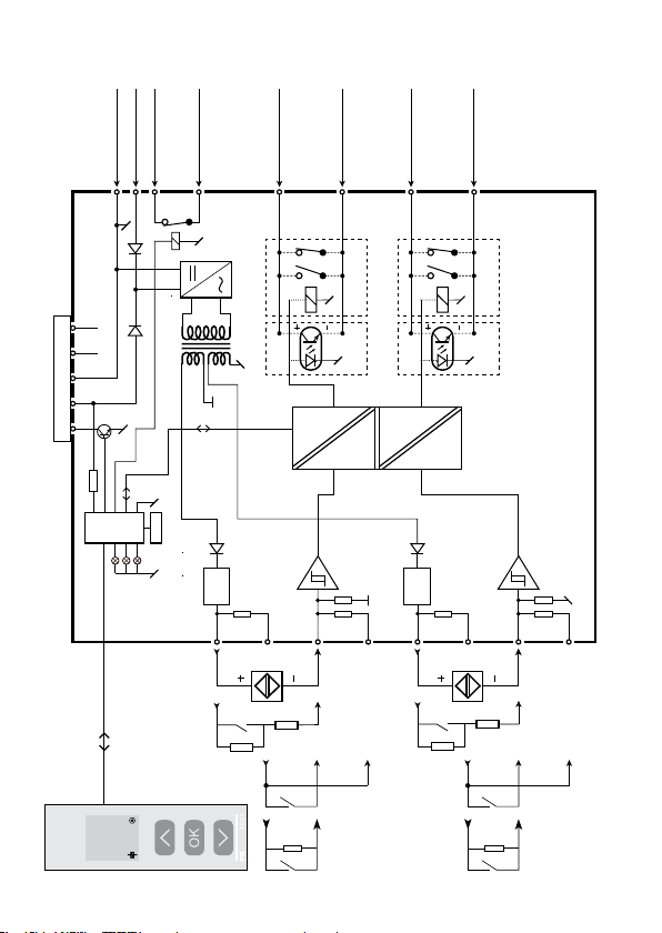
Verbindungsbeispiele auf Anschlussdiagramm und Blockdiagramm (1)...(4)
(1) NAMUR-Sensor mit Kabelfehlererkennung für Bruch und Kurzschluss.
(2) Mechanischer Schalter mit Kabelfehlererkennung für Bruch und Kurzschluss,
wenn Rs und Rp auf dem Schalter montiert ist.
(3) Mechanischer Schalter mit Kabelfehlererkennung für Bruch, wenn Rp auf
dem Schalter montiert ist
(4) Mechanischer Schalter ohne Kabelfehlererkennung.
9202 - Product Version 9202-003 12
Page 15
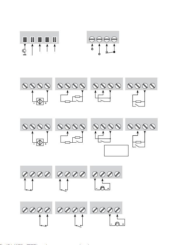
Power Rail
Verbindungen
91 92 93 94 95
ANSCHLÜSSE
Versorgung und
Statusrelais
31 32 33 34
Fehler
NC = Keine Verbindung
Kanal 1Kanal 2Kanal 1
Erde
+24 V
NCNC
Eingänge:
NAMUR-Sensor,
Kabelfehler (1)
41 42 43 44
NAMUR-Sensor,
Kabelfehler (1)
51 52 53 54
Relais, N.C. Opto, NPN
11 12 13 14
Relais, N.C. Opto, NPNRelais, N.O.
11 12 13 14
Schalter,
Kabelfehler (2)
41 42 43 44
R
p
R
s
Schalter,
Kabelfehler (2)
51 52 53 54
R
p
R
s
Ausgänge:
Relais, N.O.
11 12 13 14
11 12 13 14
Erde
N.C.
+24 V
Schalter, kein
Kabelfehler (4)
(1)...(4) = Siehe Funktionsbeschreibung auf Seite 12
Schalter, Kabel-
fehler, Bruch(3)
41 42 43 44 41 42 43 44
R
p
Schalter, kein
Kabelfehler (4)
Schalter, Kabel-
fehler, Bruch(3)
51 52 53 54 51 52 53 54
R
p
Rp = 15 kΩ
Rs = 750 Ω
11 12 13 14
11 12 13 14
Kanal 2
9202 - Product Version 9202-003 13
Page 16
NC*NC*
Power Rail Verbindungen
CPU
Erde -
Versorgung +24 VDC
31
323433
Erde
+24 V
BLOCKDIAGRAMM
Statusrelais N.C.
Statusrelais N.C.
FLASH
Opto + oder Relais N.O.
12
Kanal 1
oder Relais N.C.
Opto - oder Relais N.O.
11
oder Relais N.C.
Kanal 2
9202B1 9202B2...B3
Opto + oder Relais N.O.
oder Relais N.C.
Opto - oder Relais N.O.
oder Relais N.C.
14
13
9202B1 9202B2...B3
* NC = Keine Verbindung
9202
Gerätestatus, Grün
Kanal 1 Status, Gelb/Rot
Kanal 2 Status, Gelb/Rot
1
O F F
Kanal 1
44
Sensor
NAMUR-
Schalter,
Kabelfehler
NAMUR
V
43
42
s
R
p
R
p
R
(3) (4) (1)(2)
(3) (4) (1)(2)
NAMUR
V
Kanal 2
41
54
53
52
Sensor
NAMUR-
s
Schalter,
Kabelfehler
= 15 kΩ
p
R
R
p
R
p
R
(3) (4) (1)(2)
= 750 Ω
s
R
(3) (4) (1)(2)
9202 - Product Version 9202-003 14
51
(1)...(4) = Siehe Funktions-
beschreibung auf Seite 12
Page 17
Signalfehler- und Kabelfehler Erkennung ohne Frontdisplay
Power Rail
Signalstatus
N.C.
Statusrelais,
Kanal 2:
Gelb / Rot
Kanal 1:
Gelb / Rot
LED
Grüne
Liste der LED und Fehlersignalanzeigen
Status
Gerät OK Blinkt Angesteuert OFF
Keine Versorgung OFF OFF OFF Abgefallen ON
Gerät defekt OFF Rot Rot Abgefallen ON
Kanal 1. Relais angesteuert Blinkt Gelb Angesteuert OFF
Kanal 1, Relais abgefallen bei Kabelfehler Blinkt Rot blinkend Abgefallen ON (wenn aktiviert)
Kanal 1, Relais abgefallen Blinkt OFF Angesteuert OFF
Kanal 2, Relais angesteuert Blinkt Gelb Angesteuert OFF
Kanal 2, Relais abgefallen bei Kabelfehler Blinkt Rot blinkend Abgefallen ON (wenn aktiviert)
Kanal 2, Relais abgefallen Blinkt OFF Angesteuert OFF
9202 - Product Version 9202-003 15
Page 18

KONFIGURATION /
BEDIENUNG DER FUNKTIONSTASTEN
Dokumentation für das Flussdiagramm.
Grundsätzliches
Bei der Konfiguration des 9202 werden Sie durch alle Parameter geleitet und
Sie können die Einstellungen wählen, welche zur Applikation passt. Für jedes
Menü existiert ein scrollender Hilfetext welcher automatisch in der 3. Zeile im
Display gezeigt wird.
Die Konfiguration wird mittels der 3 Funktionstasten durchgeführt:
1 erhöht den numerischen Wert oder wählt nächsten Parameter
2setzt den numerischen Wert herab oder wählt nächsten Parameter
3übernimmt den gewählten Wert und beendet das Menü
Wenn eine Konfiguration eingegeben worden ist, kehrt das Display auf den
Menüpunkt 1.0 zurück
Bei drücken und halten von
in den Normal-Zustand (1.0) ohne die geänderten Werte oder Parameter zu
speichern.
Wenn für 1 Minute keine Taste betätigt wird, geht das Display in den Normal-
Zustand zurück, ohne die geänderten Werte oder Parameter zu speichern.
Weitere Erklärungen
Passwortschutz: Der Zugriff auf die Programmierung kann mit der Eingabe
eines Passwortes blockiert werden. Das Passwort wird im Gerät gespeichert,
um den höchsten Grad an Schutz gegen nicht autorisierte Änderungen der
Konfiguration sicherzustellen. Bei Eingabe des Master-Passwortes 2008 sind
alle Konfigurationsmenüs erreichbar.
Kabelfehlerinformation per Programmierfront 4501
Kabelfehler (s. Grenzen im Diagramm), wird als CA.BR (Kabelbruch) oder CA.SH
(Kabelkurzschluss) angezeigt. Kabelfehlererkennung wird unabhängig für
jeden Kanal angezeigt, aber die Konfiguration gilt für beide Kanäle. Im Falle
eines Kabelfehlers blinkt die Hintergrundbeleuchtung. Diese kann durch
Drücken der Taste 3 zurückgesetzt werden. Wenn der Kabelfehler behoben
ist, nimmt das Gerät wieder seinen normalen Betrieb auf.
3 springt man zurück zum vorherigen Menü oder
9202 - Product Version 9202-003 16
Page 19

Hauptfunktionen
Das Gerät bietet Zugang zu verschiedenen Funktionen, welche mit “yes“ bei der
Abfrage „adv.set“ bestätigt werden müssen.
Anzeigeeinstellungen: Sie können Werte einstellen, wie z.B. Displaykontrast
und Hintergrundhelligkeit sowie die Einstellung der TAG-Nummer mit 5
alphanumerischen Werten vornehmen. Auswahl funktioneller Anzeigewerte
in Zeile 2 und 3 des Displays - wählen Sie zwischen Auslesen des digitalen
Ausgangs oder Tag-Nr. Bei Auswahl von ”ALT” wechselt die Anzeige
zwischen digitalen Output und Tag-Nr.
Passwort: Sie können ein Passwort zwischen 0000 und 9999 einstellen, um ein
unbefugtes Verändern der Parameter zu vermeiden. Das Gerät wird werksseitig
ohne Passworteingabe ausgeliefert.
Sprache: Im Menü können Sie zwischen 7 verschiedenen Sprachen auswählen,
die Sie mit Hilfetexten unterstützen. Sie können auswählen zwischen: UK, DE,
FR, IT, ES, SE und DK.
Power Rail: Im Menü ”Rail” können Sie wählen, ob Fehler im Gerät an die
zentrale Überwachung im Power Control Unit PR 9410 weitergegeben werden
sollen.
Safety Integrity Level (SIL): Für Details sehen Sie bitte im Sicherheitshandbuch
(Safety Manual) nach.
9202 - Product Version 9202-003 17
Page 20

SCROLLENDER HILFSTEXT IM DISPLAY ZEILE 3
Passwort bestimmen [ PASS ]
[01]
Eingaben im erweiterten Setup? [ ADV.SET ]
[02]
Aktivierung der Kurzschluss-Fehlererkennung? [ CA.SH ]
[03]
Aktivierung der Drahtbruch-Fehlererkennung? [ CA.BR ]
[04]
Aktivierung Power Rail Statussignal? [ RAIL.ER ]
[05]
Eingabe Sprachauswahl [ SETUP ]
[06]
Eingabe Passwort Einstellung [ SETUP ]
[6/1]
Eingabe Display Einstellung [ SETUP ]
[6/2]
Eingabe Power Rail Einstellungen [ SETUP ]
[6/3]
Eingabe SIL Einstellungen [ SETUP ]
[6/4]
Auswahl Direkte Kanalfunktion [ CH1.FUN ] [CH2.FUN ]
[07]
Auswahl Invertierte Kanalfunktion [ CH1.FUN ] [ CH2.FUN ]
Einstellung LCD Kontrast [ CONTRA ]
[09]
Einstellung LCD Hintergrundbeleuchtung [ LIGHT ]
[10]
Eingabe 5-stellige TAG-Nr [ ’TAGON ] [ ”TAGON ]
[11]
Anzeige Analogausgang im Display [ DISP ]
[12]
Anzeige Status im Display
Anzeige TAG-Nr im Display
Wechselnde Informationen im Display
Konfiguration SIL Status (offen / verriegeln) [ CONFIG ]
[13]
Aktivierung der SIL Konfiguration verriegeln? [ EN.SIL ]
[14]
Aktivierung Passwortschutz? [ EN.PASS ]
[15]
Eingabe Neues Passwort [ NEW.PAS ]
[16]
Sprachauswahl [ LANGUA ]
[17]
Kabel Kurzschluss [ ICA.SH ] [ IIOFF ]
[18]
Kabel Drahtbruch [ ION ] [ IICA.BR ]
[19]
9202 - Product Version 9202-003 18
Page 21
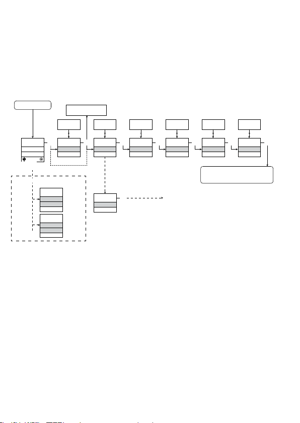
Wenn für eine Dauer von 1 Minute keine Taste betätigt wird, kehrt das Display
auf den Menüpunkt 1.0 zurück und eventuelle Änderungen in der Konfiguration
werden nicht gespeichert.
1 Wert erhöhen / nächsten Parameter wählen
2 Wert herabsetzen / vorheringen Parameter Wählen
3 Parameter speicher und nächsten Parameter wählen
Halten 3 Zurück zum vorheringen Parameter / zurück zum Menüpunkt 1.0 ohne
Speicherung von Änderungen
Power up
ON
OFF
1.0
Fehleranzeige, Beispiele
3
1.1
CA.SH
OFF
Txt 18
ON
CA.BR
Txt 19
Wenn SIL-verriegelt
direkt zu [EN.SIL]
0000
9999
1 2
0000
PASSW.
Txt 1
1.0 = Normalzustand
Zeile 1 zeigt den Status für Kanal 1
und Kanal 2.
Zeile 2 zeigt den Status für Sensor 1.
Zeile 3 zeigt den Status für Sensor 2.
FLUSSDIAGRAMM
3
NO
YES
1 2
NO
ADV.SET
Txt 2
YES
ADV.SET
Txt 2
NO
YES
1 2
3
YES
CA.SH
Txt 3
3
NO
YES
1 2
3
YES
CA.BR
Txt 4
3
DIR
INV
1 2
DIR
CH1.FUN
Txt 7
Zum Normal-
Fortsetzung auf der Seite
Flussdiagramm ADV.SET
Roter Text bedeutet
Sicherheitsparameter in
einer SIL Konfiguration.
Siehe Sicherheitshandbuch
(Safety Manual) für Details.
DIR
INV
1 2
3
DIR
CH2.FUN
Txt 7
Zustand 1.0
Zeile 4 zeigt wenn das Gerät SIL
verriegelt ist
1.1 = Nur bei Passwortschutz.
1.2 = Wenn Passwort eingegeben.
Zeile 1 Symbole:
= OK. Blinkend = Fehler
Zeile 2 und 3 Symbole:
Eingangsfrequenz > 1 Hz =
Zeile 4 Symbole:
Statischer Punkt = SIL-verriegelt
Blinkender Punkt = nicht SIL verriegelt
3
9202 - Product Version 9202-003 19
Page 22
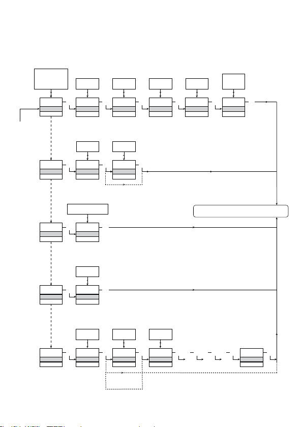
FLUSSDIAGRAMM,
ERWEITERTE EINSTELLUNGEN (ADV.SET)
DISP, PASS,
LANG, RAIL,
SIL
1 2
DISP
SETUP
Txt 6
PASS
SETUP
Txt 6/1
LANG
SETUP
Txt 6/2
RAIL
SETUP
Txt 6/3
SIL
SETUP
Txt 6/4
9
0
1 2
3
3
CONTRA
Txt 9
YES
NO
1 2
3 3
YES
EN.PASS
Txt 15
DE, DK, ES, FR,
IT, SE, UK
1 2
3
UK
LANGUA
Txt 17
YES
NO
1 2
3
YES
RAIL.ER
Txt 5
YES
NO
1 2
3
YES
EN.SIL
Txt 14
3
3
3
3
3
0000
NEW.PAS
NO
2008
NEW.PAS
NO
1.2
9
0
1 2
9
LIGHT
Txt 10
9999
0000
1 2
Txt 16
0000
9999
1 2
Txt 16
3
3
3
9
A
1 2
TAG1
TAGNO
Txt 11
TAG
A.OUT
1 2
3
TAG2
TAGNO
Txt 11
3
3
Zum Normal-Zustand 1.0
LOCK
OPEN
Bestätigung der SIL-Konfiguration
1 2
3 3 3 3 3
LOCK
CONFIG
Txt 13
. . . . . . . . . . . . . .
ALT
TAG
STAT
1 2
STAT
DISP
Txt 12
3
SIL.OK
9202 - Product Version 9202-003 20
Page 23

APPENDIX
IECEx INSTALLATION DRAWING
ATEX INSTALLATION DRAWING
FM INSTALLATION DRAWING
SAFETY MANUAL
9202 - Product Version 9202-003 21
Page 24
[
LERBAKKEN 10, 8410 RØNDE DENMARK
For safe installation of 9202B the following must be observed. The module shall only be installed by
qualified personnel who are familiar with the national and international laws, directives and standards
that apply to this area.
Year of manufacture can be taken from the first two digits in the serial number.
For Installation in Zone 2 / Division 2 the following must be observed.
The 4501 programming module is to be used solely with PR electronics modules. It is important that
the module is undamaged and has not been altered or modified in any way. Only 4501 modules free
of dust and moisture shall be installed.
IECEx Certificate KEM 06.0039 X
Marking
Standards IEC60079-15 :2005, IEC60079-11:2011, IEC60079-0: 2011
IEC60079-26: 2006
Supply terminal (31,32)
Voltage: 19.2 – 31.2 VDC
Status Relay. terminal (33,34) Zone 2 Installation
Voltage max: 125VAC / 110VDC 32VAC / 32VDC
Power max: 62,5VA / 32W 16VA / 32W
Current max: 0.5A AC / 0.3ADC 0.5A AC / 1ADC
Installation notes.
Install in pollution degree 2, overvoltage category II as defined in IEC60664-1
Do not separate connectors when energized and an explosive gas mixture is present.
Do not mount or remove modules from the Power Rail when an explosive gas mixture is present.
Disconnect power before servicing.
The wiring of unused terminals is not allowed.
In type of protection [Ex ia Da] the parameters for intrinsic safety for gas group IIB are applicable.
For installation in Zone 2, the module shall be installed in an enclosure in type of protection Ex n or
Ex e, providing a degree of protection of at least IP54. Cable entry devices and blanking elements
shall fulfill the same requirements.
For installation on Power Rail in Zone 2, only Power Rail type 9400 supplied by Power Control Unit
type 9410 (Type Examination Certificate KEMA 07ATEX0152 X) is allowed.
IECEx Installation drawing
[Ex ia Ga] IIC/IIB/IIA
Ex nA nC IIC T4 Gc
[Ex ia Da] IIIC
Ex ia Ma] I
9202QI01
Revision date:
2011-11-20
Version Revision
V4 R0
Prepared by:
PB
Page:
1/2
9202 - Product Version 9202-003 22
Page 25
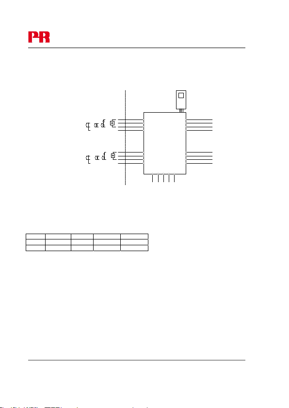
LERBAKKEN 10, 8410 RØNDE DENMARK
Hazardous area Non Hazardous area
Zone 0,1, 2, 20, 21, 22 or Zone 2
Ex input:
CH1 (terminal 41,42,43,44)
CH2 (terminal 51,52,53,54)
U
:10.6 VDC
o
I
: 12 mADC
o
P
: 32 mW
o
Lo/Ro:1150 H/
IIC IIB IIA I
Co.
2.0 F 6.0 F 18 F
Lo. 260 mH 780 mH 1000 mH 1000 mH
Terminal CH1(11,12) CH2(13,14)
Digital output: NPN output:
Voltage max. 30 VDC
Current max. 80 mA
Terminal CH1(11,12) CH2(13,14)
Relay output: Non Hazardous location Zone 2 installation
Voltage max. 250 VAC / 30 VDC 32 V AC / 30 VDC
Power max. 500 VA / 60 W 64 VA / 60 W
Current max. 2 AAC / 2 ADC 2 AAC / 2 ADC
Revision date:
2011-11-20
Switch
Switch w. Shunt
Contact Sensor
Version Revision
V4 R0
-20 ≤ Ta ≤ 60ºC
NAMUR Sensor
CH1
+
44
43
-
42
41
CH2
+
54
53
-
52
51
91 92 93 94 95
Power
Rail
4501
34
33
32
31
14
13
12
11
9202
Um: 253 V max. 400 Hz
Supply / Output:
(terminal 11,12,13,14)
(terminal 31,32,33,34)
(terminal 91,92,93,94,95)
90 µF
Prepared by:
PB
9202QI01
Page:
2/2
9202 - Product Version 9202-003 23
Page 26
LERBAKKEN 10, 8410 RØNDE DENMARK
,
Für die sichere Installation von 9202B ist Folgendes zu beachten: Das Gerät darf nur von
qualifiziertem Personal eingebaut werden, das mit den nationalen und internationalen Gesetzen,
Richtlinien und Standards auf diesem Gebiet vertraut ist.
Das Baujahr kann aus den ersten beiden Ziffern der Seriennummer ersehen werden.
Für die Installation in Zone 2 / Division 2 ist Folgendes zu beachten:
Das aufsteckbare Frontdisplay 4501 zur Programmierung ist ausschließlich mit PR electronicsGeräten zu verwenden. Es ist wichtig, dass das Display unbeschädigt ist, nicht umgebaut oder in
irgendeiner Weise verändert wurde. Das 4501 darf nur frei von Staub und Feuchtigkeit installiert
werden.
ATEX-Zertifikate KEMA 07 ATEX 0146 X
Markierung
Standards EN 60079-0 : 2009, EN 60079-11 : 2007, EN 60079-15 : 2005
EN 60079-26 : 2007, EN 61241-11 : 2006
Versorgungsklemme (31,32)
Spannung: 19,2 – 31,2 VDC
Statusrelais, Klemmen (33,34) Zone 2-Installation
Spannung max: 125 VAC / 110 VDC 32 VAC / 32 VDC
Leistung max: 62,5 VA / 32 W 16 VA / 32 W
Strom max: 0
Installationsvorskriften:
Installation in Verschmutzungsgrad 2, Überspannungskategorie II wie in der EN 60664-1 definiert.
Nicht die Anschlüsse trennen, solange ein Energie-geladenes explosives Gasgemisch vorhanden ist.
Montieren oder entfernen Sie nicht Geräte oder Baugruppen auf bzw. von der Power Rail, wenn
ein explosives Gasgemisch vorhanden ist.
Vor der Wartung die Spannungsversorgung wegschalten.
Die Verdrahtung von ungenutzten Anschlüssen ist nicht zulässig.
Bei der Schutzart [Ex ia Da] gelten die Parameter für die Eigensicherheit der Gas-Gruppe IIB.
Für Installationen in Zone 2 muss das Gerät in einem Gehäuse mit Schutzklasse Ex n oder Ex e
eingebaut sein. Das Gehäuse muss mindestens dem Schutzgrad IP54 entsprechen und die
geforderte Schlagfestigkeit aufweisen. Die Kabeleinführungen müssen ebenfalls diesen
Anforderungen entsprechen.
Für die Installation auf Power Rail in Zone 2 ist nur Power Rail Typ 9400 – in Verbindung mit dem
Power Control Unit Typ 9410 (Type Examination Certificate KEMA 07ATEX0152 X) - erlaubt.
Revision date:
2011-11-20
ATEX Installationszeichnung
II (1) G [Ex ia Ga] IIC/IIB/IIA
II 3G Ex nA nC IIC T4 Gc
I (1) D [Ex ia Da] IIIC
I (M1) [Ex ia Ma] I
5 A AC / 0,3 ADC 0,5 A AC / 1 ADC
Version Revision
V4 R0 – DE01
Prepared by:
PB
9202QA01
Page:
1/2
9202 - Product Version 9202-003 24
Page 27
9202QA01
LERBAKKEN 10, 8410 RØNDE DENMARK
Ex-Bereich Nicht-Ex-Bereich
Zone 0,1, 2, 20, 21, 22 oder Zone 2
Uo:10,6 VDC
I
: 12 mADC
o
P
: 32 mW
o
Lo/Ro:1150 H/
IIC IIB IIA I
Co.
2,0 F 6,0 F 18 F
Lo. 260 mH 780 mH 1000 mH 1000 mH
Ex-Eingang:
Kanal 1 (Klemmen 41,42,43,44)
Kanal 2 (Klemmen 51,52,53,54)
Klemmen, Kanal 1 (11,12) Kanal 2 (13,14)
Digitaler Ausgang: NPN-Ausgang:
Spannung max 30 VDC
Strom max 80 mA
Klemmen, Kanal 1 (11,12) Kanal 213,14)
Relaisausgang: Nicht explosionsgefährdeter Bereich Zone 2-Installation
Spannung max. 250 VAC / 30 VDC 32 VAC / 30 VDC
Leistung max. 500 VA / 60 W 64 VA / 60 W
Strom max. 2 AAC / 2 ADC 2 AAC / 2 ADC
Switch
Switch w. Shunt
Contact Sensor
-20 ≤ Ta ≤ 60ºC
NAMUR Sensor
CH1
+
44
43
-
42
41
CH2
+
54
53
-
52
51
90 µF
91 92 93 94 95
Power
Rail
4501
34
33
32
31
14
13
12
11
9202
Um: 253 V max. 400 Hz
Versorgung / Ausgang:
(Klemmen 11,12,13,14)
(Klemmen 31,32,33,34)
(Klemmen 91,92,93,94,95)
Revision date:
2011-11-20
Version Revision
V4 R0 – DE01
Prepared by:
PB
Page:
2/2
9202 - Product Version 9202-003 25
Page 28
(
)
LERBAKKEN 10, 8410 RØNDE DENMARK
For safe installation of 9202B the following must be observed. The module shall only be
installed by qualified personnel who are familiar with the national and international laws,
directives and standards that apply to this area.
For Installation in Zone 2 / Division 2 the following must be observed.
The 4501 programming module is to be used solely with PR electronics modules. It is
important that the module is undamaged and has not been altered or modified in any way.
Only 4501 modules free of dust and moisture shall be installed.
c-FM-us Certificate 3034430
Hazardous area
Class I/II/III, Division 1, Group A,B,C,D,E,F,G
or Class I, Zone 0/1 Group IIC, [AEx ia] IIC or
or Class I, Zone 0/1 Group IIC, [Ex ia] IIC
Simple Apparatus or
Intrinsically safe apparatus
with entity parameters:
Vmax (Ui) ≥ Vt (Uo)
Imax (Ii) ≥ It (Io)
Pi ≥ Pt(Po)
Ca(Co) ≥ C
cable + Li
La(Lo) ≥ L
U
/ Vt: 10.6 V
o
I
/ Isc: 12 mA
o
P
: 32 mW
o/Pt
Lo/Ro La/Ra: 1150 H/
Group IIC IIB IIA
Group A,B C,E,F D,G
Co/Ca
2.0
Lo./La 260 mH 780 mH 1000 mH
Terminal CH1(44,42) CH2(54,52)
Revision date:
2011-11-20
FM Installation drawing
Switch
Switch w. Shunt
Contact Sensor
cable + Ci
F 6.0 F 18 F
Version Revision
V4 R0
Non Hazardous area or
Class I, Division 2, Group A,B,C,D T4
or Class I, Zone 2 Group IIC T4
-20 ≤ Ta ≤ 60ºC
NAMUR Sensor
CH1
+
44
43
-
42
41
CH2
+
54
53
-
52
51
91 92 93 94 95
Power
Prepared by:
4501
9202
Rail
Um: 253 V max. 400 Hz
Supply / Output
(terminal 11,12,13,14)
(terminal 31,32,33,34)
terminal 91,92,93,94,95
PB
9202QF01
34
33
32
31
14
13
12
11
Page:
1/2
9202 - Product Version 9202-003 26
Page 29

9202QF01
LERBAKKEN 10, 8410 RØNDE DENMARK
Terminal (31,32)
Supply:
Voltage 19.2 – 31.2 VDC
Power max. 3 W
Terminal (33,34)
Status Relay: Non Hazardous location: Division 2 or Zone 2 installation:
Voltage max. 125 VAC / 110 VDC 32 VAC / 32VDC
Power max. 62.5 VA / 32 W 16 VA / 32 W
Current max. 0.5 AAC / 0.3 ADC 0.5 AAC / 1 ADC
Terminal CH1(11,12) CH2(13,14)
Digital output: NPN output:
Voltage max. 30 VDC
Current max. 80 mA
Terminal CH1(11,12) CH2(13,14)
Relay output: Non Hazardous location: Division 2 or Zone 2 installation:
Voltage max. 250 VAC / 30VDC 32 VAC / 30VDC
Power max. 500 VA / 60W 64 VA / 60 W
Current max. 2 AAC / 2ADC 2 AAC / 2 ADC
Installation notes:
The installation and wiring shall be in accordance with the Canadian Electrical Code for Canada and
National Electrical Code NFPA 70, Article 500 or 505 for installation in USA.
The module must be supplied from a Power Supply having double or reinforced insulation.
The use of stranded wires is not permitted for mains wiring except when wires are fitted with cable
ends.
For installation on the 9400 Power Rail the power must be supplied from Power Control Module Unit
9410.
Install in pollution degree 2, overvoltage category II.
The module must be installed in an enclosure suitable for the environment for which it is used.
For installation in Zone 2 or Division 2, the module must be installed in a suitable outer enclosure
according to the regulations in the CEC for Canada or NEC for USA.
The module is galvanically isolated and does not require grounding.
Use 60 / 75 ºC copper conductors with wire size AWG: (26-14).
Warning: Substitution of components may impair intrinsic safety and / or suitability for Div. 2 / Zone 2.
Warning: To prevent ignition of explosive atmospheres, disconnect power before servicing and do not
separate connectors when energized and an explosive gas mixture is present.
Warning: Do not mount or remove modules from the Power Rail when an explosive gas mixture is
present.
Revision date:
2011-11-20
Version Revision
V4 R0
Prepared by:
PB
Page:
2/2
9202 - Product Version 9202-003 27
Page 30

SAFETY MANUAL
PULSE ISOLATOR
9202
This safety manual is valid for the following product versions:
Version No. V5R0
9202-002
9202-003
Page 31

9202 Pulse Isolator Safety Manual
0. CONTENTS
1. Observed standards ................................................................................ 2
2. Acronyms and abbreviations ................................................................... 2
3. Purpose of the product ........................................................................... 3
4. Assumptions and restrictions for use of the product.............................. 3
4.1 Basic safety specifications ............................................................. 3
4.2 Associated equipment .................................................................... 3
4.2.1 Relay output ........................................................................ 3
4.2.2 Opto output ......................................................................... 3
4.2.3 Field device ......................................................................... 3
4.3 Failure rates .................................................................................... 3
4.4 Safe parameterisation ..................................................................... 4
4.5 Installation in hazardous areas ....................................................... 4
5. Functional specification of the safety functions...................................... 4
6. Functional specification of the non-safety functions .............................. 4
7. Safety parameters ................................................................................... 4
8. Hardware and software configuration. .................................................... 5
9. Failure category ....................................................................................... 5
10. Periodic proof test procedure ................................................................. 5
11. Procedures to repair or replace the product ........................................... 5
12. Maintenance ............................................................................................ 5
13. Documentation for routing diagram ........................................................ 6
13.1 In general ........................................................................................ 6
13.2 Further explanations ....................................................................... 6
13.2.1 Password protection ........................................................... 6
13.2.2 Cable fault information via display front 4501 .................... 6
13.4 Advanced functions ........................................................................ 6
13.4.1 Display setup ...................................................................... 7
13.4.2 Password ............................................................................ 7
13.4.3 Language ............................................................................ 7
13.4.4 Power rail ............................................................................ 7
13.4.5 Safety integrity level ............................................................ 7
14 Safe parameterisation - user responsibility ............................................. 8
14.1 Safety-related configuration parameters ........................................ 8
14.2 Verification procedure ..................................................................... 8
14.2.1 If no password is set ........................................................... 8
14.2.2 If password is set ................................................................ 9
14.3 Functional test ................................................................................ 9
15 Fault reaction and restart condition ........................................................ 9
16 User interface .......................................................................................... 10
16.1 Scrolling help texts in display line 3 ............................................... 10
16.2 Routing diagram .............................................................................. 11
16.3 Routing diagram - Advanced settings (ADV.SET)........................... 12
17. Connections diagram ............................................................................. 13
Version No. V5R0 1
Page 32

Safety Manual 9202 Pulse Isolator
1. Observed standards
Standard Description
IEC 61508
IEC 61508-
2:2000
IEC 61508-
3:1998
IEC 61326-
3-1:2008
Functional Safety of electrical / electronic / programmable
electronic safety-related systems
Part 2: Requirements for electrical / electronic / programmable
electronic safety-related systems
Part 3: Software requirements
Immunity requirements for safety-related systems
2. Acronyms and abbreviations
Acronym /
Abbreviation
Element
PFD
PFH
SFF
SIF
SIL
Designation Description
Probability of
Failure on Demand
Probability of dan-
gerous Failure per
Hour
Safe Failure
Fraction
Safety Integrity
Function
Safety Integrity
Level
Term defined by IEC 61508 as “part of a
subsystem comprising a single component
or any group of components that performs
one or more element safety functions”
This is the likelihood of dangerous safety
function failures occurring on demand.
The term “Probability” is misleading, as IEC
61508 defines a Rate.
Safe Failure Fraction summarises the
fraction of failures which lead to a safe
state and the fraction of failures which will
be detected by diagnostic measures and
lead to a defined safety action.
Function that provides fault detection (to
ensure the necessary safety integrity for the
safety functions)
The international standard IEC 61508
specifies four discrete safety integrity levels
(SIL 1 to SIL 4). Each level corresponds to
a specific probability range regarding the
failure of a safety function.
2 Version No. V5R0
Page 33

9202 Pulse Isolator Safety Manual
3. Purpose of the product
Pulse isolator for transmission of signals to the safe area from NAMUR sensors
and mechanical switches installed in the hazardous area.
The module can be mounted in the safe area and in zone 2 / div. 2 and receive
signals from zone 0, 1, 2, 20, 21 and 22 / Class I/II/III, Div. 1, Gr. A-G.
Error events, including cable breakage, are monitored and signalled via the
individual status relay and/or a collective electronic signal via the power rail.
The 9202 has been designed, developed and certified for use in SIL 2 applications
according to the requirements of IEC 61508.
4. Assumptions and restrictions for use of the product
4.1 Basic safety specifications
Operational temperature range ............ -20...+60°C
Storage temperature range .................. -20...+85°C
Power supply type, min. ....................... Double or reinforced
Supply voltage ...................................... 19.2...31.2 VDC
Output pulse length, min. ..................... 40 ms
Mounting area ....................................... Zone 2 / Division 2 or safe area
Mounting environment .......................... Pollution degree 2 or better
4.2 Associated equipment
4.2.1 Relay output
The relay output shall only be connected to equiment which has
a current limiting function of 2 A.
4.2.2 Opto output
The opto output signals are fed to SIL 2 compliant inputs of a
safety PLC specified to receive a frequency of 5 kHz and a pulse
length down to 40 microseconds or the field device signal pulse
length minus 60 microseconds.
4.2.3 Field device
The field device must provide a minimum pulse length of 100
microseconds.
4.3 Failure rates
The basic failure rates from the Siemens standard SN 29500 are used
as the failure rate database.
Failure rates are constant, wear-out mechanisms are not included.
External power supply failure rates are not included.
Version No. V5R0 3
Page 34

Safety Manual 9202 Pulse Isolator
4.4 Safe parameterisation
The user is responsible for verifying the correctness of the configuration
parameters. (See section 14 Safe parameterisation - user responsibility).
Manual override may not be used for safety applications.
4.5 Installation in hazardous areas
The IECex Installation drawing, ATEX Installation drawing and FM
Installation drawing shall be followed if the products are installed in
hazardous areas.
5. Functional specification of the safety functions
Pulse isolator as well as supply of NAMUR sensors and mechanical switches with
cable error detection installed in the hazardous area. Cable error detection only
works with NAMUR sensors or with the use of external resistors Rs and Rp. See
connections diagram at page 13 (switch, cable fault) .
6. Functional specification of the non-safety functions
The status relay (terminal 33 and 34), error signal on power rail (terminal 91) and
LED outputs are not suitable for use in any Safety Instrumented Function.
7. Safety parameters
Probability of dangerous Failure per Hour (PFH) 4.66E-8 3.62E-8
Probability of failure on demand (PFD) -
1 year proof test interval
Proof test interval (10% of loop PFD) 4 years 5 years
Safe Failure Fraction 90% 91%
Demand response time, opto output
Demand response time, relay output
Demand mode High
Demand rate 1000 s
Mean Time To Repair (MTTR) 8 hours
Diagnostic test interval 10 seconds
Hardware Fault Tolerance (HFT) 0
Component Type B
SIL capability SIL 2
Description of the “Safe State”, opto output High impedance
Description of the “Safe State”, relay output De-energised
Relay lifetime (Note
2
) 100 000 times
Relay Opto
1
, Note2
Note
2.04E-4 1.58E-4
<125
µs
<10 m
s
4 Version No. V5R0
Page 35

9202 Pulse Isolator Safety Manual
Note1: The 9202 contains no lifetime limiting components, therefore the PFH
figures are valid for up to 12 years, according to IEC 61508.
2
: The maximum frequency for Pulse Isolator 9202 with relay output is 20 Hz.
Note
The user must calculate the product lifetime with regard to the relay lifetime.
8. Hardware and software configuration.
All configurations of software and hardware versions are fixed from factory, and
cannot be changed by end-user or reseller.
This manual only covers products labelled with the product version (or range of
versions) specified on the front page.
9. Failure category
Failure category
Fail Safe Detected 0.000E+00 0.000E+00
Fail Safe Undetected 2.897E-07 2.755E-07
Fail Dangerous Detected 1.303E-07 1.356E-07
Fail Dangerous Undetected 4.658E-08 3.618E-08
Failure rates (1/h)
Relay Opto
10. Periodic proof test procedure
Step Action
1 Bypass the safety PLC or take other appropriate action to avoid a false trip
Connect a simulator identical to the input setup
2
Perform an ON / OFF signal for each channel
3
Observe whether the output channel acts as expected
4
Restore the input terminals to full operation
5
Remove the bypass from the safety PLC or otherwise restore normal operation
6
This test will detect approximately 95% of possible “du” (dangerous undetected)
failures in the pulse isolator. The proof test is equivalent to the functional test.
11. Procedures to repair or replace the product
Any failures that are detected and that compromise functional safety should be
reported to the sales department at PR electronics A/S.
Repair of the module and replacement of circuit breakers must be done by PR
electronics A/S only.
12. Maintenance
No maintenance required.
Version No. V5R0 5
Page 36

Safety Manual 9202 Pulse Isolator
13. Documentation for routing diagram
The routing diagram is shown in section 16.2.
13.1 In general
When configuring the 9202, you will be guided through all parameters
and you can choose the settings which fit the application. For each
menu there is a scrolling help text which is automatically shown in line
3 on the display.
Configuration is carried out by use of the 3 function keys:
1 will increase the numerical value or choose the next parameter
2will decrease the numerical value or choose the previous parameter
3will save the chosen value and proceed to the next menu
When configuration is completed, the display will return to the default
state 1.0.
Pressing and holding
default state (1.0) without saving the changed values or parameters.
If no key is activated for 1 minute, the display will return to the default
state (1.0) without saving the changed values or parameters.
13.2 Further explanations
13.2.1 Password protection
Access to the configuration can be blocked by assigning
a password. The password is saved in the module in order
to ensure a high degree of protection against unauthorised
modifications to the configuration. Default password 2008
allows access to all configuration menus.
Password protection is mandatory in SIL applications.
13.2.2 Cable fault information via display front 4501
Cable fault (see limits in the table) is displayed as CA.BR
(cable break) or CA.SH (cable short-circuited). Cable fault is
shown independently for each channel but the configuration is
common for both channels. In case of cable fault the backlight
flashes. This can be reset by pressing the
cable fault has been remedied, the module will return to normal
operation.
13.4 Advanced functions
The unit gives access to a number of advanced functions which can be
reached by answering “Yes” to the point “adv.set”.
3 will return to the previous menu or return to the
3 key. When the
6 Version No. V5R0
Page 37

9202 Pulse Isolator Safety Manual
13.4.1 Display setup
Here you can adjust the brightness contrast and the backlight.
Setup of tag numbers with 5 alphanumerics. Selection of
functional readout in line 2 and 3 of the display - choose between
readout of digital output or tag no. When selecting ”ALT” the
readout toggles between digital output and tag no.
13.4.2 Password
Here you can choose a password between 0000 and 9999 in
order to protect the unit against unauthorised modifications
to the configuration. The unit is delivered default without
password.
13.4.3 Language
In the menu ”LANG” you can choose between 7 different
language versions of help texts that will appear in the menu. You
can choose between UK, DE, FR, IT, ES, SE and DK.
13.4.4 Power rail
In the menu ”RAIL” you can choose if errors in the module are
transmitted to the central surveillance in the PR 9410 power
control unit.
13.4.5 Safety integrity level
See Safe parameterisation - user responsibility
Version No. V5R0 7
Page 38

Safety Manual 9202 Pulse Isolator
14 Safe parameterisation - user responsibility
14.1 Safety-related configuration parameters
Parameters Value Description
CH1.FUN DIR / INV Direct / inverted channel function
CH2.FUN. DIR / INV Direct / inverted channel function
PASSW 0 - 9999 New password
The above safety-related configuration parameters are marked in red
text in the routing diagrams and must be verified by the user in a SILconfiguration.
14.2 Verification procedure
The verification is done using the display / programming front PR 4501
by following the procedure described below.
14.2.1 If no password is set
Action Display shows
1 Press OK ADV.SET
2 Set (ADV.SET) to Yes and press OK DISP SETUP
3 Step down to (SIL SETUP) and press OK EN.SIL
4 Set (EN SIL) to YES and press OK NEW.PASS
5 Set password to a number between 0 and
9999 and press OK
(At this time the module starts operating
in SIL mode with the entered configuration
parameters!)
6 Verify Channel 1 function and press OK CH1.FUN
7 Verify Channel 2 function and press OK CH2:FUN
8 Verify password and press OK PASSW
9 Verify SIL and press OK
* Open is shown briefly in the display.
VerifyOPEN
”briefly”
LOCK*
8 Version No. V5R0
Page 39

9202 Pulse Isolator Safety Manual
14.2.2 If password is set
Action Display shows
1 Press OK PASSW
2 Enter password and press OK ADV.SET
3 Set (ADV.SET) to Yes and press OK DISP SETUP
4 Step down to (SIL SETUP) and press OK EN.SIL
5 Set (EN SIL) to YES and press OK
(At this time the module starts operating
in SIL mode with the entered configuration
parameters!)
6 Verify Channel 1 function and press OK CH1.FUN
7 Verify Channel 2 function and press OK CH2:FUN
8 Verify password and press OK PASSW
9 Verify SIL and press OK
VerifyOPEN
”briefly”
LOCK*
* Open is shown briefly in the display
14.3 Functional test
The user is responsible to make a functional test after verification of
safety parameters. The procedure for periodic proof test described in
section 10 shall be used.
15 Fault reaction and restart condition
When the 9202 detects a fault the output will go to Safe State, in which the opto
output will go to “high impedance” or the relay output will go to “de-energised”.
If the fault is application-specific (cable error detection) the 9202 will restart when
the fault has been corrected.
For device faults there are 2 ways of bringing the module out of Safe State.
1. Power cycle the module.
2. Bring the module out of SIL mode (choose “NO” in the menu point ”EN.SIL”),
and set it back to SIL mode again (choose “YES” in the menu point “EN.SIL” and
verify the configuration).
Version No. V5R0 9
Page 40

Safety Manual 9202 Pulse Isolator
16 User interface
16.1 Scrolling help texts in display line 3
Set correct password [ PASS ]
[01]
Enter advanced setup [ ADV.SET ]
[02]
Enable cable short circuit error indication [ CA.SH ]
[03]
Enable cable breakage error indication? [ CA.BR ]
[04]
Enable rail status signal output? [ RAIL.ER ]
[05]
Enter language setup [ SETUP ]
[06]
Enter password setup [ SETUP ]
[6/1]
Enter display setup [ SETUP ]
[6/2]
Enter rail setup [ SETUP ]
[6/3]
Enter SIL setup [ SETUP ]
[6/4]
Select direct channel function [ CH1.FUN ] [CH2.FUN ]
[07]
Select inverted channel function [ CH1.FUN ] [ CH2.FUN ]
Adjust LCD contrast [ CONTRA ]
[09]
Adjust LCD backlight [ LIGHT ]
[10]
Write a 5-character channel [ ’TAGON ] [ ”TAGON ]
[11]
Show output state in display [ DISP ]
[12]
Show TAG in display
Alternate shown information in display
Configuration SIL status (Open / Locked) [ CONFIG ]
[13]
Enable SIL configuration lock [ EN.SIL ]
[14]
Enable password protection [ EN.PASS ]
[15]
Set new password [ NEW.PAS ]
[16]
Select language [ LANGUA ]
[17]
Cable short circuit [ 1CA.SH ] [ 2OFF ]
[18]
Cable breakage [ 1ON ] [ 2CA.BR ]
[19
10 Version No. V5R0
Page 41
9202 Pulse Isolator Safety Manual
16.2 Routing diagram
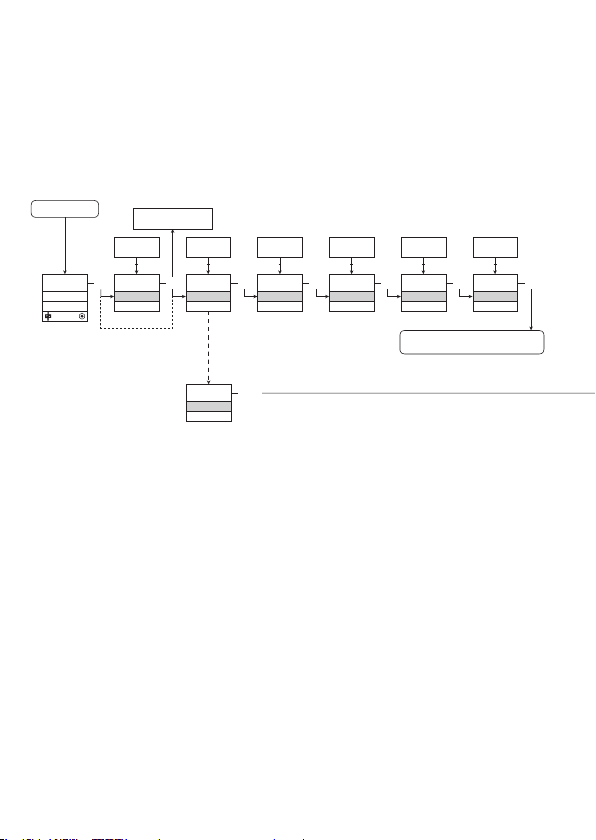
If no key is activated for 1 minute, the display will return to the default
state 1.0 without saving configuration changes.
1 Increase value / choose next parameter
2 Decrease value / choose previous parameter
3 Save the chosen value and proceed to the next menu
Hold 3 Back to previous menu / return to menu 1.0 without saving
Power up
ON
OFF
1.0
3
0000
1.1
PASSW.
Txt 1
If SIL-locked
directly to [EN.SIL]
0000
9999
1 2
3
NO
YES
1 2
NO
ADV.SET
Txt 2
YES
ADV.SET
Txt 2
NO
YES
1 2
3
YES
CA.SH
Txt 3
3
1.0 = Default state
Line 1 shows status for channel 1 and
channel 2.
Line 2 shows status for sensor 1.
Line 3 shows status for sensor 2.
Line 4 indicates whether the module
is SIL-locked.
1.1 = Only if password-protected
1.2 = If password has been set.
Line 1 symbols:
= OK. Flashing = error
Line 2 and 3 symbols:
Input frequency > 1 Hz =
Line 4 symbols:
Static dot = SIL-locked
Flashing dot = not SIL-locked
NO
YES
1 2
3
YES
CA.BR
Txt 4
3
DIR
INV
1 2
DIR
CH1.FUN
Txt 7
3
To default state 1.0
Continued on the page
Routing diagram ADV.SET
DIR
INV
1 2
DIR
CH2.FUN
Txt 7
3
Version No. V5R0 11
Page 42
Safety Manual 9202 Pulse Isolator
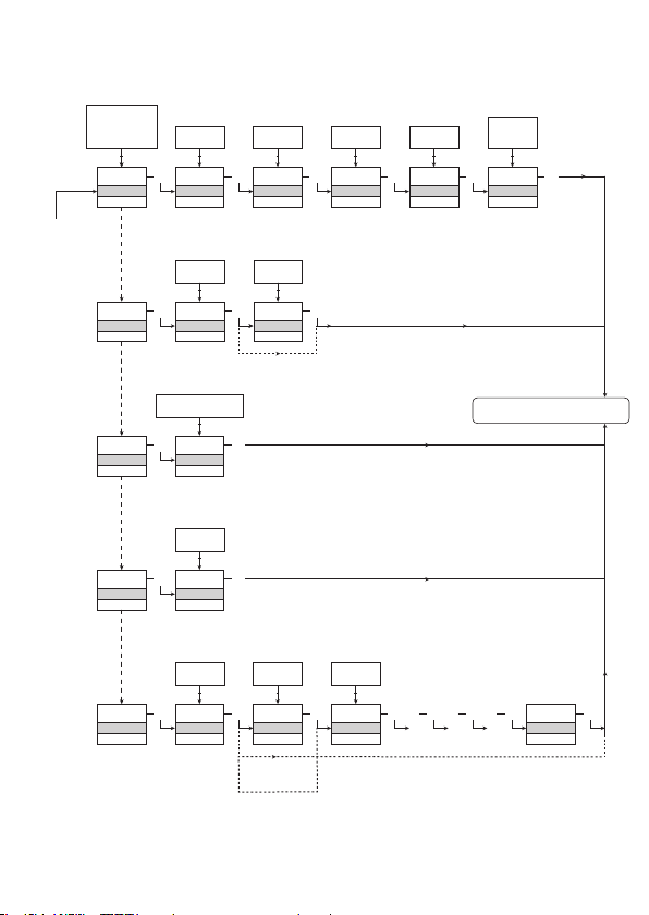
16.3 Routing diagram - Advanced settings (ADV.SET)
DISP, PASS,
LANG, RAIL,
SIL
1 2
DISP
SETUP
Txt 6
PASS
SETUP
Txt 6/1
LANG
SETUP
Txt 6/2
RAIL
SETUP
Txt 6/3
SIL
SETUP
Txt 6/4
9
0
1 2
3
3
CONTRA
Txt 9
YES
NO
1 2
3 3
YES
EN.PASS
Txt 15
DE, DK, ES, FR,
IT, SE, UK
1 2
3
UK
LANGUA
Txt 17
YES
NO
1 2
3
YES
RAIL.ER
Txt 5
YES
NO
1 2
3
YES
EN.SIL
Txt 14
3
3
3
3
3
NO
NO
1.2
9
0
1 2
9
LIGHT
Txt 10
9999
0000
1 2
0000
NEW.PAS
Txt 16
0000
9999
1 2
2008
NEW.PAS
Txt 16
3
3
3
9
A
1 2
TAG1
TAGNO
Txt 11
LOCK
OPEN
1 2
LOCK
CONFIG
Txt 13
TAG
A.OUT
1 2
3
TAG2
TAGNO
Txt 11
3
3
Verification of SIL configuration
3 3 3 3 3
. . . . . . . . . . . . . .
ALT
TAG
STAT
1 2
3
STAT
DISP
Txt 12
To default state 1.0
SIL.OK
12 Version No. V5R0
Page 43
9202 Pulse Isolator Safety Manual
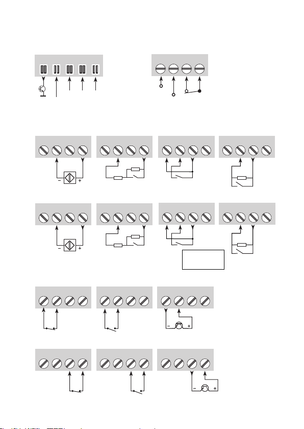
17. Connections diagram
Power rail
connections
91 92 93 94 95
Supply and
status relay
31 32 33 34
Error
NC = no connection
Channel 1Channel 2Channel 1
Gnd.
+24 V
NAMUR sensor,
cable fault
41 42 43 44
NAMUR sensor,
cable fault
51 52 53 54
NCNC
Switch,
cable fault
41 42 43 44
R
s
Switch,
cable fault
51 52 53 54
R
s
Inputs:
R
p
R
p
Outputs:
Relay, N.C. Opto, NPN
11 12 13 14
Relay, N.C. Opto, NPNRelay, N.O.
11 12 13 14
Relay, N.O.
11 12 13 14
11 12 13 14
Gnd.
N.C.
+24 V
Switch,
no cable fault
Switch,
no cable fault
41 42 43 44 41 42 43 44
R
p
Switch,
no cable fault
Switch,
no cable fault
51 52 53 54 51 52 53 54
R
p
Rp = 15 kΩ
Rs = 750 Ω
11 12 13 14
11 12 13 14
Channel 2
Version No. V5R0 13
Page 44
Displays
Programmable displays with a wide
selection of inputs and outputs for display of temperature,
volume and weight, etc. Feature linearisation, scaling,
and difference measurement functions for programming
via PReset software.
Ex interfaces
signals as well as HART
Interfaces for analogue and digital
®
signals between sensors / I/P
converters / frequency signals and control systems in Ex
zone 0, 1 & 2 and for some modules in zone 20, 21 & 22.
Isolation
digital signals as well as HART
Galvanic isolators for analogue and
®
signals. A wide product
range with both loop-powered and universal isolators
featuring linearisation, inversion, and scaling of output
signals.
Temperature
A wide selection of transmitters for DIN
form B mounting and DIN rail modules with analogue
and digital bus communication ranging from applicationspecic to universal transmitters.
Universal
PC or front programmable modules with
universal options for input, output and supply. This range
offers a number of advanced features such as process
calibration, linearisation and auto-diagnosis.
Page 45

www.prelectronics.fr
[email protected]
www.prelectronics.de
[email protected]
www.prelectronics.es
[email protected]
www.prelectronics.it
[email protected]
www.prelectronics.se
[email protected]
www.prelectronics.co.uk
[email protected]
www.prelectronics.com
[email protected]
www.prelectronics.cn
[email protected]
Head ofce
Denmark www.prelectronics.com
DK-8410 Rønde fax +45 86 37 30 85
 Loading...