

Page 1
PENDING
9 1 1 6
U n i v e r s a l
c o n v e r t e r
N o . 9 1 1 6 V 1 0 1 - I N ( 1 0 3 1 )
P r o d u c t v e r s i o n : 9 1 1 6 - 0 0 1
S I G N A L S T H E B E S T
PENDING
DK
UK
FR
DE
Side 1
Page 33
Page 65
Seite 97
MTS
Messtechnik
Schaffhausen GmbH
CH
-
8260 Stein am Rhein
Telefon +
4152-6725000
Messen Prüfen Automatisieren www.mts.ch
Page 2

PR electronics A/S tilbyder et bredt program af analoge og digitale
signalbehandlingsmoduler til industriel automation. Programmet
består af Isolatorer, Displays, Ex-barrierer, Temperaturtransmittere,
Universaltransmittere mfl. Vi har modulerne, du kan stole på i selv
barske miljøer med elektrisk støj, vibrationer og temperaturudsving,
og alle produkter opfylder de strengeste internationale standarder.
Vores motto »Signals the Best« er indbegrebet af denne filosofi –
og din garanti for kvalitet.
PR electronics A/S offers a wide range of analogue and digital
signal conditioning modules for industrial automation. The product
range includes Isolators, Displays, Ex Interfaces, Temperature
Transmitters, and Universal Modules. You can trust our products
in the most extreme environments with electrical noise, vibrations
and temperature fluctuations, and all products comply with the
most exacting international standards. »Signals the Best« is the
epitome of our philosophy – and your guarantee for quality.
PR electronics A/S offre une large gamme de produits pour le
traite ment des signaux analogiques et numériques dans tous
les domaines industriels. La gamme de produits s’étend des
transmetteurs de température aux afficheurs, des isolateurs aux
interfaces SI, jusqu’aux modules universels. Vous pouvez compter
sur nos produits même dans les conditions d’utilisation sévères,
p.ex. bruit électrique, vibrations et fluctuations de température.
Tous nos produits sont conformes aux normes internationales les
plus strictes. Notre devise »SIGNALS the BEST« c’est notre ligne
de conduite - et pour vous l’assurance de la meilleure qualité.
PR electronics A/S verfügt über ein breites Produktprogramm
an analogen und digitalen Signalverarbeitungsmodule für die industrielle Automatisierung. Dieses Programm umfasst Displays,
Temperaturtransmitter, Ex- und galvanische Signaltrenner, und
Universalgeräte. Sie können unsere Geräte auch unter extremen
Einsatzbedingungen wie elektrisches Rauschen, Erschütterungen
und Temperaturschwingungen vertrauen, und alle Produkte von
PR electronics werden in Überein stimmung mit den strengsten
internationalen Normen produziert. »Signals the Best« ist Ihre
Garantie für Qualität!
DK
UK
FR
DE
Page 3

9116 - Product Version 9116-001 1
UNIVERSALKONVERTER
9116
INDHOLDSFORTEGNELSE
Advarsel .......................................................................................... 2
Signaturforklaring ........................................................................... 2
Sikkerhedsregler ............................................................................. 2
Afmontering af system 9000 .......................................................... 4
EF-Overensstemmelseserklæring .................................................. 5
Avancerede features....................................................................... 6
Anvendelse ..................................................................................... 6
Teknisk karakteristik ....................................................................... 6
Applikationer .................................................................................. 7
PR 4501 Display- / programmeringsfront ...................................... 8
Bestillingsnumre ............................................................................. 9
Elektriske specifikationer................................................................ 9
Konfigurering af følerfejlscheck ...................................................... 13
Displayvisning på 4501 af:
Indgangssignal uden for område ............................................... 14
Følerfejlsdetektering................................................................... 14
Hardwarefejl ............................................................................... 15
Tilslutninger .................................................................................... 17
Blokdiagram ................................................................................... 18
Visning af signal- og kabelfejl uden displayfront ........................... 19
Programmering / betjening af trykknapper .................................... 20
Rutediagram ................................................................................... 25
Rutediagram, Avancerede indstillinger (ADV.SET) ......................... 27
Rullende hjælpetekster i displaylinie 3 ........................................... 28
Grafisk afbildning af relæfunktionen vindue................................... 30
Grafisk afbildning af relæfunktionen setpunkt ............................... 31
Appendix ........................................................................................ 128
IECEx Installation Drawing......................................................... 129
ATEX Installation Drawings, UK, FR, DE, DK ............................ 133
FM Installation Drawing ............................................................. 149
Safety manual ............................................................................ 153
Page 4
2 9116 - Product Version 9116-001
SIGNATURFORKLARING
Trekant med udråbstegn: Læs manualen før installation og idriftsættelse
af modulet for at undgå hændelser, der kan føre til skade på personer
eller materiel.
CE-mærket er det synlige tegn på modulets overensstemmelse med
EU-direktivernes krav.
Dobbelt isolation er symbolet for, at modulet overholder ekstra krav til
isolation.
Ex - Modulet er godkendt efter ATEX-direktivet til brug i forbindelse
med installationer i eksplosionsfarlige områder. Se installationstegning i
appendiks.
SIKKERHEDSREGLER
DEFINITIONER
Farlige spændinger er defineret som områderne: 75...1500 Volt DC og
50...1000 Volt AC.
Teknikere er kvalificerede personer, som er uddannet eller oplært til at kunne
udføre installation, betjening eller evt. fejlfinding både teknisk og sikkerhedsmæssigt forsvarligt.
Operatører er personer, som under normal drift med produktet skal indstille og
betjene produktets trykknapper eller potentiometre, og som er gjort bekendt
med indholdet af denne manual.
ADVARSEL
Følgende operationer bør kun udføres på modulet i spændingsløs tilstand og under ESD-sikre forhold:
Installation, ledningsmontage og -demontage.
Fejlfinding på modulet.
Reparation af modulet og udskiftning af sikringer må kun
foretages af PR electronics A/S.
ADVARSEL
Modulets frontplade må ikke åbnes, da dette vil medføre skade
på stikforbindelsen til display- / programmeringsfronten PR
4501. Modulet indeholder ingen DIP-switche eller jumpere.
Page 5

9116 - Product Version 9116-001 3
MODTAGELSE OG UDPAKNING
Udpak modulet uden at beskadige det. Kontrollér ved modtagelsen, at modultypen svarer til den bestilte. Indpakningen bør følge modulet, indtil dette er monteret på blivende plads.
MILJØFORHOLD
Undgå direkte sollys, kraftigt støv eller varme, mekaniske rystelser og stød, og
udsæt ikke modulet for regn eller kraftig fugt. Om nødvendigt skal opvarmning,
ud over de opgivne grænser for omgivelsestemperatur, forhindres ved hjælp af
ventilation.
Modulet skal installeres i forureningsgrad 2 eller bedre.
Modulet er designet til at være sikkert mindst op til en højde af 2000 m.
INSTALLATION
Modulet må kun tilsluttes af teknikere, som er bekendte med de tekniske
udtryk, advarsler og instruktioner i manualen, og som vil følge disse.
Hvis der er tvivl om modulets rette håndtering, skal der rettes henvendelse til
den lokale forhandler eller alternativt direkte til:
PR electronics A/S, Lerbakken 10, 8410 Rønde,
Danmark, tlf: +45 86 37 26 77.
Det er ikke tilladt at benytte flerkoret ledning ved tilslutning af forsyningsspænding med mindre ledningsenderne er forsynet med ledningstyller.
Beskrivelse af indgang / udgang og forsyningsforbindelser findes på blokdiagrammet og sideskiltet.
Modulet er forsynet med skrueterminaler og skal forsynes fra en dobbeltisoleret/
forstærket isoleret spændingsforsyning. En afbryder placeres let tilgængeligt og
tæt ved modulet. Afbryderen skal mærkes således, at der ikke er tvivl om, at
den afbryder spændingen til modulet.
Ved installation på Power Rail 9400 bliver forsyningsspændingen leveret af
Power Control Unit type 9410.
Produktionsår fremgår af de to første cifre i serienummeret.
KALIBRERING OG JUSTERING
Under kalibrering og justering skal måling og tilslutning af eksterne spændinger
udføres i henhold til denne manual, og teknikeren skal benytte sikkerhedsmæssigt korrekte værktøjer og instrumenter.
Page 6
4 9116 - Product Version 9116-001
BETJENING UNDER NORMAL DRIFT
Operatører må kun indstille eller betjene modulerne, når disse er fast installeret
på forsvarlig måde i tavler el. lignende, så betjeningen ikke medfører fare for liv
eller materiel. Dvs., at der ikke er berøringsfare, og at modulet er placeret, så
det er let at betjene.
RENGØRING
Modulet må, i spændingsløs tilstand, rengøres med en klud let fugtet med
destilleret vand.
ANSVAR
I det omfang instruktionerne i denne manual ikke er nøje overholdt, vil kunden
ikke kunne rette noget krav, som ellers måtte eksistere i henhold til den indgåede salgsaftale, mod PR electronics A/S.
AFMONTERING AF SYSTEM 9000
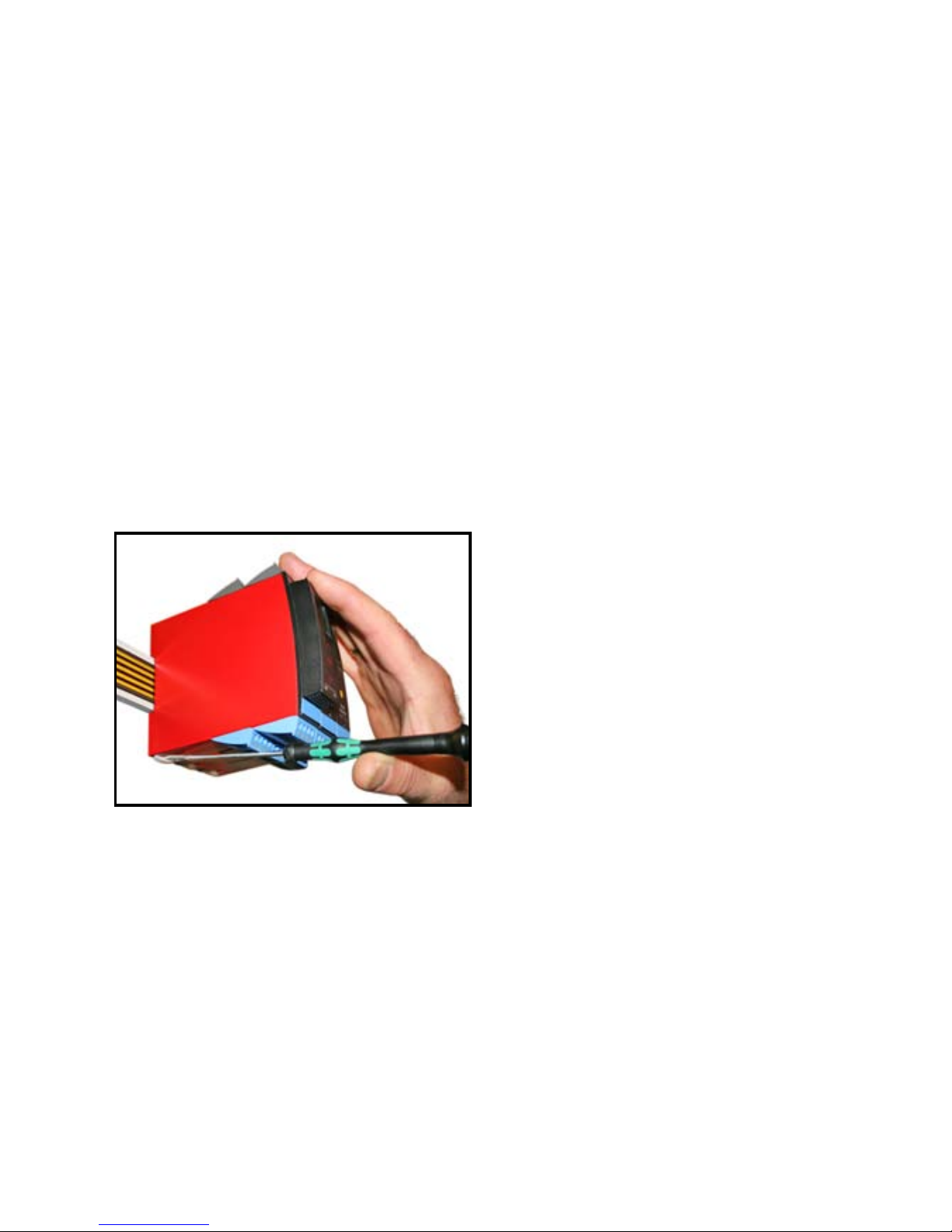
Billede 1:
Modulet frigøres fra DIN-skinnen ved
at løfte i den nederste lås.
Page 7

9116 - Product Version 9116-001 5
EF-OVERENSSTEMMELSESERKLÆRING
Som producent erklærer
PR electronics A/S
Lerbakken 10
DK-8410 Rønde
hermed at følgende produkt:
Type: 9116
Navn: Universalkonverter
er i overensstemmelse med følgende direktiver og standarder:
EMC-direktivet 2004/108/EF og senere tilføjelser
EN 61326-1 : 2006
For specifikation af det acceptable EMC-niveau henvises til modulets
elektriske specifikationer.
Lavspændingsdirektivet 2006/95/EF og senere tilføjelser
EN 61010-1 : 2001
ATEX-direktivet 94/9/EF og senere tilføjelser
EN 61241-0 : 2006, EN 61241-11 : 2006, EN 60079-0 : 2006,
EN 60079-11 : 2007, EN 60079-15 : 2005, EN 60079-26 : 2007
ATEX certificate: KEMA 07ATEX0149 X
Bemyndiget organ:
KEMA Quality B.V. (0344)
Utrechtseweg 310, 6812 AR Arnhem
P.O. Box 5185, 6802 ED Arnhem
The Netherlands
Rønde, 15. januar 2010 Kim Rasmussen
Producentens underskrift
Page 8

6 9116 - Product Version 9116-001
UNIVERSALKONVERTER
9116
• Indgang for RTD, TC, Ohm, potentiometer, mA og V
• Forsyning for 2-trådstransmittere
• Aktiv / passiv mA-udgang og relæudgang
• Kan forsynes separat eller installeres på power rail,
PR type 9400
• SIL 2-certificeret via Full Assessment
Avancerede features
• Konfiguration og monitorering via aftagelig displayfront (PR 4501); proceskalibrering, signal- og relæsimulering.
• Avanceret relæ-opsætning; f.eks. setpunkt, vindue, forsinkelse, følerfejlsindikrering og forsyningsovervågning.
• Kopiering af opsætningen fra et modul til andre af samme type via displayfronten.
• Reducerede Uo Ex-data < 8,3 V for aktive indgangssignaler.
• TC-indgange med intern eller ekstern CJC for højere nøjagtighed.
• 9116 detekterer automatisk, om modulet skal levere et aktivt eller et passivt
strømsignal.
Anvendelse
• 9116 kan monteres i sikkert område samt i zone 2 / division 2 og modtage
signaler fra zone 0, 1, 2, 20, 21 og 22 / Class I/II/III, Div. 1, Gr. A-G.
• Konvertering og skalering af temperatur-, spændings-, potentiometer- og
lineære modstandssignaler.
• Spændingsforsyning og signalisolator for 2-trådstransmittere.
• Overvågning af fejlsituationer og kabelbrud via det individuelle statusrelæ og/
eller kollektivt elektronisk signal via power rail.
• 9116 er konstrueret, udviklet og certificeret til brug i SIL 2-installationer iht.
kravene i IEC 61508.
Teknisk karakteristik
• 1 grøn og 1 rød LED i front indikerer normal drift og funktionsfejl. 1 gul LED
indikerer relæstatus.
• 2,6 kVAC galvanisk isolation mellem indgang / udgang / forsyning.
Page 9
*
+
-
mA
mA
+
44
43
42
41
12
11
14
13
+
+
+
-
Tx
54
53
52
51
31
32
33
34
9116 - Product Version 9116-001 7
Zone 0, 1, 2,
20, 21, 22 /
Cl. I/II/III, div. 1
gr. A-G Zone 2 / Cl. 1, div. 2, gr. A-D eller sikkert område
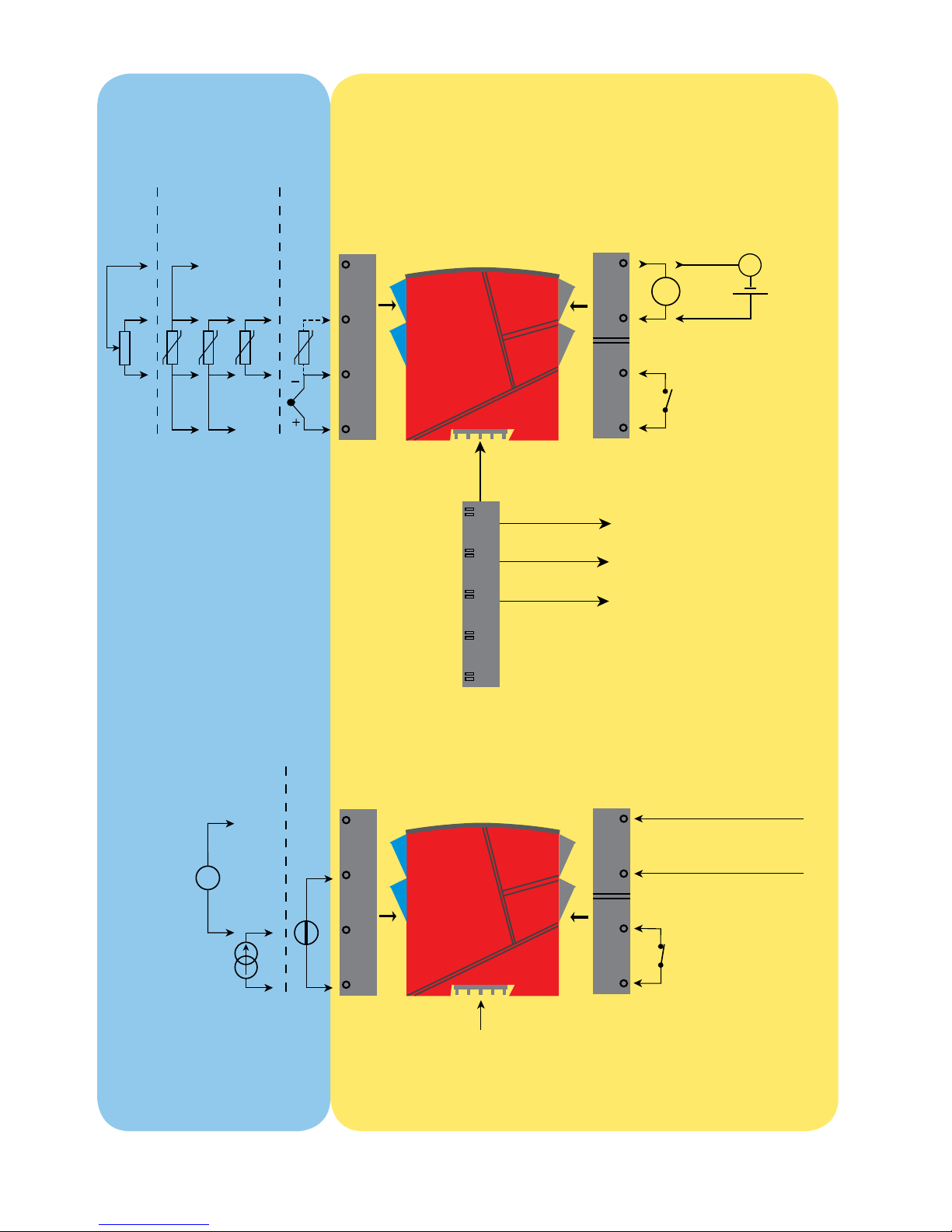
APPLIKATIONER
Indgangssignaler:
Poten-
tiometer
TC
RTD og lin. R
Forbindelse, ledere
Analog, 0/4...20 mA og relæ
Relæ
Relæ
N.O.
Rail, +24 VDC
Rail, Gnd.
Power rail
Statusrelæ-signal
Udgangssignaler:
*Bestilles særskilt:
CJC-klemme 5910Ex
Strøm
Spæn-
ding
Modulstatus
Modulstatus
Gnd.
Forsyning +19,2...31,2 VDC
N.C.
Forsyningsspændinger:
Forsyning via
power rail
Ingen forbindelse
Ingen forbindelse
Page 10

8 9116 - Product Version 9116-001
PR 4501 DISPLAY- / PROGRAMMERINGSFRONT
Funktionalitet
Den enkle menustruktur og de forklarende hjælpe tekster leder
dig automatisk gennem opsætningen, og gør produktet meget
enkelt at anvende. Se beskrivelse af funktioner og opsætningsmuligheder under afsnittet ”Progammering / betjening af trykknapper”.
Anvendelse
• Kommunikationsinterface til ændring af driftsparametre i 9116.
• Kan flyttes fra en 9116 til en anden 9116 og downloade opsætningen fra det
første module til andre af samme type.
• Som fastmonteret display til visualisering af procesdata og status.
Teknisk karakteristik
• Fire liniers LCD-display, linie 1 (5,57 mm høj) viser indgangsstatus, linie 2
(3,33 mm høj) skifter mellem indgangsværdi og TAG-nr., linie 3 (3,33 mm høj)
viser udgangsværdi og enheder - UNIT, og linie 4 viser status for relæ og
kommunikation samt om modulet er SIL-låst. Statisk prik = SIL-låst og blinkende prik = ikke SIL-låst.
• Programmeringsadgang kan forhindres ved indkodning af et password.
Passwordet gemmes i 9116, så sikkerheden mod uønskede ændringer er så
høj som muligt.
Montage / installation
• Klikkes på fronten af 9116.
Page 11

9116 - Product Version 9116-001 9
Bestillingsnumre
9116B1 = Universalkonverter - Uo 28 VDC (max. loop-spænding)
9116B2 = Universalkonverter - Uo 22 VDC (max. loop-spænding)
4501 = Display- / programmeringsfront
5910Ex = CJC-klemme
9400 = Power rail
Elektriske specifikationer
Specifikationsområde .................................. -20...+60°C
Lagringstemperatur ..................................... -20...+85°C
Fælles specifikationer:
Forsyningsspænding, DC ............................ 19,2...31,2 VDC
Max. forbrug ................................................ ≤ 3,5 W
Sikring ......................................................... 1,25 A T / 250 VAC
Isolationsspænding, test / drift ................... 2,6 kVAC / 250 VAC
Kommunikationsinterface ............................ Programmeringsfront 4501
Signal- / støjforhold ..................................... Min. 60 dB (0...100 kHz)
Reaktionstid (0...90%, 100...10%):
Temperaturindgang, programmerbar ...... 1...60 s
mA- / V-indgang, programmerbar ........... 0,4...60 s
Kalibreringstemperatur ................................ 20...28°C
Nøjagtighed, størst af generelle og basisværdier:
Generelle værdier
Indgangs-
type
Absolut
nøjagtighed
Temperatur-
koefficient
Alle ≤ ±0,1% af span ≤ ±0,01% af span / °C
Page 12
10 9116 - Product Version 9116-001
Hjælpespændinger for 9116B1:
2-trådsforsyning (klemme 54...52) .............. 28...16,5 VDC / 0...20 mA
Hjælpespændinger for 9116B2:
2-trådsforsyning (klemme 54...52) .............. 22...16,5 VDC / 0...20 mA
Ledningskvadrat (min....max.) ..................... 0,13...2,08 mm
2
/ AWG 14...26
flerkoret ledning
Klemskruetilspændingsmoment .................. 0,5 Nm
Relativ luftfugtighed .................................... < 95% RH (ikke kond.)
Mål, uden displayfront (HxBxD) .................. 109 x 23,5 x 104 mm
Mål, med displayfront (HxBxD) ................... 109 x 23,5 x 116 mm
Kapslingsklasse ........................................... IP20
Vægt ............................................................ 185 g / 200 g med 4501
EMC-immunitetspåvirkning ................................. < ±0,5% af span
Udvidet EMC-immunitet:
NAMUR NE 21, A-kriterium, gniststøj ................. < ±1% af span
Basisværdier
Indgangs-
type
Basis-
nøjagtighed
Temperatur-
koefficient
mA ≤ ±16 µA ≤ ±1,6 µA / °C
Volt ≤ ±20 µV ≤ ±2 µV / °C
Pt100, Pt200,
Pt 1000 ≤ ±0,2°C ≤ ±0,02°C / °C
Pt500, Ni100,
Ni120, Ni 1000 ≤ ±0,3°C ≤ ±0,03°C / °C
Pt50, Pt400, Ni50 ≤ ±0,4°C ≤ ±0,04°C / °C
Pt250, Pt300 ≤ ±0,6°C ≤ ±0,06°C / °C
Pt20 ≤ ±0,8°C ≤ ±0,08°C / °C
Pt10 ≤ ±1,4°C ≤ ±0,14°C / °C
TC-type:
E, J, K, L, N, T, U
≤ ±1°C
≤ ±0,1°C / °C
TC-type: R, S,
W3, W5, LR
≤ ±2°C
≤ ±0,2°C / °C
TC-type: B
160...400°C ≤ ±4,5°C ≤ ±0,45°C / °C
TC-type: B
400...1820°C ≤ ±2°C ≤ ±0,2°C / °C
Page 13
9116 - Product Version 9116-001 11
Isolation:
Indgang til alle ............................................. 300 VAC dobbelt/forstærket
Udgangsrelæ til analog udgang .................. 150 VAC dobbelt/forstærket eller
300 VAC basis-isolation
Analog udgang til forsyning ........................ 300 VAC dobbelt/forstærket
Statusrelæ til forsyning................................ 150 VAC dobbelt/forstærket eller
300 VAC basis-isolation
RTD-, lineær modstands- og potentiometerindgang:
Indgang for RTD-typer:
Pt10*, Pt20*, Pt50*, Pt100, Pt200, Pt250, Pt300, Pt400, Pt500, Pt1000
Ni50, Ni100, Ni120, Ni1000
Virkning af følerkabelmodstand
(3- / 4-leder), RTD ....................................... < 0,002 Ω / Ω
Følerfejlsdetektering, RTD ........................... Programmerbar ON / OFF
Kortslutningsdetektering, RTD .................... Ja
Kabelmodstand pr. leder, (max.), RTD ........ 50 Ω
Følerstrøm, RTD .......................................... Nom. 0,2 mA
* Ingen kortslutningsdetektering for Pt10, Pt20 og Pt50
* Ingen kortslutningsdetektering for Lin. R_0%≤ ca. 18 Ω
TC-indgang:
Type
Min.
værdi
Max.
værdi
Standard
B
E
J
K
L
N
R
S
T
U
W3
W5
LR
0°C
-100°C
-100°C
-180°C
-200°C
-180°C
-50°C
-50°C
-200°C
-200°C
0°C
0°C
-200°C
+1820°C
+1000°C
+1200°C
+1372°C
+900°C
+1300°C
+1760°C
+1760°C
+400°C
+600°C
+2300°C
+2300°C
+800°C
IEC 60584-1
IEC 60584-1
IEC 60584-1
IEC 60584-1
DIN 43710
IEC 60584-1
IEC 60584-1
IEC 60584-1
IEC 60584-1
DIN 43710
ASTM E988-90
ASTM E988-90
GOST 3044-84
Indgangs-
type
Min.
værdi
Max.
værdi
Standard
Pt100
Ni100
Lin. modstand
Potentiometer
-200°C
-60°C
0 Ω
10 Ω
+850°C
+250°C
10000 Ω
10000 Ω
IEC60751
DIN 43760
-
-
Page 14

12 9116 - Product Version 9116-001
Koldt loddestedskompensering (CJC):
via ekstern føler i klemme 5910 .............. 20...28°C ≤ ± 1°C
-20...20°C og 28...70°C ≤ ± 2°C
via intern CJC-føler ................................. ±(2,0°C + 0,4°C * ∆t)
∆t = intern temperatur - omgivelsestemperatur
Følerfejlsdetektering .................................... Programmerbar ON eller OFF
(kun kabelbrud)
Følerfejlsstrøm:
under detektering .................................... Nom. 2 µA
ellers ........................................................ 0 µA
Strømindgang:
Måleområde ................................................ 0...20 mA
Programmerbare måleområder ................... 0...20 og 4...20 mA
Indgangsmodstand ..................................... Nom. 20 Ω + PTC 50 Ω
Følerfejlsdetektering .................................... Programmerbar ON / OFF
strømsløjfebrud 4...20 mA ....................... Ja
NB: Kun når indgang er valgt til 4...20 mA
Spændingsindgang:
Måleområde ................................................ 0...10 VDC
Programmerbare måleområde .................... 0...1 / 0,2...1 / 0...5 / 1...5 /
0...10 og 2...10 VDC
Indgangsmodstand ..................................... Nom. >10 MΩ
Strømudgang:
Signalområde (span) ................................... 0...20 mA
Programmerbare signalområder ................. 0...20 / 4...20 /
20...0 og 20...4 mA
Belastning (max.) ......................................... 20 mA / 600 Ω / 12 VDC
Belastningsstabilitet .................................... ≤ 0,01% af span / 100 Ω
Følerfejlsreaktion ......................................... 0 / 3,5 / 23 mA / ingen
NAMUR NE 43 Up- / Downscale ................ 23 mA / 3,5 mA
Begrænsning af udgang:
på 4...20 og 20...4 mA signaler ............... 3,8...20,5 mA
på 0...20 og 20...0 mA signaler ............... 0...20,5 mA
Strømbegrænsning ...................................... ≤ 28 mA
2-tråds 4...20 mA udgang:
Signalområde .............................................. 4...20 mA
Belastningsstabilitet .................................... ≤0,01% af span / 100 Ω
Belastningsmodstand .................................. ≤ (V
forsyn.
-3,5) / 0,023 A [Ω]
Område for ekstern 2-trådsforsyning .......... 3,5...26 VDC
Virkning af ekstern 2-trådsforsynings-
spændingsændring ..................................... < 0,005% af span / V
Page 15

9116 - Product Version 9116-001 13
Relay output in safe area:
Relæfunktioner ............................................ Setpunkt, Vindue, Følerfejl,
Power og OFF
Hysterese, i % af span / displayområde ..... 0,1...25 / 1...25
ON- og OFF-forsinkelse .............................. 0...3600 s
Følerfejlsreaktion ......................................... Bryde / Slutte / Hold
Max. spænding ........................................... 250 VAC / 30 VDC
Max. strøm .................................................. 2 AAC / 2 ADC
Max. effekt ................................................... 500 VA / 60 W
Statusrelæ i sikkert område:
Max. spænding ........................................... 125 VAC / 110 VDC
Max. strøm .................................................. 0,5 AAC / 0,3 ADC
Max. effekt ................................................... 62,5 VA / 32 W
Marine-godkendelse:
Det Norske Veritas, Ships & Offshore ......... Ansøgt
GOST R godkendelse:
VNIIFTRI, Cert No. ....................................... Ansøgt
SIL-certificering:
exida, Cert No. ............................................ PREl 070902 P0002 C05
Overholdte myndighedskrav: Standard:
EMC 2004/108/EF ....................................... EN 61326-1
LVD 2006/95/EF .......................................... EN 61010-1
ATEX 94/9/EF .............................................. EN 60079-0, -11, -15 , -26
og EN 61241-0, -11
IECEx ........................................................... IEC 60079-0, -11, -15 og -26
IEC 61241-0 og -11
c FM us ....................................................... FM 3600, 3611, 3810
CSA E60079-0, -15
CSA 22.2 -25, -142, -213
ANSI/ISA-12.00.01 / 12.12.02
UL, Standard for Safety .............................. UL 61010-1
SIL ............................................................... IEC 61508
af span = af det aktuelt valgte måleområde
Konfigurering af følerfejlscheck
Følerfejlscheck:
Modul: Konfiguration Følerfejlsdetektering:
9116
ERR.ACT=NONE - OUT.ERR=NONE. OFF
Ellers: ON
Page 16
14 9116 - Product Version 9116-001
Displayvisning på 4501 af:
Indgangssignal uden for område
Følerfejlsdetektering
Uden for område visning (IN.LO, IN.HI):
Ved overskridelse af A/D-konverterens eller polynomiets gyldige område
Indgang Område Visning Grænse
VOLT
0...1 V / 0,2...1 V
IN.LO < -25 mV
IN.HI > 1,2 V
0...10 V / 2...10 V
IN.LO < -25 mV
IN.HI > 12 V
CURR 0...20 mA / 4...20 mA
IN.LO < -1,05 mA
IN.HI > 25,05 mA
LIN.R
0...800
Ω
IN.LO < -10 Ω
IN.HI > 900 Ω
0...10 kΩ
IN.LO <-10 Ω
IN.HI > 11 kΩ
POTM 0 - 100%
IN.LO < -0,5 %
IN.HI > 100,5 %
TEMP TC / RTD
IN.LO < temperaturområde -2°C
IN.HI > temperaturområde +2°C
Følerfejlsdetektering (SE.BR, SE.SH):
Indgang Område Visning Tilstand
CURR Strømsløjfebrud (4...20 mA) SE.BR <= 3,6 mA; > = 21 mA
POTM Alle, SE.BR på alle 3-leder
SE.BR Følerbrud
SE.SH Følerkortslutning
LIN.R
Alle SE.BR
Følerbrud eller for høj
ledermodstand
For Lin. R_0%≥ca. 18 Ω SE.SH Følerkortslutning
TEMP
Alle SE.BR
Følerbrud eller for høj
ledermodstand
Pt100 til Pt1000 og Ni50 til Ni1000 SE.SH Følerkortslutning
Display under min.- / over max.-visning (-1999, 9999):
Indgang Område Visning Grænse
Alle Alle
-1999 Displayværdi <-1999
9999 Displayværdi >9999
Page 17
9116 - Product Version 9116-001 15
Hardwarefejl
Visning ved hardwarefejl
Fejlsøgning Visning Årsag
CJC-følerfejl - kontroller enhedens temperatur CJ.ER
Intern CJC-føler defekt eller
CJC-temperatur uden for
område**
CJC-fejl - kontroller CJC-stikterminal CJ.CE
Defekt (eller manglende) CJCklemme eller temperatur uden
for gyldigt område
Fejl på indgang - kontroller indgangsforbindelser og
genstart enheden
IN.ER
Signalniveauer på indgang uden
for grænser eller for bundet til
forkerte terminaler*
Fejl på udgang - kontroller udgangsforbindelser og
genstart enheden
AO.ER
Fejl i analog udgangsstrøm
(kun for SIL-mode)*
Ingen kommunikation NO.CO
Ingen kommunikation med
(4501)
Fejl i FLASH - kontroller konfiguration
FL.ER
CO.ER
Fejl i FLASH (ugyldig
konfiguration)***
Ugyldig konfiguration eller ugyldig version TY.ER
Konfiguration hentet fra
EEprom har ugyldigt type- eller
revisionsnummer
Hardwarefejl RA.ER Fejl i RAM*
Hardwarefejl IF.ER Fejl i intern Flash*
Hardwarefejl SW.ER Fejl i SW monitor*
Hardwarefejl AD.ER Fejl i A/D-konverter*
Hardwarefejl AO.SU Fejl i analog udgangsforsyning*
Hardwarefejl CA.ER Fejl i fabrikskalibrering*
Hardwarefejl CM.ER Fejl i primær CPU*
Hardwarefejl RE.ER Fejl i readback fra relæ*
Hardwarefejl II.ER Fejl i initialiseringscheck*
Hardwarefejl RS.ER Reset-fejl*
Hardwarefejl IC.ER Fejl i kommunikation på indg.*
Hardwarefejl M1.ER Fejl fra primær CPU til kanal 1*
Hardwarefejl MC.ER Konfig.-fejl i primær CPU*
Hardwarefejl MF.ER Flash-fejl i primær CPU*
Hardwarefejl MR.ER RAM-fejl i primær CPU*
Hardwarefejl MS.ER Fejl i forsyning til primær CPU*
Hardwarefejl MP.ER ProgFlow-fejl i primær CPU*
Hardwarefejl MI.ER
Fejl i primær initialiserings-
selvtest*
Hardwarefejl DE.ER Modulfejl*
Hardwarefejl FC.ER
Ugyldig kode-checksum
i 4501
Page 18

16 9116 - Product Version 9116-001
! Alle fejlvisninger i display blinker 1 gang pr. sekund (1 Hz)samt suppleres med tilhørende
hjælpetekst. Hvis fejlen er en følerfejl, blinker baggrundsbelysningen også - dette kan
tilsidesættes (stoppes) ved at trykke på 3.
* Fejlen kan resettes ved at slukke og tænde for modulet.
** Fejlen kan tilsidesættes ved at vælge en anden indgangstype end TC.
*** Fejlen kan resettes ved at steppe igennem menuerne.
Page 19
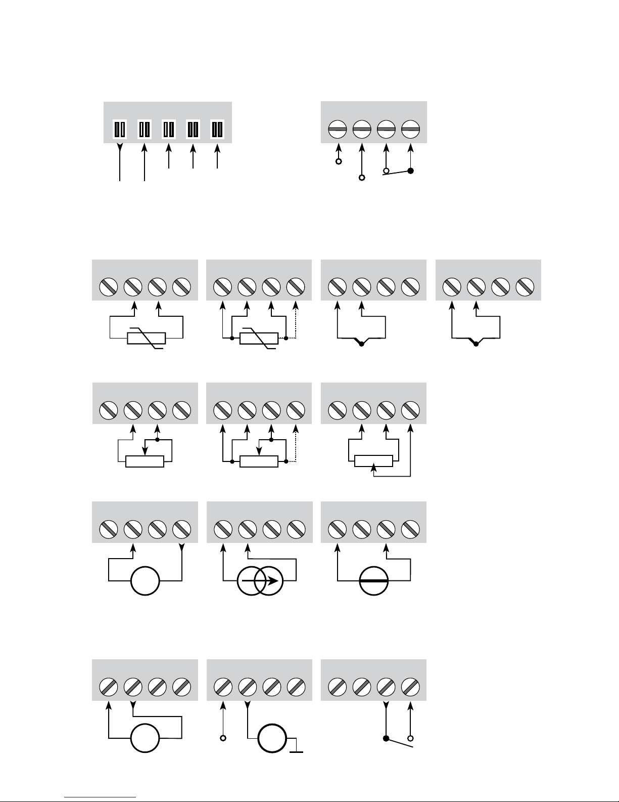
31 32 33 34
11 12 13 14
51 52 53 54
+
-
51 52 53 54
+
-
41 42 43 44 41 42 43 44
41 42 43 44 41 42 43 44
+
-
41 42 43 44
41 42 43 44
+
-
41 42
51 52 53 54
+
-
Tx
11 12 13 14
+
-
mA
mA
+
11 12 13 14
N.O.
+24 V
N.C.
91 92 93 94 95
NCNC
+24 V
1 3
2
9116 - Product Version 9116-001 17
TILSLUTNINGER
Indgange:
Udgange:
Forsyning og
statusrelæ
Strøm
(Aktiv udgang)
Relæ
RTD, 3- / 4-lederRTD, 2-leder
Modstand, 2-leder
Modstand,
3- / 4-leder
Potentiometer
Strøm Spænding2-trådstransmitter
Gnd.
2-trådstransmitter
(Passiv udgang)
* Bestilles særskilt:
CJC-klemme
5910Ex.
Gnd.
Power Rail
forbindelser
NC = ingen forbindelse
Fejl-signal
TC, intern
CJC-føler
*TC,
CJC-klemme
Page 20
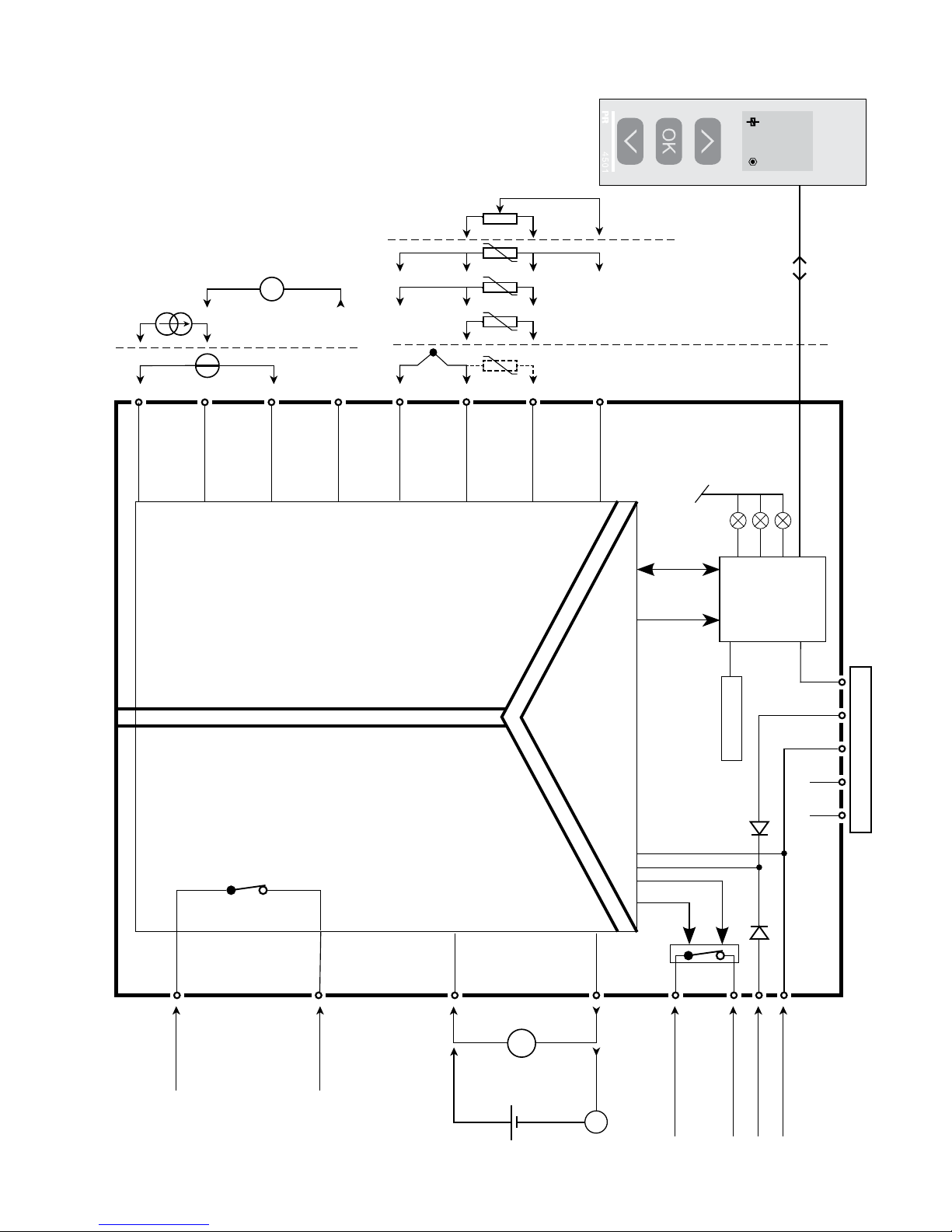
9116
51
31
14
32
34
33
12
11
13
54
53
52
44
43
42
41
NC*NC*
+24V
CPU
FLASH
I
o20 mA
I
800.0
1
+
-
+
-
Tx
4
3
2
*
+
-
I+
mA
mA
+
-
18 9116 - Product Version 9116-001
BLOKDIAGRAM
Modulstatus,
Grøn
Relæstatus, Gul
Kanalstatus, Rød
Statusrelæ N.C.
Statusrelæ N.C.
Gnd.
Forsyning +24 VDC
Relæ N.O.
Relæ N.O.
Gnd.
Power rail forbindelser
Indgang
RTD, forbind.
ledere
Potentiometer
TC
Spæn-
ding
Strøm
mA-
udgang
Forsyning
Relæ-
udgang
* NC = ingen forbindelse
Page 21
9116 - Product Version 9116-001 19
Visning af signal- og kabelfejl uden displayfront
Liste over LED- og fejlsignalvisninger
Tilstand Grøn LED
Relæ:
Gul LED
Fejl:
Rød LED
Statusrelæ,
N.C.
Power rail
signalstatus
Ingen forsyning OFF OFF OFF Sluppet Lukket
Modul defekt OFF ON Sluppet Lukket
Modul OK Blinker Trukket Åben
Signal OK Blinker OFF Trukket Åben
Udgangsrelæ trukket Blinker ON OFF Trukket Åben
Udgangsrelæ trukket pga.
kabelbrud/-kortslutning
Blinker ON Blinker Sluppet
Lukket
(hvis aktiveret)
Udgangsrelæ sluppet pga.
kabelbrud/-kortslutning
Blinker OFF Blinker Sluppet
Lukket
(hvis aktiveret)
Udgangsrelæ sluppet Blinker OFF OFF Trukket Åben
Page 22

20 9116 - Product Version 9116-001
PROGRAMMERING /
BETJENING AF TRYKKNAPPER
Dokumentation til rutediagram
Generelt
Når du skal konfigurere 9116, bliver du guidet igennem samtlige parametre og
kan vælge netop de indstillinger, der passer til applikationen. Til hver menu
findes en rullende hjælpetekst, som vises i displaylinie 3.
Konfigurationen udføres ved hjælp af de 3 taster:
1 forøger talværdien eller vælger næste parameter
2formindsker talværdien eller vælger forrige parameter
3accepterer valget og går til næste menu
Når konfigurationen er gennemført, returneres til normaltilstand 1.0.
Tryk og hold
3 tasten nede for at gå til forrige menu eller normaltilstand (1.0)
uden at gemme de ændrede tal eller parametre.
Hvis ingen taster har været aktiveret i 1 minut, returnerer displayet til normaltil-
stand (1.0) uden at gemme de ændrede tal eller parametre.
Uddybende forklaringer
Passwordbeskyttelse: Programmeringsadgang kan forhindres ved indkodning
af et password. Passwordet gemmes i konverteren, så sikkerheden mod uønskede ændringer er så høj som muligt. Default password 2008 giver adgang
til alle programmeringsmenuer. Passwordbeskyttelse er obligatorisk i SILapplikationer.
Valg af units
Efter valg af indgangstype kan man vælge, hvilke procesenheder der skal vises
i displayet (se skema). Ved valg af temperaturindgang vises pocesværdien
altid i Celsius eller Fahrenheit. Vælges i menupunktet efter valg af temperaturindgang.
CJC
Det er via menuen CJC muligt at vælge mellem ekstern CJC-klemme, og intern
CJC-kompensering. CJC-klemmen (PR5910Ex) bestilles særskilt.
Page 23

9116 - Product Version 9116-001 21
Signal- og følerfejlsinformation via displayfront 4501
Følerfejl (se grænser i skema) vises i display med SE.BR (sensor break) eller
SE.SH (sensor short). Signaler uden for det valgte område (ikke følerfejl, se
skema for grænser) vises i display som IN.LO (lavt indgangssignal) eller IN.HI
(højt indgangssignal). Fejlindikeringen vises i tekst i 1. linie, samtidig med at
baggrundsbelysningen blinker. 4. linie i displayet er en statuslinie, der viser,
om modulet er SIL-låst (statisk prik = SIL-låst og blinkende prik = ikke SILlåst) samt status for relæ og kommunikation (prik med løbende cirkel) som
indikerer, om 4501 fungerer korrekt.
Signal- og følerfejlsindikering uden displayfront:
Status på enheden kan aflæses på de 3 LED’s i fronten af modulet.
Grøn blinkende LED indikerer normal drift.
Ingen lys i grøn LED indikerer manglende forsyningsspænding eller modulfejl.
Konstant rød LED indikerer fatal fejl.
Rød blinkende LED indikerer følerfejl.
Relæfunktioner
Der kan vælges mellem 5 forskellige relæfunktions-opsætninger.
Setpunkt: Enheden fungerer som enkel grænsekontakt.
Window: Relæet har et vindue, der defineres med et lavt og et højt
setpunkt. På begge sider af vinduet har relæet samme status.
Fejlfunktion: Relæet aktiveres ved følerfejl.
Power: Relæet er trukket, så længe der er forsyning på enheden.
Off: Relæet er deaktiveret.
Stigende/faldende: Relæet kan sættes til at blive aktivt for et stigende eller
faldende indgangssignal.
Forsinkelse: Der kan sættes både en ON- og en OFF-forsinkelse i området
0...3600 sekunder.
Hysterese: Der kan sættes en hysterese på 0,1...25% af span eller mellem 1 og
25% af displayområdet.
Vindue: Funktionen vindue opnås ved at vælge setpunkt ”vindue” i menuen og
sætte øvre og nedre setpunkter.
Se den grafiske afbildning af relæfunktionen vindue på side 30.
Page 24

22 9116 - Product Version 9116-001
Setpunkt: Funktionen setpunkt opnås ved at vælge setpunkt i menuen og
indtaste den ønskede grænse. Enheden fungerer derved som en enkelt grænsekontakt.
Se den grafiske afbildning af relæfunktionen setpunkt på side 31.
At relæet er aktiveret betyder, at kontakten er lukket, hvis ”normalt åben” kon-
taktfunktionen er valgt, og kontakten er åben, hvis ”normalt lukket” kontaktfunktionen er valgt.
Forsinkelsestid for ind- og udkobling kan stilles uafhængig af hinanden hen-
holdsvis i menuerne ON.DEL og OFF DEL.
Avancerede funktioner
Enheden giver adgang til en række avancerede funktioner, der nås ved at svare
”YES” til punktet ”ADV.SET”.
Display setup: Her kan man justere kontrast og baggrundsbelysning.
Opsætning af TAG-nummer med 5 alfanumeriske karakterer. Indgangsværdi
vises altid i linie 2 på displayet. Valg af funktionsvisning i linie 3 på displayet der vælges mellem visning af analog udgang og TAG-nummer eller vekslende
displayvisning.
2-punkts proceskalibrering: Enheden kan proceskalibreres til et aktuelt ind-
gangssignal i 2 punkter. Der påtrykkes et lavt indgangssignal (ikke nødvendigvis 0%), og den aktuelle værdi angives på 4501. Herefter påtrykkes et
højt signal (ikke nødvendigvis 100%), og den aktuelle værdi angives på 4501.
Såfremt man siger ja til at bruge kalibreringen, vil enheden herefter arbejde i
henhold til denne nye justering. Siger man senere nej i dette punkt eller vælger en anden indgangssignaltype, går enheden tilbage til fabrikskalibreringen.
Processimulerings-funktion: Vælger man ja til punktet ”EN.SIM”, er det muligt
med piltasterne at simulere et indgangssignal og dermed styre udgangssignalet op og ned, eller relætilstanden OFF eller ON. SIM-menuen skal forlades
ved at trykke 3 (ingen time-out). Hvis 4501 fjernes, afbrydes processimuleringen.
Password: Her kan vælges et password mellem 0000 og 9999 til beskyttelse
mod uautoriserede ændringer. Enheden leveres default uden password.
Page 25

9116 - Product Version 9116-001 23
Memory
I memory menuen er det muligt at gemme opsætningen fra enheden i 4501, for
derefter at flytte 4501 over på en anden enhed og uploade opsætningen til
denne.
Sprog: Der kan i menuen ”LANG” vælges mellem 7 forskellige sprogvarianter
af hjælpetekster, der fremkommer i menuen. Der kan vælges mellem UK, DE,
FR, IT, ES, SE og DK.
Power rail: I menuen ”RAIL” vælges om følerfejl skal overføres til en central
overvågning i PR 9410 power control unit.
Safety Integrity Level: Se Safety Manual for yderligere
information.
Page 26
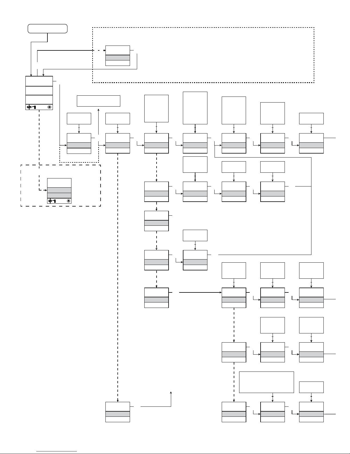
1
0000
PASSW.
Txt 1
Io12.00mA
3
3
0000
9999
1 2
NO
ADV.SET
Txt 2
NO
YES
1 2
3
VOLT
IN TYPE
Txt 3
VOLT
LIN.R
POTM
CURR
TEMP
1 2
3
50.0
SETP.
Txt 57
3
1 2
2-10
V.RANGE
Txt 4
2-10
0-10
1-5
0-5
0.2-1
0-1
1 2
3
TEMP
IN TYPE
Txt 3
3
Pt
SENSOR
Txt 10
Pt
NI
TC
1 2
3
YES
ADV.SET
3
Ni
SENSOR
Txt 10
3
TC
SENSOR
3
100
Pt TYPE
Txt 16
1000
-
10
1 2
3
3W
CONNEC.
Txt 6
4W
3W
2W
1 2
100
Ni TYPE
Txt 17
1000
-
50
1 2
TC.K
TC.TYPE
TC.B TC.E TC.J TC.K
TC.L TC.N TC.R TC.S
TC.T TC.U TC.W3
TC.W5 TC.Lr
1 2
0.0
DISP.LO
Txt 13
999.9
-199.9
1 2
111.1
DEC.P
Txt 12
1111
111.1
11.11
1.111
1 2
3
UNIT
%
Txt 11
@C
mA
rpm
(70 units)
1 2
3
CURR
IN TYPE
Txt 3
3
4-20
I.RANGE
Txt 5
0-20
4-20
1 2
3
LIN.R
IN TYPE
Txt 3
3
3W
CONNEC.
Txt 6
4W
3W
2W
1 2
3
POTM
IN TYPE
Txt 3
3
0
R 0%
Txt 7
0000
9999
1 2
3
0
R 100%
Txt 8
0000
9999
1 2
3
1.0
1.2
1.1
3
3W
CONNEC.
Txt 6
4W
3W
2W
1 2
3
3W
CONNEC.
Txt 6
4W
3W
2W
1 2
3
CJC
INT
CONN
1 231 2
SE.BR
o3.50mA
INT
I
I
30.00
Txt 2 Txt 10 Txt 18 Txt 31
Power up
24 9116 - Product Version 9116-001
Fortsættes på siden
Rutediagram ADV.SET
Hvis SIL-låst
direkte til [EN.SIL]
Rød tekst viser safety
parametre i en SILkonfiguration. Se Safety
Manual for yderligere
information.
Hurtig setpunktsindstilling
og test af relæ
1 Forøgelse af setpunkt
2 Formindskelse af setpunkt
3 Gem og forlad menuen
1 og 2 samtidig = relæ skifter tilstand
Eksempel på fejlvisning
Page 27
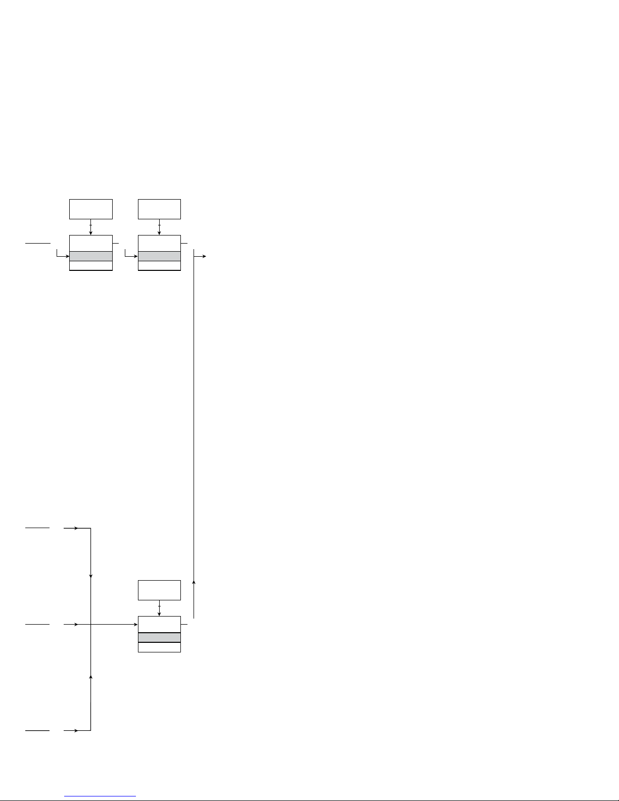
@C
@F
K
%
m
cm
mm
um
ft
in
mils
yd
m3
l
s
min
m/s
mm/s
m/min
m/h
in/s
ips
ft/s
in/min
ft/min
in/h
ft/h
m/s2
rpm
Hz
t
kg
g
N
Pa
MPa
kPa
hPa
bar
mbar
kj
Wh
MWh
kWh
W
GW
MW
kW
hp
A
kA
mA
uA
V
kV
mV
ohm
S
uS
m3/min
m3/h
l/s
l/min
l/h
gal/min
gal/h
t/h
mol
pH
[blank]
Txt 9
3
100.0
DISP.HI
Txt 14
999.9
-199.9
1 2
3
DISP
REL.UNI
Txt 15
DISP
PERC
1 2
@C
UNIT
@C
@F
1 2
3
3
3
3
3
9116 - Product Version 9116-001 25
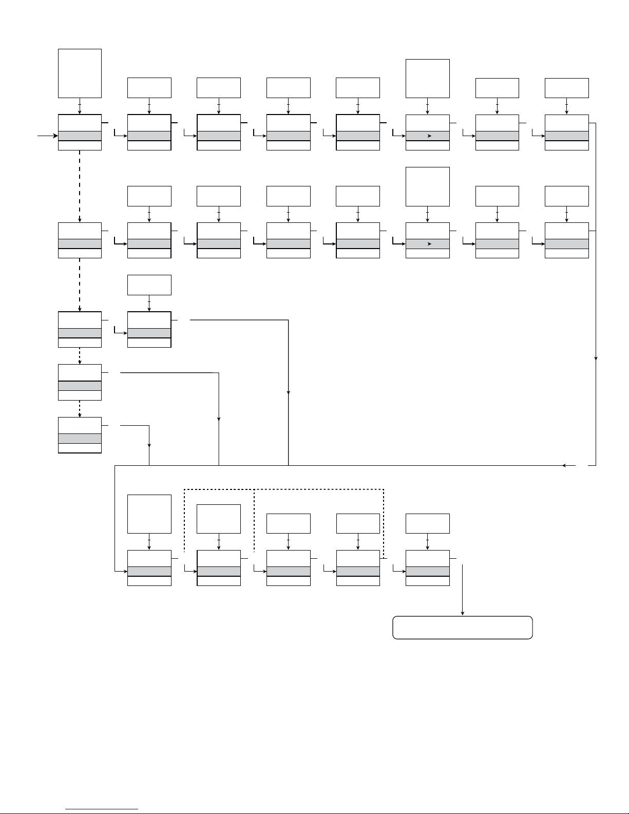
RUTEDIAGRAM
Hvis ingen taster har været aktiveret i 1 minut, returnerer displayet til normaltilstanden 1.0 uden at gemme eventuelle konfigurationsændringer.
1 Forøgelse af værdi / vælg næste parameter
2 Formindskelse af værdi / vælg forrige parameter
3 Accepter valget og gå til næste menu
Holde 3 går til forrige menu / returnerer til 1.0 uden at gemme
Fortsættes næste side
Valgbare
UNIT:
1.0 = Normaltilstand. Linie 1
viser indgangsstatus.
Linie 2 viser indgangsværdi
og TAG nr. Linie 3 viser
udgangsværdi og enheder.
Linie 4 viser relæ- og kom munikationsstatus samt om
modulet er SIL-låst. Statisk
prik = SIL-låst og blinkende
prik = ikke SIL-låst.
1.1 = Kun hvis beskyttet med
password.
1.2 = Kun hvis FastSet er aktive ret, og relæfunktionen
er setpunkt.
1.3 = Kun hvis indgangstyper
understøtter følerfejls check.
Gælder ikke for følgende
indgangssignaler:
0...20 mA og spænding.
1.4 = Kun hvis indgangssignalet
er temperatur.
1.5 = Kun hvis opsætning ikke er
beskyttet med password.
Page 28
0
ON.DEL
Txt 25
3600
0000
1 2
NONE
ERR.ACT
Txt 24
HOLD
CLOS
OPEN
NONE
1 2
3
0
OFF.DEL
Txt 26
3600
0000
1 2
3
0
ON.DEL
Txt 25
3600
0000
1 2
NONE
ERR.ACT
Txt 24
HOLD
CLOS
OPEN
NONE
1 2
3
0
OFF.DEL
Txt 26
3600
0000
1 2
3
3
1.3
1.3
4-20
O.RANGE
Txt 37
20-4
20-0
4-20
0-20
1 2
3
23mA
OUT.ERR
Txt 38
23mA
0/3.5mA
NONE
1 2
3
0.0
OUT.LO
Txt 41
849
-200
1 2
3
150.0
OUT.HI
Txt 42
850.0
-199.0
1 2
1.3
1.4 1.4
3
0.0
RESP.
Txt 39
0.0
60
1 2
N.O.
CONTAC
Txt 20
3
N.O.
N.C.
1 2
50.0
SETP.
Txt 21
850
-200
1 2
3
INCR
ACT.DIR
Txt 22
INCR
DECR
1 2
3
1.0
HYST.
Txt 23
262.5
0.1
1 2
SETP
REL.FUN
Txt 19
SETP
WIND
ERR
POW
OFF
1 2
3
O.I.W
CONTAC
Txt 27
3
O.I.W
C.I.W
1 2
50.0
SETP.LO
Txt 28
849.9
-200
1 2
3
60.0
SETP.HI
Txt 28
850.0
-199.9
1 2
3
1.0
HYST.
Txt 30
262.5
0.1
1 2
WIND
REL.FUN
Txt 19
3
OPEN
ERR.ACT
Txt 34
3
CLOS
OPEN
1 2
ERR
REL.FUN
Txt 19
3
POW
REL.FUN
Txt 19
OFF
REL.FUN
Txt 19
3
3
1.3
3
3
3
26 9116 - Product Version 9116-001
Til normaltilstand 1.0
Page 29
SAVE
MEMORY
Txt 44
3
SAVE
LOAD
1 2
MEM
SETUP
Txt 43
MEM, DISP,
PASS, LANG,
CAL, RAIL,
SIM, SIL
1 2
3
DISP
SETUP
Txt 43
3
3
CONTRA
Txt 45
3
9
0
1 2
9
LIGHT
Txt 46
3
9
0
1 2
TAG.1
TAGNO
Txt 47
3
9
A
1 2
A.OUT
DISP
Txt 48
3
TAG
ALT
A.OUT
1 2
CAL
SETUP
Txt 43
3
YES
CAL.LO
Txt 49
3
YES
NO
1 2
2.0
@C
Txt 61
3
850.0
-200.0
1 2
NO
YES
CAL.HI
Txt 50
3
YES
NO
1 2
147.8
@C
Txt 62
3
850.0
-200.0
1 2
NO
3
USE.CAL
Txt 60
YES
NO
1 2
SIM
SETUP
Txt 43
3
YES
EN.SIM
Txt 51
3
YES
NO
1 2
23.0
%
Txt 52
3
850.0
-200.0
1 2
NO
REL.SIM
Txt 53
3
2.0
RAIL
SETUP
Txt 43
3
YES
RAIL.ER
Txt 63
3
YES
NO
1 2
SIL
SETUP
Txt 43
3
YES
EN.SIL
Txt 64
YES
NO
1 2
NO
3
2008
NEW.PAS
Txt 55
0000
9999
1 2
3
LOCK
CONFIG
Txt 66
SIL.OK
. . . . . . . . . . . . . .
3 3 3 3 3
OPEN
LOCK
1 2
LANG
SETUP
Txt 43
3
UK
LANGUA
Txt 59
3
DE, DK, ES, FR,
IT, SE, UK
1 2
PASS
SETUP
Txt 43
3 3
YES
EN.PASS
Txt 54
3
YES
NO
1 2
NO
0000
NEW.PAS
Txt 55
3
9999
0000
1 2
YES
EN.FAST
Txt 56
YES
NO
1 2
3
YES
1.4
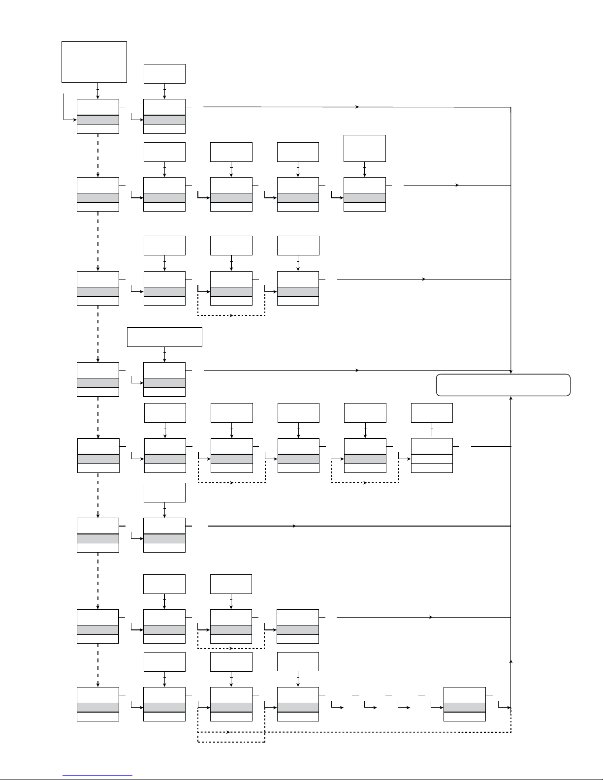
9116 - Product Version 9116-001 27
RUTEDIAGRAM
AVANCEREDE INDSTILLINGER (ADV.SET)
Til normaltilstand 1.0
Verificer SIL-konfiguration
2.0 I undermenuen simulering (SIM) skal 3
trykkes for at returnere til normaltilstand 1.0
Page 30

28 9116 - Product Version 9116-001
[01]
[02]
[03]
[04]
[05]
[06]
[07]
[08]
[09]
[10]
[11]
[12]
[13]
[14]
[15]
[16]
[17]
[18]
[19]
[20]
[21]
[22]
[23]
[24]
[25]
[26]
[27]
[28]
[29]
[30]
[31]
[34]
[37]
[38]
[39]
[41]
[42]
[43]
[44]
[45]
[46]
[47]
[48]
[49]
[50]
[51]
[52]
[53]
[54]
[55]
[56]
[57]
[58]
[59]
[60]
[61]
[62]
[63]
Angiv korrekt password
Gå til avanceret opsætningsmenu?
Vælg temperaturindgang
Vælg potentiometerindgang
Vælg lineær modstandsindgang
Vælg strømindgang
Vælg spændingsindgang
Vælg 0.0-1 V indgangsområde
Vælg 0.2-1 V indgangsområde
Vælg 0-5 V indgangsområde
Vælg 1-5 V indgangsområde
Vælg 0-10 V indgangsområde
Vælg 2-10 V indgangsområde
Vælg 0-20 mA indgangsområde
Vælg 4-20 mA indgangsområde
Vælg 2-leder følertilslutning
Vælg 3-leder følertilslutning
Vælg 4-leder følertilslutning
Indstil modstandsværdi lav
Indstil modstandsværdi høj
Vælg Celsius som temperaturenhed
Vælg Fahrenheit som temperaturenhed
Vælg TC-følertype
Vælg Ni-følertype
Vælg Pt-følertype
Vælg displayenheder
Vælg kommaplacering
Indstil displayområde lav
Indstil displayområde høj
Indstil relæ-setpunkt i % af indgangsområde
Indstil relæ-setpunkt i displayenheder
Vælg Pt10 som følertype
Vælg Pt20 som følertype
Vælg Pt50 som følertype
Vælg Pt100 som følertype
Vælg Pt200 som følertype
Vælg Pt250 som følertype
Vælg Pt300 som følertype
Vælg Pt400 som følertype
Vælg Pt500 som følertype
Vælg Pt1000 som følertype
Vælg Ni50 som følertype
Vælg Ni100 som følertype
Vælg Ni120 som følertype
Vælg Ni1000 som følertype
Vælg TC-B som følertype
Vælg TC-E som følertype
Vælg TC-J som følertype
Vælg TC-K som følertype
Vælg TC-L som følertype
Vælg TC-N som følertype
Vælg TC-R som følertype
Vælg TC-S som følertype
Vælg TC-T som følertype
Vælg TC-U som følertype
Vælg TC-W3 som følertype
Vælg TC-W5 som følertype
Vælg TC-LR som følertype
Vælg OFF-funktion - relæ er permanent OFF
Vælg POWER-funktion - relæ viser power-status OK
Vælg FEJL-funktion - relæ viser kun følerfejl
Vælg VINDUE-funktion - relæet styres af 2 setpunkter
Vælg SETPUNKT-funktion - relæet styres af 1 setpunkt
RULLENDE HJÆLPETEKSTER I DISPLAYLINIE 3
Vælg kontakt normalt lukket
Vælg kontakt normalt åben
Indstil relæ-setpunkt
Vælg aktiver relæ ved faldende signal
Vælg aktiver relæ ved stigende signal
Indstil relæ-hysterese
Vælg Ingen følerfejlsaktion - udefineret status ved fejl
Vælg relækontakt bryder ved fejl
Vælg relækontakt slutter ved fejl
Vælg hold relæstatus ved fejl
Indstil relæ ON-forsinkelse i sekunder
Indstil relæ OFF-forsinkelse i sekunder
Vælg relækontakt er åben inden for vinduet
Vælg relækontakt er lukket inden for vinduet
Indstil setpunkt lav for relævindue
Indstil setpunkt høj for relævindue
Indstil hysterese for relævindue
Vælg Intern temperatur-føler
Vælg CJC-stik (tilbehør)
Vælg relækontakt bryder ved fejl
Vælg relækontakt slutter ved fejl
Vælg 0-20 mA udgangsområde
Vælg 4-20 mA udgangsområde
Vælg 20-0 mA udgangsområde
Vælg 20-4 mA udgangsområde
Vælg Ingen fejlaktion - udgang udefineret ved fejl
Vælg downscale ved fejl
Vælg NAMUR NE43 downscale ved fejl
Vælg NAMUR NE43 upscale ved fejl
Vælg responstid for analog udgang i sekunder
Indstil temperatur for analog udgang lav
Indstil temperatur for analog udgang høj
Gå til valg af SIL låsning
Gå til simuleringstilstand
Gå til valg af fejl til RAIL
Udfør proceskalibrering
Gå til valg af sprog
Gå til password-indstilling
Gå til displayopsætning
Udfør memory-operationer
Overfør gemt opsætning til 9116
Gem 9116-opsætning i 4501
Juster LCD-kontrast
Juster LCD-baggrundsbelysning
Angiv TAG-nr. - udfyld alle pladser
Vis analog udgangsværdi i display
Vis TAG-nr. i display
Skiftende værdier vises i display
Kalibr
er indgang lav til procesværdi?
Kalibrer indgang høj til procesværdi?
Aktiver indgangssimulering
Indstil simuleringsværdi for indgang
Relæsimulering - brug 1 til at skifte relætilstand
Vælg passwordbeskyttelse?
Angiv nyt password
Aktiver Fastset-funktionalitet?
Relæ-setpunkt - tryk 3 for at gemme
Relæ-setpunkt - Read only
Vælg sprog
Brug proceskalibreringsværdier?
Indstil værdi for lavt kalibreringspunkt
Indstil værdi for højt kalibreringspunkt
Vælg om statussignal skal overføres til power rail
Page 31

9116 - Product Version 9116-001 29
[64]
[65]
[66]
[80]
[81]
[82]
[83]
[84]
[85]
[86]
[87]
[88]
[89]
[90]
[91]
[92]
[93]
Vælg at SIL-låse konfigurationen
0-20 mA er ikke gyldigt udgangsområde for drift i
SIL-låst tilstand
...Bruger kanalen proceskompenserede
kalibreringsdata?
Konfigurationens SIL-status (åben / låst)
Følerkabelbrud
Følerkortslutning
Diplay under min.-visning
Display over max.-visning
Indgang uden for max.-område
Indgang uden for min.-område
Fejl på indgang - kontroller indgangsforbindelser og
genstart enheden
Fejl på udgang - kontroller udgangsforbindelser og
genstart enheden
Fejl i FLASH - kontroller konfiguration
Ugyldig konfiguration eller ugyldig version
Hardware fejl
CJC-følerfejl - kontroller enhedens temperatur
CJC-følerfejl - kontroller CJC-stikterminal
Ingen kommunikation
Page 32
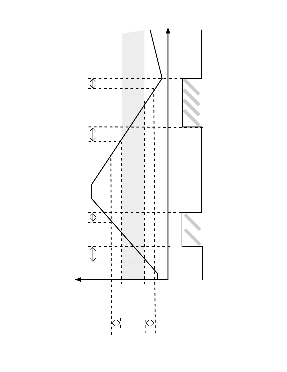
30 9116 - Product Version 9116-001
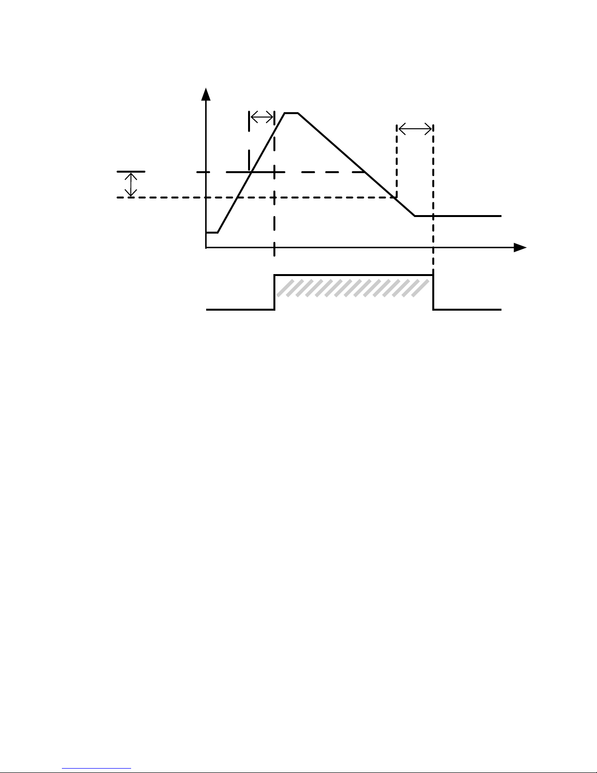
Grafisk afbildning af relæfunktionen vindue
Hysterese
Setpunkt høj
ON-forsinkelse OFF-forsiinkelse
Relæ ON Relæ ON
Lukket
Åben
Relækontakt (N.O.)
Tid
Vindue
ON-forsinkelse OFF-forsiinkelse
Hysterese
Setpunkt lav
Page 33
9116 - Product Version 9116-001 31
Grafisk afbildning af relæfunktionen setpunkt
Relæ ON
OFF-forsinkelse
ON-forsinkelse
Indgangs-
signal
Hysterese
Setpunkt
(stigende)
Tid
Lukket
Åben
Relækontakt
(N.O.)
Page 34

32 9116 - Product Version 9116-001
Page 35

9116 - Product Version 9116-001 33
UNIVERSAL CONVERTER
9116
CONTENTS
Warning .......................................................................................... 34
Safety instructions .......................................................................... 34
How to demount system 9000 ....................................................... 36
EC declaration of conformity ......................................................... 37
Advanced features ......................................................................... 38
Application ..................................................................................... 38
Technical characteristics ................................................................ 38
Applications .................................................................................... 39
PR 4501 Display / programming front ........................................... 40
Order .............................................................................................. 41
Electrical specifications .................................................................. 41
Configuration of sensor error check .............................................. 45
Visualisation in 4501 of:
Input signal outside range ......................................................... 46
Sensor error detection ............................................................... 46
Hardware error ........................................................................... 47
Connections ................................................................................... 49
Block diagram ................................................................................ 50
Signal error and cable fault indications without display front ........ 51
Configuration / operating the function keys .................................. 52
Routing diagram ............................................................................. 57
Routing diagram, Advanced settings (ADV.SET) ............................ 59
Scrolling help texts in display line 3 ............................................... 60
Graphic depiction of window ......................................................... 62
Graphic depiction of setpoint ........................................................ 63
Appendix ........................................................................................ 128
IECEx Installation Drawing......................................................... 129
ATEX Installation Drawings, UK, FR, DE, DK ............................ 133
FM Installation Drawing ............................................................. 149
Safety Manual ............................................................................ 153
Page 36
34 9116 - Product Version 9116-001
SYMBOL IDENTIFICATION
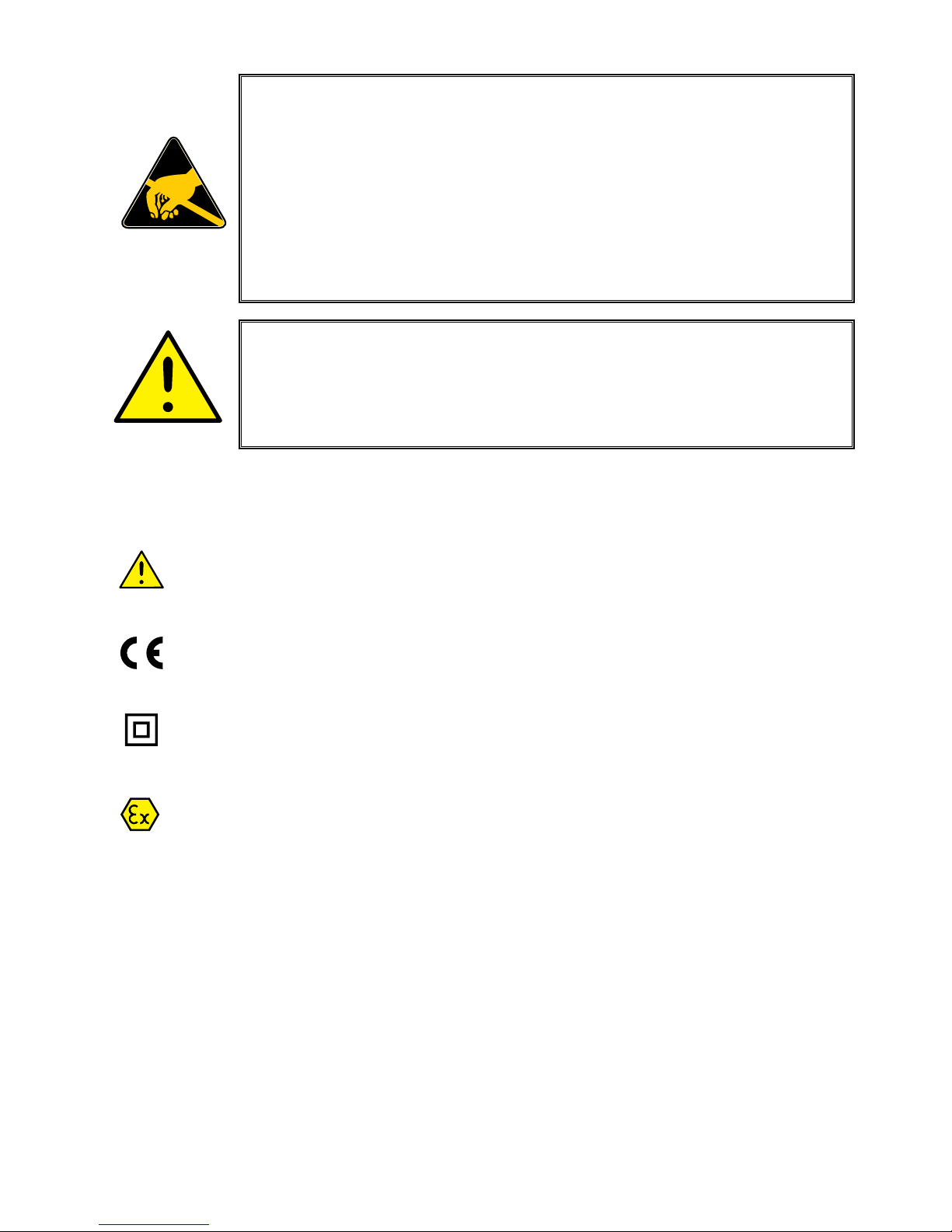
Triangle with an exclamation mark: Read the manual before installation
and commissioning of the device in order to avoid incidents that could
lead to personal injury or mechanical damage.
The CE mark proves the compliance of the device with the essential
requirements of the directives.
The double insulation symbol shows that the device is protected by
double or reinforced insulation.
Ex devices have been approved according to the ATEX directive for
use in connection with installations in explosive areas. See installation
drawings in appendix.
SAFETY INSTRUCTIONS
DEFINITIONS
Hazardous voltages have been defined as the ranges: 75...1500 Volt DC, and
50...1000 Volt AC.
Technicians are qualified persons educated or trained to mount, operate, and
also troubleshoot technically correct and in accordance with safety regulations.
Operators, being familiar with the contents of this manual, adjust and operate
the knobs or potentiometers during normal operation.
WARNING
The following operations should only be carried out on a
disconnected device and under ESD-safe conditions:
General mounting, connection and disconnection of wires.
Troubleshooting the device.
Repair of the device and replacement of circuit breakers
must be done by PR electronics A/S only.
WARNING
Do not open the front plate of the device as this will cause
damage to the connector for the display / programming front
PR 4501. This device contains no DIP-switches or jumpers.
Page 37

9116 - Product Version 9116-001 35
RECEIPT AND UNPACKING
Unpack the device without damaging it and check whether the device type
corresponds to the one ordered. The packing should always follow the device
until this has been permanently mounted.
ENVIRONMENT
Avoid direct sunlight, dust, high temperatures, mechanical vibrations and shock,
as well as rain and heavy moisture. If necessary, heating in excess of the stated
limits for ambient temperatures should be avoided by way of ventilation.
The device must be installed in pollution degree 2 or better.
The device is designed to be safe at least under an altitude up to 2 000 m.
MOUNTING
Only technicians who are familiar with the technical terms, warnings, and
in struc tions in the manual and who are able to follow these should connect the
device.
Should there be any doubt as to the correct handling of the device, please
contact your local distributor or, alternatively,
PR electronics A/S, Lerbakken 10, 8410 Rønde, Danmark tlf: +45 86 37 26 77.
The use of stranded wires is not permitted for mains wiring except when wires
are fitted with cable ends.
Descriptions of input / output and supply connections are shown in the block
diagram and on the side label.
The device is provided with field wiring terminals and shall be supplied from a
Power Supply having double / reinforced insulation. A power switch shall be
easily accessible and close to the device. The power switch shall be marked as
the disconnecting unit for the device.
For installation on Power Rail 9400 the power is supplied by Power Control Unit
9410.
Year of manufacture can be taken from the first two digits in the serial number.
CALIBRATION AND ADJUSTMENT
During calibration and adjustment, the measuring and connection of external
voltages must be carried out according to the specifications of this manual. The
technician must use tools and instruments that are safe to use.
Page 38
36 9116 - Product Version 9116-001
NORMAL OPERATION
Operators are only allowed to adjust and operate devices that are safely fixed
in panels, etc., thus avoiding the danger of personal injury and damage. This
means there is no electrical shock hazard, and the device is easily accessible.
CLEANING
When disconnected, the device may be cleaned with a cloth moistened with
distilled water.
LIABILITY
To the extent the instructions in this manual are not strictly observed, the
customer cannot advance a demand against PR electronics A/S that would
otherwise exist according to the concluded sales agreement.
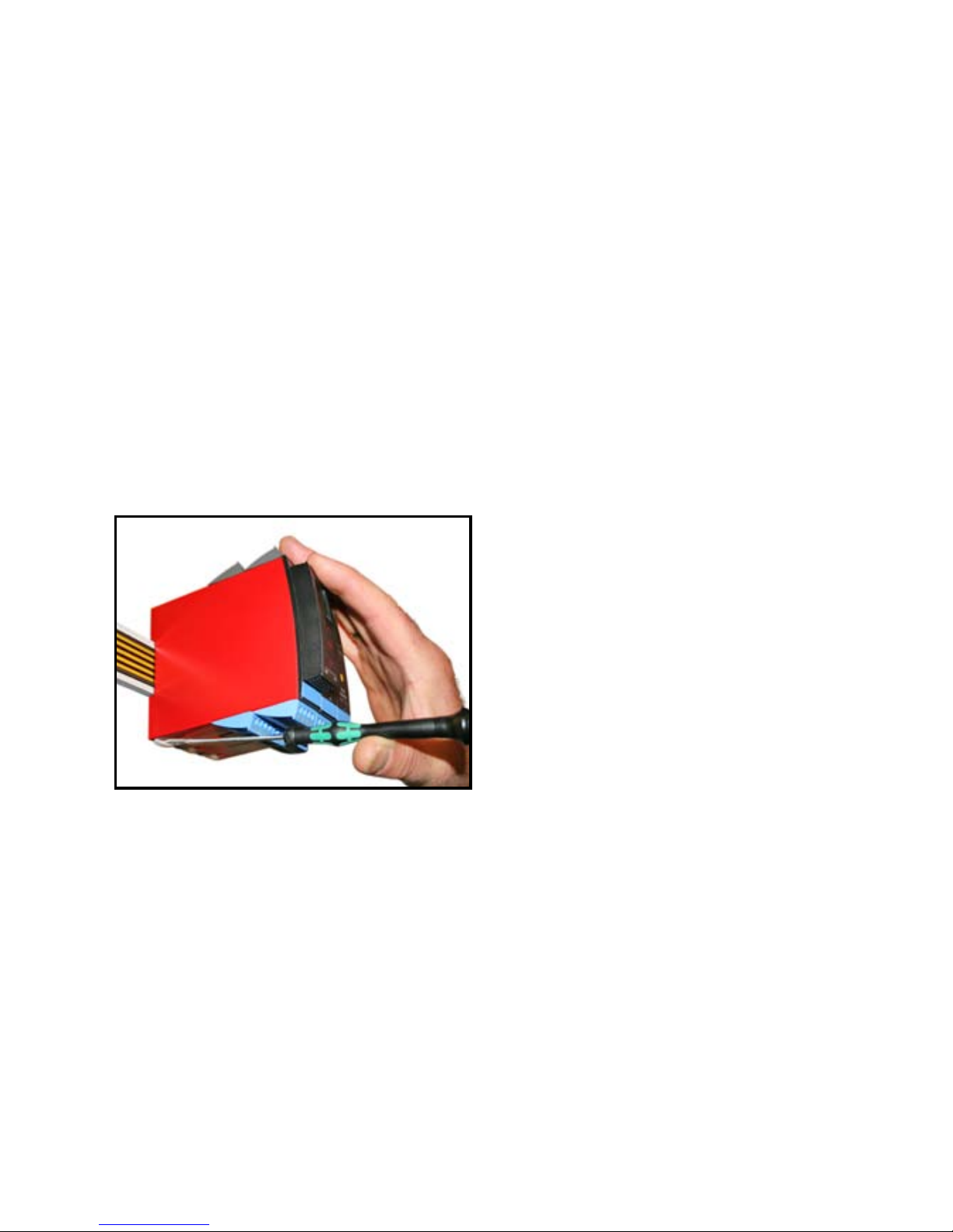
HOW TO DEMOUNT SYSTEM 9000
Picture 1:
By lifting the bottom lock, the device
is detached from the power rail.
Page 39

9116 - Product Version 9116-001 37
EC DECLARATION OF CONFORMITY
As manufacturer
PR electronics A/S
Lerbakken 10
DK-8410 Rønde
hereby declares that the following product:
Type: 9116
Name: Universal converter
is in conformity with the following directives and standards:
The EMC Directive 2004/108/EC and later amendments
EN 61326-1 : 2006
For specification of the acceptable EMC performance level, refer to the
electrical specifications for the device.
The Low Voltage Directive 2006/95/EC and later amendments
EN 61010-1 : 2001
The ATEX Directive 94/9/EC and later amendments
EN 61241-0 : 2006, EN 61241-11 : 2006, EN 60079-0 : 2006,
EN 60079-11 : 2007, EN 60079-15 : 2005, EN 60079-26 : 2007
ATEX certificate: KEMA 07ATEX0149 X
Notified body
KEMA Quality B.V. (0344)
Utrechtseweg 310, 6812 AR Arnhem
P.O. Box 5185, 6802 ED Arnhem
The Netherlands
Rønde, 15 January 2010 Kim Rasmussen
Manufacturer’s signature
Page 40

38 9116 - Product Version 9116-001
UNIVERSAL CONVERTER
9116
• Input for RTD, TC, Ohm, potentiometer, mA and V
• Supply for 2-wire transmitters
• Active / passive mA output and relay output
• Can be supplied separately or installed on power rail, PR 9400
• SIL 2-certified via Full Assessment
Advanced features
• Configuration and monitoring by way of detachable display front (PR 4501);
process calibration, signal and relay simulation.
• Advanced relay configuration, e.g. setpoint, window, delay, sensor error
indication and power monitoring.
• Copying of the configuration from one device to others of the same type via
PR4501.
• Reduced Uo Ex data < 8.3 V for active input signals.
• TC inputs with internal or external CJC for higher accuracy.
• The device automatically detects whether it must supply an active or a
passive current signal.
Application
• Can be mounted in the safe area and in zone 2 / div. 2 and receive signals
from zone 0, 1, 2, 20, 21 and 22 / Class I/II/III, Div. 1, Gr. A-G.
• Conversion and scaling of temperature, voltage, potentiometer and linear
resistance signals.
• Power supply and signal isolator for 2-wire transmitters.
• Monitoring of error events and cable breakage via the individual status relay
and/or a collective electronic signal via the power rail.
• The 9116 has been designed, developed and certified for use in SIL 2
applications according to the requirements of IEC 61508.
Technical characteristics
• 1 green and 1 red front LED indicate operation status and malfunction. 1
yellow LED indicates relay status.
• 2.6 kVAC galvanic isolation between input, output and supply.
Page 41
*
+
-
mA
mA
+
44
43
42
41
12
11
14
13
+
+
+
-
Tx
54
53
52
51
31
32
33
34
9116 - Product Version 9116-001 39
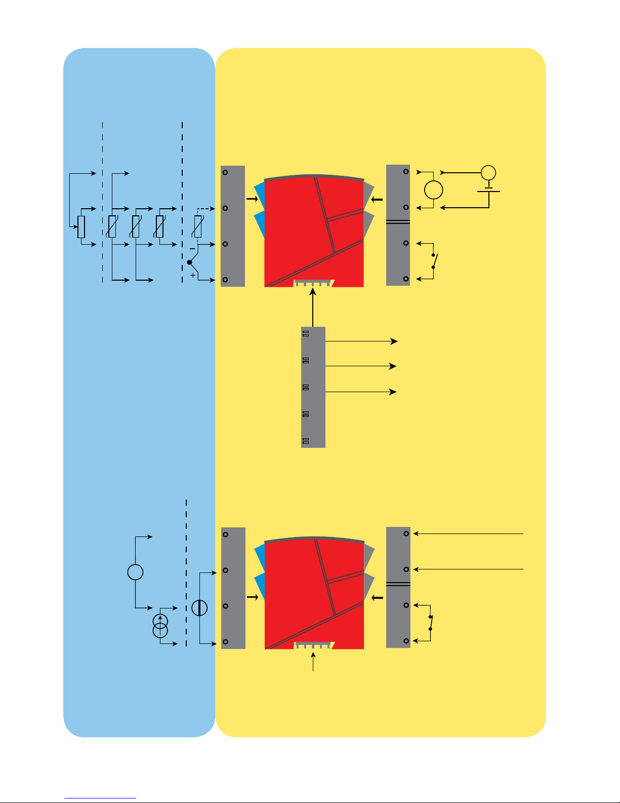
APPLICATIONS
Input signals:
Poten-
tiometer
TC
RTD and lin. R
Connection, wires
Analogue, 0/4...20 mA and relay
Relay
Relay
N.O.
Rail, +24 VDC
Rail, Gnd.
Power rail
Status relay signal
Output signals:
* Order separately:
CJC connector 5910Ex
Current
Volt-
age
Device status
Device status
Gnd.
Supply +19.2...31.2 VDC
N.C.
Power connection:
Supply via
power rail
Zone 0, 1, 2,
20, 21, 22 /
Cl. I/II/III, div. 1
gr. A-G
Zone 2 / Cl. 1, div. 2, gr. A-D or safe area
No connection
No connection
Page 42

40 9116 - Product Version 9116-001
PR 4501 DISPLAY / PROGRAMMING FRONT
Functionality
The simple and easily understandable menu structure
and the explanatory help texts guide you effortless ly and
automatically through the configuration steps, thus making
the product very easy to use. Functions and configuration
options are described in the section ”Configuration /
operating the function keys”.
Application
• Communications interface for modification of operational parameters in 9116.
• Can be moved from one 9116 device to another and download the
configuration of the first unit to subsequent units.
• Fixed display for visualisation of process data and status.
Technical characteristics
• LCD display with 4 lines; Line 1 (H=5.57 mm) shows input status, line 2
(H=3.33) mm toggels between input value and tag. no. Line 3 (H=3.33
mm) shows output value and UNIT. Line 4 shows status for relay and
communication and whether the device is SIL-locked. Static dot = SIL-locked
and flashing dot = not SIL-locked.
• Programming access can be blocked by assigning a password. The
password is saved in the device in order to ensure a high degree of
protection against unauthorised modifications to the configuration.
Mounting / installation
• Click 4501 onto the front of 9116.
Page 43

9116 - Product Version 9116-001 41
Order
9116B1 = Universal converter - Uo 28 VDC (max. loop voltage)
9116B2 = Universal converter - Uo 22 VDC (max. loop voltage)
4501 = Display / programming front
5910Ex = CJC connector
9400 = Power rail
Electrical specifications
Specifications range .................................... -20°C to +60°C
Storage temperature ................................... -20°C to +85°C
Common specifications:
Supply voltage, DC ..................................... 19.2...31.2 VDC
Max. consumption....................................... ≤ 3.5 W
Fuse ............................................................. 1.25 A SB / 250 VAC
Isolation voltage, test / operation ............... 2.6 kVAC / 250 VAC
Communications interface .......................... Programming front 4501
Signal / noise ratio ...................................... Min. 60 dB (0...100 kHz)
Response time (0...90%, 100...10%):
Temperature input, programmable .......... 1...60 s
mA / V input, programmable ................... 0.4...60 s
Calibration temperature............................... 20...28°C
Accuracy, the greater of the general and basic values:
General values
Input
type
Absolute
accuracy
Temperature
coefficient
All ≤ ±0.1% of span ≤ ±0.01% of span / °C
Page 44
42 9116 - Product Version 9116-001
Auxiliary supplies for 9116B1:
2-wire supply (terminal 54...52) ................... 28...16.5 VDC / 0...20 mA
Auxiliary supplies for 9116B2:
2-wire supply (terminal 54...52) ................... 22...16.5 VDC / 0...20 mA
Wire size (max....min.) ................................. AWG 26...14 / 0.13...2.08 mm
2
stranded wire
Screw terminal torque ................................. 0.5 Nm
Relative humidity ......................................... < 95% RH (non-cond.)
Dimen., without display front (HxWxD) ....... 109 x 23.5 x 104 mm
Dimensions, with display front (HxWxD) ..... 109 x 23.5 x 116 mm
Protection degree ........................................ IP20
Weight ......................................................... 185 g / 200 g with 4501
EMC immunity influence ..................................... < ±0.5% of span
Extended EMC immunity:
NAMUR NE 21, A criterion, burst ....................... < ±1% of span
Basic values
Input
type
Basic
accuracy
Temperature
coefficient
mA ≤ ±16 µA ≤ ±1.6 µA / °C
Volt ≤ ±20 µV ≤ ±2 µV / °C
Pt100, Pt200,
Pt 1000 ≤ ±0.2°C ≤ ±0.02°C / °C
Pt500, Ni100,
Ni120, Ni 1000 ≤ ±0.3°C ≤ ±0.03°C / °C
Pt50, Pt400, Ni50 ≤ ±0.4°C ≤ ±0.04°C / °C
Pt250, Pt300 ≤ ±0.6°C ≤ ±0.06°C / °C
Pt20 ≤ ±0.8°C ≤ ±0.08°C / °C
Pt10 ≤ ±1.4°C ≤ ±0.14°C / °C
TC type:
E, J, K, L, N, T, U
≤ ±1°C
≤ ±0.1°C / °C
TC type: R, S,
W3, W5, LR
≤ ±2°C
≤ ±0.2°C / °C
TC type: B
160...400°C ≤ ±4.5°C ≤ ±0.45°C / °C
TC type: B
400...1820°C ≤ ±2°C ≤ ±0.2°C / °C
Page 45
9116 - Product Version 9116-001 43
Isolation:
Input to any ................................................. 300 VAC double / reinforced isolation
Output relay to analogue output ................. 150 VAC double/reinforced or
300 VAC basic isolation
Analogue output to supply .......................... 300 VAC double/reinforced isolation
Status relay to supply ................................. 150 VAC double/reinforced or
300 VAC basic isolation
RTD, linear resistance and potentiometer input:
Input for RTD types:
Pt10*, Pt20*, Pt50*, Pt100, Pt200, Pt250, Pt300, Pt400, Pt500, Pt1000
Ni50, Ni100, Ni120, Ni1000
Effect of sensor cable resistance
(3- / 4-wire), RTD ......................................... < 0.002 Ω / Ω
Sensor error detection, RTD ....................... Programmable ON / OFF
Short circuit detection, RTD ........................ Yes
Cable resistance per wire (max.), RTD ........ 50 Ω
Sensor current, RTD .................................... Nom. 0.2 mA
* No short circuit detection for Pt10, Pt20 and Pt50
* No short circuit detection for Lin. R_0%≤app. 18 Ω
TC input:
Input
type
Min.
value
Max.
value
Standard
Pt100
Ni100
Linear resist.
Potentiometer
-200°C
-60°C
0 Ω
10 Ω
+850°C
+250°C
10000 Ω
10000 Ω
IEC60751
DIN 43760
-
-
Type
Min.
value
Max.
value
Standard
B
E
J
K
L
N
R
S
T
U
W3
W5
LR
+0°C
-100°C
-100°C
-180°C
-200°C
-180°C
-50°C
-50°C
-200°C
-200°C
0°C
0°C
-200°C
+1820°C
+1000°C
+1200°C
+1372°C
+900°C
+1300°C
+1760°C
+1760°C
+400°C
+600°C
+2300°C
+2300°C
+800°C
IEC 60584-1
IEC 60584-1
IEC 60584-1
IEC 60584-1
DIN 43710
IEC 60584-1
IEC 60584-1
IEC 60584-1
IEC 60584-1
DIN 43710
ASTM E988-90
ASTM E988-90
GOST 3044-84
Page 46

44 9116 - Product Version 9116-001
Cold junction compensation (CJC):
via external sensor in connector 5910 .... 20...28°C ≤ ±1°C
-20...20°C and 28...70°C ≤ ±2°C
via internal CJC sensor ........................... ±(2.0°C + 0.4°C * ∆t)
∆t = internal temperature - ambient temperature
Sensor error detection ................................ Programmable ON or OFF
(only wire breakage)
Sensor error current:
when detecting ........................................ Nom. 2 µA
else .......................................................... 0 µA
Current input:
Measurement range .................................... 0...20 mA
Programmable measurement ranges .......... 0...20 and 4...20 mA
Input resistance ........................................... Nom. 20 Ω + PTC 50 Ω
Sensor error detection:
Loop break 4...20 mA.............................. Yes
NB: Only when input is selected as 4...20 mA
Voltage input:
Measurement range .................................... 0...10 VDC
Programmable measurement ranges .......... 0...1 / 0.2...1 / 0...5 / 1...5 /
0...10 and 2...10 VDC
Input resistance ........................................... Nom. >10 MΩ
Current output:
Signal range (span) ...................................... 0...20 mA
Programmable signal ranges ...................... 0...20 / 4...20 /
20...0 and 20...4 mA
Load (max.) .................................................. 20 mA / 600 Ω / 12 VDC
Load stability ............................................... ≤ 0.01% of span / 100 Ω
Sensor error reaction ................................... 0 / 3.5 / 23 mA / none
NAMUR NE 43 Upscale / Downscale .......... 23 mA / 3.5 mA
Output limitation:
on 4...20 and 20...4 mA signals .............. 3.8...20.5 mA
on 0...20 and 20...0 mA signals .............. 0...20.5 mA
Current limit ................................................. ≤ 28 mA
2-wire 4...20 mA output:
Signal range ................................................ 4...20 mA
Load stability ............................................... ≤ 0.01% of span / 100 Ω
Load resistance ........................................... ≤ (Vsupply -3.5) / 0.023 A [Ω]
External 2-wire supply range ...................... 3.5...26 VDC
Effect of external 2-wire supply
voltage variation .......................................... < 0.005% of span / V
Page 47

9116 - Product Version 9116-001 45
Relay output in safe area:
Relay functions ............................................ Setpoint, Window, Sensor error,
Power and Off
Hysteresis, in % of span / display range .... 0.1...25 / 1...25
On and Off delay ......................................... 0...3600 s
Sensor error reaction ................................... Break / Make / Hold
Max. voltage ................................................ 250 VAC / 30 VDC
Max. current ................................................ 2 AAC / 2 ADC
Max. AC power ........................................... 500 VA / 60 W
Status relay in safe area:
Max. voltage ................................................ 125 VAC / 110 VDC
Max. current ................................................ 0.5 AAC / 0.3 ADC
Max. AC power ........................................... 62.5 VA / 32 W
Marine approval:
Det Norske Veritas, Ships & Offshore ......... Pending
GOST R approval:
VNIIFTRI, Cert No. ....................................... Pending
SIL certification:
exida, Cert No. ............................................ PREl 070902 P0002 C05
Observed authority requirements: Standard:
EMC 2004/108/EC ...................................... EN 61326-1
LVD 2006/95/EC .......................................... EN 61010-1
ATEX 94/9/EC .............................................. EN 60079-0, -11, -15 , -26
and EN 61241-0, -11
IECEx ........................................................... IEC 60079-0, -11, -15 and -26
IEC 61241-0 and -11
c FM us ....................................................... FM 3600, 3611, 3810
CSA E60079-0, -15
CSA 22.2 -25, -142, -213
ANSI/ISA-12.00.01 / 12.12.02
UL, Standard for Safety .............................. UL 61010-1
SIL ............................................................... IEC 61508
of span = of the currently selected measurement range
Configuration of sensor error check
Sensor error check:
Device: Configuration Sensor error detection:
9116
ERR.ACT=NONE - OUT.ERR=NONE. OFF
Else: ON
Page 48
46 9116 - Product Version 9116-001
Visualisation in 4501 of:
Input signal outside range
Sensor error detection
Outside range readout (IN.LO, IN.HI):
If the valid range of the A/D converter or the polynomal is exceeded.
Input Range Readout Limit
VOLT
0...1 V / 0.2...1 V
IN.LO < -25 mV
IN.HI > 1.2 V
0...10 V / 2...10 V
IN.LO < -25 mV
IN.HI > 12 V
CURR 0...20 mA / 4...20 mA
IN.LO < -1.05 mA
IN.HI > 25.05 mA
LIN.R
0...800
Ω
IN.LO < -10 Ω
IN.HI > 900 Ω
0...10 kΩ
IN.LO <-10 Ω
IN.HI > 11 kΩ
POTM 0 - 100%
IN.LO < -0.5 %
IN.HI > 100.5 %
TEMP TC / RTD
IN.LO < temperature range -2°C
IN.HI > temperature range +2°C
Sensor error detection (SE.BR, SE.SH):
Input Range Readout Condition
CURR Loop break (4...20 mA) SE.BR <= 3.6 mA; > = 21 mA
POTM All, SE.BR on all 3-wire
SE.BR Sensor broken
SE.SH Sensor shorted
LIN.R
All SE.BR
Sensor broken or wire
resistance too high
For Lin. R_0%≥app. 18 Ω SE.SH Sensor shorted
TEMP
All SE.BR
Sensor broken or wire
resistance too high
Pt100 to Pt1000 and Ni50 to Ni1000 SE.SH Sensor shorted
Display readout below . / above max. (-1999, 9999):
Input Range Readout Limit
All All
-1999 Display readout <-1999
9999 Display readout >9999
Page 49
9116 - Product Version 9116-001 47
Hardware error
Readout at hardware error
Error search Readout Cause
CJC sensor error - check device temperature CJ.ER
Defect internal CJC sensor or
CJC temperature out of allowed
range **
CJC connector error - check CJC connector block CJ.CE
Defect (or missing) CJC
connector or temperature out of
allowed range **
Input error - check input connection and reset power IN.ER
Signal levels on input beyond
limits or connected to wrong
terminals*
Output error - check output connections and reset
power
AO.ER
Error in analogue output current
(SIL mode only)*
No communication NO.CO
No communication
with (4501)
Flash memory error - check configuration
FL.ER
CO.ER
FLASH error
(configuration invalid)***
Invalid configuration type or version TY.ER
Configuration read from
EEprom has invalid type or
rev. no.
Hardware error RA.ER RAM error*
Hardware error IF.ER Internal Flash error*
Hardware error SW.ER SW monitor error*
Hardware error AD.ER A/D converter error*
Hardware error AO.SU
Analogue output
supply error*
Hardware error CA.ER Factory calibration error*
Hardware error CM.ER Main CPU error*
Hardware error RE.ER Relay readback error*
Hardware error II.ER Initialization check error*
Hardware error RS.ER Reset error*
Hardware error IC.ER Input communication error*
Hardware error M1.ER Main CPU to Ch.1 error*
Hardware error MC.ER Main CPU config. error*
Hardware error MF.ER Main CPU Flash error*
Hardware error MR.ER Main CPU Ram error*
Hardware error MS.ER Main CPU supply error*
Hardware error MP.ER Main CPU ProgFlow error*
Hardware error MI.ER
Main CPU initialization
check error*
Hardware error DE.ER Device error*
Hardware error FC.ER Invalid code checksum in 4501
Page 50

48 9116 - Product Version 9116-001
! All error indications in the display flash once per second (1 Hz), and the corresponding help
text is shown. If the error is a sensor error, the display backlight flashes as well - this is
acknowledged (stopped) by pushing the OK button.
* Error is acknowledged by resetting the device power
** Error can be disregarded by selecting input type different than TC.
*** Error is acknowledged by stepping through the basic setup.
Page 51
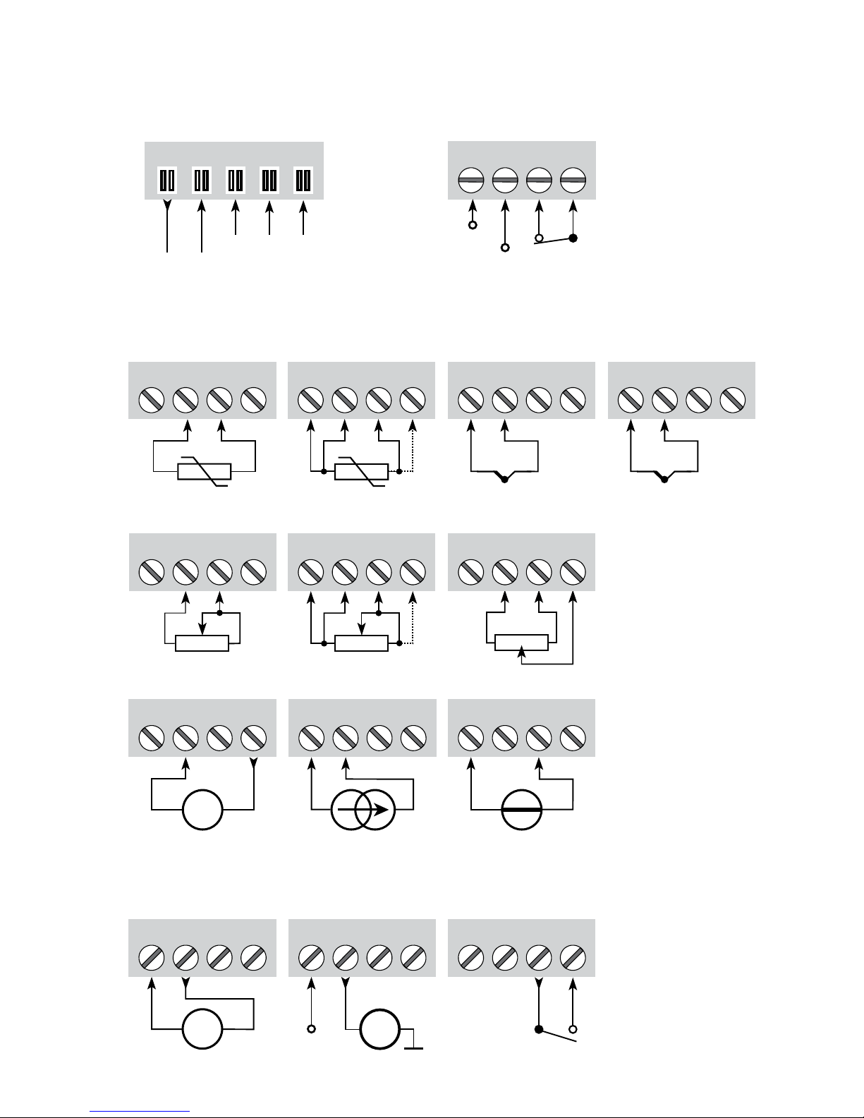
31 32 33 34
11 12 13 14
51 52 53 54
+
-
51 52 53 54
+
-
41 42 43 44 41 42 43 44
41 42 43 44 41 42 43 44
+
-
41 42 43 44
41 42 43 44
+
-
41 42
CJC
44
51 52 53 54
+
-
Tx
11 12 13 14
+
-
mA
mA
+
11 12 13 14
N.O.
+24 V
N.C.
91 92 93 94 95
NCNC
+24 V
1 3
2
9116 - Product Version 9116-001 49
CONNECTIONS
Inputs:
Outputs:
Supply and
status relay
Current
(Active output)
Relay
RTD, 3- / 4-wireRTD, 2-wire
Resistance, 2-wire
Resistance,
3- / 4-wire
Potentiometer
Current Voltage2-wire transmitter
Gnd.
2-wire transmitter
(Passive output)
* Order separately:
CJC connector
5910Ex.
Gnd.
Power Rail
connections
NC = no connection
Error signal
TC, internal CJC
sensor
*TC,
CJC connector
Page 52
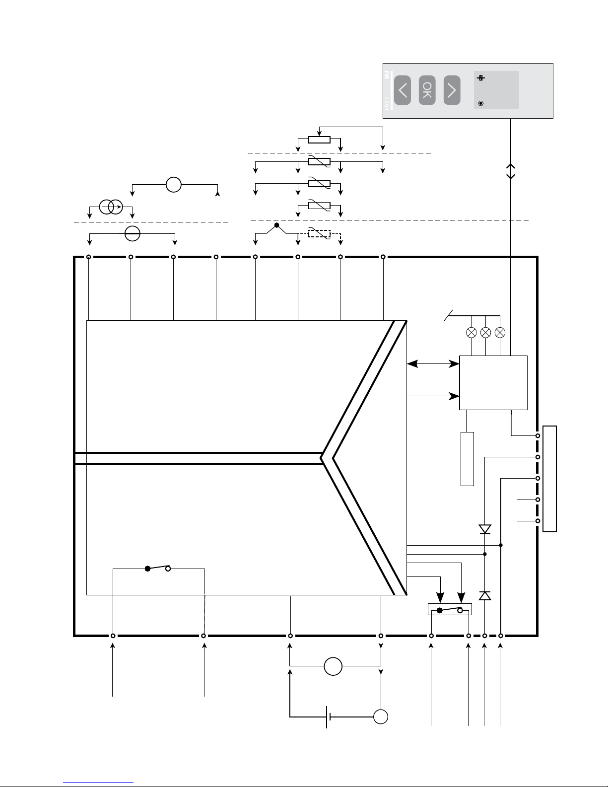
9116
51
31
14
32
34
33
12
11
13
54
53
52
44
43
42
41
NC*NC*
+24V
CPU
FLASH
I
o20 mA
I
800.0
1
+
-
+
-
Tx
4
3
2
*
+
-
I+
mA
mA
+
-
50 9116 - Product Version 9116-001
BLOCK DIAGRAM
Device status,
Green
Relay status, Yellow
Ch. status, Red
Status relay N.C.
Status relay N.C.
Gnd.
Supply +24 VDC
Relay N.O.
Relay N.O.
Gnd.
Power Rail connections
Input
RTD, conn.
wires
Potentiometer
TC
Volt-
age
Current
mA
output
Supply
Relay
output
* NC = no connection
Page 53
9116 - Product Version 9116-001 51
List of LED and error signal indications
Condition Green LED
Relay:
Yellow LED
Error:
Red LED
Status relay,
N.C.
Power rail
signal status
No supply OFF OFF OFF De-energized Closed
Device failure OFF ON De-energized Closed
Device OK Flashing Energized Open
Signal OK Flashing OFF Energized Open
Output relay energized Flashing ON OFF Energized Open
Output relay energized w. wire short/break Flashing ON Flashing De-energized Closed (if enabled)
Output relay de-energized w. wire short/break Flashing OFF Flashing De-energized Closed (if enabled)
Output relay de-Energized Flashing OFF OFF Energized Open
Signal error and cable fault indications without display front
Page 54

52 9116 - Product Version 9116-001
CONFIGURATION /
OPERATING THE FUNCTION KEYS
Documentation for routing diagram.
In general
When configuring the 9116, you will be guided through all parameters and you
can choose the settings which fit the application. For each menu there is a
scrolling help text which is automatically shown in line 3 on the display.
Configuration is carried out by use of the 3 function keys:
1 will increase the numerical value or choose the next parameter
2 will decrease the numerical value or choose the previous parameter
3 will accept the chosen value and proceed to the next menu
When configuration is completed, the display will return to the default state 1.0.
Pressing and holding
3 will return to the previous menu or return to the default
state (1.0) without saving the changed values or parameters.
If no key is activated for 1 minute, the display will return to the default state
(1.0) without saving the changed values or parameters.
Further explanations
Password protection: Programming access can be blocked by assigning a
password. The password is saved in the converter in order to ensure a high
degree of protection against unauthorised modifications to the configuration.
Default password 2008 allows access to all configuration menus. Password
protection is mandatory in SIL applications.
Selection of units
After choosing the input signal type you can choose which process units should
be shown in the display (see table). By selection of temperature input the
process value is always displayed in Celsius or Fahrenheit. This is selected in
the menu point after selection of temperature input.
CJC
In the CJC menu you can choose between CJC connector and internal cold
junction compensation. The CJC connecter (PR 5910Ex) must be ordered
separately.
Page 55

9116 - Product Version 9116-001 53
Signal and sensor error information via display front 4501
Sensor error (see limits in the table) is displayed as SE.BR (sensor break) or
SE.SH (sensor short). Signals outside the selected range (not sensor error,
see table for limits) are displayed as IN.LO indicating low input signal or IN.HI
indicating high input signal. The error indication is displayed as text in line 1
and at the same time the backlight flashes. Line 4 of the display is a status
line which shows whether the device is SIL-locked (static dot = SIL-locked
and flashing dot = not SIL-locked) as well as relay status and COM (running
circle) indicating correct functioning of 4501.
Signal and sensor error indication without display front
Status of the unit can also be read from the 3 LEDs in the front of the device.
Green flashing LED indicates normal operation.
No light in the green LED indicates lack of supply voltage or error in the device.
Steady red LED indicates fatal error.
Flashing red LED indicates sensor error.
Relay functions
5 different settings of relay function can be selected.
Setpoint: The unit works as a single trip amplifier
Window: The relay has a window that is defined by a low and a high set -
point. On both sides of the window the relay has the same status.
Error function: The relay is activated by sensor error.
Power: The relay is activated as long as the power is on.
Off: The relay is deactivated.
Increasing/decreasing: The relay can be set to activate at increasing or
decreasing input signal.
Delay: An ON and an OFF delay can be set in the range 0...3600 s.
Hysteresis: A hysteresis can be set at 0.1...25% of the span or between 1 and
25% of display range.
Window: The window function is selected by choosing ”window” in the menu
and defining a high and a low setpoint.
See the graphic depiction of the window functions on page 62.
Setpoint: The setpoint function is selected by choosing ”setpoint” in the menu
and entering the desired limit. The device then works as a single limit switch.
See the graphic depiction of the window functions on page 63.
Page 56

54 9116 - Product Version 9116-001
An activated relay means that the contact is closed if the contact function
”normally open” is selected, and the contact is open if the contact function
”normally closed” is selected.
The delay time for activation and deactivation can be set independently of each
other in the menus ON.DEL and OFF DEL respectively.
Advanced functions
The unit gives access to a number of advanced functions which can be reached
by answering “Yes” to the point “adv.set”.
Display setup: Here you can adjust the brightness contrast and the backlight.
Setup of TAG numbers with 5 alphanumerics. Input value is always shown in
line 2. Selection of functional readout in line 3 of the display - choose between
readout of analogue output or tag no or alternating display.
Two-point process calibration: The device can be process-calibrated in 2
points to fit a given input signal . A low input signal (not necessarily 0%)
is applied and the actual value is entered via 4501. Then a high signal (not
necessarily 100%) is applied and the actual value is entered via 4501. If you
accept to use the calibration, the device will work according to this new
adjustment. If you later reject this menu point or choose another type of input
signal the device will return to factory calibration.
Process simulation function: In the menu point “EN.SIM” it is possible to
simulate an input signal by means of the arrow keys and thus control the
output signal up or down, or the relay state OFF and ON . You must exit the
menu by pressing 3 (no time-out). The simulation function exits automatically,
if the 4501 is detached.
Password: Here you can choose a pass word between 0000 and 9999 in order
to protect the device against unauthorised modifications to the configuration.
The device is delivered default without password.
Memory: In the memory menu you can save the configuration of the device in
the 4501, and then move the 4501 onto another device of the same type and
download the configuration in the new device.
Page 57

9116 - Product Version 9116-001 55
Language: In the menu ”lang.setup” you can choose between 7 different
language versions of help texts that will appear in the menu. You can choose
between UK, DE, FR, IT, ES, SE and DK.
Power rail: In the menu ”RAIL” you can choose if sensor errors are transmitted
to the central surveillance in the PR 9410 power control unit.
Safety integrity level: See Safety Manual for details
Page 58
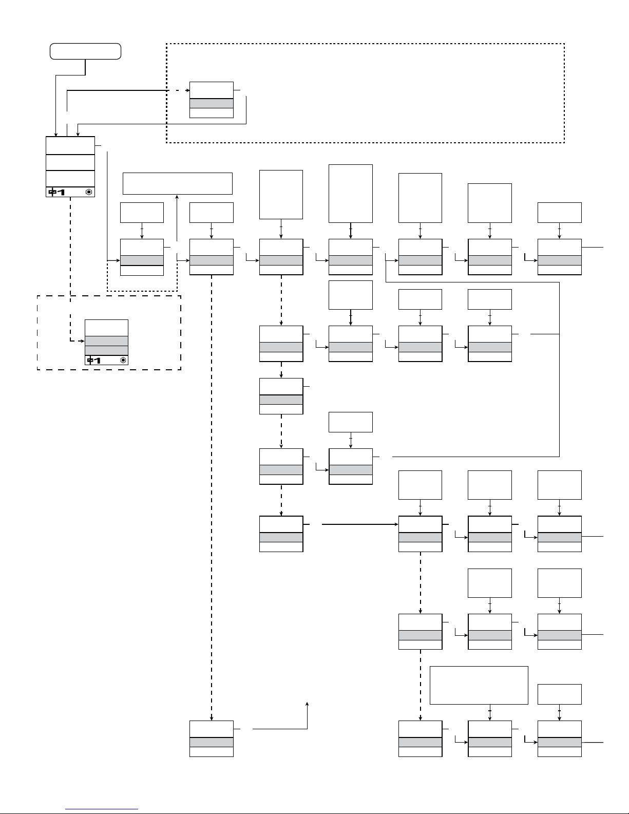
1
0000
PASSW.
Txt 1
Io12.00mA
3
3
0000
9999
1 2
NO
ADV.SET
Txt 2
NO
YES
1 2
3
VOLT
IN TYPE
Txt 3
VOLT
LIN.R
POTM
CURR
TEMP
1 2
3
50.0
SETP.
Txt 57
3
1 2
2-10
V.RANGE
Txt 4
2-10
0-10
1-5
0-5
0.2-1
0-1
1 2
3
TEMP
IN TYPE
Txt 3
3
Pt
SENSOR
Txt 10
Pt
NI
TC
1 2
3
YES
ADV.SET
3
Ni
SENSOR
Txt 10
3
TC
SENSOR
3
100
Pt TYPE
Txt 16
1000
-
10
1 2
3
3W
CONNEC.
Txt 6
4W
3W
2W
1 2
100
Ni TYPE
Txt 17
1000
-
50
1 2
TC.K
TC.TYPE
TC.B TC.E TC.J TC.K
TC.L TC.N TC.R TC.S
TC.T TC.U TC.W3
TC.W5 TC.Lr
1 2
0.0
DISP.LO
Txt 13
999.9
-199.9
1 2
111.1
DEC.P
Txt 12
1111
111.1
11.11
1.111
1 2
3
UNIT
%
Txt 11
@C
mA
rpm
(70 units)
1 2
3
CURR
IN TYPE
Txt 3
3
4-20
I.RANGE
Txt 5
0-20
4-20
1 2
3
LIN.R
IN TYPE
Txt 3
3
3W
CONNEC.
Txt 6
4W
3W
2W
1 2
3
POTM
IN TYPE
Txt 3
3
0
R 0%
Txt 7
0000
9999
1 2
3
0
R 100%
Txt 8
0000
9999
1 2
3
1.0
1.2
1.1
3
3W
CONNEC.
Txt 6
4W
3W
2W
1 2
3
3W
CONNEC.
Txt 6
4W
3W
2W
1 2
3
CJC
INT
CONN
1 231 2
SE.BR
o3.50mA
INT
I
I
30.00
Txt 2 Txt 10 Txt 18 Txt 31
Power up
56 9116 - Product Version 9116-001
Continued on the page
Routing diagram ADV.SET
Fast setpoint adjustment
and relay test
1 Increase setpoint
2 Decrease setpoint
3 Save and exit the menu
1 and 2 simultaneously = change relay state
Error indication, example
If SIL-locked
directly to EN.SIL]
Red text signifies safety
parameters in a SIL
configuration. See safety
manual for details
Page 59
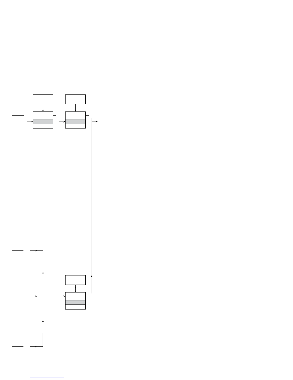
@C
@F
K
%
m
cm
mm
um
ft
in
mils
yd
m3
l
s
min
m/s
mm/s
m/min
m/h
in/s
ips
ft/s
in/min
ft/min
in/h
ft/h
m/s2
rpm
Hz
t
kg
g
N
Pa
MPa
kPa
hPa
bar
mbar
kj
Wh
MWh
kWh
W
GW
MW
kW
hp
A
kA
mA
uA
V
kV
mV
ohm
S
uS
m3/min
m3/h
l/s
l/min
l/h
gal/min
gal/h
t/h
mol
pH
[blank]
Txt 9
3
100.0
DISP.HI
Txt 14
999.9
-199.9
1 2
3
DISP
REL.UNI
Txt 15
DISP
PERC
1 2
@C
UNIT
@C
@F
1 2
3
3
3
3
3
9116 - Product Version 9116-001 57
1.0 = Default state. Line 1 shows
input status. Line 2 shows
input value and TAG NO.
Line 3 shows output value
and units. Line 4 shows
status for relay and commu nication and whether the
device is SIL-locked. Static
dot = SIL-locked and
flashing dot = not SIL locked.
1.1 = Only if password-protected.
1.2 = Only if FastSet is activated
and the relay function is
setpoint.
1.3 = Only if input types support
sensor error check.
Not valid for these input
signals: 0...20 mA and
voltage.
1.4 = Only if input signal is
temperaure.
1.5 = Only if the configuration is
not protected by a pass word.
Continued on the next page
ROUTING DIAGRAM
If no key is activated for 1 minute, the display will return to the default state 1.0
without saving configuration changes.
1 Increase value / choose next parameter
2 Decrease value / choose previous parameter
3 Accept the chosen value and proceed to the next menu
Hold 3 Back to previous menu / return to menu 1.0 without saving
Selectable
UNITS:
Page 60
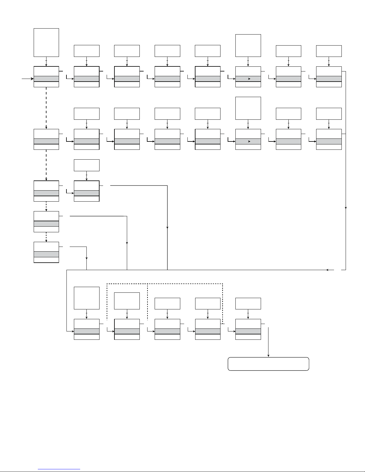
0
ON.DEL
Txt 25
3600
0000
1 2
NONE
ERR.ACT
Txt 24
HOLD
CLOS
OPEN
NONE
1 2
3
0
OFF.DEL
Txt 26
3600
0000
1 2
3
0
ON.DEL
Txt 25
3600
0000
1 2
NONE
ERR.ACT
Txt 24
HOLD
CLOS
OPEN
NONE
1 2
3
0
OFF.DEL
Txt 26
3600
0000
1 2
3
3
1.3
1.3
4-20
O.RANGE
Txt 37
20-4
20-0
4-20
0-20
1 2
3
23mA
OUT.ERR
Txt 38
23mA
0/3.5mA
NONE
1 2
3
0.0
OUT.LO
Txt 41
849
-200
1 2
3
150.0
OUT.HI
Txt 42
850.0
-199.0
1 2
1.3
1.4 1.4
3
0.0
RESP.
Txt 39
0.0
60
1 2
N.O.
CONTAC
Txt 20
3
N.O.
N.C.
1 2
50.0
SETP.
Txt 21
850
-200
1 2
3
INCR
ACT.DIR
Txt 22
INCR
DECR
1 2
3
1.0
HYST.
Txt 23
262.5
0.1
1 2
SETP
REL.FUN
Txt 19
SETP
WIND
ERR
POW
OFF
1 2
3
O.I.W
CONTAC
Txt 27
3
O.I.W
C.I.W
1 2
50.0
SETP.LO
Txt 28
849.9
-200
1 2
3
60.0
SETP.HI
Txt 28
850.0
-199.9
1 2
3
1.0
HYST.
Txt 30
262.5
0.1
1 2
WIND
REL.FUN
Txt 19
3
OPEN
ERR.ACT
Txt 34
3
CLOS
OPEN
1 2
ERR
REL.FUN
Txt 19
3
POW
REL.FUN
Txt 19
OFF
REL.FUN
Txt 19
3
3
1.3
3
3
3
58 9116 - Product Version 9116-001
To default state 1.0
Page 61
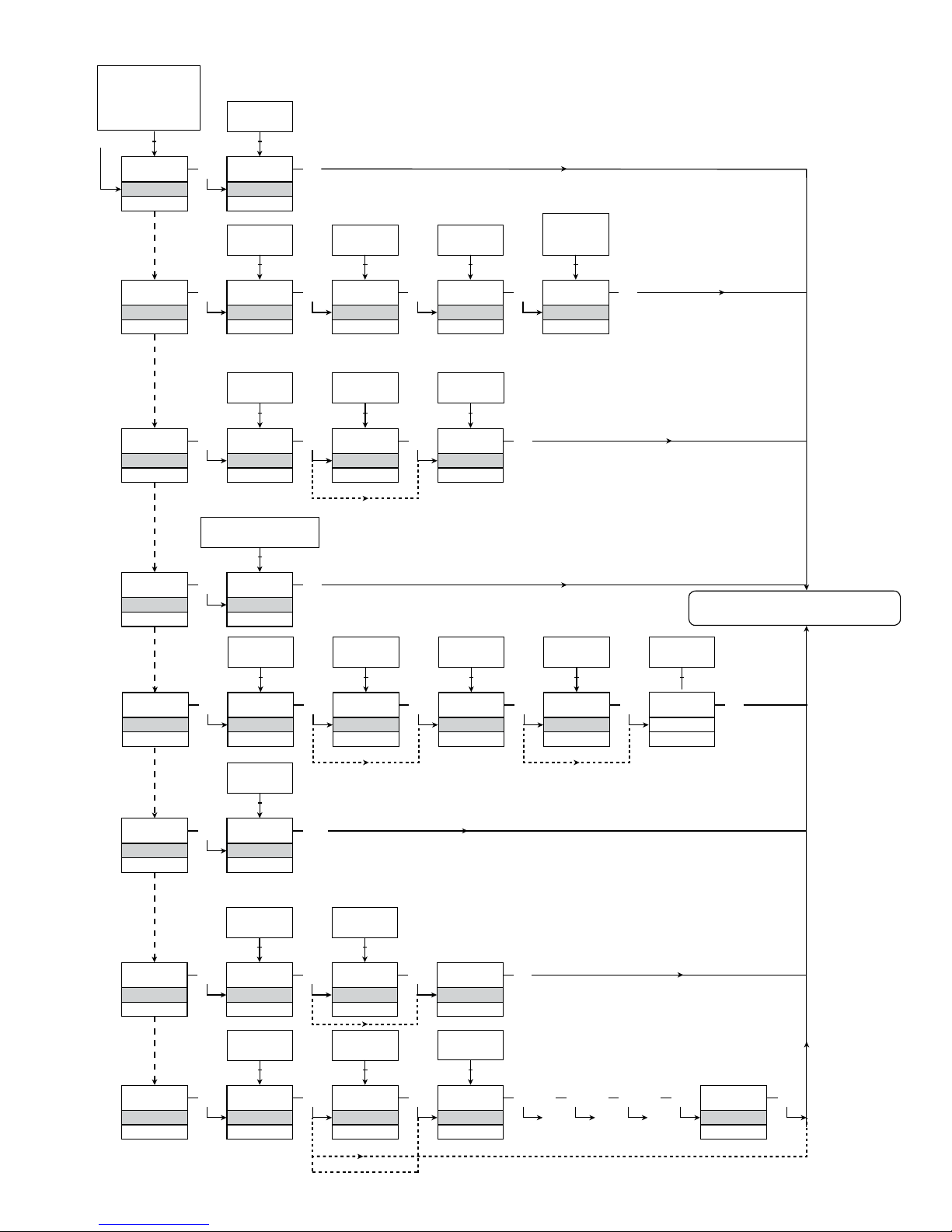
SAVE
MEMORY
Txt 44
3
SAVE
LOAD
1 2
MEM
SETUP
Txt 43
MEM, DISP,
PASS, LANG,
CAL, RAIL,
SIM, SIL
1 2
3
DISP
SETUP
Txt 43
3
3
CONTRA
Txt 45
3
9
0
1 2
9
LIGHT
Txt 46
3
9
0
1 2
TAG.1
TAGNO
Txt 47
3
9
A
1 2
A.OUT
DISP
Txt 48
3
TAG
ALT
A.OUT
1 2
CAL
SETUP
Txt 43
3
YES
CAL.LO
Txt 49
3
YES
NO
1 2
2.0
@C
Txt 61
3
850.0
-200.0
1 2
NO
YES
CAL.HI
Txt 50
3
YES
NO
1 2
147.8
@C
Txt 62
3
850.0
-200.0
1 2
NO
3
USE.CAL
Txt 60
YES
NO
1 2
SIM
SETUP
Txt 43
3
YES
EN.SIM
Txt 51
3
YES
NO
1 2
23.0
%
Txt 52
3
850.0
-200.0
1 2
NO
REL.SIM
Txt 53
3
2.0
RAIL
SETUP
Txt 43
3
YES
RAIL.ER
Txt 63
3
YES
NO
1 2
SIL
SETUP
Txt 43
3
YES
EN.SIL
Txt 64
YES
NO
1 2
NO
3
2008
NEW.PAS
Txt 55
0000
9999
1 2
3
LOCK
CONFIG
Txt 66
SIL.OK
. . . . . . . . . . . . . .
3 3 3 3 3
OPEN
LOCK
1 2
LANG
SETUP
Txt 43
3
UK
LANGUA
Txt 59
3
DE, DK, ES, FR,
IT, SE, UK
1 2
PASS
SETUP
Txt 43
3 3
YES
EN.PASS
Txt 54
3
YES
NO
1 2
NO
0000
NEW.PAS
Txt 55
3
9999
0000
1 2
YES
EN.FAST
Txt 56
YES
NO
1 2
3
YES
1.4
9116 - Product Version 9116-001 59
ROUTING DIAGRAM
ADVANCED SETTINGS (ADV.SET)
To default state 1.0
Verify SIL configuration
2.0 In the submenu simulation (SIM) you must
press 3 to return to the default state 1.0.
Page 62

60 9116 - Product Version 9116-001
SCROLLING HELP TEXTS IN DISPLAY LINE 3
[01]
[02]
[03]
[04]
[05]
[06]
[07]
[08]
[09]
[10]
[11]
[12]
[13]
[14]
[15]
[16]
[17]
[18]
[19]
[20]
[21]
[22]
[23]
[24]
[25]
[26]
[27]
[28]
[29]
[30]
[31]
[34]
[37]
[38]
[39]
[41]
[42]
[43]
[44]
[45]
[46]
[47]
[48]
[49]
[50]
[51]
[52]
[53]
[54]
[55]
[56]
[57]
[58]
[59]
[60]
[61]
[62]
[63]
[64]
Set correct password
Enter Advanced setup menu?
Select Temperature input
Select Potentiometer input
Select Linear resistance input
Select Current input
Select Voltage input
Select 0.0-1 V input range
Select 0.2-1 V input range
Select 0-5 V input range
Select 1-5 V input range
Select 0-10 V input range
Select 2-10 V input range
Select 0-20 mA input range
Select 4-20 mA input range
Select 2-Wire sensor connection
Select 3-Wire sensor connection
Select 4-Wire sensor connection
Set Resistance value low
Set Resistance value high
Select Celsius as temperature unit
Select Fahrenheit as temperature unit
Select TC sensor type
Select Ni sensor type
Select Pt sensor type
Select Display unit
Select Decimal point position
Set Display range low
Set Display range high
Select Relay setpoint in % of input range
Select Relay setpoint in display units
Select Pt10 sensor type
Select Pt20 sensor type
Select Pt50 sensor type
Select Pt100 sensor type
Select Pt200 sensor type
Select Pt250 sensor type
Select Pt300 sensor type
Select Pt400 sensor type
Select Pt500 sensor type
Select Pt1000 sensor type
Select Ni50 sensor type
Select Ni100 sensor type
Select Ni120 sensor type
Select Ni1000 sensor type
Select TC-B sensor type
Select TC-E sensor type
Select TC-J sensor type
Select TC-K sensor type
Select TC-L sensor type
Select TC-N sensor type
Select TC-R sensor type
Select TC-S sensor type
Select TC-T sensor type
Select TC-U sensor type
Select TC-W3 sensor type
Select TC-W5 sensor type
Select TC-Lr sensor type
Select OFF function - relay is permanently off
Select POWER function - relay indicates power status OK
Select ERROR function - relay indicates sensor error only
Select WINDOW function - relay is controlled by 2 setpoints
Select SETPOINT function - relay is controlled by 1 setpoint
Select Normally Closed contact
Select Normally Open contact
Set Relay setpoint
Select Action on decreasing signal
Select Action on increasing signal
Set Relay hysteresis
Select No error action - undefined status at error
Select Open relay contact at error
Select Close relay contact at error
Select Hold relay status at error
Set Relay ON delay in seconds
Set Relay OFF delay in seconds
Select Contact is Closed Inside Window
Select Contact is Open Inside Window
Set Relay window setpoint low
Set Relay window setpoint high
Set Relay window hysteresis
Select Internal temperature sensor
Select CJC connector (Accessory)
Select Open relay contact at error
Select Close relay contact at error
Select 0-20 mA outout range
Select 4-20 mA output range
Select 20-0 mA output range
Select 20-4 mA output range
Select No error action - output undefined at error
Select Downscale at error
Select Namur NE43 downscale at error
Select Namur NE43 upscale at error
Select Analogue output response time in seconds.
Set Temperature for analogue output low
Set Temperature for analogue output high
Enter SIL setup
Enter Simulation mode
Enter Rail setup
Perform Process Calibration
Enter Language setup
Enter Password setup
Enter Display setup
Perform Memory operations
Load saved configuration into module
Save configuration in display front
Adjust LCD contrast
Adjust LCD backlight
Write a 5-character channel TAG
Show Analog output value in display
Show TAG on display
Alternate shown information in display
Calibrate Input low to process value?
Calibrate Input high to process value?
Enable input simulation?
Set the input simulation value
Relay simulation - use 1 to toggle relay
Enable Password protection?
Set New password
Enable Fastset functionality?
Relay setpoint - press 3 to save
Relay setpoint - Read only
Select Language
Use process calibration values?
Set value for low calibration point
Set value for high calibration point
Enable Rail status signal output?
Enable SIL configuration lock?
0...20 mA is not a valid output range for SIL
operation
Page 63

9116 - Product Version 9116-001 61
[65]
[66]
[80]
[81]
[82]
[83]
[84]
[85]
[86]
[87]
[88]
[89]
[90]
[91]
[92]
[93]
is channel using process-compensated calibration
data?
Configuration SIL status (Open / Locked)
Sensor short circuit
Sensor wire breakage
Display underrange
Display overrange
Input underrange
Input overrange
Input error - check input connections and reset
power
Output error - check connentions and reset power
Flash memory error - chek configuration
Invalid configuration type or version
Hardware error
CJC sensor error - check device temperature
CJC error - check CJC connector block
No communication
Page 64
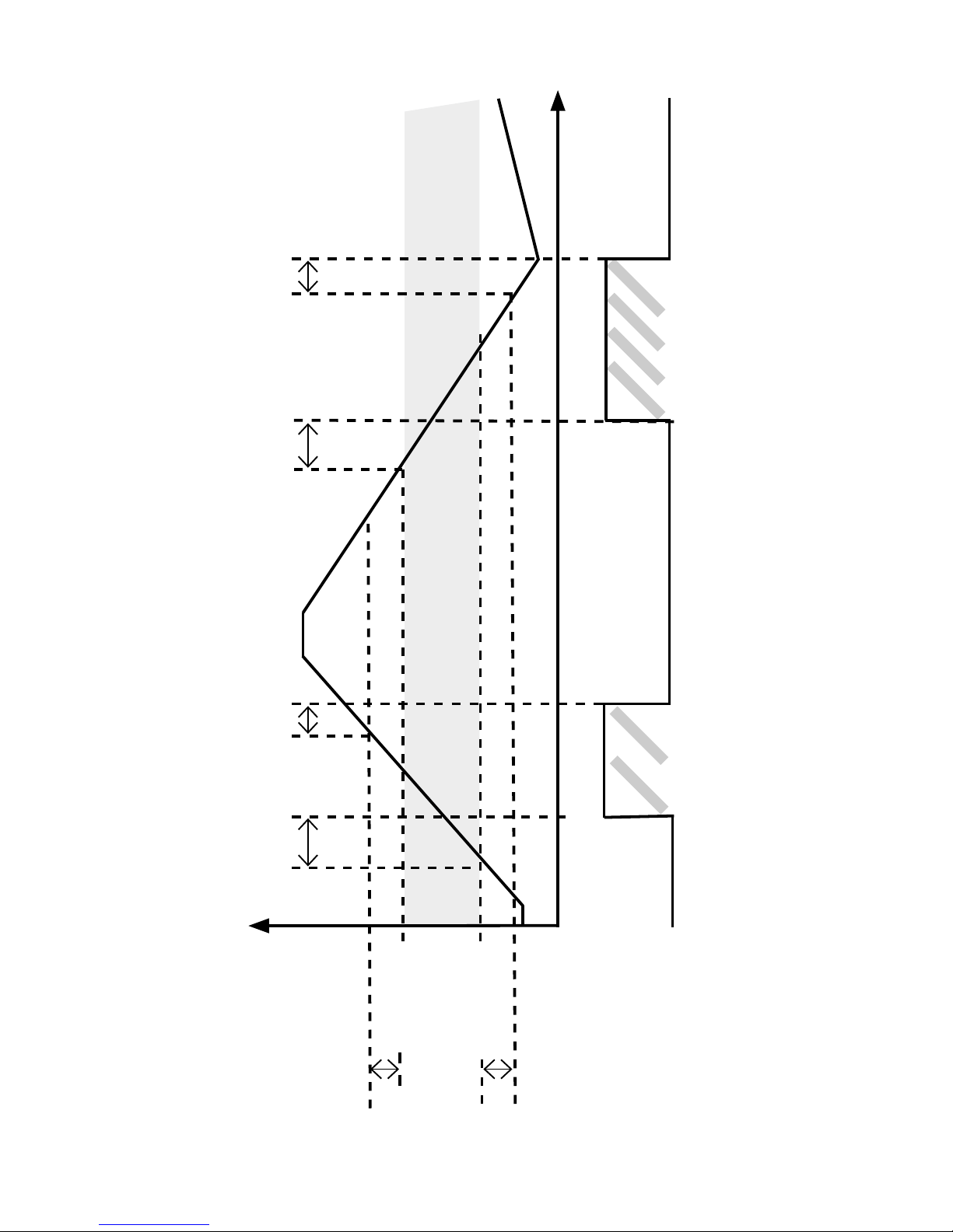
62 9116 - Product Version 9116-001
Graphic depiction of window
Hysteresis
Setpoint high
ON delay OFF delay
Relay On Relay On
Closed
Open
Relay contact (N.O.)
Time
Window
ON delay OFF- delay
Hysteresis
Setpoint low
Page 65
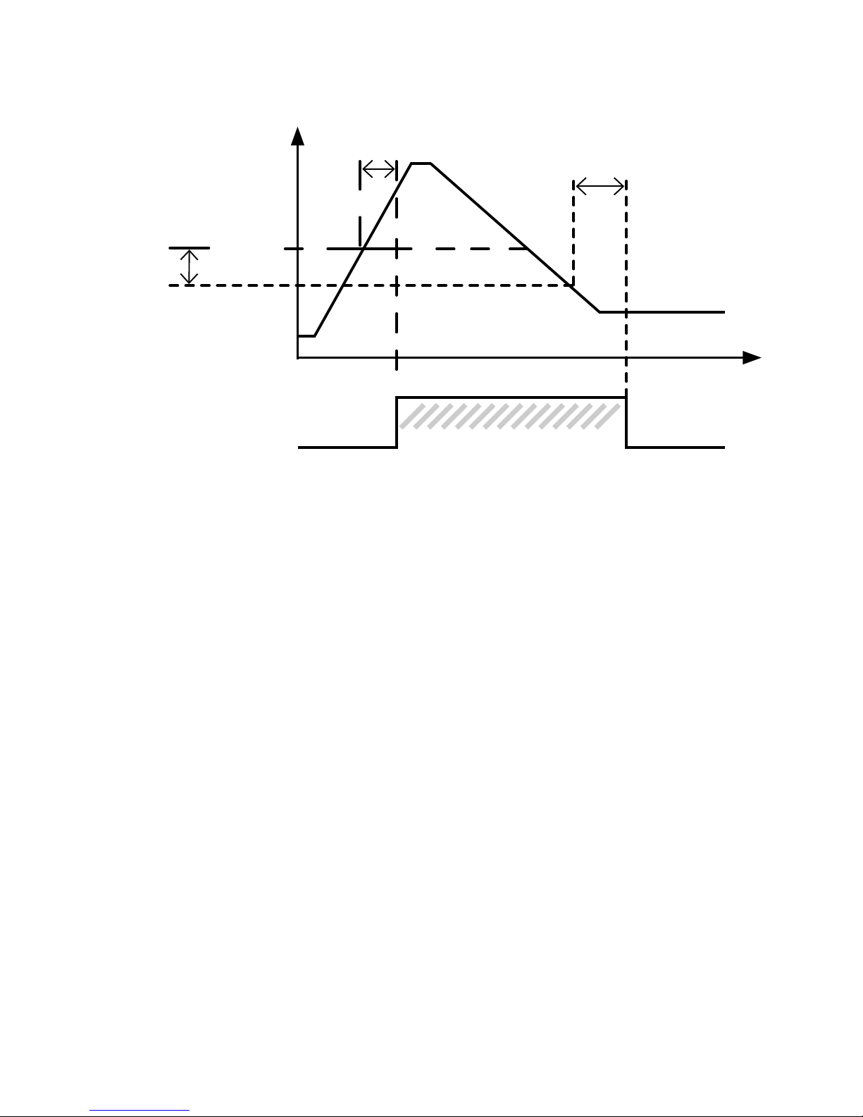
9116 - Product Version 9116-001 63
Graphic depiction of setpoint
Relay On
OFF delay
ON delay
Input
signal
Hysteresis
Setpoint
(increasing)
Time
Closed
Open
Relay contact
(N.O.)
Page 66

64 9116 - Product Version 9116-001
Page 67

9116 - Product Version 9116-001 65
CONVERTISSEUR PROGRAMMABLE
À SEUILS, [Ex ia]
9116
SOMMAIRE
Avertissement ................................................................................. 66
Consignes de sécurité.................................................................... 66
Démontage du système 9000 ........................................................ 68
Déclaration de conformité CE ........................................................ 69
Options avancées........................................................................... 70
Fonctions ........................................................................................ 70
Caractéristiques techniques........................................................... 70
Applications .................................................................................... 71
PR 4501 indicateur / façade de programmation............................ 72
Références de commande ............................................................. 73
Spécifications ................................................................................. 73
Configuration du contrôle d’erreur de câble .................................. 77
Indication dans le 4501 de
Signal d’entrée hors d’échelle ................................................... 78
Détection erreur capteur ............................................................ 78
Indications erreur matériel ......................................................... 79
Connexions .................................................................................... 81
Schéma de principe ....................................................................... 82
Indications d’erreur signal et câble sans la façade 4501 .............. 83
Programmation / opération des touches de fonction .................... 84
Diagramme de programmation ...................................................... 89
Diagramme de programmation, Réglage avancé (ADV.SET) ......... 91
Menu déroulant en ligne 3 de l’indicateur...................................... 92
Graphique descriptif de la fonction fenêtre ................................... 94
Graphique descriptif de la fonction consigne ................................ 95
Appendix ........................................................................................ 128
IECEx Installation Drawing......................................................... 129
ATEX Installation Drawings, UK, FR, DE, DK ............................ 133
FM Installation Drawing ............................................................. 149
Safety Manual ............................................................................ 153
Page 68
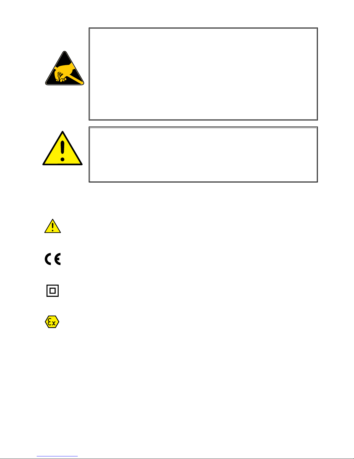
66 9116 - Product Version 9116-001
SIGNIFICATION DES SYMBOLES
Triangle avec point d’exclamation : Attention ! Lire ce manuel avant
l’installation et la mise en service de ce module afin d’éviter des incidents
pouvant causer des dommages corporels ou des dégâts mécaniques.
Le signe CE indique que le module est conforme aux exigences des
directives.
Ce symbole indique que le module est protégé par une isolation double
ou renforcée.
L’utilisation des modules de type Ex avec des installations situées dans
des zones à risques d’explosions a été autorisée suivant la directive ATEX.
Voir le schéma d’installation dans les annexes.
CONSIGNES DE SECURITE
DEFINITIONS
Les gammes de tensions dangereuses sont les suivantes : de 75 à 1500 Vcc
et de 50 à 1000 Vca.
Les techniciens sont des personnes qualifiées qui sont capables de monter et
de faire fonctionner un appareil, et d’y rechercher les pannes, tout en respectant
les règles de sécurité.
AVERTISSEMENT
Les opérations suivantes doivent être effectuées avec le module
débranché et dans un environnement exempt de décharges
électrostatiques (ESD) :
Montage général, raccordement et débranchement de fils.
Recherche de pannes sur le module.
Seule PR electronics SARL est autorisée à réparer le module
et à remplacer les fusibles.
AVERTISSEMENT
Ne pas ouvrir la plaque avant du module au risque d’endommager
le connecteur de l’indicateur / la façade de programmation PR
4501. Ce module ne contient ni de commutateurs DIP ni de
cavaliers.
Page 69

9116 - Product Version 9116-001 67
Les opérateurs, connaissant le contenu de ce guide, règlent et actionnent les
boutons ou les potentiomètres au cours des manipulations ordinaires.
RECEPTION ET DEBALLAGE
Déballez le module sans l’endommager. Il est recommandé de conserver
l’emballage du module tant que ce dernier n’est pas définitivement monté. A la
réception du module, vérifiez que le type de module reçu correspond à celui que
vous avez commandé.
ENVIRONNEMENT
N’exposez pas votre module aux rayons directs du soleil et choisissez un endroit
à l’humidité modérée et à l’abri de la poussière, des températures élevées, des
chocs et des vibrations mécaniques et de la pluie. Le cas échéant, des systèmes
de ventilation permettent d’éviter qu’une pièce soit chauffée au-delà des limites
prescrites pour les températures ambiantes.
Ce module doit être installé en degré de pollution 2 ou meilleur.
Ce module est conçu pour fonctionner en toute sécurité sous une altitude
inférieure à 2000 m.
MONTAGE
Il est conseillé de réserver le raccordement du module aux techniciens qui
connaissent les termes techniques, les avertissements et les instructions de ce
guide et qui sont capables d’appliquer ces dernières.
Si vous avez un doute quelconque quant à la manipulation du module, veuillez
contacter votre distributeur local. Vous pouvez également vous adresser à
PR electronics SARL, Zac du Chêne, Activillage, 4, allée des Sorbiers,
F-69673 Bron Cedex (tél. : (0) 472 140 607) ou à
PR electronics A/S, Lerbakken 10, DK-8410 Rønde, Danemark (tél. : +45 86 37 26 77).
Pour le raccordement électrique de l’alimentation générale, il est possible
d’utiliser des fils multibrins seulement s’ils possèdent des embouts de câblage.
Les connexions des alimentations et des entrées / sorties sont décrites dans le
schéma de principe et sur l’étiquette de la face latérale du module.
Les appareils sont équipés de borniers à vis et doivent être raccordés à une
alimentation qui a une isolation double ou renforcée. L’interrupteur doit être
à proximité du module et facile d’accès. Ce bouton doit être étiqueté avec la
mention : peut couper la tension du module.
Pour une installation sur le rail d’alimentation 9400, le module sera alimenté par
le contrôleur d’alimentation 9410.
Page 70
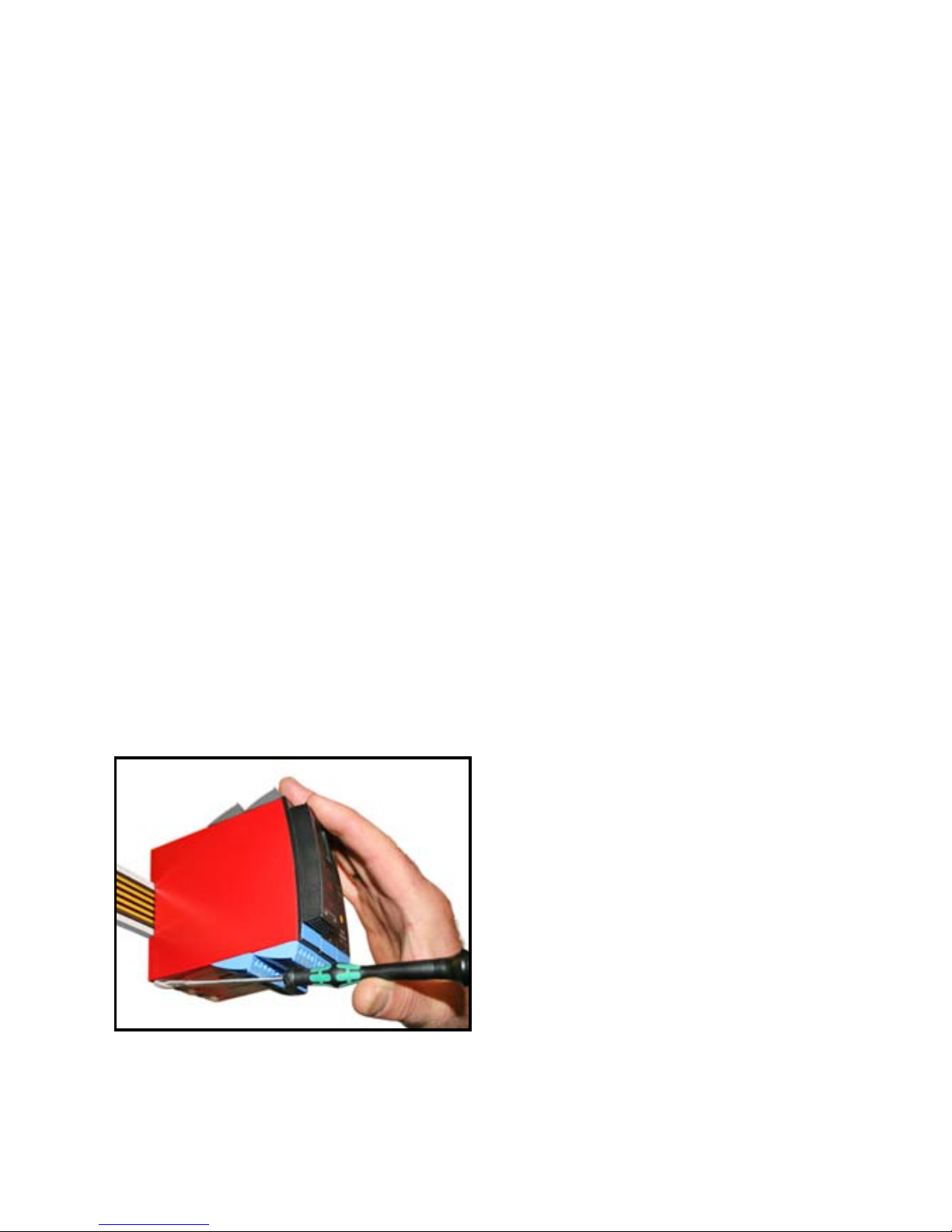
68 9116 - Product Version 9116-001
L’année de production est définie par les deux premiers chiffres du numéro de
série.
ETALONNAGE ET REGLAGE
Lors des opérations d’étalonnage et de réglage, il convient d’effectuer les
mesures et les connexions des tensions externes en respectant les spécifications
mentionnées dans ce guide. Les techniciens doivent utiliser des outils et des
instruments pouvant être manipulés en toute sécurité.
MANIPULATIONS ORDINAIRES
Les opérateurs sont uniquement autorisés à régler et faire fonctionner des
modules qui sont solidement fixés sur des platines des tableaux, ect., afin
d’écarter les risques de dommages corporels. Autrement dit, il ne doit exister
aucun danger d’électrocution et le module doit être facilement accessible.
MAINTENANCE ET ENTRETIEN
Une fois le module hors tension, prenez un chiffon imbibé d’eau distillée pour
le nettoyer.
LIMITATION DE RESPONSABILITE
Dans la mesure où les instructions de ce guide ne sont pas strictement
respectées par le client, ce dernier n’est pas en droit de faire une réclamation
auprès de PR electronics SARL, même si cette dernière figure dans l’accord de
vente conclu.
DEMONTAGE DU SYSTEME 9000
Figure 1 :
Débloquez le verrou inférieur
pour dégager le module du rail
d’alimentation.
Page 71

9116 - Product Version 9116-001 69
DECLARATION DE CONFORMITE CE
En tant que fabricant
PR electronics A/S
Lerbakken 10
DK-8410 Rønde
déclare que le produit suivant :
Type : 9116
Nom : Convertisseur programmable à seuils, [Ex ia]
correspond aux directives et normes suivantes :
La directive CEM (EMC) 2004/108/CE et les modifications subséquentes
EN 61326-1 : 2006
Pour une spécification du niveau de rendement acceptable CEM (EMC)
se référer aux spécifications électriques du module.
La directive basse tension 2006/95/CE et les modifications subséquentes
EN 61010-1 : 2001
La directive ATEX 94/9/CE et les modifications subséquentes
EN 61241-0 : 2006, EN 61241-11 : 2006, EN 60079-0 : 2006,
EN 60079-11 : 2007, EN 60079-15 : 2005, EN 60079-26 : 2007
Certificat ATEX : KEMA 07ATEX0149 X
Organisme notifié :
KEMA Quality B.V. (0344)
Utrechtseweg 310, 6812 AR Arnhem
P.O. Box 5185, 6802 ED Arnhem
The Netherlands
Rønde, le 15 janvier 2010 Kim Rasmussen
Signature du fabricant
Page 72

70 9116 - Product Version 9116-001
CONVERTISSEUR PROGRAMMABLE À SEUILS, [Ex ia]
9116
• Entrées : Pt100, TC, Ohm, potentiomètre, mA et V
• Alimentation pour transmetteurs 2-fils
• Sortie mA active / passive et sortie relais
• Alimenté séparément ou par le rail d’alimentation, type 9400
• Certifié SIL 2 en « Evaluation Complète »
Options avancées
• Programmation et contrôle à l’aide de la façade de programmation (4501);
calibration de process et simulation de signaux et de relais.
• Configuration avancée du relais, p.ex. consigne, fenêtre, délai, détection
erreur capteur et surveillance de l’alimentation.
• Recopie de la configuration d’un module à d’autres du même type à l’aide de
la façade de programmation.
• Caractéristiques S.I. d’Uo réduites à < 8,3 V pour des signaux d’entrée actives.
• Les entrées TC peuvent utiliser soit la CSF interne soit le bornier avec
capteur Pt100 incorporé (PR 5910Ex, voie 1 / PR 5913Ex, voie 2) pour une
précision améliorée.
• Le 9116 détecte automatiquement s’il doit fournir un signal de courant actif
ou passif.
Fonctions
• Le module peut être installé dans la zone non-dangereuse et en zone 2/div. 2 et
recevoir des signaux de la zone 0, 1, 2, 20, 21 et 22 / Class I/II/III, Div. 1, Gr. A-G.
• Conversion et mise à l’échelle de signaux en température, en tension,
potentiométriques et de résistance linéaire.
• Alimentation et isolateur de signaux pour transmetteurs 2-fils.
• Surveillance de cas d’erreurs internes rupture câble par le relais d’état
individuel et / ou un signal électronique collectif par le rail d’alimentation.
• Le 9116 a été conçu, développé et certifié pour utilisation dans les
applications SIL 2 en conformité avec les exigences de la CEI 61508.
Caractéristiques techniques
• 1 LED verte et 2 LED rouges en face avant indiquent un fonctionnement
normal ou incorrect du module. 1 LED jaune indique l’état du relais.
• Isolation galvanique de 2,6 kVca entre l’entrée, la sortie et l’alimentation.
Page 73
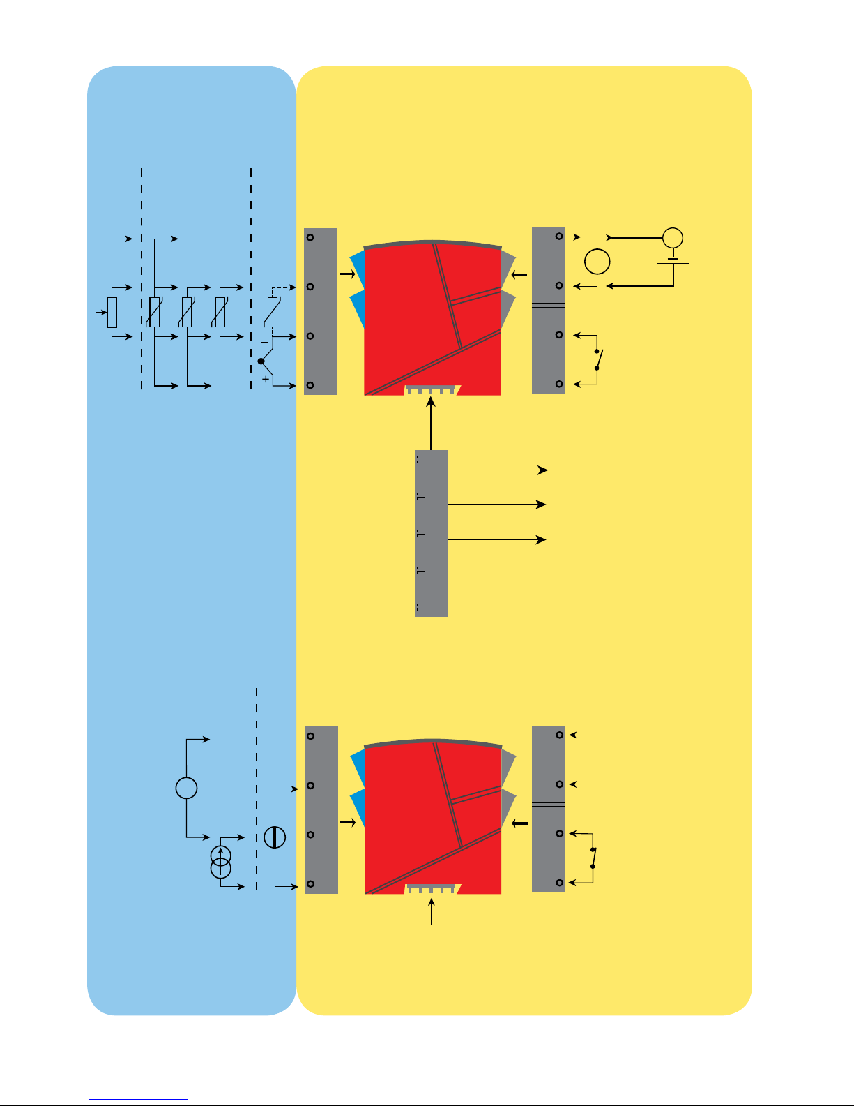
*
+
-
mA
mA
+
44
43
42
41
12
11
14
13
+
+
+
-
Tx
54
53
52
51
31
32
33
34
9116 - Product Version 9116-001 71
APPLICATIONS
Signaux d’entrée :
Poten-
tiomètre
TC
Pt100 et R lin.
Connexion, fils
Analogique, 0/4...20 mA et relais
Relais
Relais
N.O.
Rail, +24 Vcc
Rail, masse
Rail
d’alimentation
Signal du relais d’état
Signaux de sortie :
*Commander separément :
Connecteur CSF 5910Ex
Courant
Tension
Etat du module
Etat du module
Masse
Alimentation +19,2...31,2 Vcc
N.F.
Connexion d’alimentation :
Alimentation
par rail
Zone 0, 1, 2,
20, 21, 22 /
Cl. I/II/III, div. 1
gr. A-G
Zone 2 / Cl. 1, div. 2, gr. A-D ou zone non-dangereuse
Pas de connexion
Pas de connexion
Page 74

72 9116 - Product Version 9116-001
PR 4501 INDICATEUR /
FAÇADE DE PROGRAMMATION
Fonctionnalité
Le menu simple, structuré à l’aide de questions, guide
automatiquement l’utilisateur par un menu déroulant et
rend ainsi aisé l’utilisation du produit. Voir la description
des fonctions et options de configuration dans la section
« Configuration / utilisation des touches de fonction ».
Application
• Interface de communication pour la modification des paramètres de
fonctionnement du 9116.
• Peut être transféré d’un module à d’autres du même type et charger la
configuration du premier module vers les modules suivants.
• Quand le 4501 est monté sur le module, il affiche les valeurs du process et
l’état du module.
Caractéristiques techniques
• Affichage LCD en quatre lignes; Ligne 1 (5,57 mm de haut) affiche l’état
d’entrée, ligne 2 (3,33 mm de haut) alterne entre la valeur d’entrée et le
numéro de répère. Ligne 3 (3,33 mm de haut) affiche la valeur de sortie et
UNIT. Ligne 4 affiche l’etat du relais et de communication ainsi que l’état
SIL (ouvert / verrouillé). Point statique = verrouillage SIL, point clignotante =
aucun verrouillage SIL.
• L’accès à la programmation peut être bloqué par un mot de passe. Ce mot
de passe est sauvegardé dans le module afin d’assurer un haut niveau de
protection contre les modifications non autorisées.
Montage / installation
• Cliquer le 4501 sur la face avant du 9116.
Page 75

9116 - Product Version 9116-001 73
Références de commande
9116B1 = Convertisseur programmable -
Uo 28 Vcc (tension de boucle max.)
9116B2 = Convertisseur programmable Uo 22 Vcc (tension de boucle max.)
4501 = Indicateur / façade de programmation
5910Ex = Connecteur CSF
9400 = Rail d’alimentation
Spécifications
Plage d’utilisation ........................................ -20...+60°C
Température de stockage............................ -20...+85°C
Spécifications communes :
Tension d’alimentation, cc........................... 19,2...31,2 Vcc
Consommation max. ................................... ≤ 3,5 W
Fusible ......................................................... 1,25 A SB / 250 Vca
Tension d’isolation, test / opération ............ 2,6 kVca / 250 Vca
Interface de communication ....................... Façade de programmation 4501
Rapport signal / bruit .................................. Min. 60 dB (0...100 kHz)
Temps de réponse (0...90%, 100...10%) :
Entrée température, programmable ........ 1...60 s
Entrée mA / V, programmable ................. 0,4...60 s
Température d’étalonnage .......................... 20...28°C
Précision, la plus grande des valeurs générales et de base :
Valeurs générales
Type
d’entrée
Précision
absolue
Coefficient de
température
Tous ≤ ±0,1% de l’EC ≤ ±0,01% de l’EC / °C
Page 76
74 9116 - Product Version 9116-001
Alimentation auxiliaire pour 9116B1:
Alimentation 2-fils (bornes 54...52) ............. 28...16,5 Vcc / 0...20 mA
Alimentation auxiliaire pour 9116B2:
Alimentation 2-fils (bornes 54...52) ............. 22...16,5 Vcc / 0...20 mA
Taille des fils (max....min.) ........................... AWG 26...14 / 0,13...2,08 mm
2
fils multibrins
Pression max. avant déformation de la vis .. 0,5 Nm
Humidité relative.......................................... < 95% HR (sans cond.)
Dimensions, sans façade 4501 (HxLxP) ..... 109 x 23,5 x 104 mm
Dimensions, avec façade 4501 (HxLxP) ..... 109 x 23,5 x 116 mm
Degré de protection .................................... IP20
Poids ........................................................... 185 g / 200 g avec 4501
Immunité CEM.. ................................................... < ±0,5% de l’EC
Immunité CEM améliorée :
NAMUR NE 21, critère A, burst .......................... < ±1% de l’EC
Valeurs de base
Type
d’entrée
Précision
de base
Coefficient de
température
mA ≤ ±16 µA ≤ ±1,6 µA / °C
Volt ≤ ±20 µV ≤ ±2 µV / °C
Pt100, Pt200,
Pt 1000 ≤ ±0.2°C ≤ ±0,02°C / °C
Pt500, Ni100,
Ni120, Ni 1000 ≤ ±0,3°C ≤ ±0,03°C / °C
Pt50, Pt400, Ni50 ≤ ±0,4°C ≤ ±0,04°C / °C
Pt250, Pt300 ≤ ±0,6°C ≤ ±0,06°C / °C
Pt20 ≤ ±0,8°C ≤ ±0,08°C / °C
Pt10 ≤ ±1,4°C ≤ ±0,14°C / °C
Type TC :
E, J, K, L, N, T, U
≤ ±1°C
≤ ±0,1°C / °C
Type TC : R, S,
W3, W5, LR
≤ ±2°C
≤ ±0,2°C / °C
Type TC : B
160...400°C ≤ ±4,5°C ≤ ±0,45°C / °C
Type TC : B
400...1820°C ≤ ±2°C ≤ ±0,2°C / °C
Page 77

9116 - Product Version 9116-001 75
Isolation :
Entrée aux autres ........................................ 300 Vca double / renforcée
Relais de sortie à la sortie analogique ........ 150 Vca double / renforcée ou
300 Vca isolation de base
Sortie analogique à l’alimentation ............... 300 Vca double/reinforced isolation
Relais d’état à l’alimentation ....................... 150 Vca double / renforcée ou
300 Vca isolation de base
Entrée Pt100, résistance linéaire et potentiométrique :
Entrée pour types Pt100 :
Pt10*, Pt20*, Pt50*, Pt100, Pt200, Pt250, Pt300, Pt400, Pt500, Pt1000
Ni50, Ni100, Ni120, Ni1000
Effet de la résistance de ligne
(3- / 4-fils), Pt100 ........................................ < 0,002 Ω / Ω
Détection de rupture capteur, Pt100 ........... Programmable ON / OFF
Détection de court circuit, Pt100 ................ Oui
Résistance de ligne max. par fil, Pt100 ...... 50 Ω
Courant de capteur, Pt100 .......................... Nom. 0,2 mA
* Pas de détection de court circuit pour Pt10, Pt20 et Pt50
* Pas de détection de court circuit pour R lin._0%≤env. 18 Ω
Entrée TC :
Type
d’entrée
Valeur
min.
Valeur
max.
Standard
Pt100
Ni100
Résist. linéaire
Potentiomètre
-200°C
-60°C
0 Ω
10 Ω
+850°C
+250°C
10000 Ω
10000 Ω
IEC60751
DIN 43760
-
-
Type
Valeur
min.
Valeur
max.
Standard
B
E
J
K
L
N
R
S
T
U
W3
W5
LR
+0°C
-100°C
-100°C
-180°C
-200°C
-180°C
-50°C
-50°C
-200°C
-200°C
0°C
0°C
-200°C
+1820°C
+1000°C
+1200°C
+1372°C
+900°C
+1300°C
+1760°C
+1760°C
+400°C
+600°C
+2300°C
+2300°C
+800°C
IEC 60584-1
IEC 60584-1
IEC 60584-1
IEC 60584-1
DIN 43710
IEC 60584-1
IEC 60584-1
IEC 60584-1
IEC 60584-1
DIN 43710
ASTM E988-90
ASTM E988-90
GOST 3044-84
Page 78

76 9116 - Product Version 9116-001
Compensation de soudure froide (CSF) :
CSF avec capteur incorporé dans
le bornier 5910 ........................................ 20...28°C ≤ ±1°C
-20...20°C et 28...70°C ≤ ±2°C
CSF avec capteur interne ....................... ±(2,0°C + 0,4°C * ∆t)
∆t = température interne - température ambiante
Détection erreur capteur ............................. Programmable ON ou OFF
(seulement rupture câble)
Courant de capteur :
pendant la détection ............................... Nom. 2 µA
si non ....................................................... 0 µA
Entrée courant :
Gamme de mesure ...................................... 0...20 mA
Gammes de mesure programmables.......... 0...20 et 4...20 mA
Résistance d’entrée .................................... Nom. 20 Ω + PTC 50 Ω
Détection erreur capteur :
Rupture de la boucle 4...20 mA .............. Oui
N.B. : Seulement quand l’entrée est sélectionnée à 4...20 mA
Entrée tension :
Gamme de mesure ...................................... 0...10 Vcc
Gammes de mesure programmables.......... 0...1 / 0,2...1 / 0...5 / 1...5 /
0...10 et 2...10 Vcc
Résistance d’entrée .................................... Nom. >10 MΩ
Sortie courant :
Gamme de signal (EC) ................................ 0...20 mA
Gammes de signal programmables. ........... 0...20 / 4...20 /
20...0 et 20...4 mA
Charge (max.) .............................................. 20 mA / 600 Ω / 12 Vcc
Stabilité de charge ...................................... ≤ 0,01% de l’EC / 100 Ω
Action en cas d’erreur capteur.................... 0 / 3,5 / 23 mA / aucune
NAMUR NE 43 haut / bas d’échelle ........... 23 mA / 3,5 mA
Limite de sortie :
signal 4...20 et 20...4 mA ........................ 3,8...20,5 mA
signal 0...20 et 20...0 mA ........................ 0...20,5 mA
Limite de courant ........................................ ≤ 28 mA
Sortie 2-fils 4...20 mA :
Gamme de signal ........................................ 4...20 mA
Stabilité de charge ...................................... ≤ 0,01% de l’EC / 100 Ω
Résistance de charge .................................. ≤ (V
alimentation
-3,5) / 0,023 A [Ω]
Gamme d’alimentation externe
pour transmetteur 2-fils. .............................. 3,5...26 Vcc
Effet d’une variation de la tension
d’alimentation externe 2-fils ........................ < 0,005% de l’EC / V
Page 79

9116 - Product Version 9116-001 77
Sortie relais en zone non-dangereuse :
Fonctions de relais ...................................... Consigne, fenêtre erreur capteur,
Power et OFF
Hystérésis, en % de l’EC / gamme d’affichage . 0,1...25 / 1...25
Délai ON / OFF ............................................ 0...3600 s
Action en cas d’erreur capteur.................... Ouverture / Fermeture / Maintien
Tension max. ............................................... 250 Vca / 30 Vcc
Courant max. ............................................... 2 Aca / 2 Acc
Puissance ca max. ...................................... 500 VA / 60 W
Relais d’état en zone non-dangereuse :
Tension max. ............................................... 125 Vca / 110 Vcc
Courant max. ............................................... 0,5 Aca / 0.3 Acc
Puissance ca max. ...................................... 62,5 VA / 32 W
Approbation marine :
Det Norske Veritas, Ships & Offshore ......... En cours
Approbation GOST R :
VNIIFTRI, Cert No. ....................................... En cours
Certification SIL :
exida, Cert No. ............................................ PREl 070902 P0002 C05
Agréments en homologations : Standard :
CEM 2004/108/CE ...................................... EN 61326-1
DBT 2006/95/CE ......................................... EN 61010-1
ATEX 94/9/CE .............................................. EN 60079-0, -11, -15 , -26
et EN 61241-0, -11
IECEx ........................................................... IEC 60079-0, -11, -15 et -26
IEC 61241-0 et -11
c FM us ....................................................... FM 3600, 3611, 3810
CSA E60079-0, -15
CSA 22.2 -25, -142, -213
ANSI/ISA-12.00.01 / 12.12.02
UL, Standard for Safety .............................. UL 61010-1
SIL ............................................................... IEC 61508
EC = Echelle configurée
Configuration du contrôle d’erreur de câble
Sensor error check:
Module: Configuration Détection erreur capteur :
9116
ERR.ACT=NONE - OUT.ERR=NONE. OFF
Autre : ON
Page 80
78 9116 - Product Version 9116-001
Indication dans le 4501 de :
Signal d’entrée hors d’échelle
Détection erreur capteur
Indication de dépassement d’échelle (IN.LO, IN.HI) :
En dépassement de l’echelle définie du convertisseur A/D ou des standards températures
Entrée Plage Affichage Limite
VOLT
0...1 V / 0,2...1 V
IN.LO < -25 mV
IN.HI > 1,2 V
0...10 V / 2...10 V
IN.LO < -25 mV
IN.HI > 12 V
CURR 0...20 mA / 4...20 mA
IN.LO < -1,05 mA
IN.HI > 25,05 mA
LIN.R
0...800
Ω
IN.LO < -10 Ω
IN.HI > 900 Ω
0...10 kΩ
IN.LO <-10 Ω
IN.HI > 11 kΩ
POTM 0 - 100%
IN.LO < -0.5 %
IN.HI > 100.5 %
TEMP TC / Pt100
IN.LO < plage température -2°C
IN.HI > plage température +2°C
Détection erreur capteur (SE.BR, SE.SH):
Entrée Plage Affichage Condition
CURR Rupture de boucle (4...20 mA) SE.BR <= 3,6 mA; > = 21 mA
POTM Tous, SE.BR sur toutes connexions 3-fils
SE.BR Rupture capteur
SE.SH Court circuit capteur
LIN.R
Tous SE.BR
Rupture capteur ou
resistance de ligne trop haute
Pour R lin._0%≥env. 18 Ω SE.SH Court circuit capteur
TEMP
Tous SE.BR
Rupture capteur ou
resistance de ligne trop haute
Pt100 à Pt1000 et Ni50 à Ni1000 SE.SH Court circuit capteur
Affichage en dessous du mini. / au-dessus du maxi (-1999, 9999) :
Entrée Plage Affichage Limite
Toutes Tous
-1999 Indication <-1999
9999 Indication >9999
Page 81
9116 - Product Version 9116-001 79
Indications erreur matériel
Indication erreur matériel
Recherche erreurs Affichage Cause d’erreur
Erreur capteur CSF - contrôler la température
du module
CJ.ER
Défaut capteur CSF interne ou temp.
CSF dépasse l’échelle **
Erreur connecteur CSF - contrôler le bornier CSF CJ.CE
Bornier CSF en défaut ou manquant,
température dépasse l’échelle
valable **
Erreur d’entrée - contrôler les connexions et
redémarrer le module
IN.ER
Niveaux de signal en entrée dépasse
limites ou connecté aux faux bornes*
Erreur de la sortie analogique - contrôler
connexions et redémarrer le module
AO.ER
Erreur de courant de la sortie
analogique (seul. en mode SIL)*
Pas de communication NO.CO Pas de communication avec (4501)
Erreur dans la mémoire FLASH - contrôler la
configuration
FL.ER
CO.ER
Erreur FLASH (configuration
invalide)***
Configuration ou version invalide TY.ER
Configuration lu de l’EEprom porte
un numéro de type ou de révision
invalide
Erreur matériel RA.ER Erreur RAM*
Erreur matériel IF.ER Erreur de Flash interne*
Erreur matériel SW.ER Erreur contrôleur SW*
Erreur matériel AD.ER Erreur du convertisseur A/D*
Erreur matériel AO.SU Erreur d’alim. de sortie analog.*
Erreur matériel CA.ER Erreur d’étalonnage usine
Erreur matériel CM.ER Erreur du CPU principal*
Erreur matériel RE.ER Erreur de relecture du relais*
Erreur matériel II.ER Erreur contrôle d’initialisation*
Erreur matériel RS.ER Erreur de redémarrage*
Erreur matériel IC.ER Erreur communication d’entrée*
Erreur matériel M1.ER Erreur CPU prin. à voie 1*
Erreur matériel MC.ER Erreur config. du CPU prin.*
Erreur matériel MF.ER Erreur Flash du CPU prin.*
Erreur matériel MR.ER Erreur RAM du CPU prin.*
Erreur matériel MS.ER Erreur aliment. du CPU prin.*
Erreur matériel MP.ER Erreur ProgFlow du CPU prin.*
Erreur matériel MI.ER
Erreur de l’autotest d’initialisation
principale
Erreur matériel DE.ER Erreur du module*
Erreur matériel FC.ER
Somme de contrôle de code non
valable en 4501
Page 82

80 9116 - Product Version 9116-001
! Les indications d’erreurs clignotent toutes les secondes. (1 Hz). Un texte d’aide explique l’erreur.
Si l’erreur est un erreur capteur, le rétroéclairage de l’afficheur clignote - ceci est corrigé (arrêté)
en appuyant sur la touche OK.
* L’erreur est corrigée en déconnectant et puis reconnectant l’alimentation du module.
** L’erreur peut être négligée en sélectionnant un type d’entrée autre que TC.
*** L’erreur est corrigée en parcourant les menus.
Page 83
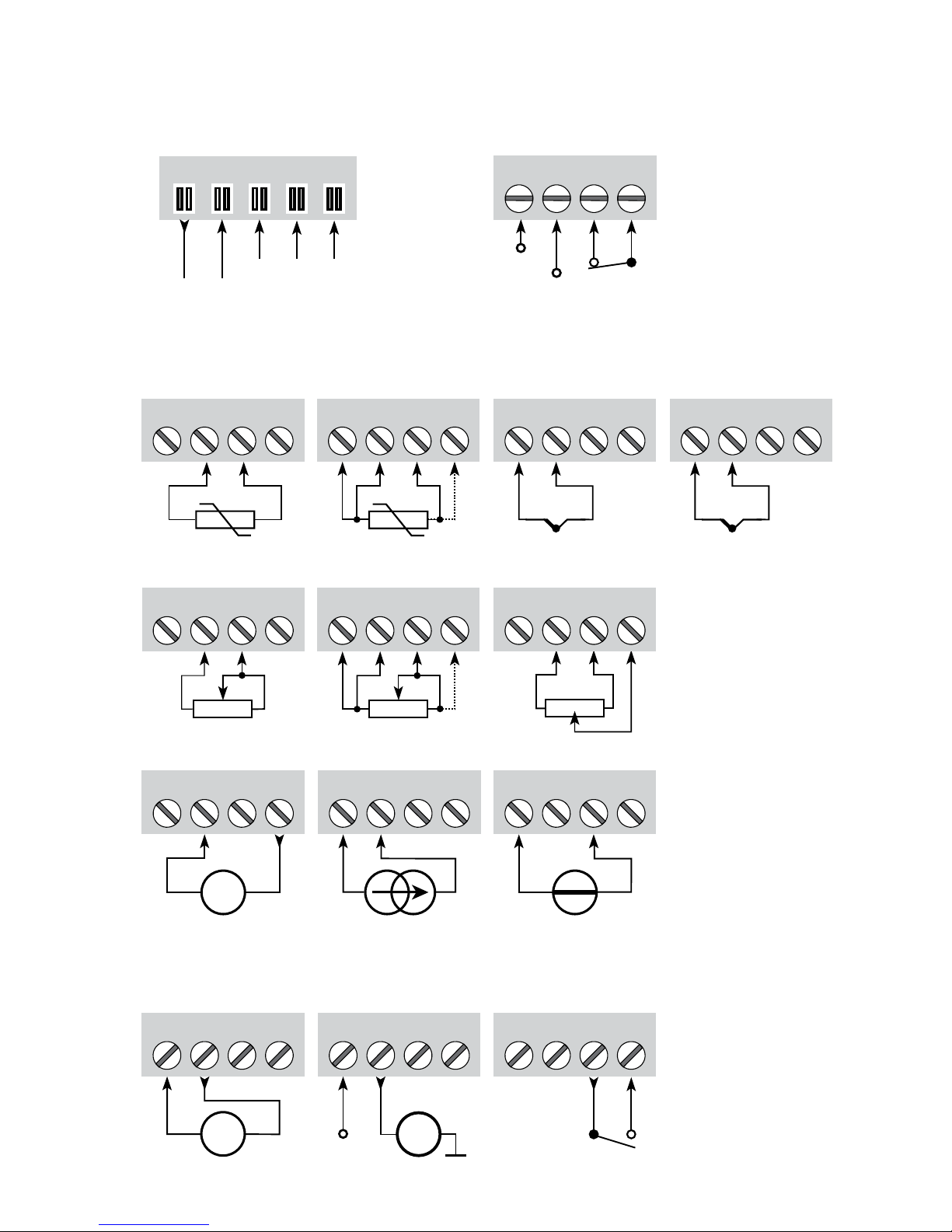
31 32 33 34
11 12 13 14
51 52 53 54
+
-
51 52 53 54
+
-
41 42 43 44 41 42 43 44
41 42 43 44 41 42 43 44
+
-
41 42 43 44
41 42 43 44
+
-
41 42
CJC
44
51 52 53 54
+
-
Tx
11 12 13 14
+
-
mA
mA
+
11 12 13 14
N.O.
+24 V
N.F.
91 92 93 94 95
NCNC
+24 V
1 3
2
9116 - Product Version 9116-001 81
CONNEXIONS
Entrées :
Sortie :
Alimentation et
relais d’état
Courant
(sortie active)
Relais
Pt100, 3- / 4-filsPt100, 2-fils
Résistance, 2-fils
Résistance,
3- / 4-fils
Potentiomètre
Courant TensionTransmetteur 2-fils
Masse
Transmetteur 2-fils
(sortie passive)
* Commander
separément :
Connecteur CSF
5910Ex
Masse
Connexions au rail
d’alimentation
NC = pas de connexion
Signal d’erreur
TC, capteur
CSF interne
*TC,
Connecteur CSF
Page 84
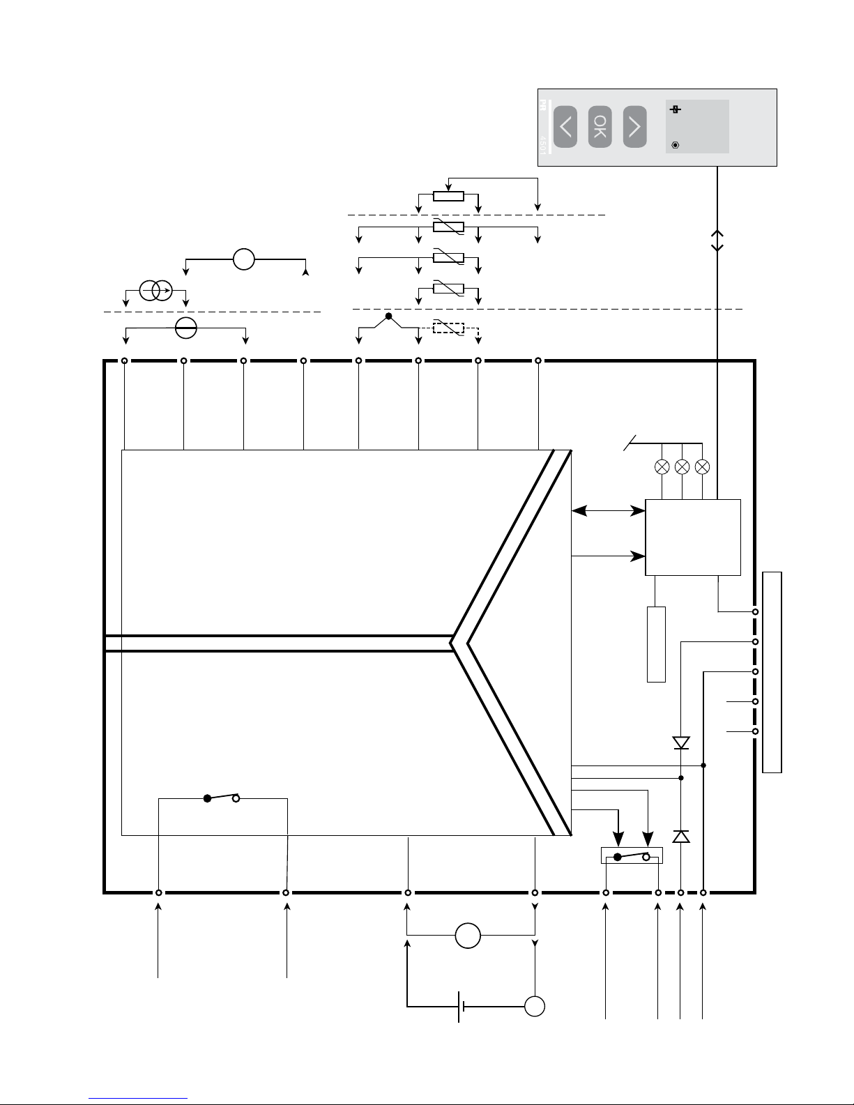
9116
51
31
14
32
34
33
12
11
13
54
53
52
44
43
42
41
NC*NC*
+24V
CPU
FLASH
I
o20 mA
I
800.0
1
+
-
+
-
Tx
4
3
2
*
+
-
I+
mA
mA
+
-
82 9116 - Product Version 9116-001
SCHEMA DE PRINCIPE
Etat de module,
verte
Etat de relais, jaune
Etat de voie, rouge
Relais d’état N.F.
Relais d’état N.F.
Masse
Alimentation +24 Vcc
Relais N.O.
Relais N.O.
Masse
Connexions au rail d’alimentation
Pt100, conn.
fils
Potentiomètre
TC
Ten-
sion
Courant
Entrée
Sortie
mA
Alimentation
Sortie
relais
* NC = pas de connexion
Page 85
9116 - Product Version 9116-001 83
Liste d’indications des LED et signaux d’erreur
Etat LED verte
Relais:
LED jaune
Erreur:
LED rouge
Relais
d’état, N.F.
Etat de signal
pour le rail
Pas d’alimentation OFF OFF OFF Désexcité Fermé
Défaut module OFF ON Désexcité Fermé
Module OK Clignotante Excité Ouvert
Signal OK Clignotante OFF Excité Ouvert
Relais de sortie exité Clignotante ON OFF Excité Ouvert
Relais de sortie exité par court circuit / rupture Clignotante ON Clignotante Désexcité Fermé (si activé)
Relais de sortie désexité par court circuit / rupture Clignotante OFF Clignotante Désexcité Fermé (si activé)
Relais de sortie désexité Clignotante OFF OFF Excité Ouvert
Indications d’erreur signal et câble sans la façade 4501
Page 86

84 9116 - Product Version 9116-001
PROGRAMMATION /
OPERATION DES TOUCHES DE FONCTION
Documentation pour le diagramme de programmation.
Généralités
Lors de la configuration du 9116 vous êtes guidés tout au long des paramètres
du menu ; ainsi vous pouvez choisir le réglage qui correspond à votre
application. Pour chaque menu il y a un texte d’aide qui défile en ligne 3 de
l’indicateur.
La configuration se fait à l’aide des 3 touches de fonction :
1 Incrémenter la valeur numérique ou choisir le paramètre suivant
2 Décrémenter la valeur numérique ou choisir le paramètre précédent
3 Valider les valeurs choisies et fin du menu
Une fois la configuration terminée, l’indicateur retournera sur l’état défaut 1.0.
En appuyant et maintenant la touche 3 l’indicateur retourne au menu précédent
ou sur l’état défaut (1.0) sans sauvegarde des modifications éventuelles
apportées à la configuration.
Si aucune touche n’est activée pendant 1 minute, l’indicateur retournera sur
l’état défaut sans sauvegarde des modifications éventuelles apportées à la
configuration.
Informations complémentaires
Protection par mot de passe : L’accès à la programmation peut être bloqué
par un mot de passe. Ce mot de passe est sauvegardé dans le module
afin d’assurer un haut niveau de protection contre les modifications non
autorisées. Le mot de passe usine 2008 permet l’accès à tous les menus
de configuration. Protection par mot de passe est obligatoire dans les
applications SIL.
Sélection des unités
Après sélection du type de signal d’entrée vous pouvez choisir l’unité de valeur
du process pour l’affichage en texte (voir tableau). En sélectionnant une entrée
température, l’unité de mesure sur l’afficheur est en Celsius ou Fahrenheit. Ce
choix se fait dans le point de menu après sélection d’entrée température.
Page 87

9116 - Product Version 9116-001 85
CSF (CJC)
Dans le menu CJC vous pouvez choisir entre connecteur CSF ou compensation
de soudure froide interne. Le connecteur CSF (PR 5910Ex) est à commander
séparemment.
Informations relatives à l’erreur de câble sur la façade 4501
Erreur de câble (voir limites dans tableau) est affiché par CA.BR (rupture câble)
ou CA.SH (court circuit câble). Signal hors limites (voir tableau des limites)
est affiché par IN.LO (limite basse) ou IN.HI (limite haute). L’affichage de
l’erreur se fait en format texte sur la ligne 1 avec le rétro-éclairage lumineux
clignotant. La ligne 4 de l’affichage indique l’état SIL (point statique =
verrouillage SIL, point clignotante = aucun verrouillage SIL) ainsi que l’état
du relais et de la communication (point avec cercle) qui indique l’état de
fonctionnement du 4501.
Indication du signal et erreur capteur sans la façade
L’état du module peut être lu sur la façade à l’aide des 3 voyants.
Voyant vert clignotant indique l’état normal de fonctionnement.
Si le voyant vert n’est pas illuminé, cela indique un défaut d’alimentation ou
une erreur dans le module.
Voyant rouge fixe indique une erreur fatale.
Voyant rouge clignotant indique une erreur capteur.
Fonctions du relais
5 différentes fonctions peuvent être sélectionnées :
Consigne : Fonctionnement en relais à seuils.
Fenêtre : Le relais a une fenêtre définie par le seuil bas et haut.
Des deux cotés de la fenêtre le relais a le même état.
Fonction erreur : Le relais est activé en cas d’erreur capteur.
Alimentation : Le relais est actif en présence de l’alimentation.
OFF : Le relais est désactivé.
Croissant / Décroissant : Le relais peut être actif en mode croissant ou
décroissant.
Délais : Fonctions Délai “ON” ou “OFF” peuvent être choisies pour le relais
entre 0...3600 s.
Hystérésis : L’hystérésis peut être configuré entre 0,1 et 25% de l’échelle ou
entre 1 et 25 % de la gamme d’affichage.
Page 88

86 9116 - Product Version 9116-001
Fenêtre : La fonction Fenêtre « Window » est choisie dans le menu en
définissant le point haut ou bas du seuil.
Voir le graphique déscriptif de la fonction fenêtre à la page 94.
Consigne : La fonction consigne « Setpoint » est choisie dans le menu en
indiquant les limites souhaitées. Le module alors fonctionne comme un
simple relais à seuils.
Voir le graphique déscriptif de la fonction consigne à la page 95.
Un relais actif signifie que le contact est fermé et défini en « Normalement
ouvert » et le contact est ouvert lorsque il est en « normalement fermé ».
Il est possible d’activer ou désactiver la fonction temporisation « délai » sur le
menu ON.DEL et OFF DEL.
Fonctions avancées
L’unité donne accès à un certain nombre de fonctions avancées qui sont
accessibles en répondant « YES » à « ADV.SET ».
Configuration de l’affichage : Il est possible de régler la luminosité et le
rétro-éclairage. Enregistrement d’un numéro de repère à 5 caractères
alphanumériques. La valeur d’entrée est toujours affichée en ligne 2.
Sélection de l’affichage en ligne 3 de l’indicateur - choix entre : sortie
analogique et numéro répère. En sélectionnant ”ALT” l’affichage alterne les
informations affichées.
Calibration du process en 2 points
: L’unité peut procéder à une calibration
en 2 points. Le point mini du signal d’entrée (pas nécessairement 0%)
est appliquée et la valeur actuelle est entrée sur l’unité 4501. Ensuite le
point maxi du signal (pas nécessairement 100%) est appliquée et la valeur
actuelle est entrée sur l’unité 4501. Si vous validez ces points, l’appareil va
fonctionner selon cet ajustement. Si plus tard vous souhaitez modifier ou
changer de type d’entrée l’unité reviendra à la calibration usine.
Fonction simulation : Si vous validez le point « EN.SIM » il est possible de
simuler un signal d’entrée à l’aide des flèches et ainsi contrôler le signal de
sortie haut et bas ou l’état du relais OFF et ON. Vous devez sortir du menu
en pressant 3 (pas de time-out). La simulation sera terminée, si le 4501 est
enlevé.
Page 89

9116 - Product Version 9116-001 87
Mot de passe : Ici vous pouvez choisir un mot de passe allant de 0000 à 9999
afin de protéger la programmation. L’unité est livrée sans mot de passe.
Mémoire : Dans le menu mémoire (memory) vous pouvez sauvegarder la
configuration du module dans le 4501, et puis transférer le 4501 sur un
autre module du même type et charger la configuration sauvegardée vers ce
module.
Langue : Dans le menu « LANG », vous pouvez sélectionner 7 différentes
langues pour le texte d’aide. Choix entre : Anglais, allemand, français, italien,
espagnol, suédois et danois.
Rail d’alimentation
: Dans le menu ”RAIL” vous pouvez choirsir si des erreurs
capteur doivent être transmis à l’unité de surveillance du module PR 9410
Contrôleur d’alimentation.
Safety Integrity Level (SIL): Voir le ”Safety Manual” (en Anglais)
pour information supplémentaire.
Page 90
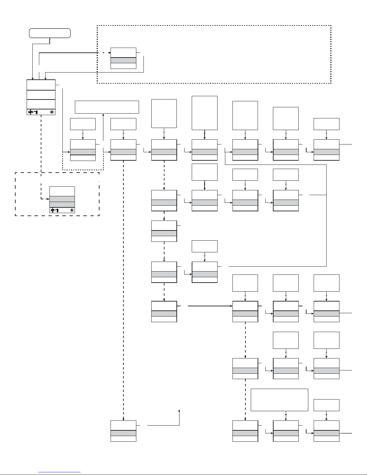
1
0000
PASSW.
Txt 1
3
3
0000
9999
1 2
NO
ADV.SET
Txt 2
NO
YES
1 2
3
VOLT
IN TYPE
Txt 3
VOLT
LIN.R
POTM
CURR
TEMP
1 2
3
50.0
SETP.
Txt 57
3
1 2
2-10
V.RANGE
Txt 4
2-10
0-10
1-5
0-5
0.2-1
0-1
1 2
3
TEMP
IN TYPE
Txt 3
3
Pt
SENSOR
Txt 10
Pt
NI
TC
1 2
3
YES
ADV.SET
3
Ni
SENSOR
Txt 10
3
TC
SENSOR
3
100
Pt TYPE
Txt 16
1000
-
10
1 2
3
3W
CONNEC.
Txt 6
4W
3W
2W
1 2
100
Ni TYPE
Txt 17
1000
-
50
1 2
TC.K
TC.TYPE
TC.B TC.E TC.J TC.K
TC.L TC.N TC.R TC.S
TC.T TC.U TC.W3
TC.W5 TC.Lr
1 2
0.0
DISP.LO
Txt 13
999.9
-199.9
1 2
111.1
DEC.P
Txt 12
1111
111.1
11.11
1.111
1 2
3
UNIT
%
Txt 11
@C
mA
rpm
(70 units)
1 2
3
CURR
IN TYPE
Txt 3
3
4-20
I.RANGE
Txt 5
0-20
4-20
1 2
3
LIN.R
IN TYPE
Txt 3
3
3W
CONNEC.
Txt 6
4W
3W
2W
1 2
3
POTM
IN TYPE
Txt 3
3
0
R 0%
Txt 7
0000
9999
1 2
3
0
R 100%
Txt 8
0000
9999
1 2
3
1.0
1.2
1.1
3
3W
CONNEC.
Txt 6
4W
3W
2W
1 2
3
3W
CONNEC.
Txt 6
4W
3W
2W
1 2
3
CJC
INT
CONN
1 231 2
SE.BR
o3.50mA
INT
Txt 2 Txt 10 Txt 18 Txt 31
Power up
Io12.00mA
I
I
30.00
88 9116 - Product Version 9116-001
Continué à la page
Diagramme de
programmation
ADV.SET
Réglage rapide des consignes et
test du relais
1 Incrémentation de la consigne
2 Décrémentation de la consigne
3 Sauvegarde des valeurs et sorti du menu
1 et 2 simultanément = le relais change d’état
Indication d’erreur, exemple
Si le verrouillage SIL est activé
directement en [EN.SIL]
Texte rouge signifie des
paramètres de sécurité
dans une configuration SIL.
Voir le ”Safety Manual” (en
Anglais) pour information
supplémentaire.
Page 91
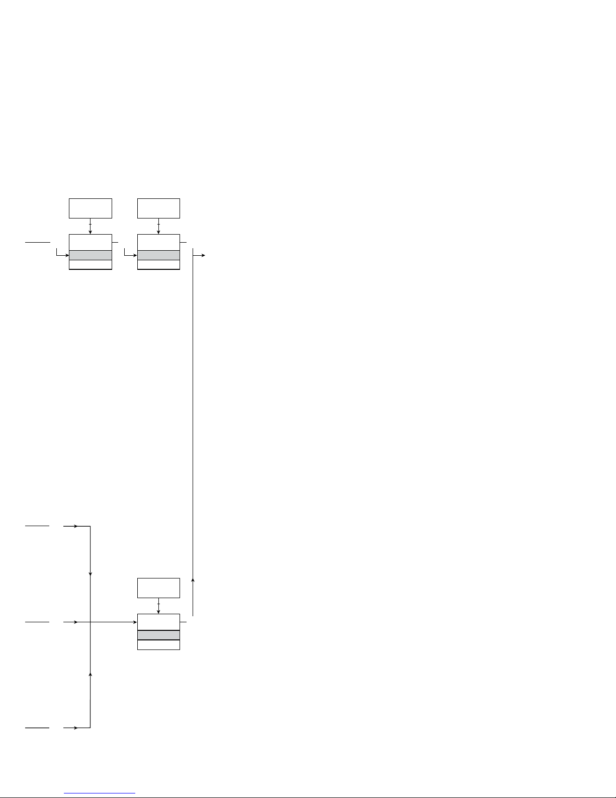
@C
@F
K
%
m
cm
mm
um
ft
in
mils
yd
m3
l
s
min
m/s
mm/s
m/min
m/h
in/s
ips
ft/s
in/min
ft/min
in/h
ft/h
m/s2
rpm
Hz
t
kg
g
N
Pa
MPa
kPa
hPa
bar
mbar
kj
Wh
MWh
kWh
W
GW
MW
kW
hp
A
kA
mA
uA
V
kV
mV
ohm
S
uS
m3/min
m3/h
l/s
l/min
l/h
gal/min
gal/h
t/h
mol
pH
[blank]
Txt 9
3
100.0
DISP.HI
Txt 14
999.9
-199.9
1 2
3
DISP
REL.UNI
Txt 15
DISP
PERC
1 2
@C
UNIT
@C
@F
1 2
3
3
3
3
3
9116 - Product Version 9116-001 89
1.0 = Etat défaut. Ligne 1
affiche l’état d’entrée,
ligne 2 affiche l’entrée et
numéro répère, ligne 3
affiche la sortie et les
unités et ligne 4 affiche
l’etat de relais et de
communication ainsi que
l’état SIL (ouvert / verrouillé).
Point statique = verrouillage
SIL, point clignotante =
aucun verrouillage SIL.
1.1 = Seulement si l’indicateur
est protégé par un mot de
passe.
1.2 = Seulement si le Réglage
Rapide est activé et le
relais a la fonction consigne.
1.3 = Seulement si le type
d’entrée supporte le
contrôle d’erreur de câble
Ne vaut pas pour les
signaux d’entrée :
0...20 mA et tension.
1.4 = Seulement si le signal
d’entrée est température.
1.5 = Seulement si la configu ration n’est pas protégé
par un mot de passe
Continué à la page suivante
DIAGRAMME DE PROGRAMMATION
Si aucune touche n’est actionnée pendant 1 minute, l’indicateur retournera
sur l’état défaut sans sauvegarde des modifications éventuelles apportées à la
configuration.
1Incrémenter la valeur / choisir paramètre suivant
2 Décrémenter la valeur / choisir paramètre précédent
3Valider les valeurs choisies et fin du menu
Maintien 3 Retour au menu précédent / retour au menu 1.0 sans sauvegarde
Choix de l’
UNITES :
Page 92
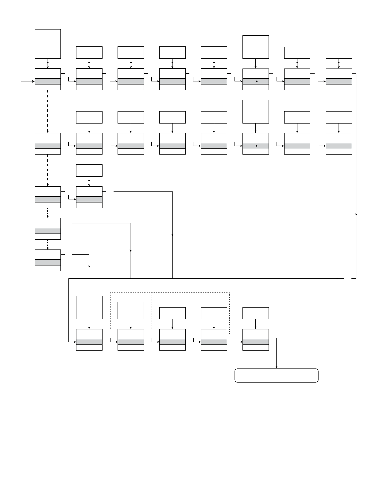
0
ON.DEL
Txt 25
3600
0000
1 2
NONE
ERR.ACT
Txt 24
HOLD
CLOS
OPEN
NONE
1 2
3
0
OFF.DEL
Txt 26
3600
0000
1 2
3
0
ON.DEL
Txt 25
3600
0000
1 2
NONE
ERR.ACT
Txt 24
HOLD
CLOS
OPEN
NONE
1 2
3
0
OFF.DEL
Txt 26
3600
0000
1 2
3
3
1.3
1.3
4-20
O.RANGE
Txt 37
20-4
20-0
4-20
0-20
1 2
3
23mA
OUT.ERR
Txt 38
23mA
0/3.5mA
NONE
1 2
3
0.0
OUT.LO
Txt 41
849
-200
1 2
3
150.0
OUT.HI
Txt 42
850.0
-199.0
1 2
1.3
1.4 1.4
3
0.0
RESP.
Txt 39
0.0
60
1 2
N.O.
CONTAC
Txt 20
3
N.O.
N.C.
1 2
50.0
SETP.
Txt 21
850
-200
1 2
3
INCR
ACT.DIR
Txt 22
INCR
DECR
1 2
3
1.0
HYST.
Txt 23
262.5
0.1
1 2
SETP
REL.FUN
Txt 19
SETP
WIND
ERR
POW
OFF
1 2
3
O.I.W
CONTAC
Txt 27
3
O.I.W
C.I.W
1 2
50.0
SETP.LO
Txt 28
849.9
-200
1 2
3
60.0
SETP.HI
Txt 28
850.0
-199.9
1 2
3
1.0
HYST.
Txt 30
262.5
0.1
1 2
WIND
REL.FUN
Txt 19
3
OPEN
ERR.ACT
Txt 34
3
CLOS
OPEN
1 2
ERR
REL.FUN
Txt 19
3
POW
REL.FUN
Txt 19
OFF
REL.FUN
Txt 19
3
3
1.3
3
3
3
90 9116 - Product Version 9116-001
Retour au menu 1.0
Page 93
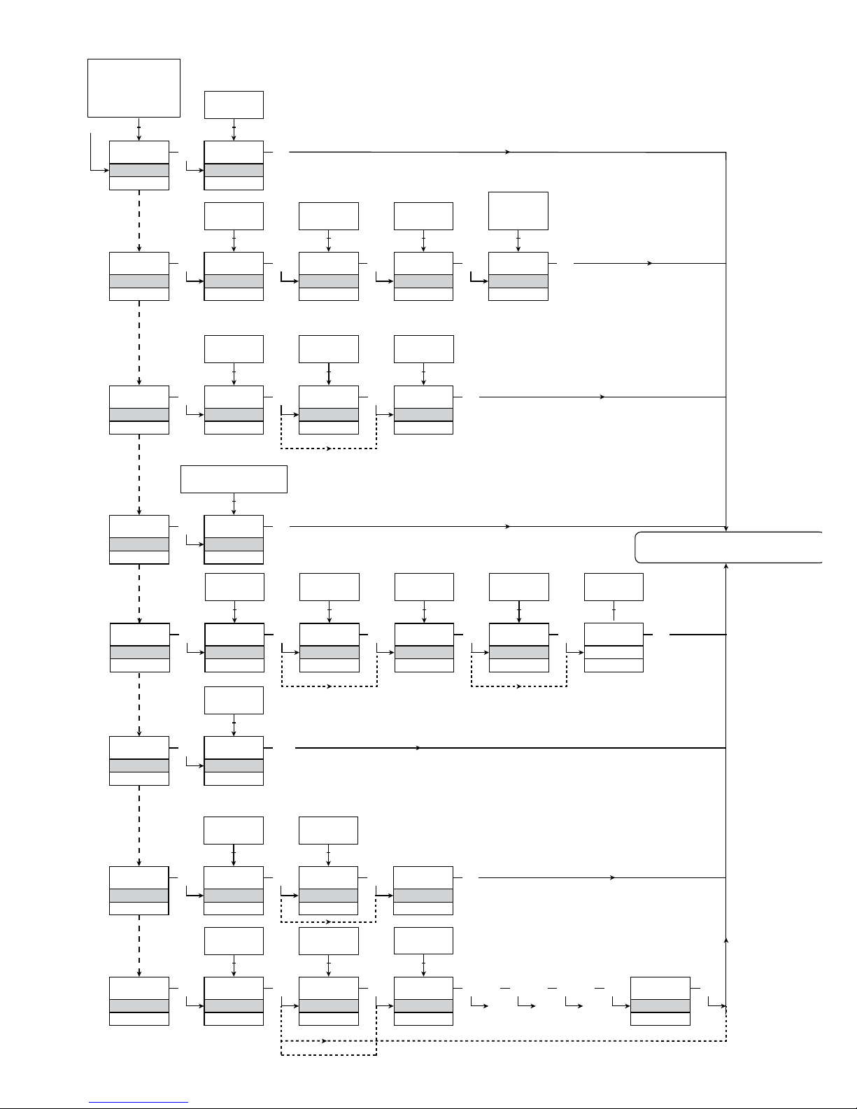
SAVE
MEMORY
Txt 44
3
SAVE
LOAD
1 2
MEM
SETUP
Txt 43
MEM, DISP,
PASS, LANG,
CAL, RAIL,
SIM, SIL
1 2
3
DISP
SETUP
Txt 43
3
3
CONTRA
Txt 45
3
9
0
1 2
9
LIGHT
Txt 46
3
9
0
1 2
TAG.1
TAGNO
Txt 47
3
9
A
1 2
A.OUT
DISP
Txt 48
3
TAG
ALT
A.OUT
1 2
CAL
SETUP
Txt 43
3
YES
CAL.LO
Txt 49
3
YES
NO
1 2
2.0
@C
Txt 61
3
850.0
-200.0
1 2
NO
YES
CAL.HI
Txt 50
3
YES
NO
1 2
147.8
@C
Txt 62
3
850.0
-200.0
1 2
NO
3
USE.CAL
Txt 60
YES
NO
1 2
SIM
SETUP
Txt 43
3
YES
EN.SIM
Txt 51
3
YES
NO
1 2
23.0
%
Txt 52
3
850.0
-200.0
1 2
NO
REL.SIM
Txt 53
3
2.0
RAIL
SETUP
Txt 43
3
YES
RAIL.ER
Txt 63
3
YES
NO
1 2
SIL
SETUP
Txt 43
3
YES
EN.SIL
Txt 64
YES
NO
1 2
NO
3
2008
NEW.PAS
Txt 55
0000
9999
1 2
3
LOCK
CONFIG
Txt 66
SIL.OK
. . . . . . . . . . . . . .
3 3 3 3 3
OPEN
LOCK
1 2
LANG
SETUP
Txt 43
3
UK
LANGUA
Txt 59
3
DE, DK, ES, FR,
IT, SE, UK
1 2
PASS
SETUP
Txt 43
3 3
YES
EN.PASS
Txt 54
3
YES
NO
1 2
NO
0000
NEW.PAS
Txt 55
3
9999
0000
1 2
YES
EN.FAST
Txt 56
YES
NO
1 2
3
YES
1.4
9116 - Product Version 9116-001 91
DIAGRAMME DE PROGRAMMATION,
REGLAGE AVANCE (ADV.SET)
Retour au menu 1.0
Vérification de la
configuration SIL
2.0 Dans le sous-menu simulation (SIM) il faut
actionner 3 pour retourner sur l’état defaut 1.0
Page 94

92 9116 - Product Version 9116-001
MENU DEROULANT EN LIGNE 3 DE L’INDICATEUR
[01]
[02]
[03]
[04]
[05]
[06]
[07]
[08]
[09]
[10]
[11]
[12]
[13]
[14]
[15]
[16]
[17]
[18]
[19]
[20]
[21]
[22]
[23]
[24]
[25]
[26]
[27]
[28]
[29]
[30]
[31]
[34]
[37]
[38]
[39]
[41]
[42]
[43]
[44]
[45]
[46]
[47]
[48]
[49]
[50]
[51]
[52]
[53]
[54]
[55]
[56]
Entrer mot de passe correct
Aller dans le menu de configuration avancée ?
Sélectionner entrée température
Sélectionner entrée potentiomètre
Sélectionner entrée résistance linéaire
Sélectionner entrée courant
Sélectionner entrée tension
Sélectionner gamme d’entrée 0.0-1 V
Sélectionner gamme d’entrée 0.2-1 V
Sélectionner gamme d’entrée 0-5 V
Sélectionner gamme d’entrée 1-5 V
Sélectionner gamme d’entrée 0-10 V
Sélectionner gamme d’entrée 2-10 V
Sélectionner gamme d’entrée 0-20 mA
Sélectionner gamme d’entrée 4-20 mA
Sélectionner connexion capteur 2-fils
Sélectionner connexion capteur 3-fils
Sélectionner connexion capteur 4-fils
Régler valeur de résistance basse
Régler valeur de résistance haute
Sélectionner Celsius comme unité de température
Sélectionner Fahrenheit comme unité de
température
Sélectionner type de capteur TC
Sélectionner type de capteur Ni
Sélectionner type de capteur Pt
Sélectionner unités d’affichage
Sélectionner position du point décimale
Régler gamme d’affichage basse
Régler gamme d’affichage haute
Régler consigne relais en pourcentages de la
gamme d’entrée
Régler Consigne relais en unités d’affichage
Sélectionner Pt10 comme type de capteur
Sélectionner Pt20 comme type de capteur
Sélectionner Pt50 comme type de capteur
Sélectionner Pt100 comme type de capteur
Sélectionner Pt200 comme type de capteur
Sélectionner Pt250 comme type de capteur
Sélectionner Pt300 comme type de capteur
Sélectionner Pt400 comme type de capteur
Sélectionner Pt500 comme type de capteur
Sélectionner Pt1000 comme type de capteur
Sélectionner Ni50 comme type de capteur
Sélectionner Ni100 comme type de capteur
Sélectionner Ni120 comme type de capteur
Sélectionner Ni1000 comme type de capteur
Sélectionner TC-B comme type de capteur
Sélectionner TC-E comme type de capteur
Sélectionner TC-J comme type de capteur
Sélectionner TC-K comme type de capteur
Sélectionner TC-L comme type de capteur
Sélectionner TC-N comme type de capteur
Sélectionner TC-R comme type de capteur
Sélectionner TC-S comme type de capteur
Sélectionner TC-T comme type de capteur
Sélectionner TC-U comme type de capteur
Sélectionner TC-W3 comme type de capteur
Sélectionner TC-W5 comme type de capteur
Sélectionner TC-Lr comme type de capteur
Sélectionner Fonction OFF - le relais est en
permanence OFF
Sélectionner Fonction POWER - le relais indique état
d’alimentation OK
Sélectionner Fonction ERREUR - le relais indique
uniquement erreur capteur
Sélectionner Fonction FENETRE - le relais est
contrôlé par 2 consignes
Sélectionner Fonction CONSIGNE - le relais est
contrôlé par 1 consigne
Sélectionner contact Normalement Fermé
Sélectionner contact Normalement Ouvert
Régler consigne du relais
Sélectionner activation du relais pour un signal
descendant
Sélectionner activation du relais pour un signal montant
Régler hystérésis du relais
Sélectionner aucune action d’erreur - état non-défini
en cas d’erreur
Sélectionner ouvrir contact du relais en cas d’erreur
Sélectionner fermer contact du relais en cas d’erreur
Sélectionner Maintenir état du relais en cas d’erreur
Régler délai ON du relais en secondes
Régler délai OFF du relais en secondes
Sélectionner contact du relais est fermé dans la fenêtre
Sélectionner contact du relais est ouvert dans la fenêtre
Régler consigne basse de la fenêtre relais
Régler consigne haute de la fenêtre relais
Régler hystérésis de la fenêtre relais
Sélectionner capteur de température interne
Sélectionner bornier CSF (accessoire)
Sélectionner ouvrir contact du relais en cas d’erreur
Sélectionner fermer contact du relais en cas d’erreur
Sélectionner gamme de sortie 0-20 mA
Sélectionner gamme de sortie 4-20 mA
Sélectionner gamme de sortie 20-0 mA
Sélectionner gamme de sortie 20-4 mA
Sélectionner aucune action d’erreur - sortie pas définie
en cas d’erreur
Sélectionner bas d’échelle en cas d’erreur
Sélectionner NAMUR NE43 bas d’échelle en cas
d’erreur
Sélectionner NAMUR NE43 haut d’échelle en cas
d’erreur
Régler Temps de réponse de la sortie analogique en
secondes
Régler température de la sortie analogique basse
Régler température de la sortie analogique haute
Aller dans la configuration SIL
Aller dans le mode simulation
Aller dans la configuration du rail d’alimentation
Exécuter calibration de process
Aller dans la configuration langue
Aller dans la configuration du mot de passe
Aller dans la configuration d’affichage
Exécuter opérations de mémoire
Charger la configuration sauvegardée au module
Sauvegarder la configuration dans la 4501
Ajuster le contraste LCD
Ajuster le rétro-éclairage LCD
Entrer numéro repère de 5 caractères
Valeur de la sortie analogique affichée en ligne 3
Numéro repère affiché en ligne 3
Alterner les informations affichées
Calibrer l’entrée basse à la valeur de process ?
Calibrer l’entrée haute à la valeur de process ?
Permettre simulation de l’entrée ?
Régler la valeur de simulation en entrée
Simulation relais - utiliser 1 pour alterner l’état du relais
Permettre protection par mot de passe ?
Entrer Nouveau mot de passe
Permettre la fonctionalité Réglage rapide ?
Page 95

9116 - Product Version 9116-001 93
[57]
[58]
[59]
[60]
[61]
[62]
[63]
[64]
[65]
[66]
[80]
[81]
[82]
[83]
[84]
[85]
[86]
[87]
[88]
[89]
[90]
[91]
[92]
[93]
Consigne relais - appuyer sur 3 pour sauvegarder
Consigne relais - Lecture
Sélectionner langue
Utiliser valeurs de calibration process ?
Régler valeur de la position basse de la calibration
Régler valeur de la position haute de la calibration
Activer signal d’état du rail d’alimentation
Permettre verrouillage de la configuration SIL ?
0-20 mA n’est pas une gamme de sortie valable en
opération SIL
... Est-ce que la voie utilise des données de
calibration compensées au process ?
Etat de la configuration SIL ( Ouverte / Verrouillée)
Court circuit du capteur
Rupture du câble capteur
Affichage en dessous du mini.
Affichage en dessus du maxi.
Entrée dépasse l’échelle basse
Entrée dépasse l’échelle haute
Erreur d’entrée - contrôler les connexions et
redémarrer le module
Erreur de sortie - contrôler connexions et
redémarrer le module
Erreur dans la mémoire FLASH - contrôler la
configuration
Configuration ou version invalide
Erreur matériel
Erreur du capteur CSF - contrôler la température
du module
Erreur CSF - contrôler le bornier CSF
Pas de communication
Page 96
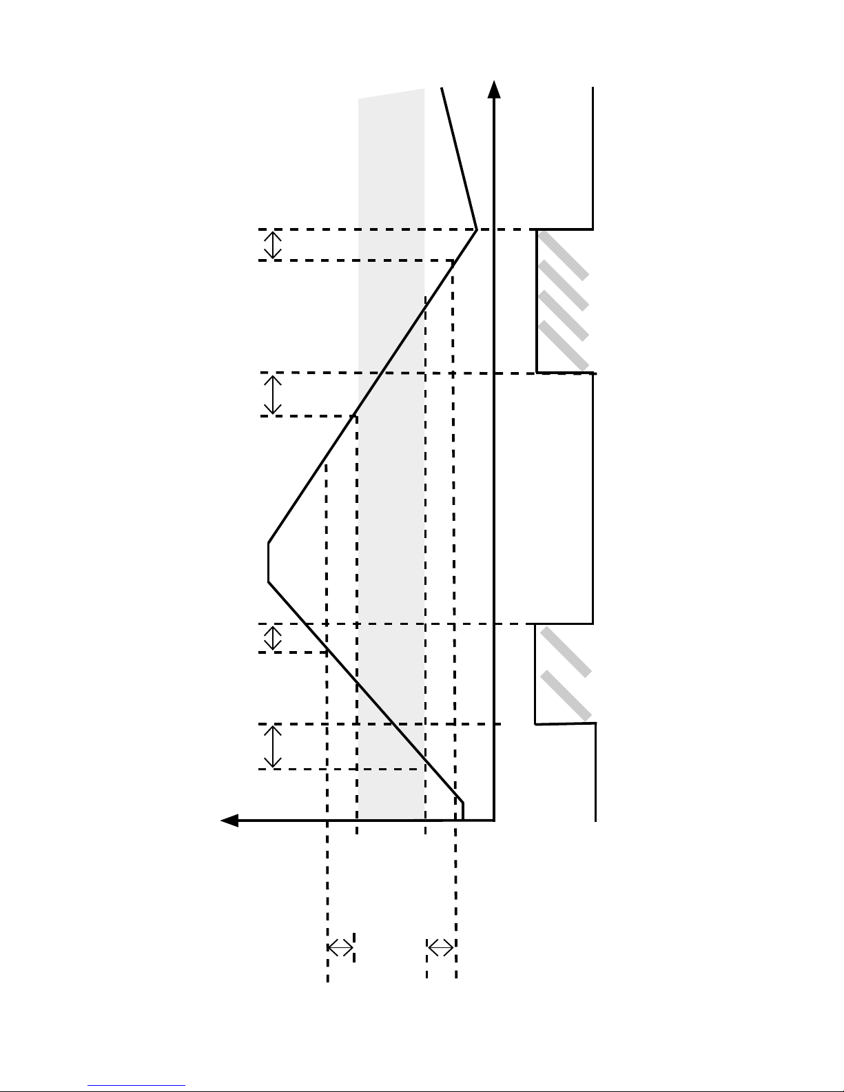
94 9116 - Product Version 9116-001
Graphique descriptif de la fonction fenêtre
Hystérésis
Consigne haute
Délai ON Délai OFF
Relais ON Relais ON
Fermé
Ouvert
Contact (N.O.)
Temps
Fenêtre
Délai ON Délai OFF
Hystérésis
Consigne basse
Page 97
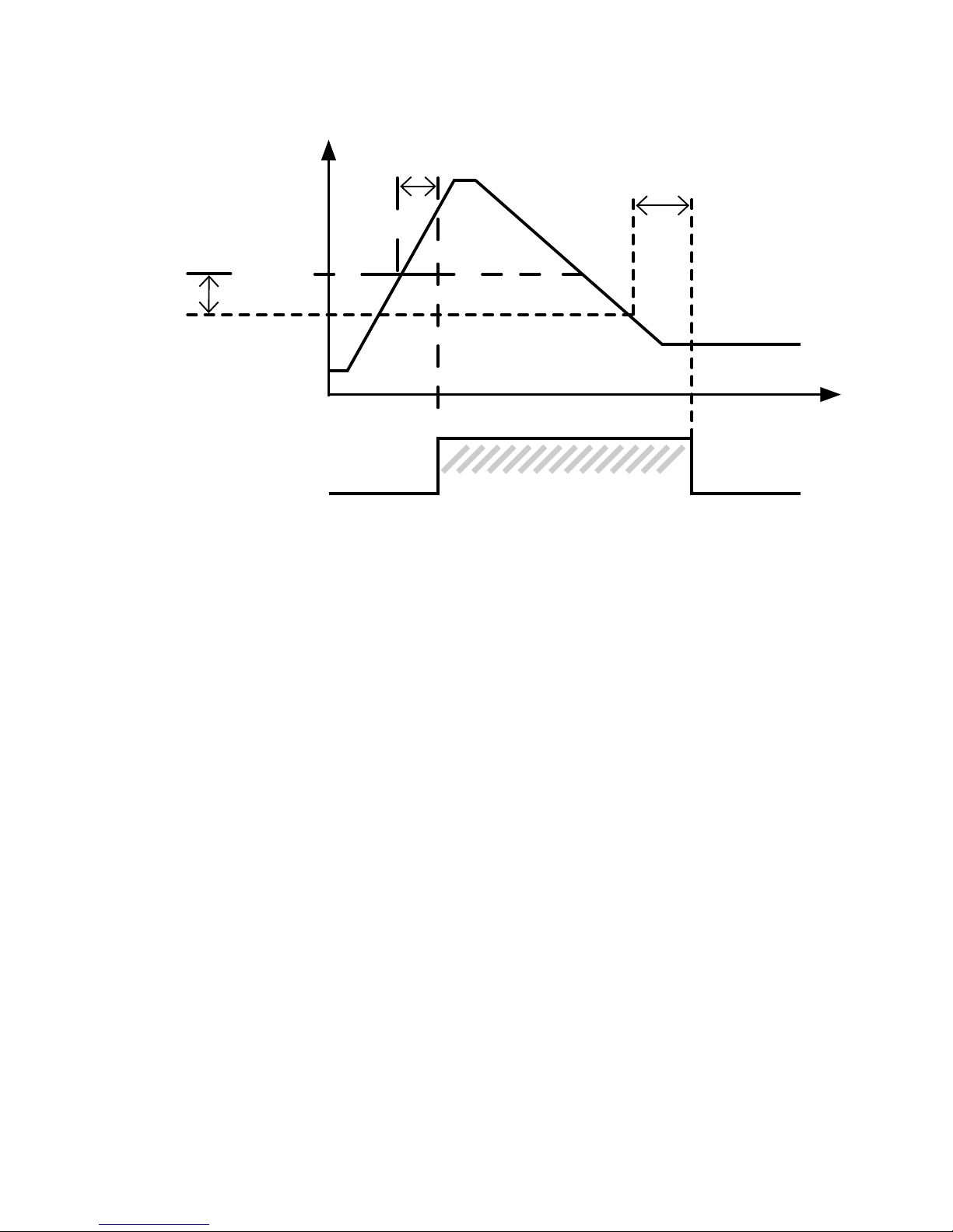
9116 - Product Version 9116-001 95
Graphique descriptif de la fonction consigne
Relais On
Délai OFF
Délai ON
Signal
d’entrée
Hystérésis
Consigne
(croissante)
Temps
Fermé
Ouvert
Contact
(N.O.)
Page 98

96 9116 - Product Version 9116-001
Page 99

9116 - Product Version 9116-001 97
UNIVERSALMESSUMFORMER
9116
INHALTSVERZEICHNIS
Warnung ......................................................................................... 98
Zeichenerklärungen ........................................................................ 98
Sicherheitsregeln ............................................................................ 98
Zerlegung des Systems 9000 ........................................................ 100
EG-Konformitätserklärung .............................................................. 101
Erweiterte Merkmale ...................................................................... 102
Verwendung .................................................................................... 102
Technische Merkmale ..................................................................... 102
Anwendungen ................................................................................ 103
PR 4501 Display / Programmierfront ............................................. 104
Bestellangaben ............................................................................... 105
Elektrische Daten ........................................................................... 105
Konfiguration der Sensorfehlerüberprüfung ................................... 109
Visualisierung im 4501:
Eingangssignal außerhalb des Bereichs .................................... 110
Fühlerfehlererkennung ............................................................... 110
Fehleranzeige ............................................................................. 111
Anschlüsse ..................................................................................... 113
Blockdiagramm .............................................................................. 114
Signalfehler- und Kabelfehler Erkennung ohne Frontdisplay ......... 115
Konfiguration / Bedienung der Funktionstasten ............................ 116
Flussdiagramm, erweiterte Einstellungen (ADV.SET) ..................... 123
Scrollender Hilfstext im Display Zeile 3 ......................................... 124
Grafische Abbildung der Relaisfunktion „Fenster“ ........................ 126
Grafische Abbildung der Relaisfunktion „Schaltpunkt“ ................. 127
Appendix ........................................................................................ 128
IECEx Installation Drawing......................................................... 129
ATEX Installation Drawings, UK, FR, DE, DK ............................ 133
FM Installation Drawing ............................................................. 149
Safety manual ............................................................................ 153
Page 100
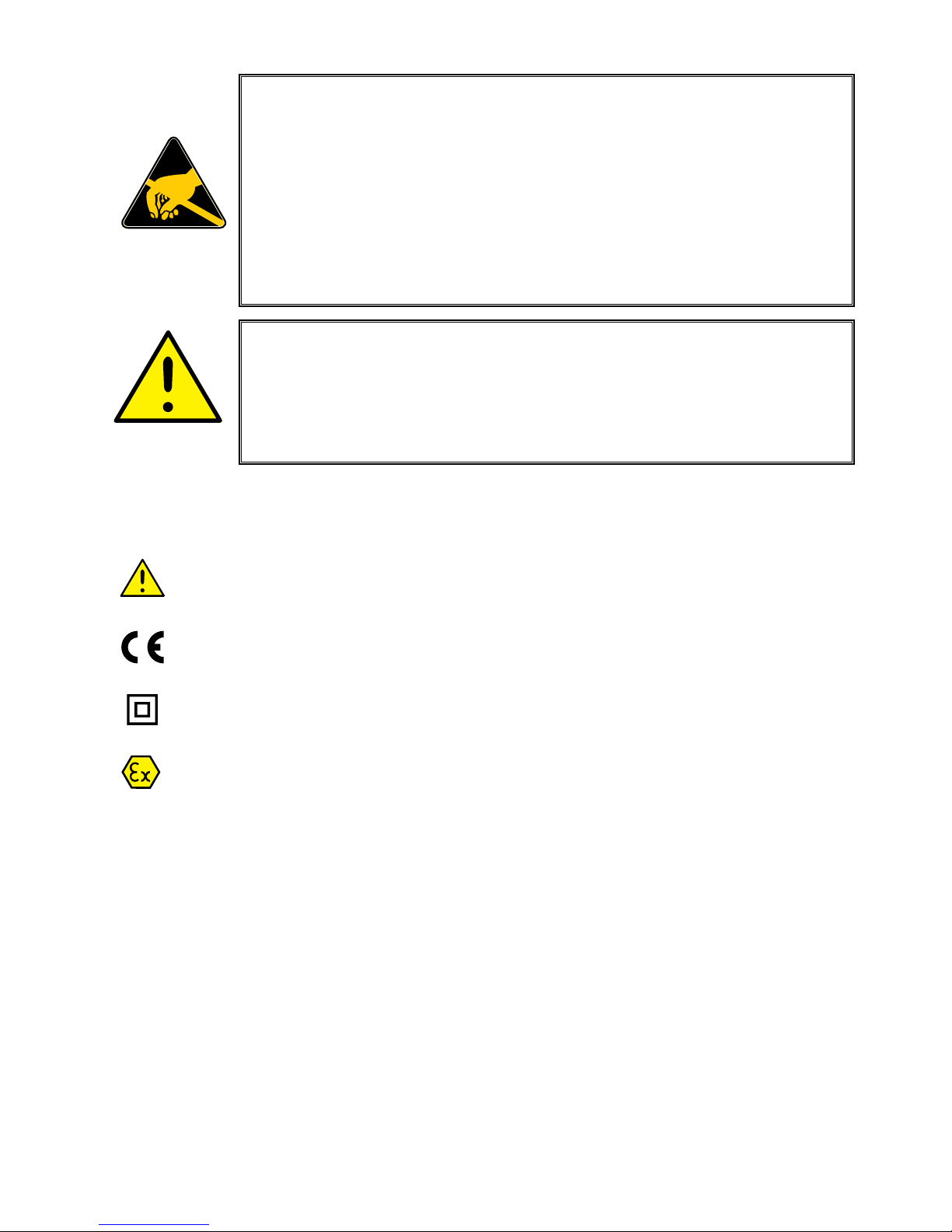
98 9116 - Product Version 9116-001
ZEICHENERKLÄRUNGEN
Dreieck mit Ausrufungszeichen: Das Handbuch ist sorgfältig
durchzulesen vor Montage und Inbetriebnahme des Gerätes, um
schweren Verletzungen oder mechanischer Zerstörung zu vermeiden.
Die CE-Marke ist das sichtbare Zeichen dafür, dass das Gerät die Vorschriften erfüllt.
Doppelte Isolierung ist das Symbol dafür, dass das Gerät besondere
Anforderungen an die Isolierung erfüllt.
Ex-Geräte sind entsprechend der ATEX Direktive für die Verwendung in
Ver bindung mit Installationen in explosionsgefährdeter Umgebung zugelassen. Siehe Installationszeichnung im Appendix.
SICHERHEITSREGELN
DEFINITIONEN
Gefährliche Spannungen sind definitionsgemäß die Bereiche: 75...1500 Volt
Gleichspannung und 50...1000 Volt Wechselspannung.
Techniker sind qualifizierte Personen, die dazu ausgebildet oder angelernt sind,
eine Installation, Bedienung oder evtl. Fehlersuche auszuführen, die sowohl
technisch als auch sicherheitsmäßig vertretbar ist.
Bedienungspersonal sind Personen, die im Normalbetrieb mit dem Produkt die
Drucktasten oder Potentiometer des Produktes einstellen bzw. bedienen und
die mit dem Inhalt dieses Handbuches vertraut gemacht wurden.
WARNUNG
Die folgende Maßnahmen sollten nur in spannungslosem
Zustand des Gerätes und unter ESD-sicheren Verhältnisse
durchgeführt werden:
Installation, Montage und Demontage von Leitungen.
Fehlersuche im Gerät.
Reparaturen des Gerätes und Austausch von Sicherungen
dürfen nur von PR electronics A/S vorgenommen werden.
WARNUNG
Die Frontplatte des Gerätes darf nicht geöffnet werden, weil
hier durch die Kontakte zur Kontaktierung des Frontdisplays
4501 beschädigt werden können. Das Gerät enthält keine internen DIP-Schalter oder Programmierbrücken.
 Loading...