

Page 1
PERFORMANCE
MADE
SMARTER
CCOE
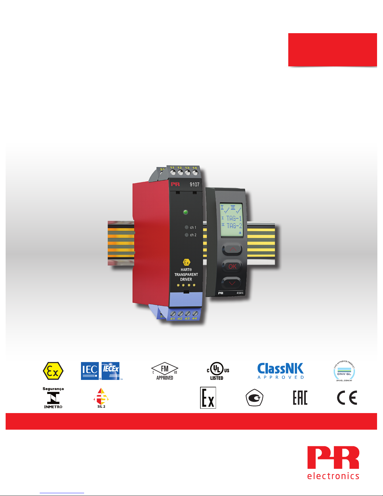
Product manual
9107B
HART transparent driver
TEMPERATURE | I.S. INTERFACES | COMMUNICATION INTERFACES | MULTIFUNCTIONAL | ISOLATION | DISPLAY
No. 9107V104-UK
Product version: 9107-002
Page 2
6 Product Pillars
to meet your every need
With our innovative, patented technologies, we make signal conditioning smarter and simpler. Our portfolio is composed of six
product areas, where we offer a wide range of analog and digital devices covering over a thousand applications in industrial
and factory automation. All our products comply with or surpass the highest industry standards, ensuring reliability in even
the harshest of environments and have a 5-year warranty for greater peace of mind.
Individually outstanding, unrivalled in combination
Our range of temperature transmitters and sensors provides the highest level of signal integrity from the
measurement point to your control system. You can convert industrial process temperature signals to analog, bus or
digital communications using a highly reliable point-to-point solution with a fast response time, automatic selfcalibration, sensor error detection, low drift, and top EMC performance in any environment.
Our unique range of single devices covering multiple applications is easily deployable as your site standard. Having
one variant that applies to a broad range of applications can reduce your installation time and training, and greatly
simplify spare parts management at your facilities. Our devices are designed for long-term signal accuracy, low
power consumption, immunity to electrical noise and simple programming.
We provide inexpensive, easy-to-use, future-ready communication interfaces that can access your PR installed base
of products. All the interfaces are detachable, have a built-in display for readout of process values and diagnostics,
and can be configured via push-buttons. Product specific functionality includes communication via Modbus and
Bluetooth and remote access using our PR Process Supervisor (PPS) application, available for iOS and Android.
Our display range is characterized by its flexibility and stability. The devices meet nearly every demand for display
readout of process signals, and have universal input and power supply capabilities. They provide a real-time
measurement of your process value no matter the industry, and are engineered to provide a user-friendly and
reliable relay of information, even in demanding environments.
We deliver the safest signals by validating our products against the toughest safety standards. Through our
commitment to innovation, we have made pioneering achievements in developing I.S. interfaces with SIL 2 Full
Assessment that are both efficient and cost-effective. Our comprehensive range of analog and digital intrinsically
safe isolation barriers offers multifunctional inputs and outputs, making PR an easy-to-implement site standard.
Our backplanes further simplify large installations and provide seamless integration to standard DCS systems.
Our compact, fast, high-quality 6 mm isolators are based on microprocessor technology to provide exceptional
performance and EMC-immunity for dedicated applications at a very low total cost of ownership. They can be
stacked both vertically and horizontally with no air gap separation between units required.
Page 3

9107 - Product version 9107-002 3
HART transparent driver
9107B
Table of contents
Warning ................................................................................................ 4
Symbol identification .................................................................................... 4
Safety instructions ...................................................................................... 4
How to demount system 9000 ........................................................................... 5
Application ............................................................................................. 6
Advanced features ...................................................................................... 6
Technical characteristics ................................................................................. 6
Applications ............................................................................................ 7
PR 4511/4501 display / programming front............................................................... 8
Mounting / demounting the PR 4511/4501 . . . . . . . . . . . . . . . . . . . . . . . . . . . . . . . . . . . . . . . . . . . . . . . . . . . . . . . . . . . . . . . 8
Order ................................................................................................... 9
Accessories ............................................................................................. 9
Technical data .......................................................................................... 9
Visualisation in the 4511/4501 of hardware/software error................................................ 12
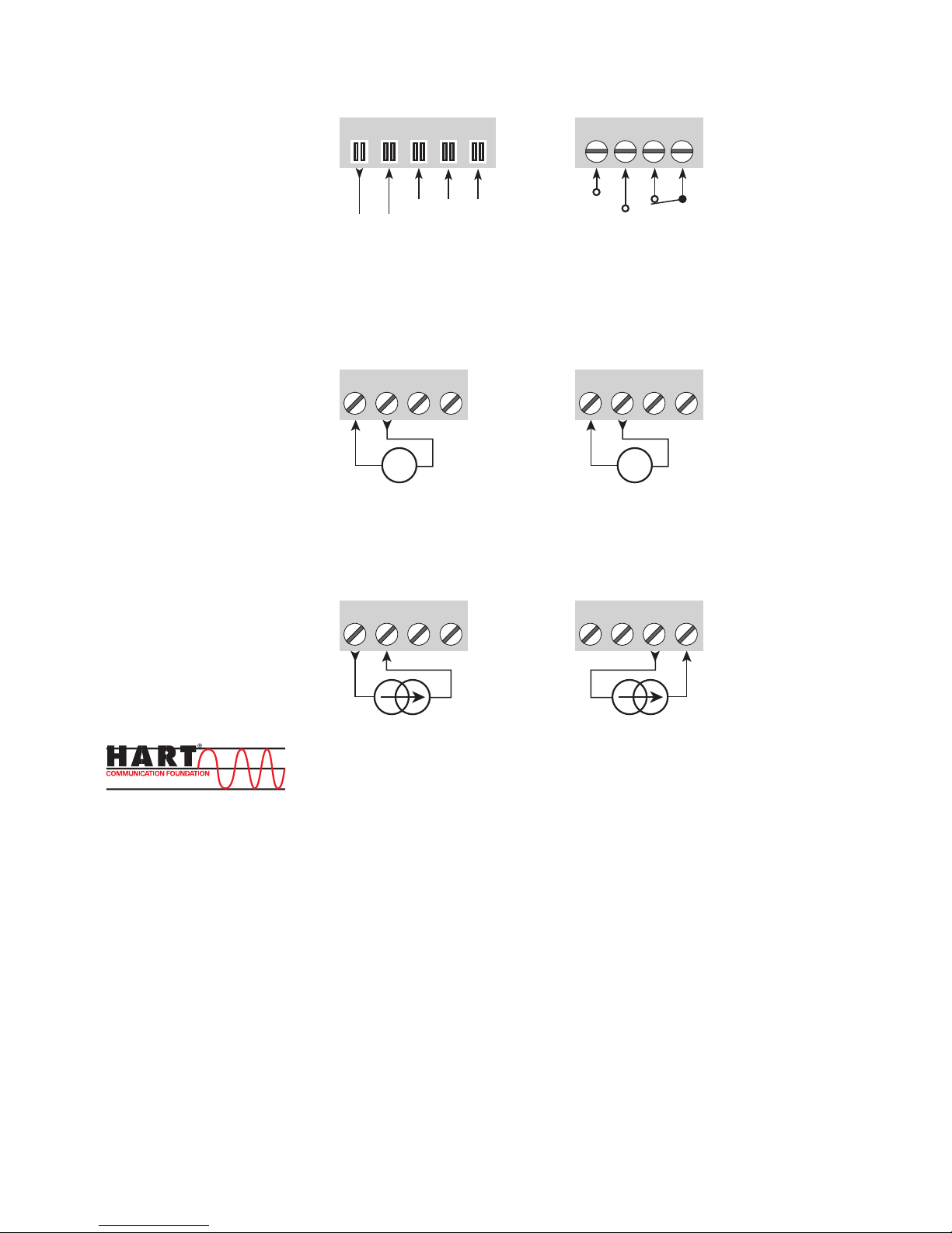
Connections ............................................................................................ 13
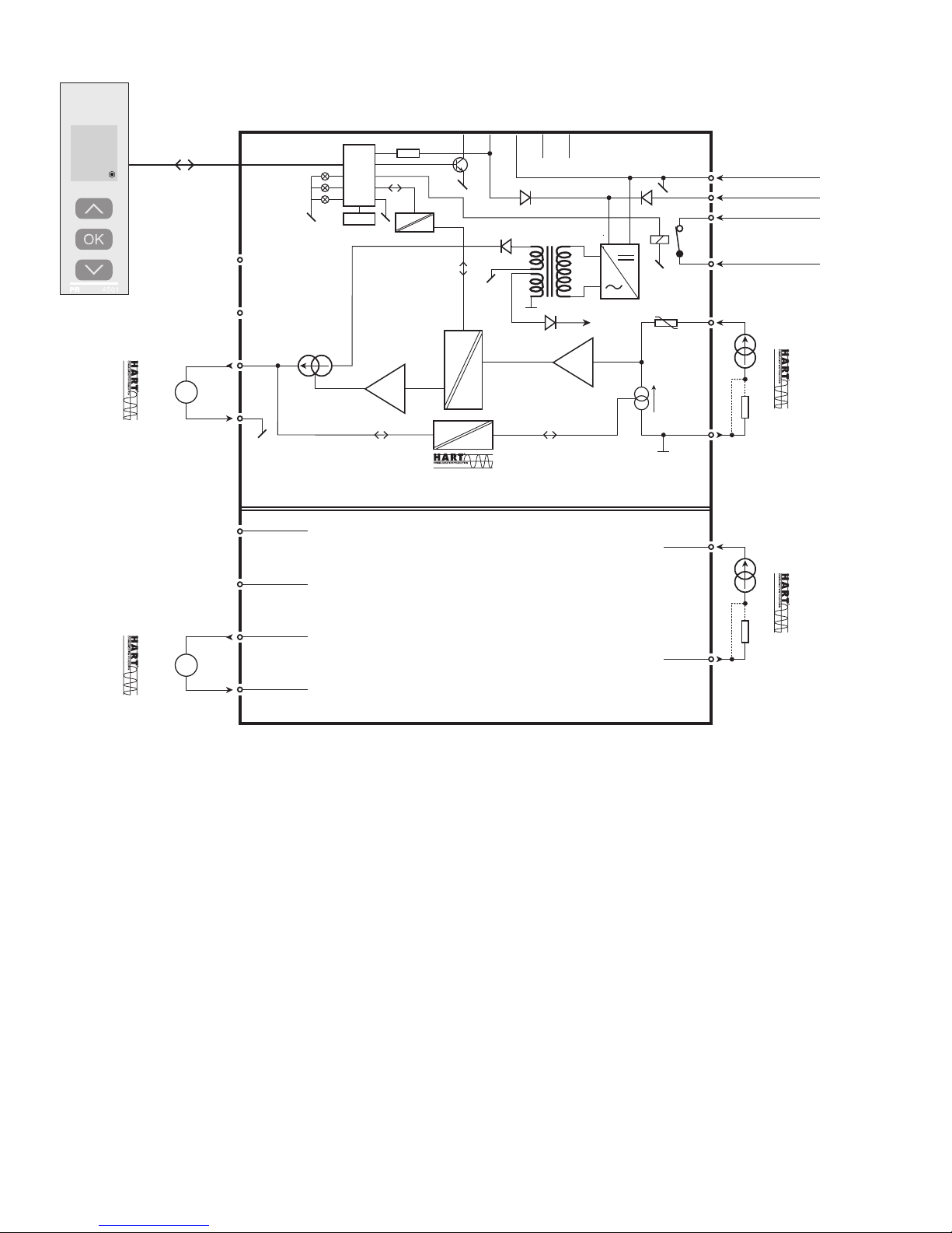
Block diagram........................................................................................... 14
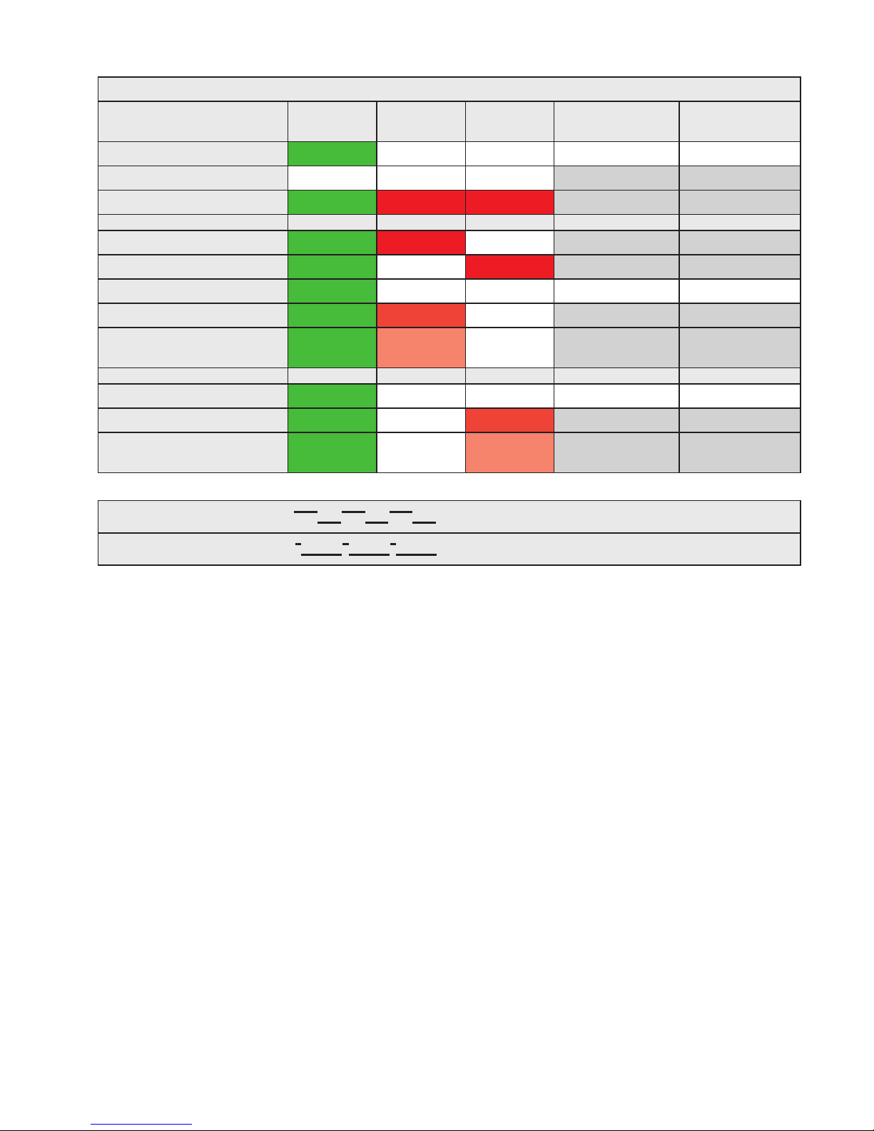
Signal error indications without display front .............................................................. 15
Configuration / operating the function keys ............................................................... 16
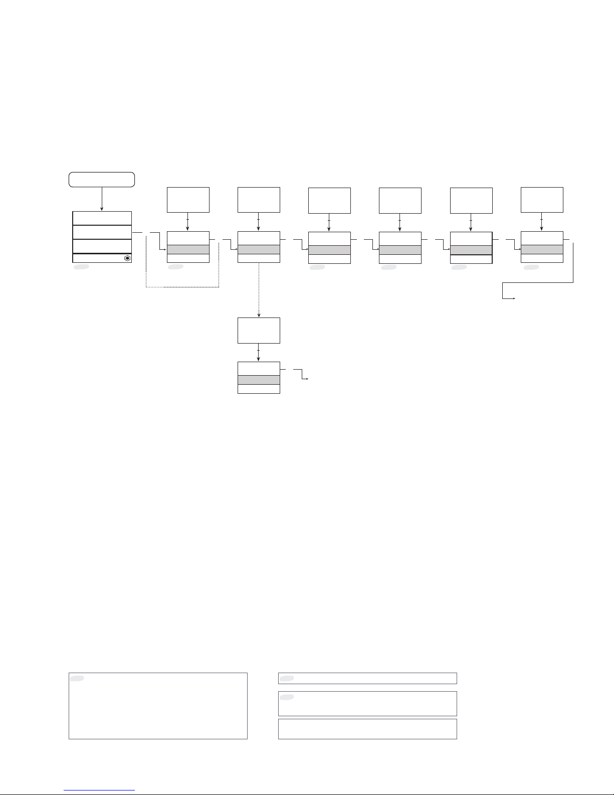
Routing diagram ........................................................................................ 17
Routing diagram, advanced settings (ADV.SET) ............................................................ 18
Help text overview ...................................................................................... 19
ATEX Installation Drawing................................................................................ 20
IECEx Installation Drawing ............................................................................... 22
FM Installation Drawing.................................................................................. 24
Desenho de instalaçao INMETRO ......................................................................... 26
Document history ....................................................................................... 28
Page 4
4 9107 - Product version 9107-002
Warning
The following operations should only be carried out on a disconnected device and under ESD-safe
conditions:
General mounting, wire connection and disconnection.
Troubleshooting the device.
Repair of the device and replacement of circuit breakers must be done by PR electronics A/S only.
Warning
Do not open the front plate of the device as this will cause damage to the connector for the display /
programming front PR 4511/4501.
This device contains no DIP-switches or jumpers.
Symbol identification
Triangle with an exclamation mark: Read the manual before installation and commissioning of the
device in order to avoid incidents that could lead to personal injury or mechanical damage. Warning/
demand. Potentially lethal situations.
The CE mark proves the compliance of the device with the essential requirements of the directives.
The double insulation symbol shows that the device is protected by double or reinforced insulation.
Ex devices have been approved acc. to the ATEX directive for use in connection with installations in
explosive areas. See installation drawings in appendix.
Safety instructions
Definitions
Hazardous voltages have been defined as the ranges: 75 to 1500 Volt DC, and 50 to 1000 Volt AC.
Technicians are qualified persons educated or trained to mount, operate, and also trouble-shoot technically correct and in
accordance with safety regulations.
Operators, being familiar with the contents of this manual, adjust and operate the knobs or potentiometers during normal
operation.
Receipt and unpacking
Unpack the device without damaging it and check whether the device type corresponds to the one ordered. The packing
should always follow the device until this has been permanently mounted.
Environment
Avoid direct sun light, dust, high temperatures, mechanical vibrations and shock, and rain and heavy moisture. If necessary,
heating in excess of the stated limits for ambient temperatures should be avoided by way of ventilation.
The device must be installed in pollution degree 2 or better.
The device is designed to be safe at least under an altitude up to 2 000 m.
Page 5

9107 - Product version 9107-002 5
Mounting
Only technicians, who are familiar with the technical terms, warnings, and instructions in the manual and who are able to
follow these, should connect the device. Should there be any doubt as to the correct handling of the device, please contact
your local distributor or, alternatively,
PR electronics A/S
www.prelectronics.com
The use of stranded wires is not permitted for mains wiring except when wires are fitted with cable ends.
Descriptions of input / output and supply connections are shown in the block diagram and on the side label.
The device is provided with field wiring terminals and shall be supplied from a Power Supply having double / reinforced
insulation. A power switch shall be easily accessible and close to the device. The power switch shall be marked as the
disconnecting unit for the device.
For installation on Power Rail 9400 the power is supplied by Power Control Unit 9410.
Year of manufacture can be taken from the first two digits in the serial number.
Calibration and Adjustment
During calibration and adjustment, the measuring and connection of external voltages must be carried out according to the
specifications of this manual. The technician must use tools and instruments that are safe to use.
Normal operation
Operators are only allowed to adjust and operate devices that are safely fixed in panels, etc., thus avoiding the danger of
personal injury and damage. This means there is no electrical shock hazard, and the device is easily accessible.
Cleaning
When disconnected, the device may be cleaned with a cloth moistened with distilled water.
Liability
To the extent the instructions in this manual are not strictly observed, the custom er cannot advance a demand against PR
electronics A/S that would otherwise exist according to the concluded sales agreement.
How to demount system 9000
Picture 1:
By lifting the bottom lock, the device is detached from the DIN rail.
Page 6

6 9107 - Product version 9107-002
Application
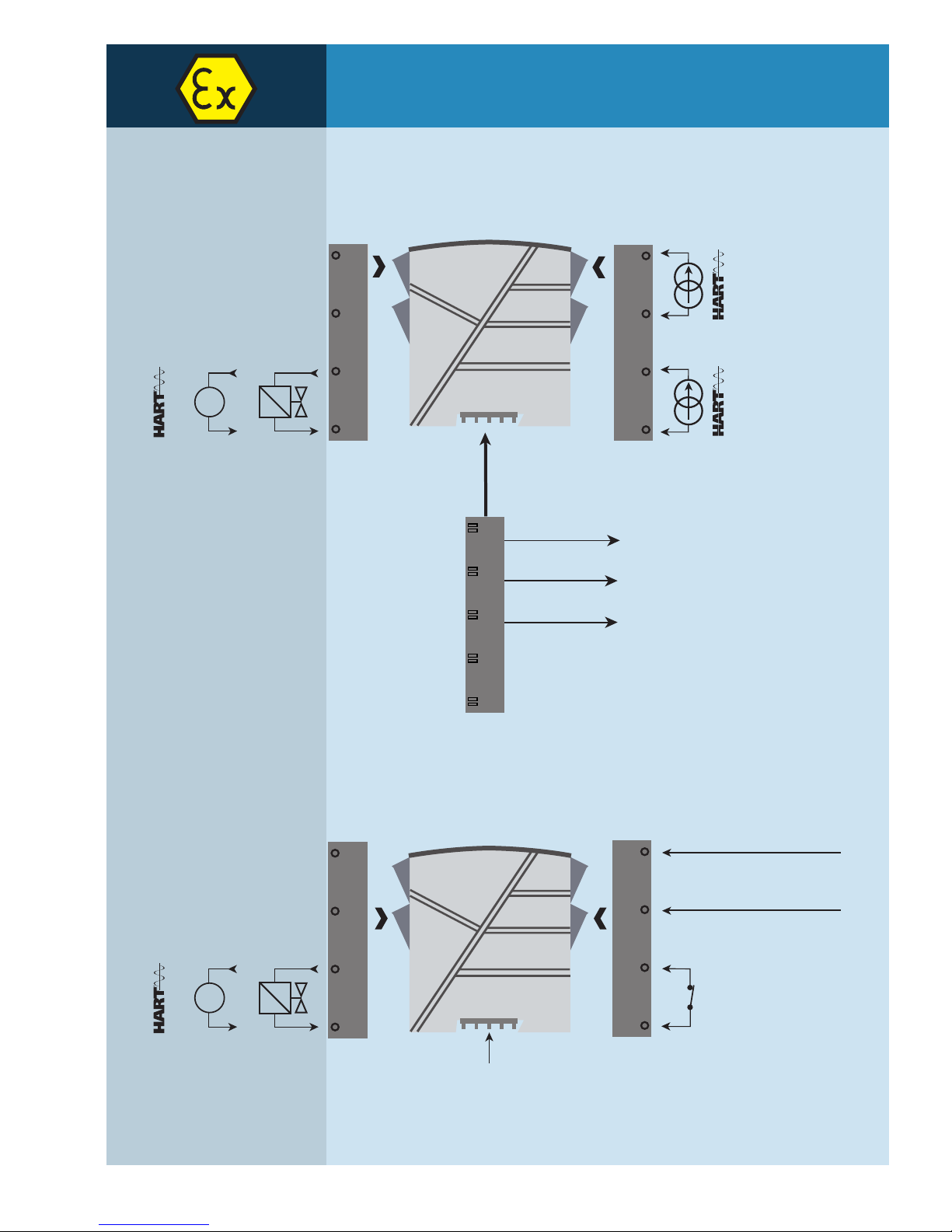
• 9107B is a 1- or 2-channel isolated 1:1 driver barrier for intrinsic safety applications.
• Operation and drive control of I/P converters, valves and indicators mounted in the hazardous area.
• Operation of HART devices is possible as the unit transmits HART communication signals bi-directionally.
• 9107B can be mounted in the safe area or in zone 2 / Cl. 1, div. 2 and transmit signals to zone 0, 1, 2 and zone 20, 21, 22
including mining / Class I/II/III, Div. 1, Gr. A-G.
• The PR 4511/4501 display the process value for each channel and can be used to define high and low limits for detection
of loop current level. If these limits are exceeded, the status relay will activate.
• Dual channel versions can be used for signal splitter applications - 1 in and 2 out.
Advanced features
• The PR 4501 detachable display and the green and red front LEDs indicate operation status for each channel.
• A tag number can be defined for each channel.
• Output line fault detection.
• In the 1-channel version the status relay can be used as a simple limit switch.
Technical characteristics
• High galvanic isolation of 2.6 kVAC.
• High accuracy better than 0.1%.
• Continuous check of vital stored data for safety reasons.
HART transparent driver
9107B
• 24 VDC supply via power rail or connectors
• Fast response time <5 ms
• High active output load 725 Ohm / 20 mA
• Output line fault detection via status relay
• SIL2 certified via Full Assessment according to IEC 61508
Page 7
54
53
52
51
44
43
42
41
44
43
42
41
COMMUNICATION FOUNDATION
+
-
12
11
14
13
mA
+
-
COMMUNICATION FOUNDATION
31
32
33
34
COMMUNICATION FOUNDATION
+
-
mA
+
-
COMMUNICATION FOUNDATION
9107 - Product version 9107-002 7
Applications
Input signals:
Analog, 4...20 mA
Output signals:
Channel 1
Current 4...20 mA
I/P converter
Channel 2
Channel 1
Zone 0, 1, 2,
20, 21, 22, M1 &
Cl. I/II/III, Div. 1
gr. A-G
Zone 2 & Cl. 1, Div. 2, gr. A-D
or Safe Area
Device status
Device status
Supply -
Supply +19.2...31.2 VDC
N.C.
Power connection:
Same power rail as above
Rail, supply +
Power rail
Status relay signal
No connection
No connection
Channel 2
Current 4...20 mA
I/P converter
Rail, supply -
Page 8
OK
4501
1
3
4
2
3
8 9107 - Product version 9107-002
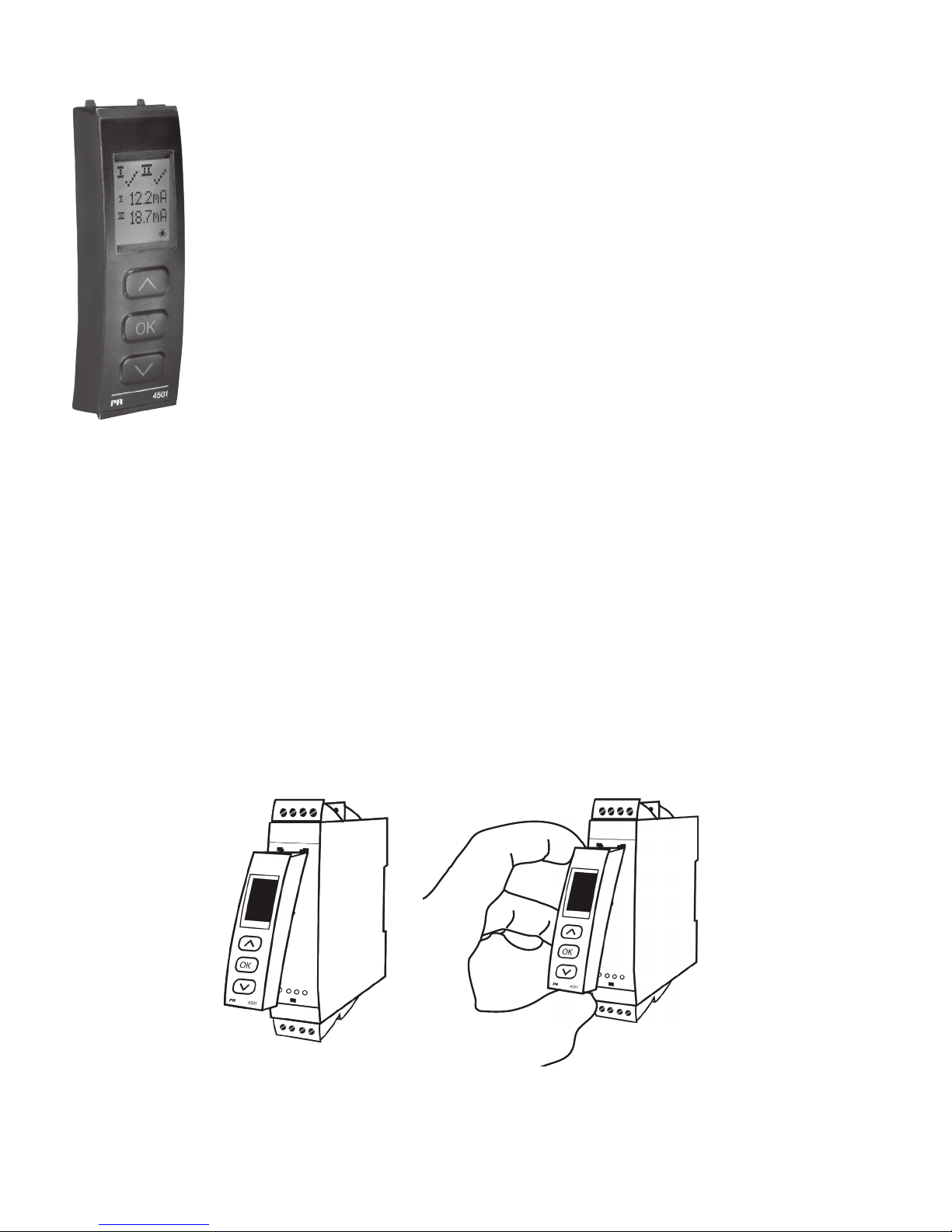
PR 4511/4501 display / programming front
Functionality
The simple and easily understandable menu structure and the explanatory help texts guide you
effortlessly and automatically through the configuration steps, thus making the product very easy to
use. Functions and configuration options are described in the section ”Configuration / operating the
function keys”.
Application
• Communications interface for modification of operational parameters in 9107B.
• When mounted in the process, the display shows process values and device status.
Technical characteristics
• LCD display with 4 lines:
Line 1 (H=5.57 mm) shows status for each channel (OK or error).
Line 2 (H=3.33 mm) shows loop current in mA for channel 1 or tag no.
Line 3 (H=3.33 mm) shows loop current in mA for channel 2 or tag no.
Line 4 shows communications status.
• In order to protect the configuration against unauthorised changes, access to the menus can be
blocked by a password.
Mounting / demounting the PR 4511/4501
1: Insert the tabs of the PR 4511/4501 into the holes at the top of the device.
2: Hinge the PR 4511/4501 down until it snaps into place.
Demounting of the PR 4511/4501
3: Push the release button on the bottom of the PR 4511/4501 and hinge the the PR 4511/4501 out and up.
4: With the PR 4511/4501 hinged up, remove from holes at the top of the device.
Page 9
9107 - Product version 9107-002 9
Accessories
4501 = Display / programming front
4511 = Communication enabler
9400 = Power rail
9404 = Module stop for rail
9410 = Power control unit
9421 = Power supply 24 V - Ex nA nC
Technical data
Environmental conditions:
Specifications range. . . . . . . . . . . . . . . . . . . . . . . . . . . . . . . . . . -20°C to +60°C
Storage temperature . . . . . . . . . . . . . . . . . . . . . . . . . . . . . . . . . -20°C to +85°C
Calibration temperature. . . . . . . . . . . . . . . . . . . . . . . . . . . . . . . . 20...28°C
Relative humidity . . . . . . . . . . . . . . . . . . . . . . . . . . . . . . . . . . . < 95% RH (non-cond.)
Protection degree . . . . . . . . . . . . . . . . . . . . . . . . . . . . . . . . . . . IP20
Installation in . . . . . . . . . . . . . . . . . . . . . . . . . . . . . . . . . . . . . . Pollution degree 2 & overvoltage category II.
Mechanical specifications:
Dimensions (HxWxD) . . . . . . . . . . . . . . . . . . . . . . . . . . . . . . . . . 109 x 23.5 x 104 mm
Dimensions (HxWxD) w/ 4501/4511. . . . . . . . . . . . . . . . . . . . . . . . 109 x 23.5 x 116 / 131 mm
Weight approx. . . . . . . . . . . . . . . . . . . . . . . . . . . . . . . . . . . . . . 250 g
Weight incl. 4501/4511 (approx.). . . . . . . . . . . . . . . . . . . . . . . . . . 265 g / 280 g
DIN rail type. . . . . . . . . . . . . . . . . . . . . . . . . . . . . . . . . . . . . . . DIN EN 60715 - 35 mm
Wire size. . . . . . . . . . . . . . . . . . . . . . . . . . . . . . . . . . . . . . . . . 0.13...2.08 mm
2
/ AWG 26...14 stranded wire
Screw terminal torque. . . . . . . . . . . . . . . . . . . . . . . . . . . . . . . . . 0.5 Nm
Vibration. . . . . . . . . . . . . . . . . . . . . . . . . . . . . . . . . . . . . . . . . IEC 60068-2-6
2...13.2 Hz . . . . . . . . . . . . . . . . . . . . . . . . . . . . . . . . . . . . . . ±1 mm
13.2...100 Hz . . . . . . . . . . . . . . . . . . . . . . . . . . . . . . . . . . . . . ±0.7 g
Common electrical specifications:
Supply voltage . . . . . . . . . . . . . . . . . . . . . . . . . . . . . . . . . . . . . 19.2...31.2 VDC
Fuse . . . . . . . . . . . . . . . . . . . . . . . . . . . . . . . . . . . . . . . . . . . 1.25 A SB / 250 VAC
Max. required power is the maximum power needed at terminals 31 and 32.
Max. power dissipation is the maximum power dissipated by the device.
If the 9107 is used with the 4511/4501, then add 40 mW to the max. power dissipation and 70 mW to the max. required power for each
device with the 4511/4501.
Isolation - test / working:
Input to any. . . . . . . . . . . . . . . . . . . . . . . . . . . . . . . . . . . . . . 2.6 kVAC / 300 VAC reinforced isolation
Analog output to supply . . . . . . . . . . . . . . . . . . . . . . . . . . . . . . 2.6 kVAC / 300 VAC reinforced isolation
Status relay to supply. . . . . . . . . . . . . . . . . . . . . . . . . . . . . . . . 1.5 kVAC / 150 VAC reinforced isolation
Order
Example : 9107BB
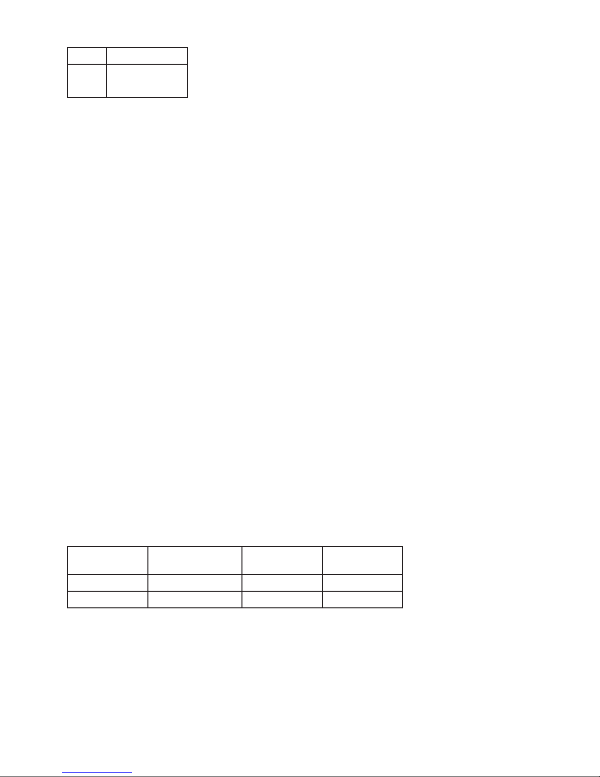
Type Unit channels
9107B Single
Double
: A
: B
Typ e Description
Max. power
dissipation
Max. required
power
9107BA 1 channel ≤ 1.0 W ≤ 1.0 W
9107BB 2 channels ≤ 1.8 W ≤ 1.8 W
Page 10
10 9107 - Product version 9107-002
Communications interface . . . . . . . . . . . . . . . . . . . . . . . . . . . . . . Communication enabler 4511 /
Programming front 4501
Signal dynamics, input /output . . . . . . . . . . . . . . . . . . . . . . . . . . . Analog signal chain
HART bi-directional communication frequency range . . . . . . . . . . . . . . 0.5...7.5 kHz
Signal / noise ratio. . . . . . . . . . . . . . . . . . . . . . . . . . . . . . . . . . . > 60 dB
Response time (0...90%, 100...10%) . . . . . . . . . . . . . . . . . . . . . . . . < 5 ms
Eect of supply voltage change on output (nom. 24 VDC) . . . . . . . . . . . < ±10 µA
Current input:
Measurement range . . . . . . . . . . . . . . . . . . . . . . . . . . . . . . . . . . 3.5...23 mA
Sensor error detection:
Loop break 4...20 mA . . . . . . . . . . . . . . . . . . . . . . . . . . . . . . . . < 1 mA
Input voltage drop:
Supplied unit . . . . . . . . . . . . . . . . . . . . . . . . . . . . . . . . . . . . . < 2 V @ 23 mA
Non-supplied unit . . . . . . . . . . . . . . . . . . . . . . . . . . . . . . . . . . < 4 V @ 23 mA
Ex barrier data:
Uo. . . . . . . . . . . . . . . . . . . . . . . . . . . . . . . . . . . . . . . . . . . . . 28 V
Io . . . . . . . . . . . . . . . . . . . . . . . . . . . . . . . . . . . . . . . . . . . . . 93 mA
Po. . . . . . . . . . . . . . . . . . . . . . . . . . . . . . . . . . . . . . . . . . . . . 0.65 W
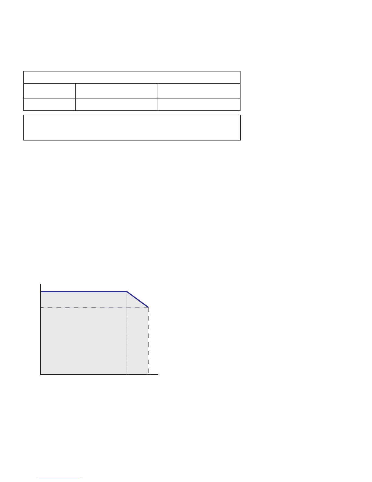
Current output:
Signal range. . . . . . . . . . . . . . . . . . . . . . . . . . . . . . . . . . . . . . . 3.5...23 mA
Load . . . . . . . . . . . . . . . . . . . . . . . . . . . . . . . . . . . . . . . . . . . ≤ 725 Ω
Load stability . . . . . . . . . . . . . . . . . . . . . . . . . . . . . . . . . . . . . . ≤ 0.01% of span / 100 Ω
Current limit. . . . . . . . . . . . . . . . . . . . . . . . . . . . . . . . . . . . . . . ≤ 28 mA
725 Ω
630 Ω
0 Ω
20 mA0 mA 23 mA
Load
Output Current
Output Compliance
of span = normal measurement range 4...20 mA
EMC - immunity influence. . . . . . . . . . . . . . . . . . . . . . . . . < ±0.5% of span
Extended EMC immunity:
NAMUR NE 21, A criterion, burst . . . . . . . . . . . . . . . . . . . . < ±1% of span
Accuracy values
Input type Absolute accuracy Temperature coecient
mA ≤ ±16 ≤ ±1.6 μA /
Page 11

9107 - Product version 9107-002 11
Status relay output terminal 33-34:
Relay function . . . . . . . . . . . . . . . . . . . . . . . . . . . . . . . . . . . . . N.C.
Programmable low setpoint . . . . . . . . . . . . . . . . . . . . . . . . . . . . . 0...29.9 mA
Programmable high setpoint . . . . . . . . . . . . . . . . . . . . . . . . . . . . . 0...29.9 mA
Hysteresis for setpoints . . . . . . . . . . . . . . . . . . . . . . . . . . . . . . . 0.1 mA
Max. voltage . . . . . . . . . . . . . . . . . . . . . . . . . . . . . . . . . . . . . . 110 VDC / 125 VAC
Max. current. . . . . . . . . . . . . . . . . . . . . . . . . . . . . . . . . . . . . . . 0.3 ADC / 0.5 AAC
Max. voltage - hazardous installation. . . . . . . . . . . . . . . . . . . . . . . . 32 VDC / 32 VAC
Max. current - hazardous installation . . . . . . . . . . . . . . . . . . . . . . . . 1 ADC / 0.5 AAC
Observed authority requirements:
EMC. . . . . . . . . . . . . . . . . . . . . . . . . . . . . . . . . . . . . . . . . . . . 2014/30/EU
LVD . . . . . . . . . . . . . . . . . . . . . . . . . . . . . . . . . . . . . . . . . . . . 2014/35/EU
ATE X . . . . . . . . . . . . . . . . . . . . . . . . . . . . . . . . . . . . . . . . . . . 2014/34/EU
RoHS . . . . . . . . . . . . . . . . . . . . . . . . . . . . . . . . . . . . . . . . . . . 2011/65/EU
Approvals:
Det Norske Veritas, Ships & Oshore. . . . . . . . . . . . . . . . . . . . . . . . Stand. f. Certific. No. 2.4
ClassNK . . . . . . . . . . . . . . . . . . . . . . . . . . . . . . . . . . . . . . . . . TA18527M
c UL us, Standard for Safety . . . . . . . . . . . . . . . . . . . . . . . . . . . . . UL 61010-1
EAC . . . . . . . . . . . . . . . . . . . . . . . . . . . . . . . . . . . . . . . . . . . . TR-CU 020/2011
I.S. / Ex approvals:
ATE X . . . . . . . . . . . . . . . . . . . . . . . . . . . . . . . . . . . . . . . . . . . DEKRA 11ATEX0247 X
IECEx . . . . . . . . . . . . . . . . . . . . . . . . . . . . . . . . . . . . . . . . . . . IECEx DEK 11.0088X
c FM us. . . . . . . . . . . . . . . . . . . . . . . . . . . . . . . . . . . . . . . . . . FM16US0465X / FM16CA0213X
INMETRO . . . . . . . . . . . . . . . . . . . . . . . . . . . . . . . . . . . . . . . . DEKRA 16.0002 X
CCOE . . . . . . . . . . . . . . . . . . . . . . . . . . . . . . . . . . . . . . . . . . . P337349/2
EAC Ex TR-CU 012/2011 . . . . . . . . . . . . . . . . . . . . . . . . . . . . . . . RU C-DK.GB08.V.00410
Functional Safety:
SIL2 Certified & Fully Assessed acc. to IEC 61508
SFF> 60% - type A component
Page 12
12 9107 - Product version 9107-002
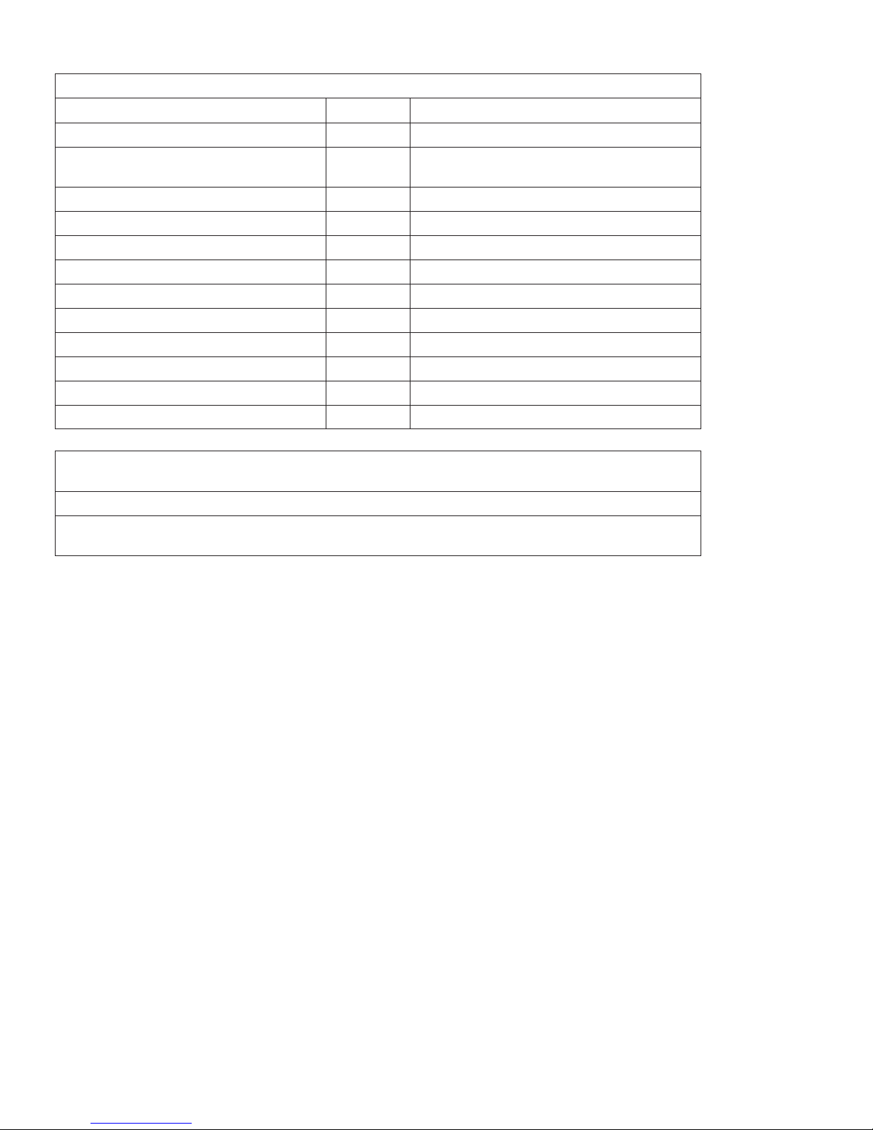
Visualisation in the 4511/4501 of hardware/software error
Readout at hardware error
Error search Readout Cause
Communications test 4511/4501 and 9107 NO.CO Connection error
EEprom error - check configuration FL.ER
Configuration error or CRC mismatch, recovery
configuration is loaded
User error II ! / II ! Loop limit exceeded
User error II ! / II ! Loop error
EEprom error - check configuration EE.ER / IE.ER Invalid configuration (CRC or data)
Hardware error SU.ER Supply error
Hardware error RA.ER RAM error
Hardware error FL.ER Flash error
Hardware error IN.ER Initialization error
Hardware error C1.ER Hardware error - channel 1
Hardware error C2.ER Hardware error - channel 2
Hardware error DE.ER General error
! All error indications in the display flash once per second. The help text explains the error.
In case of cable fault the backlight also flashes. This can be reset by pressing the 3 key.
Errors affecting both channels are shown as error on channel 1 - and the line showing channel 2 is blank.
Hardware error can be reset in two ways. Either step through the menus (if the other channel is to stay in
operation) or power cycle the device.
Page 13
9107 - Product version 9107-002 13
Connections
51
5352
54
+
-
mA
41
4342
44
+
-
mA
11
1312
14
+
-
11
1312
14
+-
31 32 3433
91 92 93 94 95
Inputs:
CurrentCurrent
Current
Current
Channel 1
Channel 2 Channel 2
Ex / I.S: outputs:
Channel 1
Supply and
status relay
Power rail
connections
NC = no connection
Supply -
Supply +
Supply -
Supply +
NC
NC
Error signal
HART communication is possible directly on the input and output terminals if the output load impedance is
> 250 Ohm & < 725 Ohm or if the input loop resistance is higher than 250 Ohm.
Page 14
TAG-2
TAG- 1
I+
31
14
12
11
9107B
32
34
33
FLASH
CPU
44
43
42
41
54
53
52
51
13
mA
1 V
250 Ω
V+
mA
I+
250 Ω
NC*NC*
+
-
+
-
14 9107 - Product version 9107-002
Block diagram
Status relay N.C.
Status relay N.C.
Supply -
Supply +24 VDC
Input, Gnd.
Channel 2
Channel 1
Current, 4...20 mA
Current, 4...20 mA
Output, Gnd.
Output, Gnd.
Input, Gnd.
* NC = No connection
Power rail connections
Channel 2 is identical to channel 1
Device status, Green
Ch. 1 status, Red
Ch. 2 status, Red
Supply +
Supply -
Page 15
9107 - Product version 9107-002 15
Signal error indications without display front
List of LED and error signal indications
Condition Green LED
Ch. 1:
Red
Ch. 2:
Red
Status relay, N.C.
Power rail
signal status
Device OK Blinking OFF OFF Energized OFF
No supply OFF OFF OFF De-energized ON
Device defective Blinking ON ON De-energized ON
Ch. 1 defective (ch. 2 OK) Blinking ON OFF De-energized ON
Ch. 2 defective (ch. 1 OK) Blinking OFF ON De-energized ON
Channel 1, signal OK Blinking OFF OFF Energized OFF
Ch. 1, signal limit exceeded Blinking Blinking OFF De-energized ON (if activated)
Ch. 1, fixed loop break limit
exceeded
Blinking Flashing OFF De-energized
ON
(if activated)
Channel 2, signal OK Blinking OFF OFF Energized OFF
Ch. 2, signal limit exceeded Blinking OFF Blinking De-energized ON (if activated)
Ch. 2, fixed loop break limit
exceeded
Blinking OFF Flashing De-energized
ON
(if activated)
Blinking : 50% ON and 50% OFF
Flashing : 8% ON and 92% OFF
Page 16

16 9107 - Product version 9107-002
Configuration / operating the function keys
Documentation for routing diagram.
In general
When configuring the 9107, you will be guided through all parameters and you can choose the settings which fit the
application. For each menu there is a scrolling help text which is automatically shown in line 3 on the display.
Configuration is carried out by use of the 3 function keys:
1 will increase the numerical value or choose the next parameter
2 will decrease the numerical value or choose the previous parameter
3 will save the chosen value and proceed to the next menu
When configuration is completed, the display will return to the default state 1.0. Pressing and holding 3 will return to the
previous menu or return to the default state (1.0) without saving the changed values or parameters.
If no key is activated for 1 minute, the display will return to the default state (1.0) without saving the changed values or
parameters.
Further explanations
Password protection: Programming access can be blocked by assigning a password. The password is saved in the device in
order to ensure a high degree of protection against unauthorised modifications to the configuration. Default password 2008
allows access to all configuration menus.
Loop limits
In the menus LO.LIM and HI.LIM you can choose the current values which will trigger a loop error alarm from the status relay.
The NAMUR NE43 limits are selected by setting LO.LIM at 3.6 mA and HI.LIM at 21 mA. The selected limits are identical for
both channels. This function can be deactivated by selecting limits outside the range 3.5...23 mA. Alternatively, the status
relay can be used as a simple limit switch in the 1-channel version.
The loop break limit is fixed <= 1 mA. If this limit is exceeded, the status relay will be de-energized.
Signal and sensor error indication via display front 4511/4501
Sensor error (loop break) is shown in line 1 on the display by flashing and . The actual mA value is also shown followed by
an explanatory text. Channel 1 is shown in line 2 and channel 2 is shown in line 3 on the display.
Line 4 on the display shows the condition of the COM (flashing bullet) indicating correct functioning of 4511/4501.
Advanced functions
The unit gives access to a number of advanced functions which can be reached by answering “Yes” to the point “ADV.SET”.
Display setup: Here you can adjust the brightness contrast and the backlight. Setup of tag numbers with 5 alphanumerics.
Selection of functional readout in line 2 and 3 on the display - choose between readout of loop current or tag no. When
selecting ”ALT” the readout toggles between loop current and tag no.
Password: Here you can choose a password between 0000 and 9999 in order to protect the unit against unauthorised
modifications to the configuration. The unit is delivered default without password.
Language: In the menu ”LANG” you can choose between 7 different language versions of help texts that will appear in the
menu. You can choose between UK, DE, FR, IT, ES, SE and DK.
Power rail: In the menu ”RAIL” you can choose if a signal is transmitted to the central surveillance in the PR 9410 power
control unit when the signal limits are exceeded.
Safety Integrity Level (SIL): See Safety Manual for details.
Page 17
0000
PASSW.
Txt 1
0000
9999
NO
ADV.SET
Txt 2
NO
YES
1 21 2
*1.1
*1.2
20.0
12.2
YES
ADV.SET
Txt 2
NO
YES
1 2
23.0
HI.LIM1
Txt 4
0.0
29.9
1 2
3.5
LO.LIM1
Txt 3
0.0
29.9
1 2
23.0
HI.LIM2
Txt 4
0.0
29.9
1 2
3.5
LO.LIM2
Txt 3
0.0
29.9
1 2
3 3 33
3
3
3
3
*1.2 *1.2*1.2
*1.0
9107 - Product version 9107-002 17
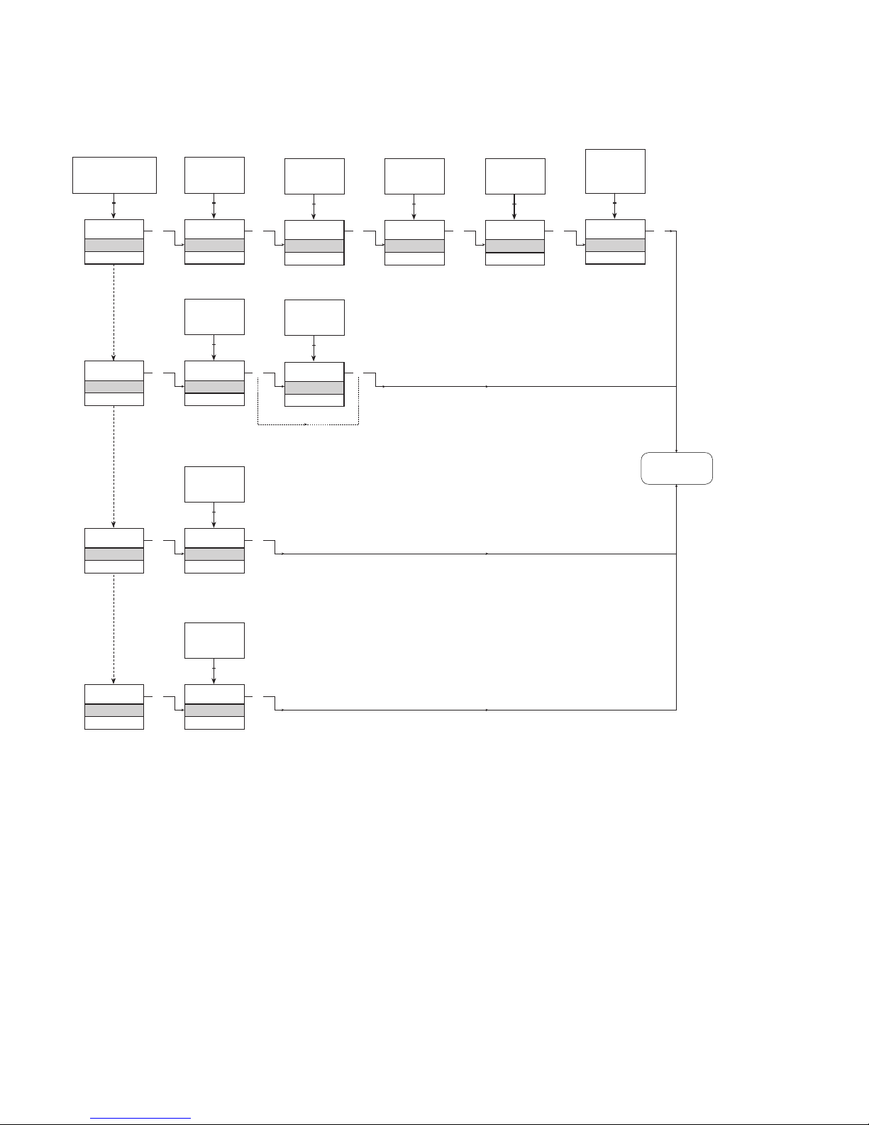
Routing diagram
If no key is activated for 1 minute, the display will return to the default state 1.0 without saving configuration changes.
1 Increase value / choose next parameter
2 Decrease value / choose previous parameter
3 Save the chosen value and proceed to the next menu
Hold 3 Back to previous menu / return to menu 1.0 without saving.
To default
state 1.0
Continued on the page
Routing diagram ADV.SET
*1.1
Only if password-protected.
*1.0
Default state.
Line 1 shows status for channel 1 and channel 2
Line 2 shows analog value or tag no. for channel 1.
If the loop limit is exceeded (LO.LIM and HI.LIM) the analog
value is shown for 5 s followed by txt 18.
In case of loop break, 0.0 is shown for 5 s. followed by txt
19.
Line 3 shows the same as line 2, only for channel 2.
Line 4 shows status for communication.
*1.2
Loop current limits (identical for both channels) can be
deactivated by selecting values outside the range
3.5...23 mA.
Line 1 symbols:
= OK. Flashing
= error.
Power up
Page 18
DISP
SETUP
Txt 6
DISP, PASS,
LANG, RAIL
NO
CONTRA
Txt 9
9
0
1 21 2
TAG1
TAGNO
Txt 11
9
A
1 2
9
LIGHT
Txt 10
9
0
1 2
LOOP
DISP
Txt 12
ALT
TAG
LOOP
1 2
TAG2
TAGNO
Txt 11
9
A
1 2
3 3 333 3
PASS
SETUP
Txt 6
YES
EN.PASS
Txt 15
YES
NO
1 2
0000
NEW.PAS
Txt 16
9999
0000
1 2
333
NO
LANG
SETUP
Txt 6
UK
LANGUA
Txt 17
9
0
1 2
33
RAIL
SETUP
Txt 6
YES
RAIL.EN
Txt 5
YES
NO
1 2
33
18 9107 - Product version 9107-002
Routing diagram, advanced settings (ADV.SET)
To default
state 1.0
Page 19

9107 - Product version 9107-002 19
Help text overview
[01]
[02]
[03]
[04]
[05]
[06]
[09]
[10]
[11]
[12]
[15]
[16]
[17]
[18]
[19]
[20]
[21]
[22]
Set correct password [PASS]
Enter advanced setup [ADV.SET]
Set low limit for loop error detection [LO.LIM1] [LO.LIM2]
Set high limit for loop error detection [HI.LIM1] [HI.LIM2]
Enable rail status signal output? [RAIL.ER]
Enter display setup [SETUP]
Enter password setup [SETUP]
Enter language setup [SETUP]
Enter rail setup [SETUP]
Adjust LCD contrast [CONTRA]
Adjust LCD backlight [LIGHT]
Write a 5-character tag no. [TAGNO1] [TAGNO2]
Show loop values in display
Show Tag no. in display
Alternate shown information in display
Enable password protection [EN.PASS]
Set new password [NEW.PAS]
Select language [LANGUA]
Loop signal limit exceeded
Loop wire breakage
No communication - check connections
Eeprom error - check configuration
Hardware error
Page 20
20 9107 - Product version 9107-002
9107QA01
LERBAKKEN 10, 8410 RØNDE DENMARK
Revision date:
2013-09-11
Version Revision
V3 R0
Prepared by:
PB
Page:
1/2
ATEX Installation drawing
For safe installation of 9107B the following must be observed. The module shall only be
installed by qualified personnel who are familiar with the national and international laws,
directives and standards that apply to this area.
Year of manufacture can be taken from the first two digits in the serial number.
For Installation in Zone 2 the following must be observed.
The 4501 programming module is to be used solely with PRelectronics modules. It is
important that the module is undamaged and has not been altered or modified in any way.
Only 4501 modules free of dust and moisture shall be installed.
9107BA: 1 channel
HART
-transparent driver
9107BB: 2 channel HART
-transparent driver
ATEX Certificate: ………………………………………………..…. DEKRA 11 ATEX0247X
Marking
Standards EN 60079-0 : 2012, EN 60079-11 : 2012, EN 60079-15 : 2010
EN 60079-26 : 2007
Installation notes:
Install in pollution degree 2, overvoltage category II as defined in EN 60664-1
Do not separate connectors when energized and an explosive gas mixture is present.
Do not mount or remove modules from the Power Rail when an explosive gas mixture is present.
Disconnect power before servicing.
The wiring of unused terminals is not allowed.
In type of protection [Ex ia Da] the parameters for intrinsic safety for gas group IIB are applicable.
For installation in Zone 2, the module shall be installed in an enclosure in type of protection Ex n or
Ex e, providing a degree of protection of at least IP54. Cable entry devices and blanking elements
shall fulfill the same requirements.
For installation on Power Rail in Zone 2, only Power Rail type 9400 supplied by Power Control Unit
type 9410 (Type Examination Certificate KEMA 07ATEX0152 X) is allowed.
II (1) G [Ex ia Ga] IIC/IIB/IIA
II 3 G Ex nA nC IIC T4 Gc
II (1) D [Ex ia Da] IIIC
I (M1) [Ex ia Ma] I
Status Relay. terminal (33,34) Zone 2 Installation
Voltage max: 125 VAC / 110 VDC 32 VAC / 32 VDC
Power max: 62.5 VA / 32 W 16 VA / 32 W
Current max: 0.5 A AC / 0.3 ADC 0.5 A AC / 1ADC
Supply terminal (31,32)
Voltage : 19.2 – 31.2 VDC
Page 21
9107 - Product version 9107-002 21
9107QA01
LERBAKKEN 10, 8410 RØNDE DENMARK
Revision date:
2013-09-11
Version Revision
V3 R0
Prepared by:
PB
Page:
2/2
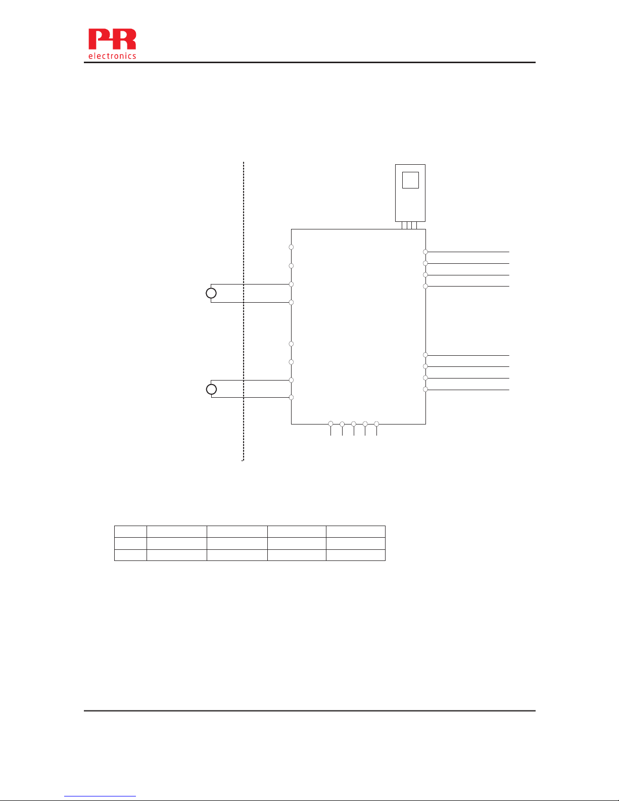
Hazardous area Non Hazardous area
Zone 0,1,2, 20, 21, 22 or Zone 2
CH1 (terminal 41,42)
CH2 (terminal 51,52)
U
o
: 28 V
I
o
: 93 mA
P
o
: 0.65 W
IIC IIB IIA I
Co.
0.080
F 0.650F 2.15 F
3.76 µF
Lo. 4 mH 16 mH 32 mH 35 mH
-20 ≤Ta ≤ +60ºC
44
43
42
41
54
53
52
51
34
33
32
31
14
13
12
11
9107
CH1
CH2
_
+
+
_
mA
mA
91 92 93 94 95
Power Rail
4501
(terminal 11,12,13,14)
(terminal 31,32,33,34)
(terminal 91,92,93,94,95)
Um: 253 V, max 400 Hz
Page 22
9107QI01
LERBAKKEN 10, 8410 RØNDE DENMARK
Revision date:
2013-09-11
Version Revision
V3 R0
Prepared by:
PB
Page:
1/2
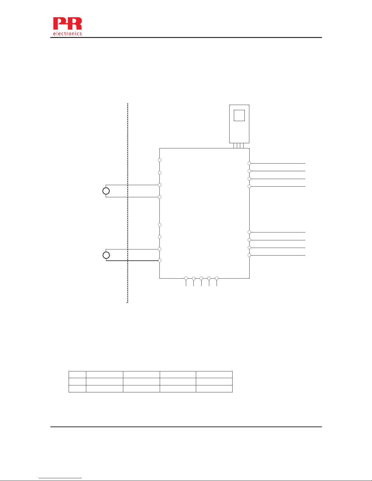
IECEx Installation drawing
For safe installation of 9107B the following must be observed. The module shall only be
Installed by qualified personnel who are familiar with the national and international laws,
directives and standards that apply to this area.
Year of manufacture can be taken from the first two digits in the serial number.
For Installation in Zone 2 the following must be observed.
The 4501 programming module is to be used solely with PRelectronics modules. It is
important that the module is undamaged and has not been altered or modified in any way.
Only 4501 modules free of dust and moisture shall be installed.
9107BA: 1 channel
HART
-transparent driver
9107BB: 2 channel HART
-transparent driver
IECEx Certificate: ………………..IECEx DEK 11.0088X
Marking
Standards IEC60079-15 :2010, IEC60079-11:2011, IEC60079-0: 2011
IEC60079-26: 2006
Installation notes:
Install in pollution degree 2, overvoltage category II as defined in IEC 60664-1.
Do not separate connectors when energized and an explosive gas mixture is present.
Do not mount or remove modules from the Power Rail when an explosive gas mixture is present.
Disconnect power before servicing.
The wiring of unused terminals is not allowed.
In type of protection [Ex ia Da] the parameters for intrinsic safety for gas group IIB are applicable.
For installation in Zone 2, the module shall be installed in an enclosure in type of protection Ex n or
Ex e, providing a degree of protection of at least IP54. Cable entry devices and blanking elements
shall fulfill the same requirements.
For installation on Power Rail in Zone 2, only Power Rail type 9400 supplied by Power Control Unit
type 9410 (Type Examination Certificate KEMA 07ATEX0152) is allowed.
[Ex ia Ga] IIC/IIB/IIA
Ex nA nC IIC T4 Gc
[Ex ia Da] IIIC
[Ex ia Ma] I
Supply terminal (31,32)
Voltage: 19.2 – 31.2 VDC
Status Relay. terminal (33,34) Zone 2 Installation
Voltage max: 125 VAC / 110 VDC 32 VAC / 32 VDC
Power max: 62.5 VA / 32 W 16 VA / 32 W
Current max: 0.5 A AC / 0.3 ADC 0.5 A AC / 1 ADC
22 9107 - Product version 9107-002
Page 23
9107QI01
LERBAKKEN 10, 8410 RØNDE DENMARK
Revision date:
2013-09-11
Version Revision
V3 R0
Prepared by:
PB
Page:
2/2
Hazardous area Non Hazardous area
Zone 0,1,2, 20, 21, 22 or Zone 2
CH1 (terminal 41,42)
CH2 (terminal 51,52)
U
o
: 28 V
I
o
: 93 mA
P
o
: 0.65 W
IIC IIB IIA I
Co.
0.080
F 0.650F 2.15 F
3.76 µF
Lo. 4 mH 16 mH 32 mH 35 mH
-20 ≤Ta ≤ +60ºC
(terminal 11,12,13,14)
(terminal 31,32,33,34)
(terminal 91,92,93,94,95)
Um: 253 V, max. 400 Hz
44
43
42
41
54
53
52
51
34
33
32
31
14
13
12
11
9107
CH1
CH2
_
+
+
_
mA
mA
91 92 93 94 95
Power Rail
4501
9107 - Product version 9107-002 23
Page 24
9107QF01
LERBAKKEN 10, 8410 RØNDE DENMARK
Revision date:
2011-11-02
Version Revision
V2 R0
Prepared by:
PB
Page:
1/2
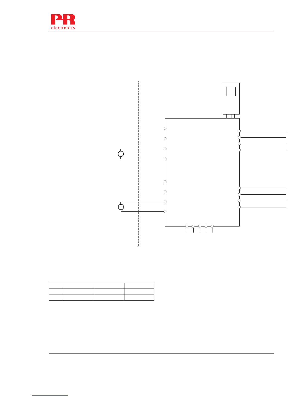
FM Installation drawing
For safe installation of 9107B the following must be observed. The module shall only be
installed by qualified personnel who are familiar with the national and international laws,
directives and standards that apply to this area.
Year of manufacture can be taken from the first two digits in the serial number.
For Installation in Zone 2 the following must be observed.
The 4501 programming module is to be used solely with PRelectronics modules. It is
important that the module is undamaged and has not been altered or modified in any way.
Only 4501 modules free of dust and moisture shall be installed.
9107BA: 1 channel
HART
-transparent driver
9107BB: 2 channel HART
-transparent driver
Installation notes:
In Class I, Division 2 installations, the subject equipment shall be mounted within a tool-secured
enclosure which is capable of accepting one or more of the Class I, Division 2 wiring methods
specified in the National Electrical Code (ANSI/NFPA 70) or Canadian Electrical Code (C22.1).
The equipment shall be installed in an enclosure with a minimum ingress protection rating of IP54
unless the apparatus is intended to be afforded an equivalent degree of protection by location.
The module is galvanically isolated and does not require grounding.
Install in pollution degree 2, overvoltage category II.
Use 60 / 75 ºC copper conductors with wire size AWG: (26-14)
In type of protection “intrinsic safety iD” the parameters for intrinsic safety for gas group IIB are
applicable.
Warning: Substitution of components may impair intrinsic safety.
Warning: To prevent ignition of the explosive atmospheres, disconnect power before servicing
and do not separate connectors when energized and an explosive gas mixture is present.
Warning: Do not install or remove modules from the Power Rail when an explosive gas mixture is
present.
Status Relay. terminal (33,34)
Voltage max: 125 VAC / 110 VDC
Power max: 62,5 VA / 32 W
Current max: 0.5 A AC / 0.3 ADC
Zone 2 installation:
Voltage max: 32 VAC / 32 VDC
Power max: 16 VA / 32 W
Current max: 0.5 A AC / 1 ADC
Supply terminal (31,32)
Voltage: 19.2 – 31.2 VDC
24 9107 - Product version 9107-002
Page 25
9107QF01
LERBAKKEN 10, 8410 RØNDE DENMARK
Revision date:
2011-11-02
Version Revision
V2 R0
Prepared by:
PB
Page:
2/2
CH1 (terminal 41,42)
CH2 (terminal 51,52)
U
o
,Voc: 28 V
I
o
, Isc: 93 mA
P
o
: 0.65 W
IIC or A,B IIB or C,E,F IIA or D,G
Co.
0.08
F 0.650 F 2.15 F
Lo. 4 mH 16 mH 32 mH
-20 ≤Ta ≤ +60ºC
Hazardous Classified Location
Class I / II / III, Division 1, Group A,B,C,D,E,F,G
Class I Zone 0 / 1 / 2 Group IIC, IIB, IIA or
Zone 20 / 21
Unclassified Location or
Hazardous Classified Location
Class I, Division 2 Group A,B,C,D T4
Class I, Zone 2, Group IIC, IIB, IIA T4
Simple Apparatus or
Intrinsic safe apparatus
with entity parameters:
Vmax (Ui) ≥ Vt (Uo)
Imax (Ii) ≥ It (Io)
Pi ≥ Pt (Po)
Ca ≥ C
cable + Ci
La ≥ L
cable + Li
44
43
42
41
54
53
52
51
34
33
32
31
14
13
12
11
9107
CH1
CH2
_
+
+
_
mA
mA
91 92 93 94 95
Power Rail
4501
(terminal 11,12,13,14)
(terminal 31,32,33,34)
(terminal 91,92,93,94,95)
Um: 253 V, max. 400 Hz
9107 - Product version 9107-002 25
Page 26
9107QB01
LERBAKKEN 10, 8410 RØNDE DENMARK
Revision date:
2016-02-10
Version Revision
V3 R0
Prepared by:
PB
Page:
1/2
INMETRO - Desenhos para Instalação
Para instalação segura do 9107B o manual seguinte deve ser observado. O módulo deve
ser instalado somente por profissionais qualificados que estão familiarizados com as leis
nacionais e internacionais, diretrizes e normas que se aplicam a esta área.
Ano de fabricação pode ser obtido a partir dos dois primeiros dígitos do número de série.
Para a instalação na Zona 2 o seguinte deve ser observado. O módulo de programação de
4501, deve ser utilizado apenas com os módulos PRelectronics. É importante que o
módulo esteja intacto e não tenha sido alterado ou modificado de qualquer maneira.
Apenas os módulos 4501 livres de poeira e umidade devem ser instalados.
9107BA: 1 canal
HART® - driver transparente
9107BB: 2 canais HART® - driver transparente
INMETRO Certificado ………… DEKRA 16.0002X
Marcas
Normas:
ABNT NBR IEC 60079-0:2013, ABNT NBR IEC 60079-11:2013,
ABNT NBR IEC 60079-15:2012
Notas de instalação:
Instalação em grau de poluição 2, categoria de sobretensão II conforme definido no IEC 60664-1.
Os circuitos não intrinsecamente seguros só pode ser connectado para sobretensão limitado ao
categoria I/II como definido na IEC 60664-1
Não separe conectores quando energizado ou quando uma mistura de gás explosivo estiver
presente.
Não monte ou remova módulos do trilho de alimentação quando uma mistura explosiva de gás
estiver presente.
Desligue a alimentação antes da manutenção.
A fiação de terminais sem uso não é permitida.
Em tipo de proteção [Ex ia Da] os parâmetros para a segurança intrínseca para grupo de gás IIB
são aplicáveis.
Para a instalação em Zona 2, o módulo deve ser instalado em um invólucro conformidade com o
tipo de proteção ‘Ex n’ ou ‘Ex e’, fornecendo no mínimo grau de proteçao IP54.
Dispositivos de entrada de cabo e elementos de vedação devem cumprir com os mesmos
requisitos.
Para a instalação de trilho de energia na Zona 2, apenas o trilho de alimentação Rail 9400
fornecido pela Unidade de Controle de Potência 9410 é permitido.
[Ex ia Ga] IIC/IIB/IIA
Ex nA nC IIC T4 Gc
[Ex ia Da] IIIC
[Ex ia Ma] I
Terminal de fonte de alimentação (31,32)
Voltagem: 19.2 – 31.2 VDC
Relê de estado terminal (33,34) Instalação Zone 2
Voltagem máx.: 125 VAC / 110 VDC 32 VAC / 32 VDC
Potencia máx.: 62,5 VA / 32 W 16 VA / 32 W
Corrente máx,: 0,5 AAC / 0,3 ADC 0,5 AAC / 1 ADC
26 9107 - Product version 9107-002
Page 27
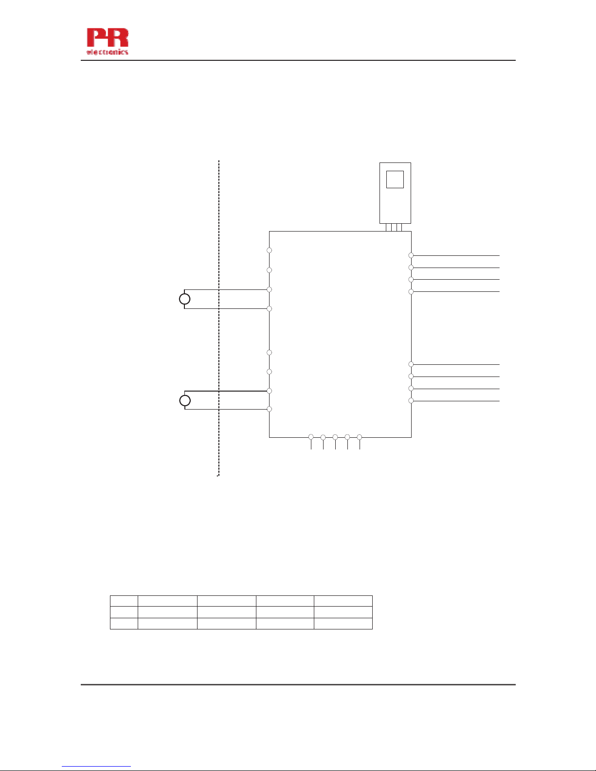
9107QB01
LERBAKKEN 10, 8410 RØNDE DENMARK
Revision date:
2016-02-10
Version Revision
V3 R0
Prepared by:
PB
Page:
2/2
Área de classificada Área de não classificada
Zona 0,1,2, 20, 21, 22 ou Zona 2
CN1 (terminais 41,42)
CN2 (terminais51,52)
U
o
: 28 V
I
o
: 93 mA
P
o
: 0,65 W
IIC IIB IIA I
Co.
0,080
F 0,650F 2,15 F
3,76 µF
Lo. 4 mH 16 mH 32 mH 35 mH
-20 ≤Ta ≤ +60ºC
(terminais: 11,12,13,14)
(terminais: 31,32,33,34)
(terminais: 91,92,93,94,95)
Um: 253 V, máx. 400 Hz
44
43
42
41
54
53
52
51
34
33
32
31
14
13
12
11
9107
CH1
CH2
_
+
+
_
mA
mA
91 92 93 94 95
4501
TRILHO DE ENERGIA
9107 - Product version 9107-002 27
Page 28

28 9107 - Product version 9107-002
Document history
The following list provides notes concerning revisions of this document.
Rev. ID Date Notes
104 1901 Specifications for max. required power added
FM and INMETRO certificate numbers updated
Installation drawings updated
Page 29

We are near you,
all over the world
All our devices are backed by expert service and a 5-year
warranty. With each product you purchase, you receive
personal technical support and guidance, day-to-day
delivery, repair without charge within the warranty period
and easily accessible documentation.
We are headquartered in Denmark, and have offices and
authorized partners the world over. We are a local
business with a global reach. This means that we are
always nearby and know your local markets well.
We are committed to your satisfaction and provide
PERFORMANCE MADE SMARTER all around the world.
For more information on our warranty program, or to
meet with a sales representative in your region, visit
prelectronics.com.
Our trusted red boxes are supported wherever you are
Page 30

PR electronics is the leading technology company specialized in making industrial process
control safer, more reliable and more efficient. Since 1974, we have been dedicated to
perfecting our core competence of innovating high precision technology with low power
consumption. This dedication continues to set new standards for products communicating,
monitoring and connecting our customers’ process measurement points to their process
control systems.
Our innovative, patented technologies are derived from our extensive R&D facilities and
from having a great understanding of our customers’ needs and processes. We are guided
by principles of simplicity, focus, courage and excellence, enabling some of the world’s
greatest companies to achieve PERFORMANCE MADE SMARTER.
Benefit today from
PERFORMANCE MADE SMARTER
www.prelectronics.com
 Loading...