

PR electronics 9107B, 9107BA, 9107BB Product Manual
PERFORMANCE
MADE
SMARTER
CCOE
Product manual
9107B
HART transparent driver
TEMPERATURE | I.S. INTERFACES | COMMUNICATION INTERFACES | MULTIFUNCTIONAL | ISOLATION | DISPLAY
No. 9107V104-UK
Product version: 9107-002
6 Product Pillars
to meet your every need
With our innovative, patented technologies, we make signal conditioning smarter and simpler. Our portfolio is composed of six
product areas, where we offer a wide range of analog and digital devices covering over a thousand applications in industrial
and factory automation. All our products comply with or surpass the highest industry standards, ensuring reliability in even
the harshest of environments and have a 5-year warranty for greater peace of mind.
Individually outstanding, unrivalled in combination
Our range of temperature transmitters and sensors provides the highest level of signal integrity from the
measurement point to your control system. You can convert industrial process temperature signals to analog, bus or
digital communications using a highly reliable point-to-point solution with a fast response time, automatic selfcalibration, sensor error detection, low drift, and top EMC performance in any environment.
Our unique range of single devices covering multiple applications is easily deployable as your site standard. Having
one variant that applies to a broad range of applications can reduce your installation time and training, and greatly
simplify spare parts management at your facilities. Our devices are designed for long-term signal accuracy, low
power consumption, immunity to electrical noise and simple programming.
We provide inexpensive, easy-to-use, future-ready communication interfaces that can access your PR installed base
of products. All the interfaces are detachable, have a built-in display for readout of process values and diagnostics,
and can be configured via push-buttons. Product specific functionality includes communication via Modbus and
Bluetooth and remote access using our PR Process Supervisor (PPS) application, available for iOS and Android.
Our display range is characterized by its flexibility and stability. The devices meet nearly every demand for display
readout of process signals, and have universal input and power supply capabilities. They provide a real-time
measurement of your process value no matter the industry, and are engineered to provide a user-friendly and
reliable relay of information, even in demanding environments.
We deliver the safest signals by validating our products against the toughest safety standards. Through our
commitment to innovation, we have made pioneering achievements in developing I.S. interfaces with SIL 2 Full
Assessment that are both efficient and cost-effective. Our comprehensive range of analog and digital intrinsically
safe isolation barriers offers multifunctional inputs and outputs, making PR an easy-to-implement site standard.
Our backplanes further simplify large installations and provide seamless integration to standard DCS systems.
Our compact, fast, high-quality 6 mm isolators are based on microprocessor technology to provide exceptional
performance and EMC-immunity for dedicated applications at a very low total cost of ownership. They can be
stacked both vertically and horizontally with no air gap separation between units required.

9107 - Product version 9107-002 3
HART transparent driver
9107B
Table of contents
Warning ................................................................................................ 4
Symbol identification .................................................................................... 4
Safety instructions ...................................................................................... 4
How to demount system 9000 ........................................................................... 5
Application ............................................................................................. 6
Advanced features ...................................................................................... 6
Technical characteristics ................................................................................. 6
Applications ............................................................................................ 7
PR 4511/4501 display / programming front............................................................... 8
Mounting / demounting the PR 4511/4501 . . . . . . . . . . . . . . . . . . . . . . . . . . . . . . . . . . . . . . . . . . . . . . . . . . . . . . . . . . . . . . . 8
Order ................................................................................................... 9
Accessories ............................................................................................. 9
Technical data .......................................................................................... 9
Visualisation in the 4511/4501 of hardware/software error................................................ 12
Connections ............................................................................................ 13
Block diagram........................................................................................... 14
Signal error indications without display front .............................................................. 15
Configuration / operating the function keys ............................................................... 16
Routing diagram ........................................................................................ 17
Routing diagram, advanced settings (ADV.SET) ............................................................ 18
Help text overview ...................................................................................... 19
ATEX Installation Drawing................................................................................ 20
IECEx Installation Drawing ............................................................................... 22
FM Installation Drawing.................................................................................. 24
Desenho de instalaçao INMETRO ......................................................................... 26
Document history ....................................................................................... 28
4 9107 - Product version 9107-002
Warning
The following operations should only be carried out on a disconnected device and under ESD-safe
conditions:
General mounting, wire connection and disconnection.
Troubleshooting the device.
Repair of the device and replacement of circuit breakers must be done by PR electronics A/S only.
Warning
Do not open the front plate of the device as this will cause damage to the connector for the display /
programming front PR 4511/4501.
This device contains no DIP-switches or jumpers.
Symbol identification
Triangle with an exclamation mark: Read the manual before installation and commissioning of the
device in order to avoid incidents that could lead to personal injury or mechanical damage. Warning/
demand. Potentially lethal situations.
The CE mark proves the compliance of the device with the essential requirements of the directives.
The double insulation symbol shows that the device is protected by double or reinforced insulation.
Ex devices have been approved acc. to the ATEX directive for use in connection with installations in
explosive areas. See installation drawings in appendix.
Safety instructions
Definitions
Hazardous voltages have been defined as the ranges: 75 to 1500 Volt DC, and 50 to 1000 Volt AC.
Technicians are qualified persons educated or trained to mount, operate, and also trouble-shoot technically correct and in
accordance with safety regulations.
Operators, being familiar with the contents of this manual, adjust and operate the knobs or potentiometers during normal
operation.
Receipt and unpacking
Unpack the device without damaging it and check whether the device type corresponds to the one ordered. The packing
should always follow the device until this has been permanently mounted.
Environment
Avoid direct sun light, dust, high temperatures, mechanical vibrations and shock, and rain and heavy moisture. If necessary,
heating in excess of the stated limits for ambient temperatures should be avoided by way of ventilation.
The device must be installed in pollution degree 2 or better.
The device is designed to be safe at least under an altitude up to 2 000 m.

9107 - Product version 9107-002 5
Mounting
Only technicians, who are familiar with the technical terms, warnings, and instructions in the manual and who are able to
follow these, should connect the device. Should there be any doubt as to the correct handling of the device, please contact
your local distributor or, alternatively,
PR electronics A/S
www.prelectronics.com
The use of stranded wires is not permitted for mains wiring except when wires are fitted with cable ends.
Descriptions of input / output and supply connections are shown in the block diagram and on the side label.
The device is provided with field wiring terminals and shall be supplied from a Power Supply having double / reinforced
insulation. A power switch shall be easily accessible and close to the device. The power switch shall be marked as the
disconnecting unit for the device.
For installation on Power Rail 9400 the power is supplied by Power Control Unit 9410.
Year of manufacture can be taken from the first two digits in the serial number.
Calibration and Adjustment
During calibration and adjustment, the measuring and connection of external voltages must be carried out according to the
specifications of this manual. The technician must use tools and instruments that are safe to use.
Normal operation
Operators are only allowed to adjust and operate devices that are safely fixed in panels, etc., thus avoiding the danger of
personal injury and damage. This means there is no electrical shock hazard, and the device is easily accessible.
Cleaning
When disconnected, the device may be cleaned with a cloth moistened with distilled water.
Liability
To the extent the instructions in this manual are not strictly observed, the custom er cannot advance a demand against PR
electronics A/S that would otherwise exist according to the concluded sales agreement.
How to demount system 9000
Picture 1:
By lifting the bottom lock, the device is detached from the DIN rail.

6 9107 - Product version 9107-002
Application
• 9107B is a 1- or 2-channel isolated 1:1 driver barrier for intrinsic safety applications.
• Operation and drive control of I/P converters, valves and indicators mounted in the hazardous area.
• Operation of HART devices is possible as the unit transmits HART communication signals bi-directionally.
• 9107B can be mounted in the safe area or in zone 2 / Cl. 1, div. 2 and transmit signals to zone 0, 1, 2 and zone 20, 21, 22
including mining / Class I/II/III, Div. 1, Gr. A-G.
• The PR 4511/4501 display the process value for each channel and can be used to define high and low limits for detection
of loop current level. If these limits are exceeded, the status relay will activate.
• Dual channel versions can be used for signal splitter applications - 1 in and 2 out.
Advanced features
• The PR 4501 detachable display and the green and red front LEDs indicate operation status for each channel.
• A tag number can be defined for each channel.
• Output line fault detection.
• In the 1-channel version the status relay can be used as a simple limit switch.
Technical characteristics
• High galvanic isolation of 2.6 kVAC.
• High accuracy better than 0.1%.
• Continuous check of vital stored data for safety reasons.
HART transparent driver
9107B
• 24 VDC supply via power rail or connectors
• Fast response time <5 ms
• High active output load 725 Ohm / 20 mA
• Output line fault detection via status relay
• SIL2 certified via Full Assessment according to IEC 61508
54
53
52
51
44
43
42
41
44
43
42
41
COMMUNICATION FOUNDATION
+
-
12
11
14
13
mA
+
-
COMMUNICATION FOUNDATION
31
32
33
34
COMMUNICATION FOUNDATION
+
-
mA
+
-
COMMUNICATION FOUNDATION
9107 - Product version 9107-002 7
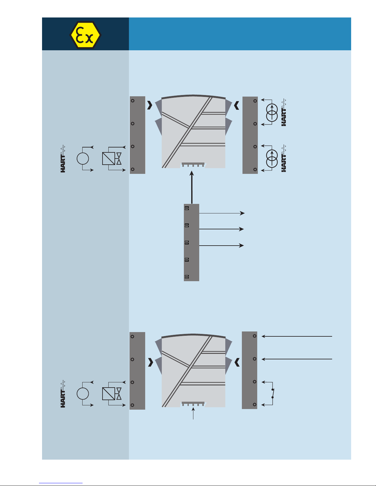
Applications
Input signals:
Analog, 4...20 mA
Output signals:
Channel 1
Current 4...20 mA
I/P converter
Channel 2
Channel 1
Zone 0, 1, 2,
20, 21, 22, M1 &
Cl. I/II/III, Div. 1
gr. A-G
Zone 2 & Cl. 1, Div. 2, gr. A-D
or Safe Area
Device status
Device status
Supply -
Supply +19.2...31.2 VDC
N.C.
Power connection:
Same power rail as above
Rail, supply +
Power rail
Status relay signal
No connection
No connection
Channel 2
Current 4...20 mA
I/P converter
Rail, supply -
OK
4501
1
3
4
2
3
8 9107 - Product version 9107-002
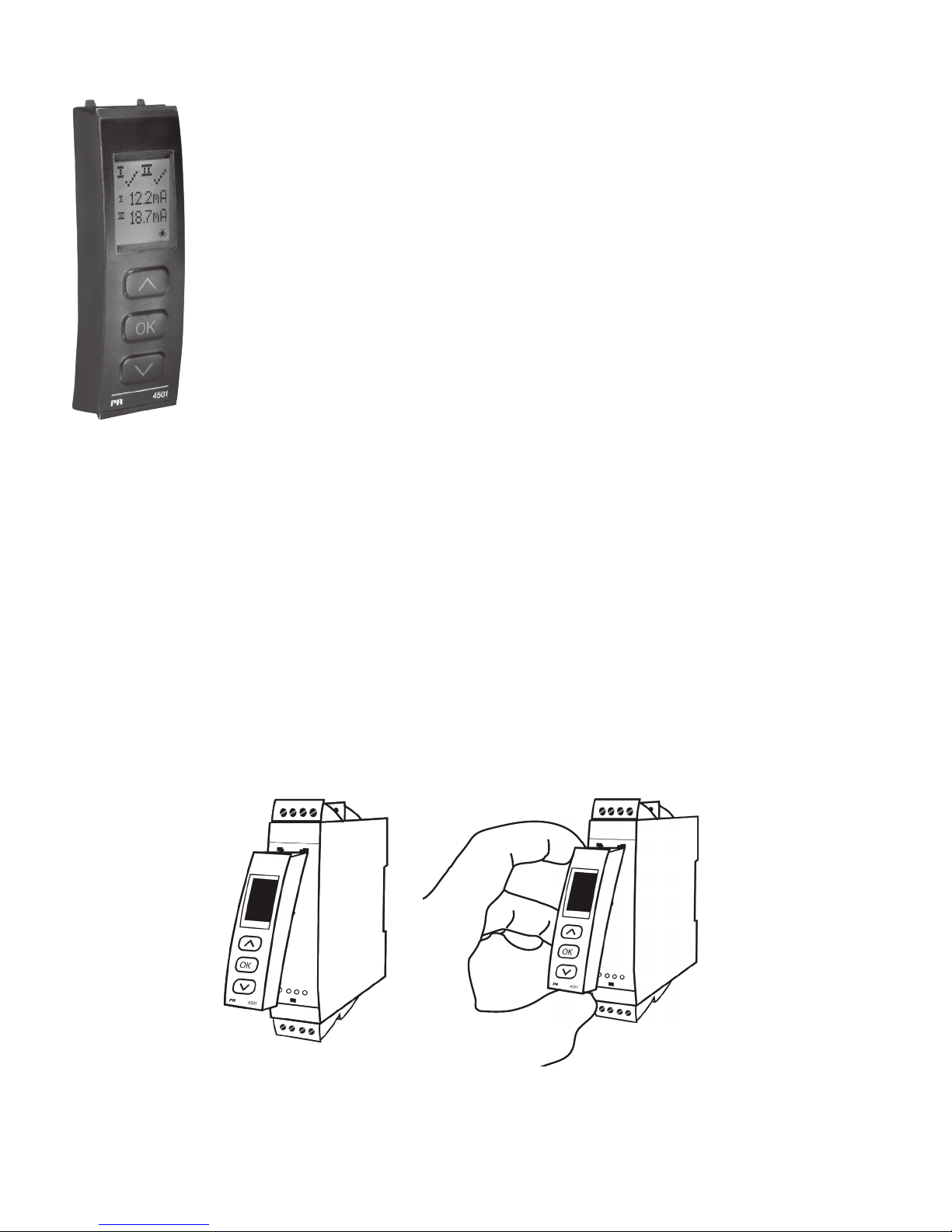
PR 4511/4501 display / programming front
Functionality
The simple and easily understandable menu structure and the explanatory help texts guide you
effortlessly and automatically through the configuration steps, thus making the product very easy to
use. Functions and configuration options are described in the section ”Configuration / operating the
function keys”.
Application
• Communications interface for modification of operational parameters in 9107B.
• When mounted in the process, the display shows process values and device status.
Technical characteristics
• LCD display with 4 lines:
Line 1 (H=5.57 mm) shows status for each channel (OK or error).
Line 2 (H=3.33 mm) shows loop current in mA for channel 1 or tag no.
Line 3 (H=3.33 mm) shows loop current in mA for channel 2 or tag no.
Line 4 shows communications status.
• In order to protect the configuration against unauthorised changes, access to the menus can be
blocked by a password.
Mounting / demounting the PR 4511/4501
1: Insert the tabs of the PR 4511/4501 into the holes at the top of the device.
2: Hinge the PR 4511/4501 down until it snaps into place.
Demounting of the PR 4511/4501
3: Push the release button on the bottom of the PR 4511/4501 and hinge the the PR 4511/4501 out and up.
4: With the PR 4511/4501 hinged up, remove from holes at the top of the device.

9107 - Product version 9107-002 9
Accessories
4501 = Display / programming front
4511 = Communication enabler
9400 = Power rail
9404 = Module stop for rail
9410 = Power control unit
9421 = Power supply 24 V - Ex nA nC
Technical data
Environmental conditions:
Specifications range. . . . . . . . . . . . . . . . . . . . . . . . . . . . . . . . . . -20°C to +60°C
Storage temperature . . . . . . . . . . . . . . . . . . . . . . . . . . . . . . . . . -20°C to +85°C
Calibration temperature. . . . . . . . . . . . . . . . . . . . . . . . . . . . . . . . 20...28°C
Relative humidity . . . . . . . . . . . . . . . . . . . . . . . . . . . . . . . . . . . < 95% RH (non-cond.)
Protection degree . . . . . . . . . . . . . . . . . . . . . . . . . . . . . . . . . . . IP20
Installation in . . . . . . . . . . . . . . . . . . . . . . . . . . . . . . . . . . . . . . Pollution degree 2 & overvoltage category II.
Mechanical specifications:
Dimensions (HxWxD) . . . . . . . . . . . . . . . . . . . . . . . . . . . . . . . . . 109 x 23.5 x 104 mm
Dimensions (HxWxD) w/ 4501/4511. . . . . . . . . . . . . . . . . . . . . . . . 109 x 23.5 x 116 / 131 mm
Weight approx. . . . . . . . . . . . . . . . . . . . . . . . . . . . . . . . . . . . . . 250 g
Weight incl. 4501/4511 (approx.). . . . . . . . . . . . . . . . . . . . . . . . . . 265 g / 280 g
DIN rail type. . . . . . . . . . . . . . . . . . . . . . . . . . . . . . . . . . . . . . . DIN EN 60715 - 35 mm
Wire size. . . . . . . . . . . . . . . . . . . . . . . . . . . . . . . . . . . . . . . . . 0.13...2.08 mm
2
/ AWG 26...14 stranded wire
Screw terminal torque. . . . . . . . . . . . . . . . . . . . . . . . . . . . . . . . . 0.5 Nm
Vibration. . . . . . . . . . . . . . . . . . . . . . . . . . . . . . . . . . . . . . . . . IEC 60068-2-6
2...13.2 Hz . . . . . . . . . . . . . . . . . . . . . . . . . . . . . . . . . . . . . . ±1 mm
13.2...100 Hz . . . . . . . . . . . . . . . . . . . . . . . . . . . . . . . . . . . . . ±0.7 g
Common electrical specifications:
Supply voltage . . . . . . . . . . . . . . . . . . . . . . . . . . . . . . . . . . . . . 19.2...31.2 VDC
Fuse . . . . . . . . . . . . . . . . . . . . . . . . . . . . . . . . . . . . . . . . . . . 1.25 A SB / 250 VAC
Max. required power is the maximum power needed at terminals 31 and 32.
Max. power dissipation is the maximum power dissipated by the device.
If the 9107 is used with the 4511/4501, then add 40 mW to the max. power dissipation and 70 mW to the max. required power for each
device with the 4511/4501.
Isolation - test / working:
Input to any. . . . . . . . . . . . . . . . . . . . . . . . . . . . . . . . . . . . . . 2.6 kVAC / 300 VAC reinforced isolation
Analog output to supply . . . . . . . . . . . . . . . . . . . . . . . . . . . . . . 2.6 kVAC / 300 VAC reinforced isolation
Status relay to supply. . . . . . . . . . . . . . . . . . . . . . . . . . . . . . . . 1.5 kVAC / 150 VAC reinforced isolation
Order
Example : 9107BB
Type Unit channels
9107B Single
Double
: A
: B
Typ e Description
Max. power
dissipation
Max. required
power
9107BA 1 channel ≤ 1.0 W ≤ 1.0 W
9107BB 2 channels ≤ 1.8 W ≤ 1.8 W
 Loading...