

Page 1
PERFORMANCE
MADE
SMARTER
Product Manual
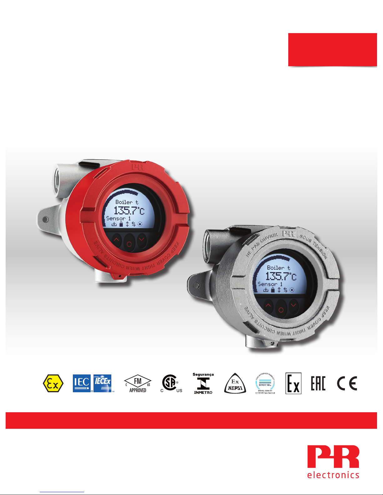
7501
Field mounted HART
temperature transmitter
TEMPERATURE | I.S. INTERFACES | COMMUNICATION INTERFACES | MULTIFUNCTIONAL | ISOLATION | DISPLAY
No. 7501V107-UK
Serial no.: 170807001-170816075
Page 2
6 Product Pillars
to meet your every need
With our innovative, patented technologies, we make signal conditioning smarter and simpler. Our portfolio is composed of six
product areas, where we offer a wide range of analog and digital devices covering over a thousand applications in industrial
and factory automation. All our products comply with or surpass the highest industry standards, ensuring reliability in even
the harshest of environments and have a 5-year warranty for greater peace of mind.
Individually outstanding, unrivalled in combination
Our range of temperature transmitters and sensors provides the highest level of signal integrity from the
measurement point to your control system. You can convert industrial process temperature signals to analog, bus or
digital communications using a highly reliable point-to-point solution with a fast response time, automatic selfcalibration, sensor error detection, low drift, and top EMC performance in any environment.
Our unique range of single devices covering multiple applications is easily deployable as your site standard. Having
one variant that applies to a broad range of applications can reduce your installation time and training, and greatly
simplify spare parts management at your facilities. Our devices are designed for long-term signal accuracy, low
power consumption, immunity to electrical noise and simple programming.
We provide inexpensive, easy-to-use, future-ready communication interfaces that can access your PR installed base
of products. The detachable 4501 Local Operator Interface (LOI) allows for local monitoring of process values,
device configuration, error detection and signal simulation. The next generation, our 4511 Remote Operator
Interface (ROI) does all that and more, adding remote digital communications via Modbus/RTU, while the analog
output signals are still available for redundancy.
With the 4511 you can further expand connectivity with a PR gateway, which connects via industrial Ethernet,
wirelessly through a Wi-Fi router or directly with the devices using our Portable Plant Supervisor (PPS) application.
The PPS app is available for iOS, Android and Windows.
Our display range is characterized by its flexibility and stability. The devices meet nearly every demand for display
readout of process signals, and have universal input and power supply capabilities. They provide a real-time
measurement of your process value no matter the industry, and are engineered to provide a user-friendly and
reliable relay of information, even in demanding environments.
We deliver the safest signals by validating our products against the toughest safety standards. Through our
commitment to innovation, we have made pioneering achievements in developing I.S. interfaces with SIL 2 Full
Assessment that are both efficient and cost-effective. Our comprehensive range of analog and digital intrinsically
safe isolation barriers offers multifunctional inputs and outputs, making PR an easy-to-implement site standard.
Our backplanes further simplify large installations and provide seamless integration to standard DCS systems.
Our compact, fast, high-quality 6 mm isolators are based on microprocessor technology to provide exceptional
performance and EMC-immunity for dedicated applications at a very low total cost of ownership. They can be
stacked both vertically and horizontally with no air gap separation between units required.
Page 3

7501V107-UK 3
Field mounted HART
temperature transmitter
7501
Table of contents
Warning ................................................................................................ 4
Applications ............................................................................................ 5
Order................................................................................................... 6
Accessories ............................................................................................. 6
Technical data .......................................................................................... 6
Block diagram .......................................................................................... 9
Marking................................................................................................. 9
Mechanical specifications ................................................................................ 10
Mounting ............................................................................................... 12
Protection degree . . . . . . . . . . . . . . . . . . . . . . . . . . . . . . . . . . . . . . . . . . . . . . . . . . . . . . . . . . . . . . . . . . . . . . . . . . . . . . . . . . . . . . . 14
Assembly and disassembly .............................................................................. 15
Connections ............................................................................................ 20
Optical buttons.......................................................................................... 21
Operating the optical buttons ............................................................................ 21
Display ................................................................................................. 21
Device and sensor status indication ...................................................................... 24
Display menu ........................................................................................... 25
Display .............................................................................................. 28
Tags................................................................................................. 28
Calibration ........................................................................................... 29
Simulation ........................................................................................... 30
Sensor .............................................................................................. 31
HART................................................................................................ 31
Write-protect ........................................................................................ 32
Language............................................................................................ 32
HART Revision ....................................................................................... 32
Help text overview ...................................................................................... 33
Programming ........................................................................................... 37
Changing the HART protocol version ...................................................................... 38
Retrofit................................................................................................. 40
Appendix . . . . . . . . . . . . . . . . . . . . . . . . . . . . . . . . . . . . . . . . . . . . . . . . . . . . . . . . . . . . . . . . . . . . . . . . . . . . . . . . . . . . . . . . . . . . . . . 41
ATEX Installation Drawing ............................................................................ 42
IECEx Installation Drawing ............................................................................ 48
FM Installation Drawing............................................................................... 54
CSA Installation Drawing.............................................................................. 59
Desenho de instalaçao INMETRO ...................................................................... 62
Document history ....................................................................................... 68
Page 4

4 7501V107-UK
Warning
Only technicians, who are familiar with the technical terms, warnings, and instructions in the manual and
who are able to follow these, should connect the device.
Should there be any doubt as to the correct handling of the device, please contact your local distributor
or PR electronics A/S.
Mounting and connection of the device should comply with national legislation for mounting of electric
materials.
Repair of the device must be done by PR electronics A/S only.
Do not remove the transmitter cover in explosive atmospheres when the circuit is live.
The transmitter cover must be fully engaged to meet the explosion proof requirements.
If installed under high-vibration conditions, the transmitter may require supplementary support.
For installation in hazardous area the corresponding installation drawing must be followed in detail.
Take care not to generate mechanical sparking when accessing the instrument and peripheral devices in
a hazardous location.
Page 5

+
-
+
-
+
-
+-
+-
21
2
21
1
1
2
+
-
7501V107-UK 5
Field mounted HART temperature transmitter
7501
• RTD, TC, Ohm, and bipolar mV input and analog output
• High definition local operator interface (LOI) with 3 optical buttons
• Selectable red or white backlight
• Ex d explosion proof / flameproof in aluminum or 316 stainless steel version
• HART 7 functionality with HART 5 compatibility
High defintion display
• 0, 90, 180, & 270 degree position adjustments.
• Monitoring, programming and diagnostics view.
• Extensive diagnostics with flashing red or white backlight
• Supports 7 languages.
Local operator interface (LOI)
• 3 optical buttons; up, down and enter.
• Dynamically adaptive to wear or accumulation of dirt.
• Immune to interference from ambient light sources.
• Useable with or without gloves.
Configuration
• From the LOI through the PR guided menu.
• PReset and HART modem.
• HHC, DCS or AMS via HART.
Mounting / installation
• For installation in zone 0, 1, 2 and zone 20, 21, 22,and in
Class 1, Division 1 and 2 applications.
• Hardware assessed for use in SIL 2 applications.
• Mounting on 1.5”–2” pipe bracket or on wall / bulkhead.
Application
• Linearized temperature measurement with TC and RTD
sensors e.g. Pt100 and Ni100.
• HART communication and 4...20 mA analog PV output for
individual, difference or average temperature
measurement of up to two RTD or TC input sensors.
• Conversion of linear resistance to a standard analog
current signal, e.g from valves or Ohmic level sensors.
• Amplification of bipolar mV signals to standard 4...20 mA
current signals.
• Up to 63 transmitters (HART 7) can be connected in a
multidrop communication setup.
Technical characteristics
• NAMUR NE43 and NE89.
• HART protocol revision can be changed by user
configuration to either HART 5 or HART 7 protocol.
Applications
Input signals:
TC to 4...20 mA
Ex ia: 10...30 VDC
(12...30 VDC with backlight)
Other: 10...35 VDC
(12...35 VDC with backlight)
4...20 mA
Resistance to 4...20 mA
mV to 4...20 mA
Difference or average
RTD, TC or mV
2-wire output and HART:
RTD to 4...20 mA
Page 6

6 7501V107-UK
Accessories
8550 = 7501 M20 plug text alu encl. silicone O-ring
8550-F = 7501 M20 plug text alu encl. FKM O-ring
8550-S = 7501 M20 plug text stainless steel encl. silicone O-ring
8550-SF = 7501 M20 plug text stainless steel encl. FKM O-ring
8551 = 7501 NPT plug alu encl.
8551-S = 7501 NPT plug text stainless steel encl.
8552 = Pipe-mounting bracket P5-B-N (1½”-2”)
1117 = 5-point calibration certificate
Technical data
Environmental conditions:
Operating tempeature
with silicone O-ring . . . . . . . . . . . . . . . . . . . . . . . . . . . . . . . . . -40°C to +85°C
with FKM O-ring . . . . . . . . . . . . . . . . . . . . . . . . . . . . . . . . . . . -20°C to +85°C
Reduced LCD performance below -20°C and above +70°C
Storage temperature . . . . . . . . . . . . . . . . . . . . . . . . . . . . . . . . . -40°C to +85°C
Calibration temperature. . . . . . . . . . . . . . . . . . . . . . . . . . . . . . . . 20...28°C
Relative humidity . . . . . . . . . . . . . . . . . . . . . . . . . . . . . . . . . . . 0...100% RH (condensing)
Protection degree . . . . . . . . . . . . . . . . . . . . . . . . . . . . . . . . . . . IP54 / IP66 / IP68 / type 4X
Mechanical specifications:
Dimensions . . . . . . . . . . . . . . . . . . . . . . . . . . . . . . . . . . . . . . . Ø 110 mm
Dimensions, H x W x D, aluminum / stainless steel. . . . . . . . . . . . . . . . 109.3 x 145 x 126 mm / 107.4 x 145 x 124
Weight approx., aluminum / stainless steel . . . . . . . . . . . . . . . . . . . . 1.3 / 2.8 kg
Wire size. . . . . . . . . . . . . . . . . . . . . . . . . . . . . . . . . . . . . . . . . 0.13...1.5 mm
2
/ AWG 26...16 stranded wire
Screw terminal torque. . . . . . . . . . . . . . . . . . . . . . . . . . . . . . . . . 0.4 Nm
Vibration. . . . . . . . . . . . . . . . . . . . . . . . . . . . . . . . . . . . . . . . . IEC 60068-2-6
2...25 Hz. . . . . . . . . . . . . . . . . . . . . . . . . . . . . . . . . . . . . . . . ±1.6 mm
25...100 Hz . . . . . . . . . . . . . . . . . . . . . . . . . . . . . . . . . . . . . . ±4 g
Display:
Display resolution . . . . . . . . . . . . . . . . . . . . . . . . . . . . . . . . . . . 96 x 64 pixels
Number of digits . . . . . . . . . . . . . . . . . . . . . . . . . . . . . . . . . . . . 5
Response time, button to display . . . . . . . . . . . . . . . . . . . . . . . . . . < 150 ms
Backlight . . . . . . . . . . . . . . . . . . . . . . . . . . . . . . . . . . . . . . . . Selectable ON / OFF
Backlight color . . . . . . . . . . . . . . . . . . . . . . . . . . . . . . . . . . . . . Selectable white or red
Error indication . . . . . . . . . . . . . . . . . . . . . . . . . . . . . . . . . . . . . Selectable white or red (flashing)
Common electrical specifications:
Supply voltage, DC:
Ex ia, intrinsically safe . . . . . . . . . . . . . . . . . . . . . . . . . . . . . . . 10...30 VDC
(12...30 VDC with backlight)
Other. . . . . . . . . . . . . . . . . . . . . . . . . . . . . . . . . . . . . . . . . . 10...35 VDC
(12...35 VDC with backlight)
Order
Example : 7501A3B1A12
Type Housing
Local operator
interface
O-ring
Conduit
thread
(D1, D2 & D3)
Paint
type
Transmitter Approvals
Cover color
Optical
buttons
Display
7501 Low copper
aluminum (AL)
: A No
No
Yes
No
Yes
Yes
: 1
: 2
: 3
-40 to +85°C
silicone rubber
-20 to +85°C
FKM rubber
: A
: B
M20x1.5 6H
½ NPT mod.
: 1
: 2
Epoxy
Epoxy + polyurethane
: A
: B
Yes
No
(comes with
a connection kit)
: 1
: 2
General
purpose
Hazardous
area
: 1
: 2
Red
Grey
: -
: GY
7501 316 Stainless
steel (RF)
: B No
Yes
Yes
Yes
: 2
: 3
-40 to +85°C
silicone rubber
-20 to +85°C
FKM rubber
: A
: B
M20x1.5 6H
½ NPT mod.
: 1
: 2
None : N Yes
No
(comes with
a connection kit)
: 1
: 2
General
purpose
Hazardous
area
: 1
: 2
Steel : -
Page 7
7501V107-UK 7
Isolation - test / working . . . . . . . . . . . . . . . . . . . . . . . . . . . . . . . 1.5 kVAC / 50 VAC
Signal / noise ratio. . . . . . . . . . . . . . . . . . . . . . . . . . . . . . . . . . . > 60 dB
Programming . . . . . . . . . . . . . . . . . . . . . . . . . . . . . . . . . . . . . . HART
Start-up time (transmitter to display). . . . . . . . . . . . . . . . . . . . . . . . Max. 5 s
Response time (programmable) . . . . . . . . . . . . . . . . . . . . . . . . . . . 1...60 s
Long term stability. . . . . . . . . . . . . . . . . . . . . . . . . . . . . . . . . . . 0.1% of span / year
Accuracy, the greater of general and basic values:
TC B
1
accuracy specification range . . . . . . . . . . . . . . . . . . . . . . . . . > 400°C
TC B
2
accuracy specification range . . . . . . . . . . . . . . . . . . . . . . . . . > 160°C < 400°C
TC B3 accuracy specification range . . . . . . . . . . . . . . . . . . . . . . . . . > 85°C < 160°C
TC B
4
accuracy specification range . . . . . . . . . . . . . . . . . . . . . . . . . < 85°C
TC cold junction compensation. . . . . . . . . . . . . . . . . . . . . . . . . . . . < ±1.0°C
Max. oset on input signal . . . . . . . . . . . . . . . . . . . . . . . . . . . . . . 50% of selec. max. value
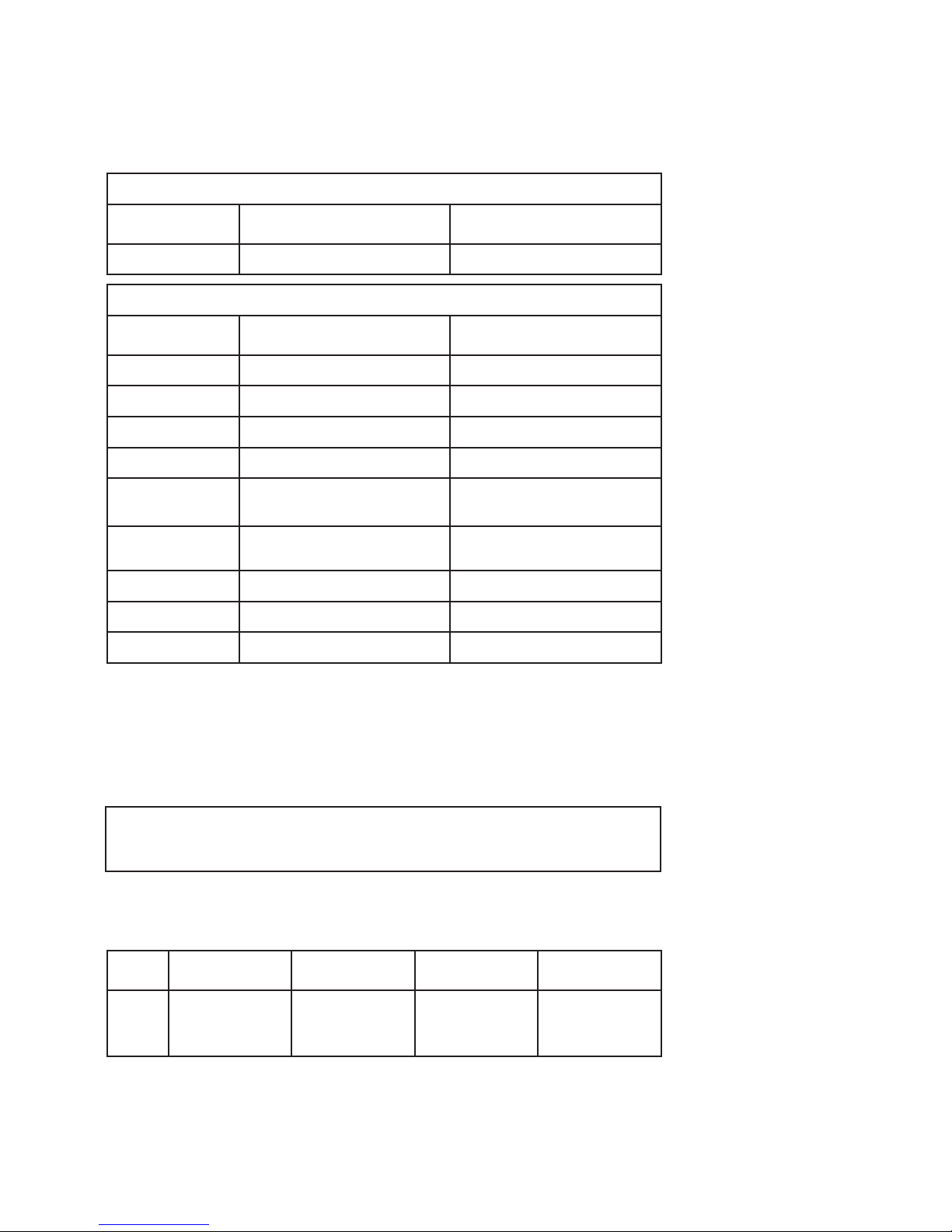
Input specifications:
RTD input types:
Pt50, Pt100, Pt200, Pt500, Pt1000, Ni50, Ni100, Ni120, Ni1000
Cable resistance per wire (max.). . . . . . . . . . . . . . . . . . . . . . . . . . . 5 Ω
(up to 50 Ω per wire is possible with reduced measurement accuracy)
Sensor current . . . . . . . . . . . . . . . . . . . . . . . . . . . . . . . . . . . . . Nom. 0.2 mA
RTD
type
Min.
value
Max.
value
Min.
span
Standard
Pt100
Ni100
Lin. R
-200°C
-60°C
0 Ω
+850°C
+250°C
7000 Ω
10°C
10°C
25 Ω
IEC 60751
DIN 43760
-----
EMC - immunity influence. . . . . . . . . . . . . . . . . . . . . . . . . < ±0.1% of span
Extended EMC immunity:
NAMUR NE 21, A criterion, burst . . . . . . . . . . . . . . . . . . . . < ±1% of span
General values
Input type Absolute accuracy Temperature coecient
All ≤ ±0.05% of span ≤ ±0.005% of span / °C
Basic values
Input type Basic accuracy Temperature coecient
Pt50 - Pt1000 ≤ ±0.1°C ≤ ±0.005°C/°C
Ni50 - Ni1000 ≤ ±0.2°C ≤ ±0.005°C/°C
Lin. R ≤ ±0.1 Ω ≤ ±5 mΩ / °C
Volt ≤ ±10 μV ≤ ±0.5 µV / °C
TC type:
E, J, K, L, N, T, U
≤ ±0.5°C
≤ ±0.025°C / °C
TC type:
B
1
, Lr, R, S, W3, W5
≤ ±1°C
≤ ±0.1°C / °C
TC type:B
2
≤ ±3°C ≤ ±0.3°C / °C
TC type:B
3
≤ ±8°C ≤ ±0.8°C / °C
TC type:B
4
not specified not specified
Page 8

8 7501V107-UK
TC input types:
Cold junction compensation (CJC):
Constant, internal or external via a Pt100 or Ni100 sensor
mV input:
Voltage input range . . . . . . . . . . . . . . . . . . . . . . . . . . . . . . . . . . -800...+800 mV
Min. span . . . . . . . . . . . . . . . . . . . . . . . . . . . . . . . . . . . . . . . . 2.5 mV
Input resistance . . . . . . . . . . . . . . . . . . . . . . . . . . . . . . . . . . . . 10 MΩ
Output specifications:
Signal range. . . . . . . . . . . . . . . . . . . . . . . . . . . . . . . . . . . . . . . 4...20 mA
Min. signal range . . . . . . . . . . . . . . . . . . . . . . . . . . . . . . . . . . . . 16 mA
Updating time . . . . . . . . . . . . . . . . . . . . . . . . . . . . . . . . . . . . . 440 ms
Load resistance. . . . . . . . . . . . . . . . . . . . . . . . . . . . . . . . . . . . . ≤ (Vsupply - 10) / 0.023 [Ω]
with backlight . . . . . . . . . . . . . . . . . . . . . . . . . . . . . . . . . . . . ≤ (Vsupply - 12) / 0.023 [Ω]
Sensor error detection, programmable . . . . . . . . . . . . . . . . . . . . . . . 3.5...23 mA
(shorted sensor error detection is ignored at TC and mV input)
NAMUR NE43 Upscale . . . . . . . . . . . . . . . . . . . . . . . . . . . . . . . . 23 mA
NAMUR NE43 Downscale. . . . . . . . . . . . . . . . . . . . . . . . . . . . . . . 3.5 mA
HART protocol revisions. . . . . . . . . . . . . . . . . . . . . . . . . . . . . . . . HART 7 and HART 5
Marine approval:
EU RO Mutual Recognition Type Approval . . . . . . . . . . . . . . . . . . . . . MRA0000009
Ex approvals:
ATEX 2014/34/EU . . . . . . . . . . . . . . . . . . . . . . . . . . . . . . . . . . . DEKRA 15 ATEX 0058 X
IECEx . . . . . . . . . . . . . . . . . . . . . . . . . . . . . . . . . . . . . . . . . . . IECEx DEK 15.0039 X
cFMus . . . . . . . . . . . . . . . . . . . . . . . . . . . . . . . . . . . . . . . . . . FM16US0009X / FM16CA0010X
cCSAus. . . . . . . . . . . . . . . . . . . . . . . . . . . . . . . . . . . . . . . . . . 70024231
INMETRO . . . . . . . . . . . . . . . . . . . . . . . . . . . . . . . . . . . . . . . . DEKRA 15.0014 X
NEPSI . . . . . . . . . . . . . . . . . . . . . . . . . . . . . . . . . . . . . . . . . . GYJ15.1336X, GYJ15.1337X and
GYJ15.1338X
EAC Ex TR-CU 012/2011 . . . . . . . . . . . . . . . . . . . . . . . . . . . . . . . RU C-DK.GB08.V.01316
Observed authority requirements:
EMC. . . . . . . . . . . . . . . . . . . . . . . . . . . . . . . . . . . . . . . . . . . . 2014/30/EU
RoHS . . . . . . . . . . . . . . . . . . . . . . . . . . . . . . . . . . . . . . . . . . . 2011/65/EU
EAC . . . . . . . . . . . . . . . . . . . . . . . . . . . . . . . . . . . . . . . . . . . . TR-CU 020/2011
Functional Safety:
Hardware assessed for use in SIL 2 applications
FMEDA report - www.prelectronics.com
Type
Min.
temperature
Max.
temperature
Min.
span
Standard
B
E
J
K
L
Lr
N
R
S
T
U
W3
W5
0°C
-100°C
-100°C
-180°C
-200°C
-200°C
-180°C
-50°C
-50°C
-200°C
-200°C
0°C
0°C
+1820°C
+1000°C
+1200°C
+1372°C
+900°C
+800°C
+1300°C
+1760°C
+1760°C
+400°C
+600°C
+2300°C
+2300°C
100°C
50°C
50°C
50°C
50°C
50°C
50°C
100°C
100°C
50°C
50°C
100°C
100°C
IEC584
IEC584
IEC584
IEC584
DIN 43710
GOST 3044-84
IEC584
IEC584
IEC584
IEC584
DIN 43710
ASTM E988-90
ASTM E988-90
Page 9
7501V107-UK 9
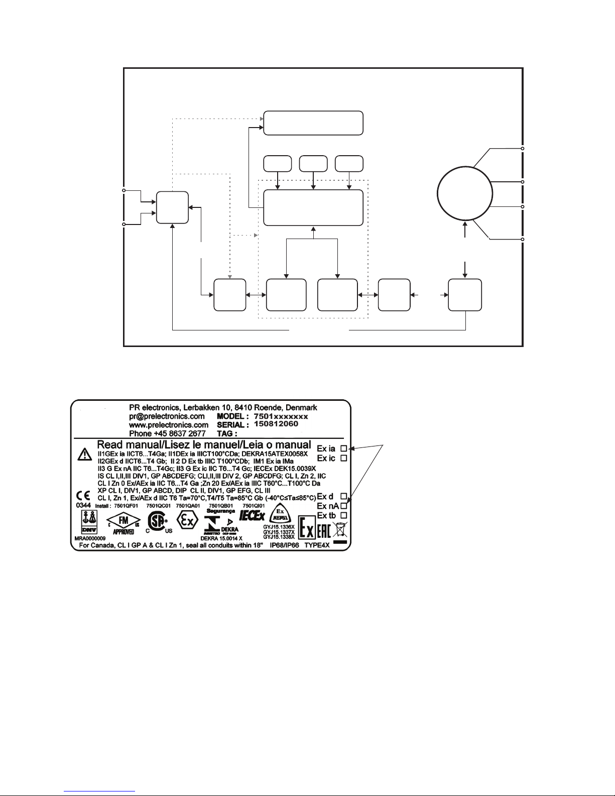
Block diagram
Marking
Caution
The ambient temperature range depends on T rating, type of protection and sealing materials, see the installation drawing.
T1
T2
T3
T4
T5
T6
7501
HART
HART
Application
Sensor
UP DOWN ENTER
HART
slave
HART
“master”
HART
modem
Filter
HART
modem
Supply
Display
5337
HART
transmitter
4...20 mA
+ HART
4...20 mA
+ HART
8 V / 4...20 mA
When this product has been installed as Ex
ia, ic, d, nA or tb, use a punch marker in the
appropriate box to indicate the type of
installation on the top label.
Page 10
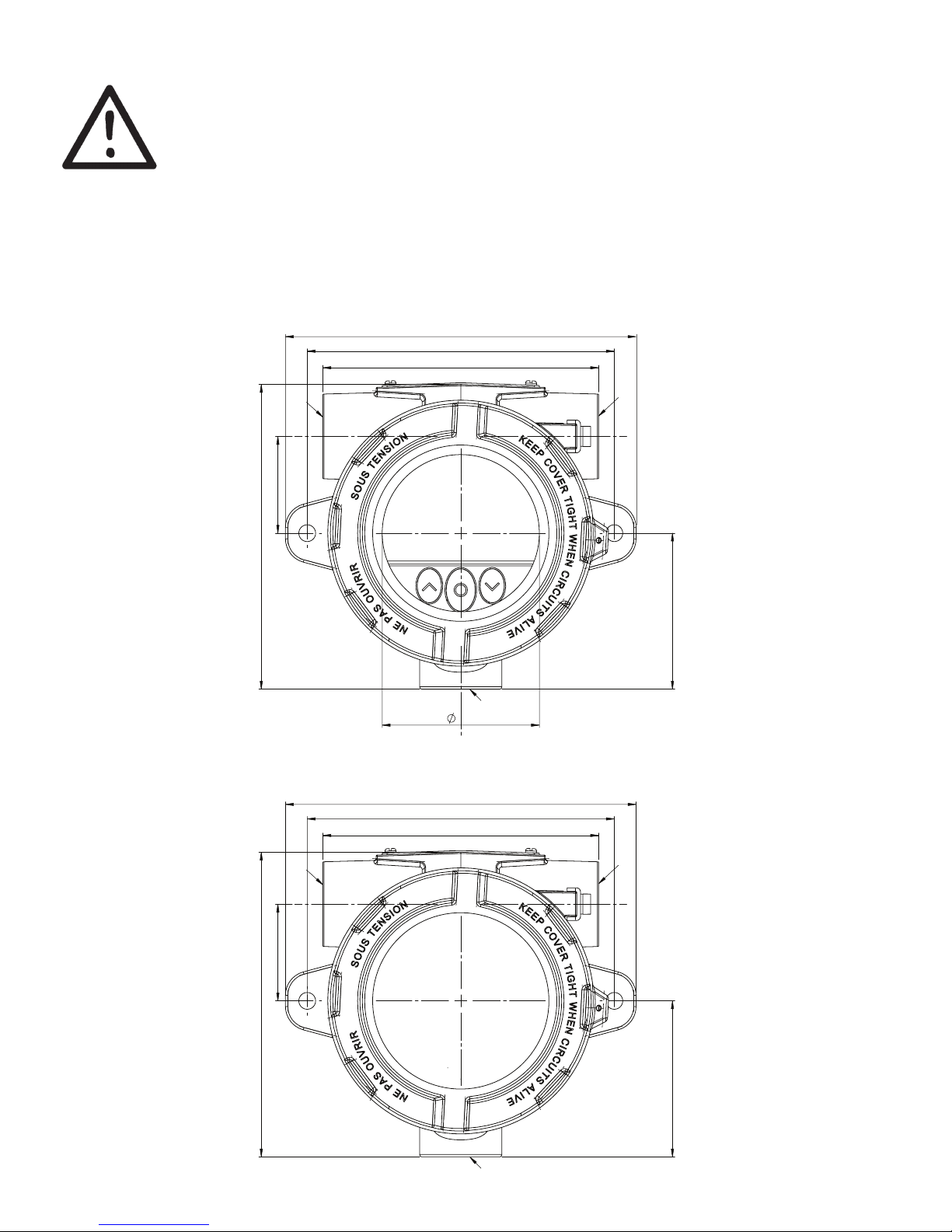
145
127
65
AL: 126
RF: 124
114
64,50
40
D1
D2
D3
145
127
114
64,50
40
D1
D2
D3
AL: 126
RF: 124
10 7501V107-UK
Mechanical specifications
It is important to be careful when screwing the cover on or off. The thread surface must be free of any
grains, pellets or other impurities as these can cause the cover to seize or damage the threads.
! Never use force to screw on the cover.
Should it be necessary to open the connection head cover after operation in maximum temperature,
please be aware that the cover may be blocked (does not give when attempting to open it by hand). In
this case, keep the cover under tension with your hand and hit the cover gently with a rubber hammer.
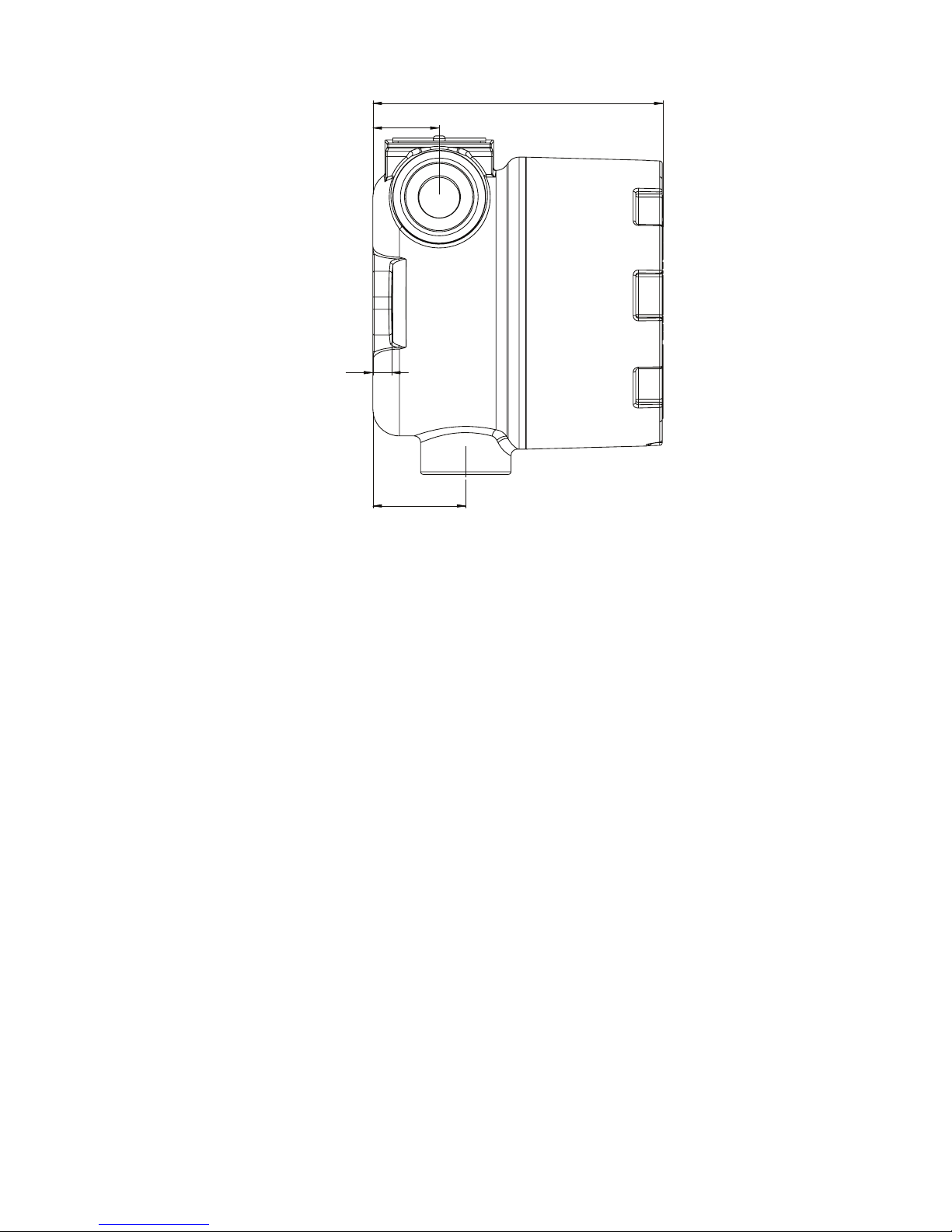
All dimensions below in mm. AL = aluminum version and RF = stainless steel version.
Front view – with buttons and display
Front view – no buttons or display
Page 11
AL: 7
RF: 6
AL: 109.3
RF: 107.4
AL: 35
RF: 34
AL: 25 / RF: 24
7501V107-UK 11
Side view
Page 12
2 x Ø 7
127
12 7501V107-UK
Mounting
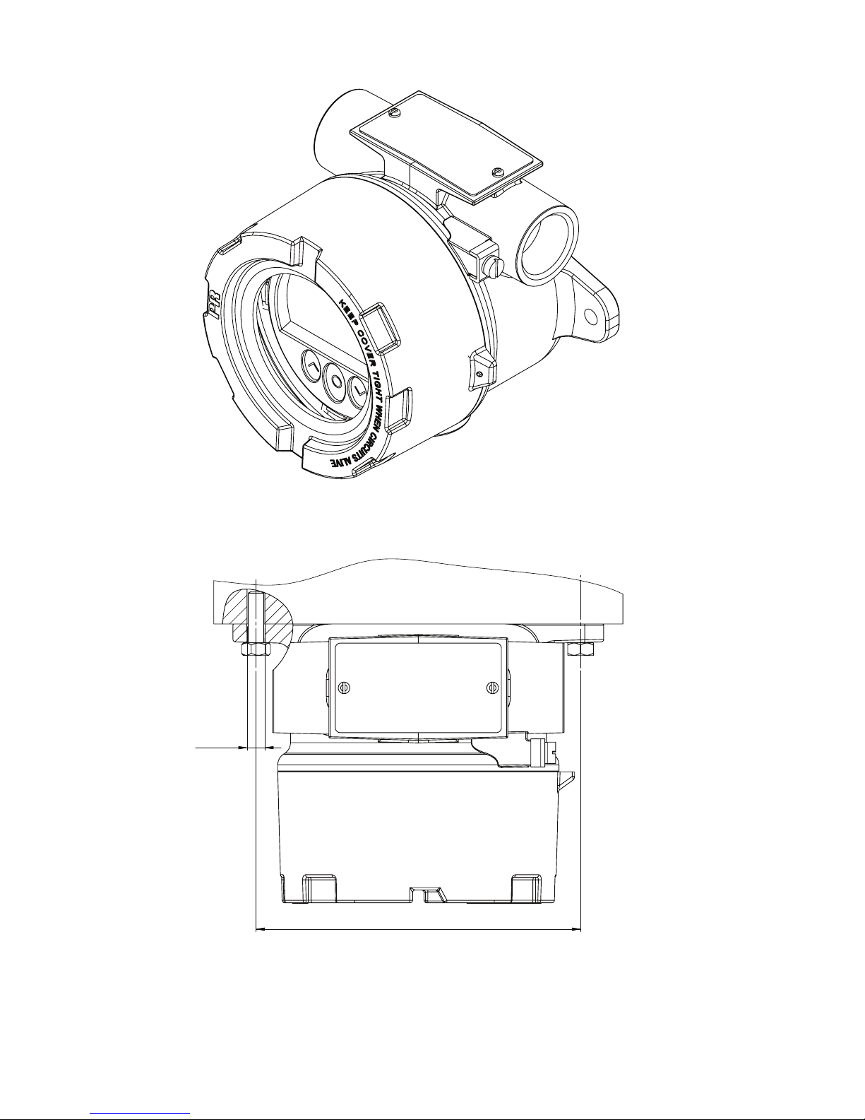
Wall-mounting – side view
Wall-mounting – top view
Page 13
M6
51
19
98
D = 1½" - 2"
7501V107-UK 13
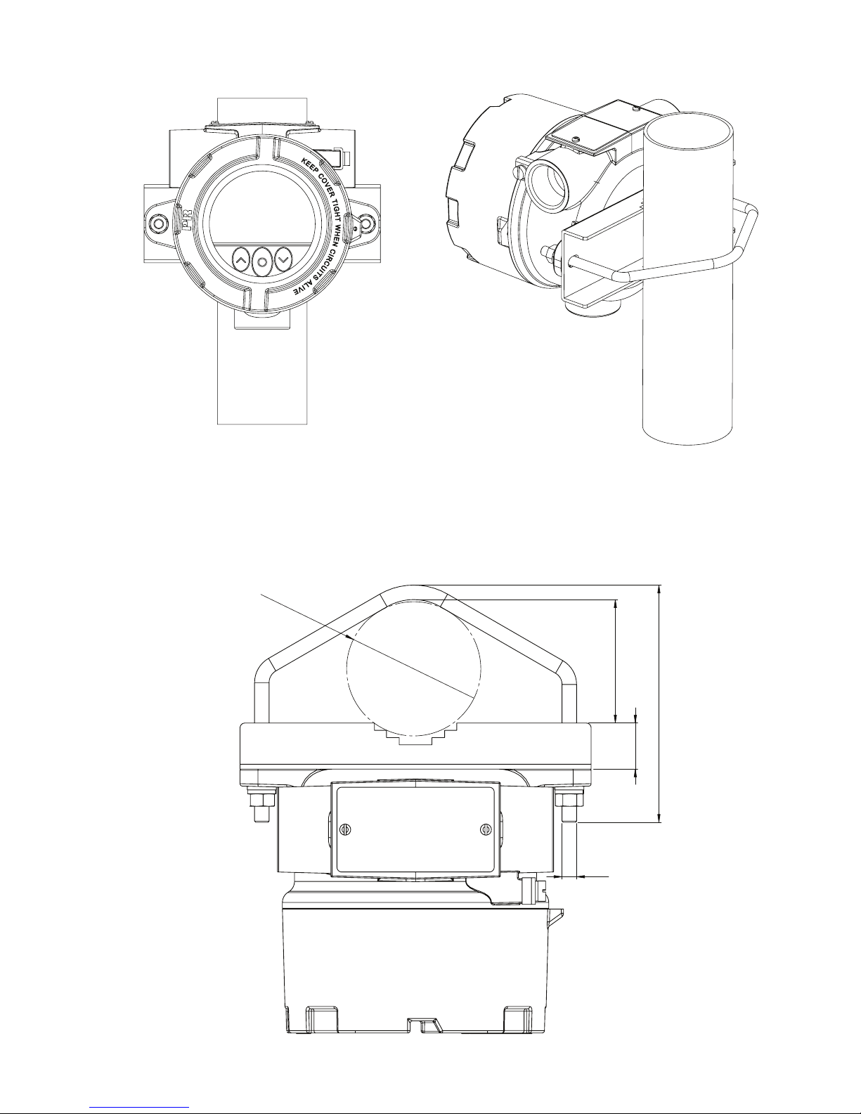
Pipe-mounting – front and back view
Pipe-mounting – top view
Page 14
14 7501V107-UK
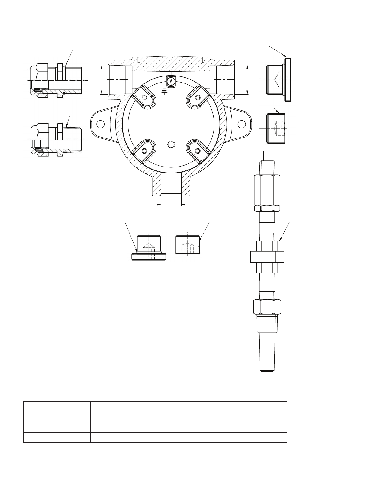
Protection degree
Blind plug M20 . . . . . . . . . . . . . . . . . . . . . . . . . . . . . . . . . . . . . IP54
With O-ring . . . . . . . . . . . . . . . . . . . . . . . . . . . . . . . . . . . . . . IP66 - IP68
Blind plug ½” NPT MOD . . . . . . . . . . . . . . . . . . . . . . . . . . . . . . . . IP54
With locktite 577 . . . . . . . . . . . . . . . . . . . . . . . . . . . . . . . . . . IP66 - IP68
Protection degree is defined by the connection with the lowest IP rating.
It is optional to connect a sensor to any of the three conduit openings.
Blind plugs are Ex approved only when used together with 7501.
Earth terminal and protection terminal
Placement Typ e
Cable cross section [mm
2
]
Stranded wire Solid wire
Inside Protection terminal 1.5 2.5
Outside Earth terminal 4.0 6.0
D1
D2
D3
Sealing washer
Threaded sealant
Sealing washer
Threaded sealant
Threaded sealant
SensorSealing washer
Blanking elements
Cable glands
20 x 1.5
½ NPTmod
½ NPTmod
20 x 1.5
Page 15
A-F = 2mm
1 2
3 3
7501V107-UK 15
Assembly and disassembly
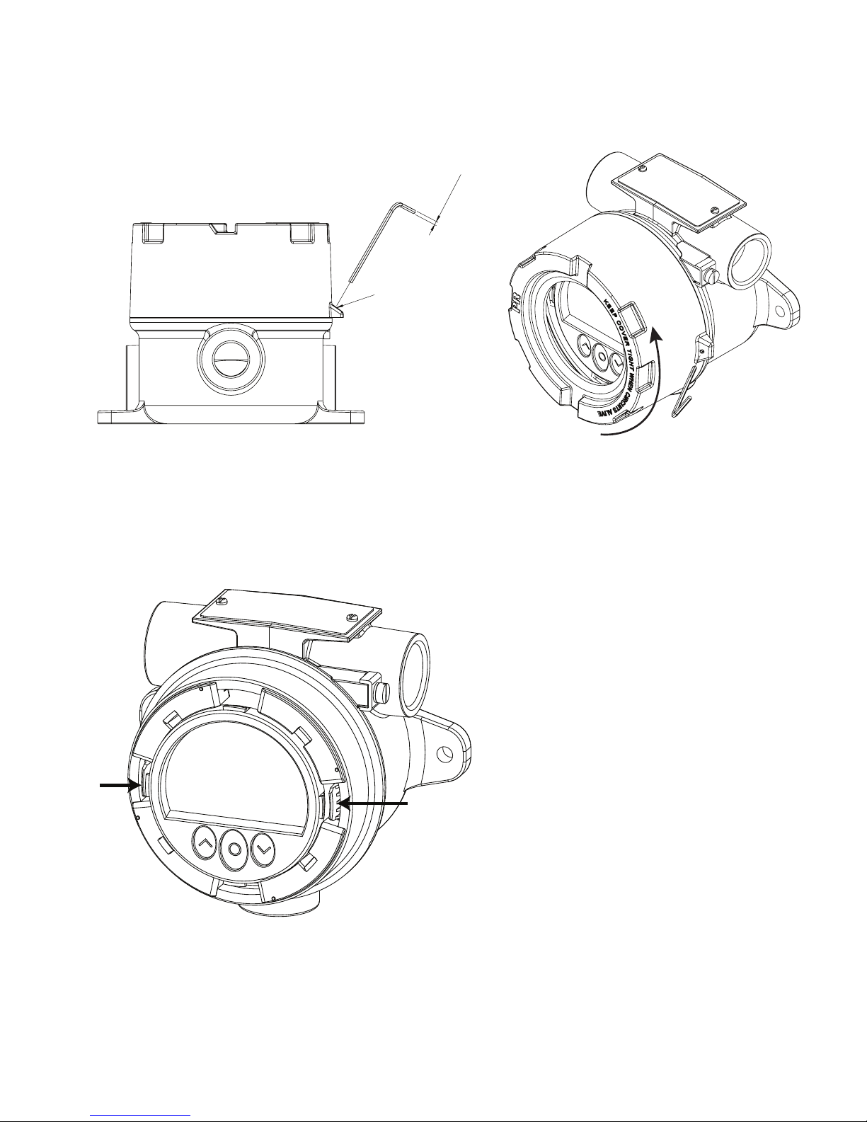
To connect sensor wires to the 7501 or change the orientation of the display, the housing must be disassembled and the
internal device must be extracted.
!! Disconnect power to the device before disassembly.
1. Release the locking screw, using a hex spanner with a cross-flat of 2 [mm]. This screw is situated on the housing top.
2. Unscrew the housing lid by turning it counterclockwise.
Point 3 and 4 only apply to devices with buttons and display.
3. Press and hold the two clamps located on the left and right side of the display unit.
Locking screw
Page 16
a a
b b
16 7501V107-UK
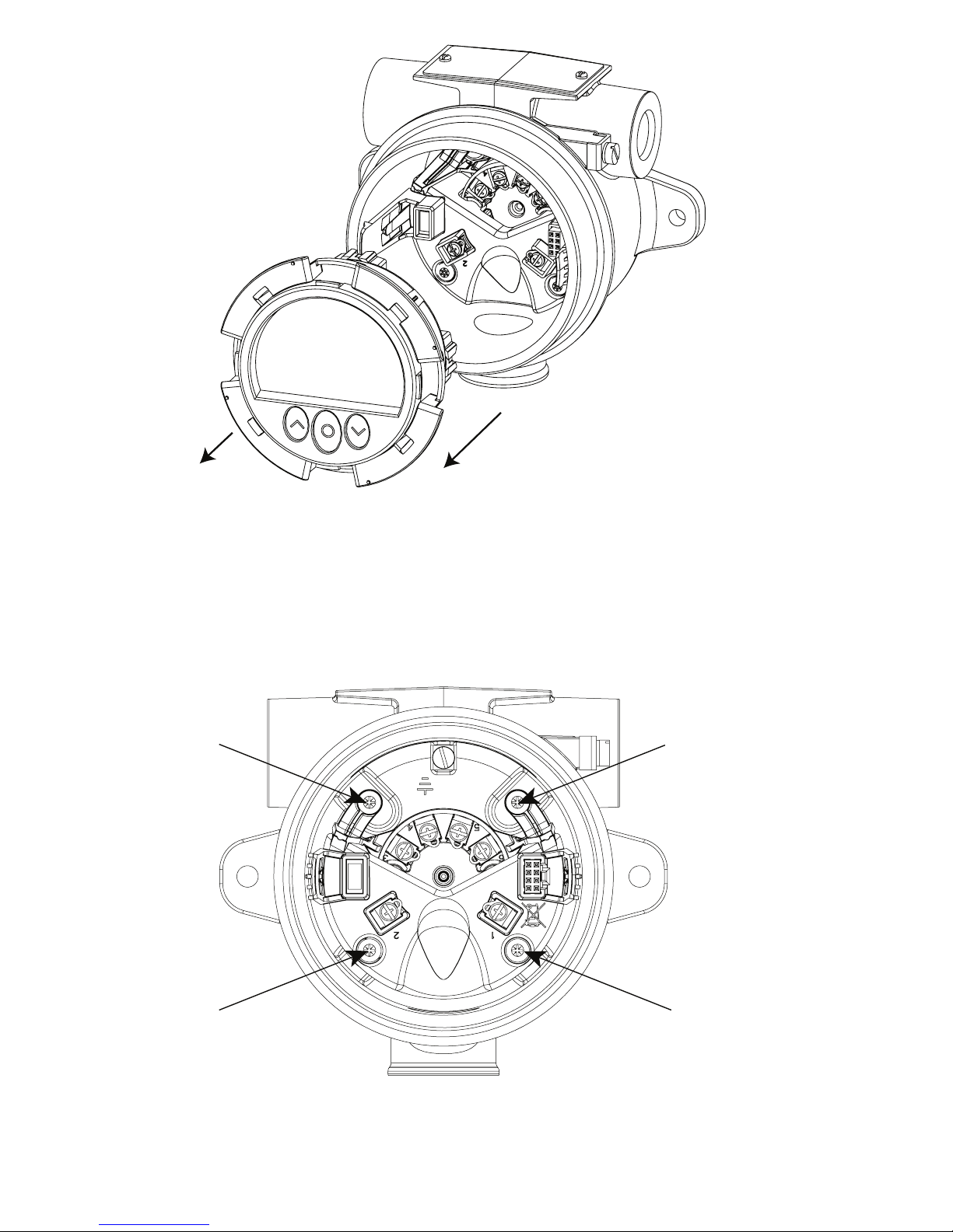
4. While holding the clamps, pull the display unit outwards to remove it.
5. The display can now be turned in steps of 90 degrees for best viewing angle.
6. For easy connection of sensor wires, we recommend extracting the transmitter from the housing (see the section
Connections for information on connecting sensors to the internal 5337).
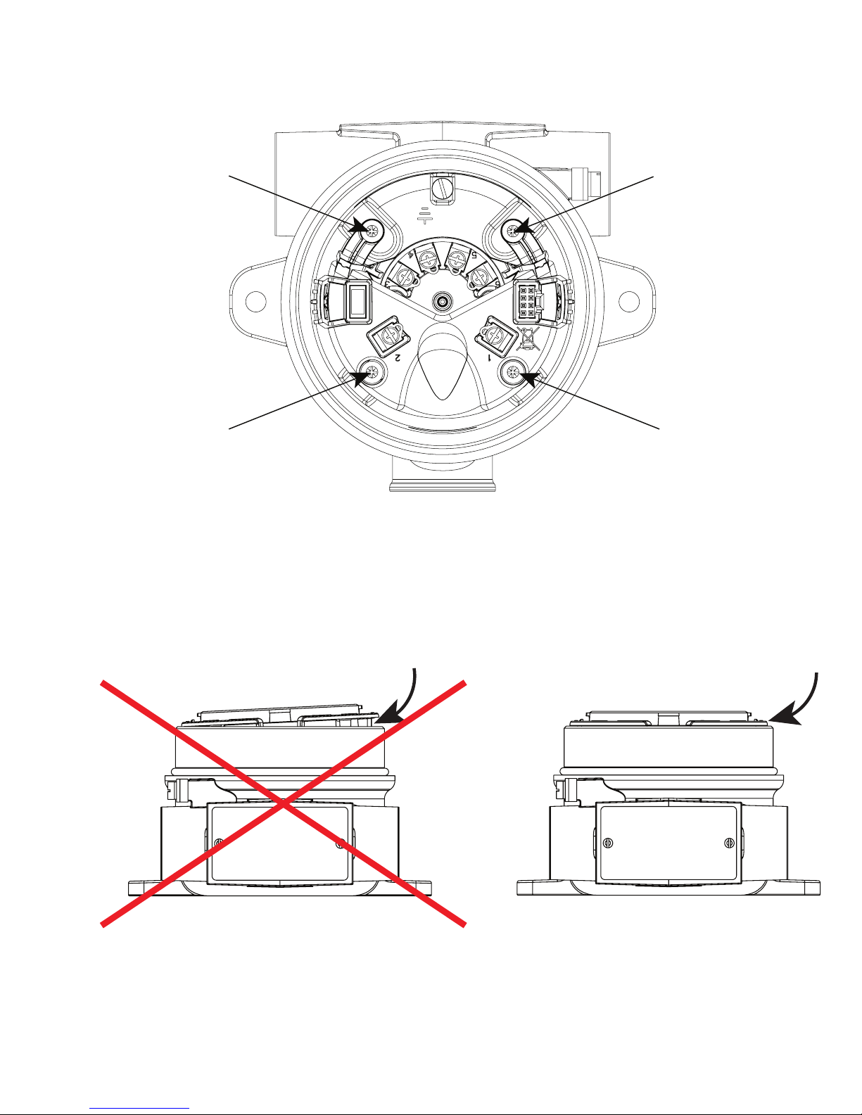
7. Unscrew the two screws (a) fastening the connector bracket to the housing, using a Posidriv form Z screwdriver.
8. Unscrew the two screws (b) fastening the fixation bracket to the housing, and pull out the entire assembly.
Page 17
7501V107-UK 17
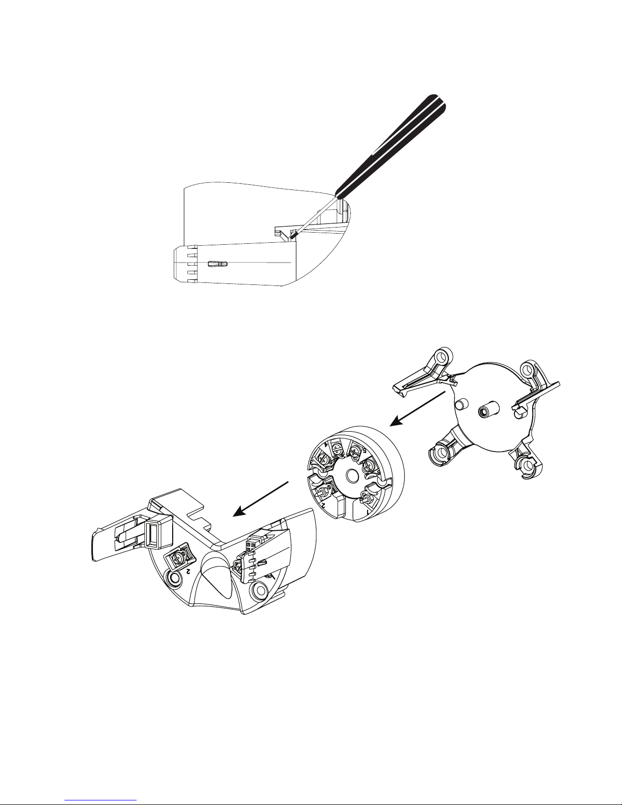
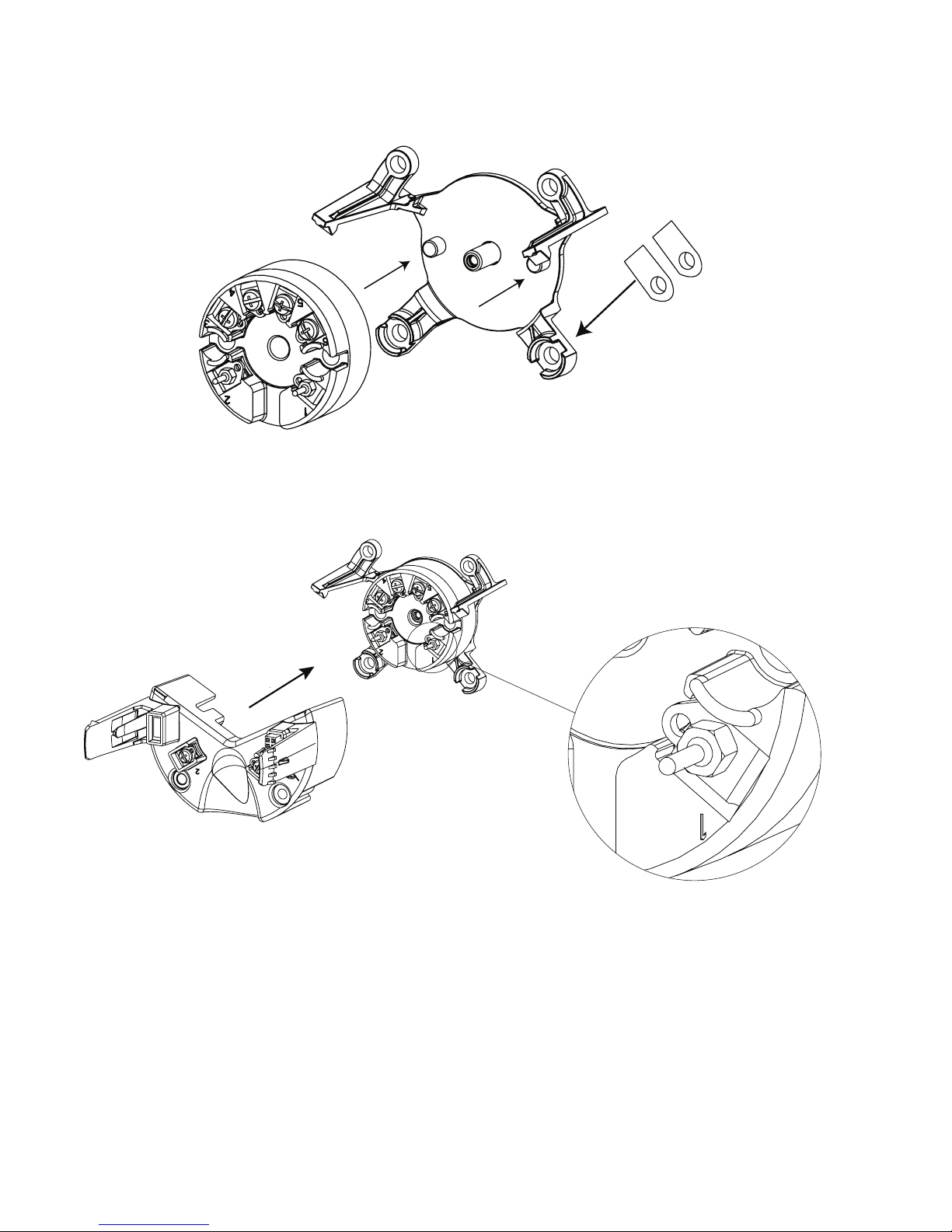
9. Use a screwdriver (or your fingers) to lever the taps (one on each side) on the fixation bracket to release it from the
transmitter connector bracket.
NB! Do not use excessive force.
10. Separate the connector bracket, transmitter and fixation bracket.
Page 18
RF
Al
18 7501V107-UK
Assembly
1. Place the transmitter in the fixation bracket using the guidance taps on the bracket. Make sure terminals 1 and 2 are
facing downwards.
NB. The fixation bracket is not interchangeable between the aluminum and stainless steel housing. Check the bottom
right-hand corner for identifier (Al for aluminum and RF for stainless steel).
2. Slide the connector bracket onto the transmitter using the dovetails as guides. Make sure the golden connector pins on
terminal 1 and 2 on the transmitter slide into place in the corresponding terminals on the connector bracket.
Press the bracket into place until you hear a distinct click.
Page 19
a a
b b
7501V107-UK 19
3. Slide the assembly back into the housing and refasten the 4 screws (a + b), using the 28 mm screws for the connector
bracket (a) and the 10 mm screws for the fixation bracket (b).
4. Finally, click the display unit back into place and screw the cover back on.
Correct mounting of display unit
Page 20

20 7501V107-UK
Connections
+
-
12
+
-
1
+
-
2
+-+
-
12
+
-
+
-
2 1
3
4
6
5
+
-
3
4
6
5
3
4
6
5
+
-
3
4
6
5
3
4
6
5
3
4
6
5
3
4
6
5
3
4
6
5
3
4
6
5
3
4
6
5
3
4
6
5
3
4
6
5
3
4
6
5
-
+
12
m
A
Output:
Input:
Resistance, 2-wire
Resistance, 3-wire
RTD, 2-wire RTD, 3-wire RTD, 4-wire
TC, internal CJC
TC, external CJC mV
Resistance, 4-wire
TC, dierence
or average,
with external CJC
mV, dierence
or average
RTD, dierence
or average
TC, dierence
or average,
with internal CJC
Page 21

7501V107-UK 21
Optical buttons
The user interface features 3 optical buttons: , 2 and . The buttons can be operated both with or without gloves1.
The buttons are immune to interference from ambient light sources and other panel meters (e.g. other 7501 devices mounted
in close proximity).
Additionally, the optical buttons are adaptive, meaning that they will adapt to wear and e.g. dirt left on the surface.
The buttons work both with and without a front cover mounted.
If a rapid increase in optical reflection occurs, e.g. from mounting the cover or from dust/dirt on the glass, the buttons may
activate. If a key-press is detected for a period of more than 70 seconds, it is assumed to be a failure key-press and the
adaptive functionality will re-initialize in order to restore correct keypad functionality. This re-initialization can also be done
by repowering the device.
Operating the optical buttons
The optical buttons are used for operating and programming the 7501. They offer multi-functionality depending on whether
you press or long-press them. With the exception of the calibration and simulation menus (see the section Display menu), the
display will return to the monitor view if no key-press is registered within one minute.
In monitor view: switch to next process variable.
Elsewhere: increase the value of the selected parameter (except if device is write-protected).
2 In monitor view: switch to previous process variable.
Elsewhere: decrease the value of the selected parameter (except if device is write-protected).
Accept chosen value and proceed to next parameter
Hold Progressively increase (scroll) the numerical value (except if device is write-protected)
Hold 2 Progressively decrease (scroll) the numerical value (except if device is write-protected)
Hold Ignore the chosen value and return to previous parameter
Hold + 2 Unlock the monitor view and enter configuration menu
2
Key presses are reflected in the symbols bar with the following symbols:
Up button is pressed
Down button is pressed
Enter button is pressed
Display
The 96 x 64 pixel display can be rotated in 90-degree increments for easy vertical or horizontal viewing. The adjustable
backlight enables you to view process values in all lighting conditions without an external light source, and it can be
configured to flash if an error occurs. Both the optional backlight and the flashing error backlight can be selected as red or
white, or turned off completely.
Display views
The appearance of the display will change to reflect the state of the 7501. This allows for easy and intuitive operation, status
indication and guides you in configuring the device.
1 Dark colored gloves can cause reduced sensitivity.
2 If error color (see the section Display menu) is set to red or white and the display backlight is flashing, the first key press cancels the flashing
backlight.
Page 22
22 7501V107-UK
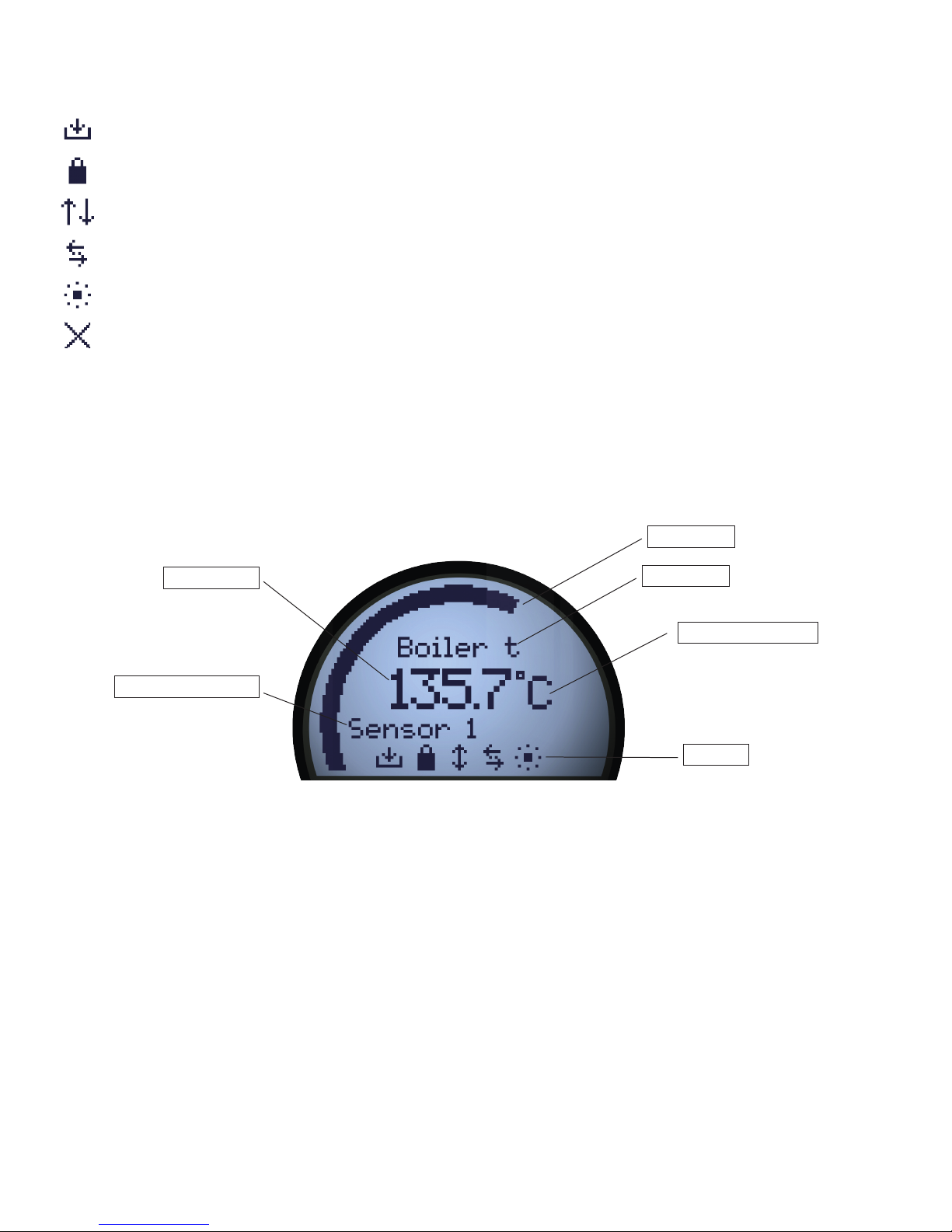
Device TAG
Symbols
Process value unit
Process value
Shown process value
Monitoring view
Bar graph
Symbol identification
The symbols bar provides information on the state of the device. Information such as HART communication, write protection
and process value tendency is shown.
Saving configuration to internal memory
Device is locked or write-protected
Current process value tendency indicators
External HART communication indicator
Internal communication indicator
External HART communication error
Monitoring view
Through the housing glass, you can easily monitor the process value in the configured units. A bar graph indicates the process
magnitude at a glance. The device tag is shown at the top of the display. The device tag makes it easy to identify the
displayed process value and it can be changed by pressing either the or 2 optical button. At the bottom of the display, the
symbols present information on the current state of the device.
Page 23
7501V107-UK 23
Programming view
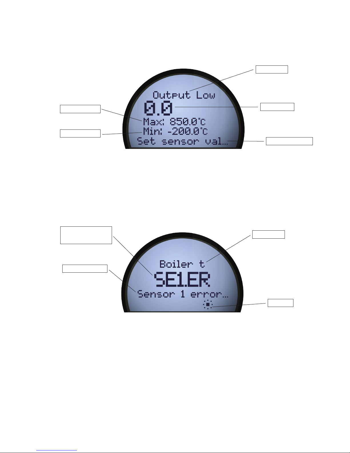
To enter the programming view, press and hold the and 2 optical buttons. The programming views will guide you in a fast
and intuitive way when setting up the device. The name of the selected parameter is shown at the top of the display with the
currently selected value just below. The value can be changed by pressing the or 2 optical buttons. Where applicable,
information on legal range and currently configured units will also be displayed. At the bottom, a scrolling help text will give
you information on the parameter you are modifying.
Diagnostics view
If a sensor error or device error occur, the display can be configured to flash in red or white backlight. The display will show the
type of status/error in large letters and a scrolling help text will present you with further information. The device tag is shown
at the top of the display and at the bottom the symbols bar indicates the state of the device. For a detailed description of the
different types of diagnostics messages shown please refer to the section Device and sensor status indication.
Configuration
When configuring the 7501, you will be guided through all parameters and you can choose the settings which fit the
application. For each menu there is a scrolling help text which is automatically shown in the display. Configuration is carried
out by use of the three optical buttons. When configuration is completed, or the display times out, the display will return to
monitor view.
Device TAG
Symbols
Error type indication
Flashing
Scrolling helptext
Diagnostics view
Menu name
Scrolling helptext
Actual value
Maximum value
Minimum value
Programming view
Page 24

24 7501V107-UK
Sensor status
3
Sensor 1 exceeds upper sensor limit IN.HI
3
Sensor 1 exceeds lower sensor limit IN.LO
3
Sensor 2 exceeds upper sensor limit IN.HI
3
Sensor 2 exceeds lower sensor limit IN.LO
3
CJC sensor exceeds upper CJC sensor limit IN.HI
3
CJC sensor exceeds lower CJC sensor limit IN.LO
3
Device and sensor status indication
The 7501 is capable of displaying diagnostics information for the sensors and the device. These diagnostics can be divided
into 4 categories: Sensor status, sensor errors, device status and device errors.
Sensor errors
Sensor 1 error SE1.ER
4
Sensor 2 error SE2.ER
4
CJC sensor error CJC.ER
4
Internal temperature sensor error CJC.ER
Device status
Configuration is being re-synchronized SYNC.DEV
5
New device attached and configuration is being updated NEW.DEV
5
Last process calibration failed CA.ER
6
Device errors
7
A/D converter error ADC.ER
7
EEPROM memory error EE.ER
7
RAM memory error RA.ER
7
Flash memory error FL.ER
7
Exception error during code execution SW.ER
7
Internal communication error COM.ER
7
3 The scrolling help text will inform you of the affected sensor.
4 Check wiring and replace sensor if necessary.
5 This message will disappear after a few seconds and the display will enter monitoring view.
6 Perform a new process calibration or reset the calibration to cancel this error. See the section Display.
7 A device malfunction has occurred. To clear this error, repower the device or reconfigure using the display. If the error is persistent, it will reappear
and the device may have to be replaced.
Page 25
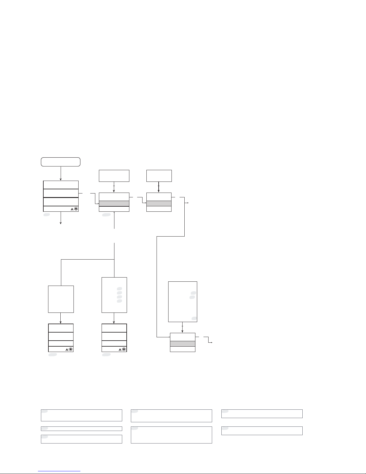
Power up
Sensor 1 - °C
123.45°C
Device tag
0000
PIN code
Txt 76
9999
0000
Yes
Adv Setup?
Txt 2
No
Yes
COM.ER
Txt 100
SW.ER
FL.ER
EE.ER
ADC.ER
RA.ER
COM.ER
SE1.ER
Txt 100
NEW.DEV
SYNC.DEV
SE1.ER
*
19
SE2.ER
*
19
CJC.ER
*
19
CA.ER
*
19
IN.HI
IN.LO
2 2
Device tag Device tag
3 3
*17
*1
*18
HART
Setup
Txt 4
Display
Tags
Calibration
*
15
Simulation
*
15
Sensor
HART
Write-protect
Language
HART revision
*
24
2
3
2
2
*28
7501V107-UK 25
Display menu
Exiting the monitor view allows you to configure the 7501, using the optical buttons (see the section Operating the optical
buttons). The display menu is divided into 2 parts: Basic configuration and Advanced configuration. The advanced
configuration menu is sub-divided into 9 parts: Display, Tags, Calibration, Simulation, Sensor, HART, Write-protect, Language
and HART Revision.
If the 7501 menu has been PIN code-protected by setting a PIN code different from 0000 in the display menu, the correct PIN
code must be entered to proceed to the desired configuration menu. The code 2008 will always give access to the menu.
The menu can be temporarily locked because it is receiving a configuration on the HART interface or because it is
synchronizing configuration parameters with the internal device.
If the 7501 has been write-protected it is still possible to proceed to the menu, but no changes can be made, and it is not
possible to save the configuration.
It is possible to change the write-protection state (enabled/disabled), but the correct write-protect password must be entered
when prompted.
If no keys are pressed for 60 s in any menu
(except for Sim and Cal), no parameters are
saved and the ”Monitor” menu is shown.
*1
*17
Will be forced into this state if any device
error occurs (from any other menu).
Warning state: will be forced into this state
if sensor error or overrange is present. Only
from ”Monitor” menu.
*18
Not shown if change of protocol is not
possible.
*24
First long press of and 2 simultaneously
will stop backlight flash but not exit view.
Second long press will enter configuration
menu (if allowed).
*19
No - continued on the
next page
and 2 toggles the
process variable shown
in line 2 and 3.
(The value configured
in display setup is
restored after 30
seconds.)
Continued on
page 28
Correct
Long
press
Long
press
Yes
Only shown if Write-protection is disabled.
*15
Only shown if pin-code is > 0000
*28
Page 26
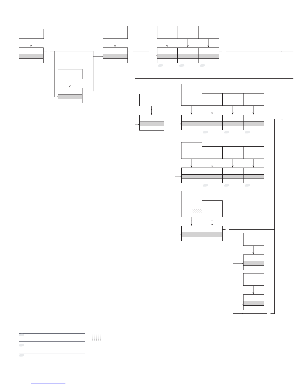
Single Sens
Sensor Func
Txt 3
Single Sens
Dual Sens
3-wire
Connection
Txt 7
2-wire
3-wire
4-wire
Temperature
Input Type
Txt 69
Voltage
Linear Res
Temperature
0
S1 Wire Res
Txt 8
100.0
0.0
0
S2 Wire Res
Txt 8
100.0
0.0
2 2 2 2 2
Differential
Meas setup
Txt 68
Average
Differential
2
Pt100
Pt Type
Txt 6
Pt50
Pt100
Pt200
Pt500
Pt1000
Custom
Pt
Sensor Type
Txt 70
Pt
Ni
TC
3-wire
Connection
Txt 7
2-wire
3-wire
4-wire
0
S1 Wire Res
Txt 8
100.0
0.0
2 2 2
2
0
S2 Wire Res
Txt 8
100.0
0.0
2
Ni100
Ni Type
Txt 71
Ni50
Ni100
Ni120
Ni1000
3-wire
Connection
Txt 7
2-wire
3-wire
4-wire
0
S1 Wire Res
Txt 8
100.0
0.0
2 2 2
0
S2 Wire Res
Txt 8
100.0
0.0
2
TC K
TC Type
Txt 72
TC B
TC E
TC J
TC K
TC L
TC N
TC R
TC S
TC T
TC U
TC W3
TC W5
TC Lr
Custom
Ext Pt100
CJC Type
Txt 10
Internal
Ext Pt100
Ext Ni100
Fixed
2 2
0
CJC Wire Res
Txt 8
100.0
0.0
2
0
CJC Wire Res
Txt 8
100.0
0.0
2
3
Pt
Ni
TC
3
3
3
3
3
3
3
3
3 3
*3 *5*4
*3 *5*4
*3 *5*4
26 7501V107-UK
Basic configuration
*4
Only shown if 2-wire sensor connection is
selected.
Only shown if single sensor function is
selected.
*3
Only shown if dual sensor function is
selected.
*5
Not available in
HART 5 mode
If connection is 3- or 4-wire, the max. cable
resistance is set to 10 Ohm.
This can be overwritten in the Advanced Menu.
Ext Pt 100
Ext Ni 100
Fixed
Internal
Single sensor
Dual sensor
Temperature
Voltage
Lin. R
Page 27
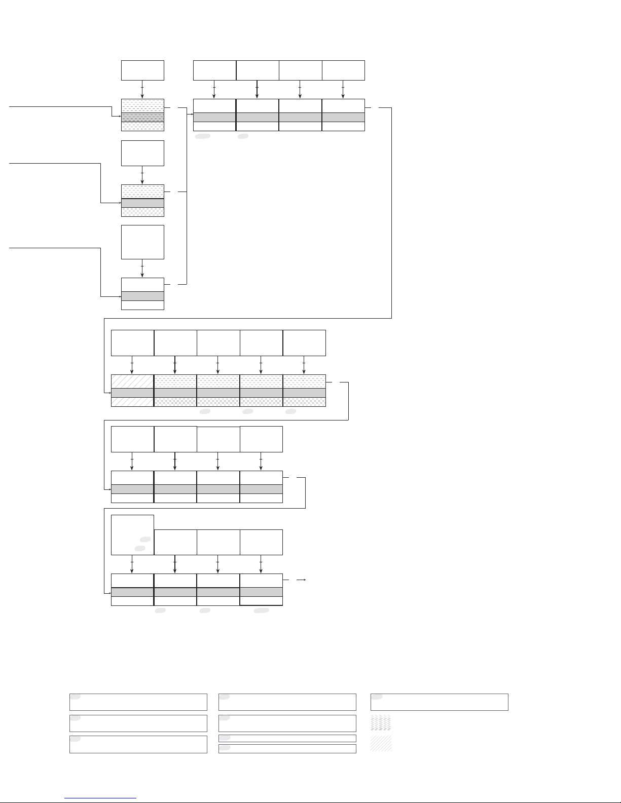
0
Fix CJC val
Txt 12
-40.0
135.0
2
200
Max Diff
Txt 15
-200
850
0
Output Low
Txt 21
-200
850
150
Output High
Txt 22
-200
850
Ohm
Unit
Txt 5
Ohm
kOhm
2 2 2 2
mV
Unit
Txt 5
uV
mV
V
2
°C
Unit
Txt 5
°C
°F
°Ra
K
2
1.0
PV Resp
Txt 9
1.0
60.0
1.0
S1 Resp
Txt 9
1.0
60.0
2 2
1.0
S2 Resp
Txt 9
1.0
60.0
2
1.0
Avg Resp
Txt 9
1.0
60.0
1.0
Diff Resp
Txt 9
1.0
60.0
2 2
3.50
Out Rng Lo
Txt 23
3.50
23.00
23.00
Out Rng Hi
Txt 24
3.50
23.00
2 2
3.50
Out Lim Lo
Txt 25
3.50
23.00
23.00
Out Lim Hi
Txt 26
3.50
23.00
2 2
Yes
Save ?
Txt 16
23.00
Out Broken
Txt 28
3.50
23.00
23.00
Out Shorted
Txt 29
3.50
23.00
2 2
Broken
Sens Error
Txt 27
Disabled
Broken
Shorted
*
23
Both
*
23
2
3
3
3
3
3
3
3
*8 *9
*5 *6*7
*6*21
Yes
No
2
*15
7501V107-UK 27
Not available in
HART 7 mode
*6
Only shown if differential sensor function is
selected.
*8
Only shown if sensor breakage detection is
activated.
Only shown if average sensor function is
selected.
*7
Only shown if sensor shortage detection is
activated.
*9
Only shown if dual sensor function is
selected.
*5
*21
Only shown if TC, fixed CJC is selected.
*23
Selection not available for Voltage Input Type
and TC Sensor Type with internal/fixed CJC.
Not available in
HART 5 mode
If HART revision = 5, units for S1, S2, Average and
Dierence are forced to either mV or Ohm.
Lin. R
Temperature
Voltage
“Monitor”
Only shown if Write-protection is disabled.
*15
Page 28
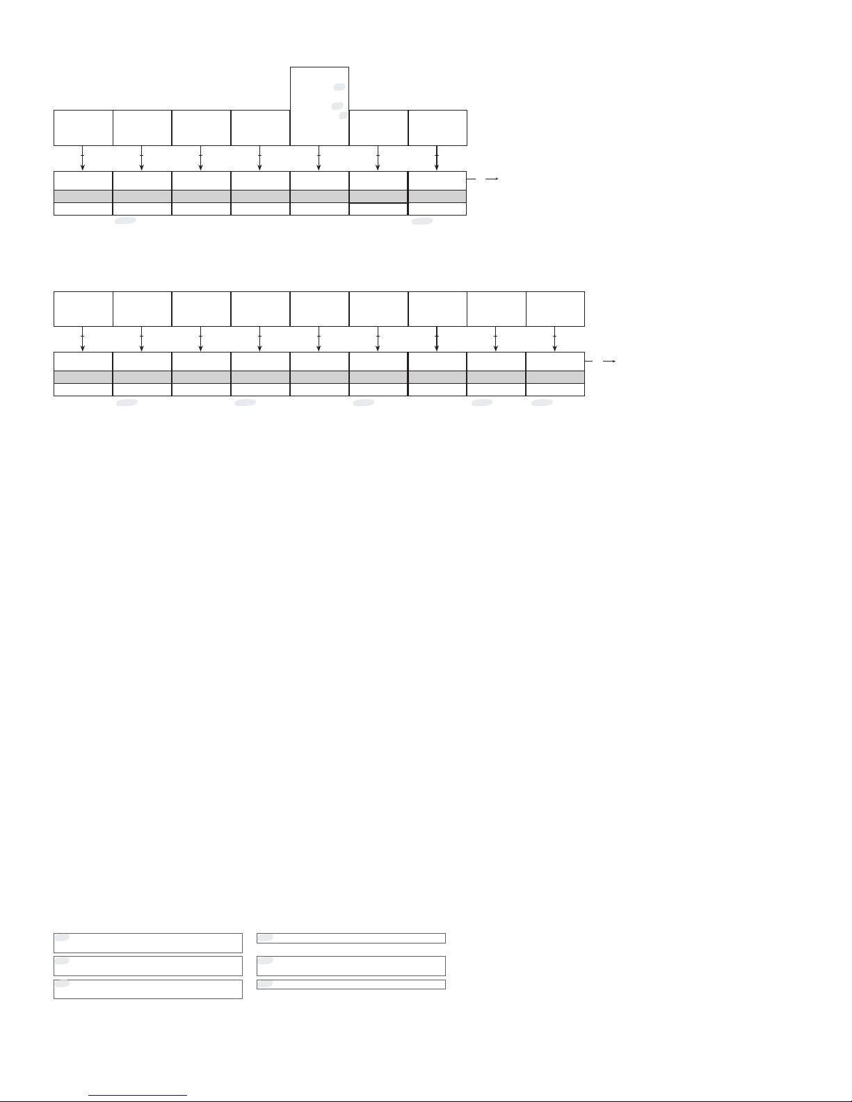
Yes
L Tag Setup?
Txt 64
No
Yes
Text
Long Tag
Txt 38
(Char list)
Yes
Save ?
Txt 16
2 2
Yes
Tag Setup?
Txt 65
No
Yes
Text
Tag
Txt 39
(Char list)
2 2
Yes
Msg Setup?
Txt 67
No
Yes
Text
Message
Txt 35
(Char list)
2 2
Yes
Descr Setup?
Txt 66
No
Yes
Text
Descriptor
Txt 34
(Char list)
2 2
3
*16 *16 *16 *16
Yes
No
2
White
Backlight
Txt 42
Off
White
Red
White
Error color
Txt 73
Off
White
Red
3
Contrast
Txt 43
0
9
2 2 2
% Range
Bar graph
Txt 44
Loop Curr
% Range
Sensor 2
Monitor
Txt 45
Sensor 1
Sensor 2
*
5
CJC Sensor
Average
*
7
Differential
*
6
Loop Curr
% Range
2 2
3
*25
Yes
Save ?
Txt 16
Yes
No
2
0000
PIN code
Txt 77
9999
0000
2
*15
*15
28 7501V107-UK
Display
Tags
*25
Not shown if backlight is off.
Only shown if ”Yes” was selected in the
previous menu.
*16
*6
Only shown if differential sensor function is
selected.
Only shown if dual sensor function is
selected.
*5
Only shown if average sensor function is
selected.
*7
“Monitor”
“Monitor”
Only shown if Write-protection is disabled.
*15
Page 29
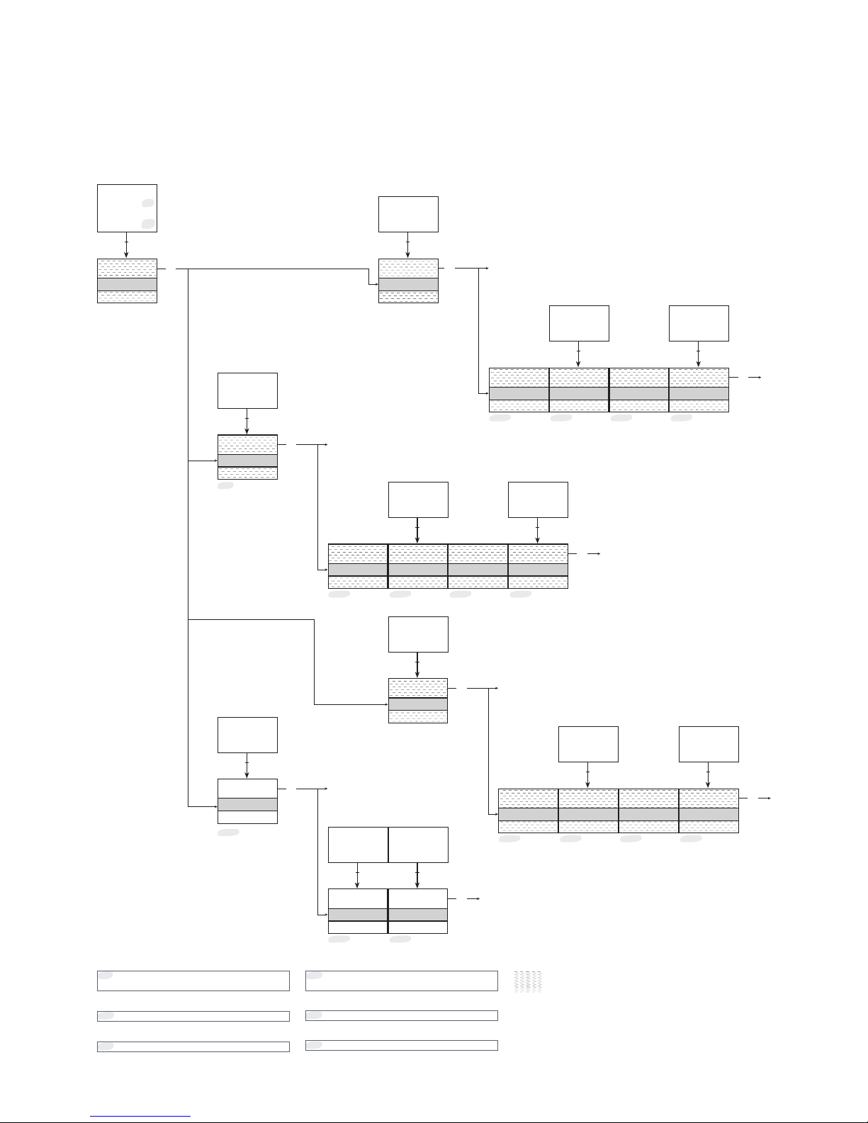
Sensor 2
Calibration
Txt 53
Sensor 1
Sensor 2
*
5
CJC sensor
Loop Curr
*
26
2
Do Calib
S2 Calib
Txt 54
Reset Calib
Do Calib
2
Do Calib
Loop Calib
Txt 54
Reset Calib
Do Calib
2
3
*5
Set S2 Low
Txt 74
0.0
S2 Cal Low
Txt 55
-200°C
850°C
2
*27 *14
4.00
Calib 4 mA
Txt 55
3.50 mA
23.00 mA
20.00
Calib 20 mA
Txt 56
3.50 mA
23.00 mA
2 2
*12 *13
Do Calib
S1 Calib
Txt 54
Reset Calib
Do Calib
2
Do Calib
CJC Calib
Txt 54
Reset Calib
Do Calib
2
Set S1 Low
Txt 74
0.0
S1 Cal Low
Txt 55
-200°C
850°C
2
*27 *14
Set CJC Low
Txt 74
0.0
CJC Cal Low
Txt 55
-40.0
135.0
2
*27 *14
3
3
3
3
3
3
3
3
Set S2 High
Txt 75
*27
100.0
S2 Cal High
Txt 56
-200°C
850°C
2
*14
Set S1 High
Txt 75
*27
100.0
S1 Cal High
Txt 56
-200°C
850°C
2
*14
Set CJC High
Txt 75
*27
100.0
CJC Cal Hi
Txt 56
-40.0
135.0
2
*14
*26
7501V107-UK 29
Calibration
(only if Write-protection is disabled)
The device can be process-calibrated in two points to fit a given input signal. A low input signal (not necessarily 0%) is applied
and the actual value is entered. Secondly a high input signal (not necessarily 100%) is applied and the actual value is entered.
If you accept to use the calibration (by selecting Yes in the Save menu) the device will work according to the new adjustments.
You can return the device to factory calibration points by selecting Reset Calibration from the Calibration menu. Please note
that while performing a calibration the programming mode will not time out.
Only shown if dual sensor function is
selected.
*5
*13
20 mA fixed output configured internally.
4 mA fixed output configured internally.
*12
Default value is current input value.
No timeout in this menu.
*14
*26
Not possible if Loop Current is not active.
*27
No timeout in this menu.
Not available in
HART 5 mode
Sensor 2
Loop Curr
Sensor 1
CJC sensor
Reset Calib
Do Calib
Reset Calib
Do Calib
Reset Calib
Do Calib
Reset Calib
Do Calib
“Monitor”
“Monitor”
“Monitor”
“Monitor”
“Monitor”
“Monitor”
“Monitor”
“Monitor”
Page 30
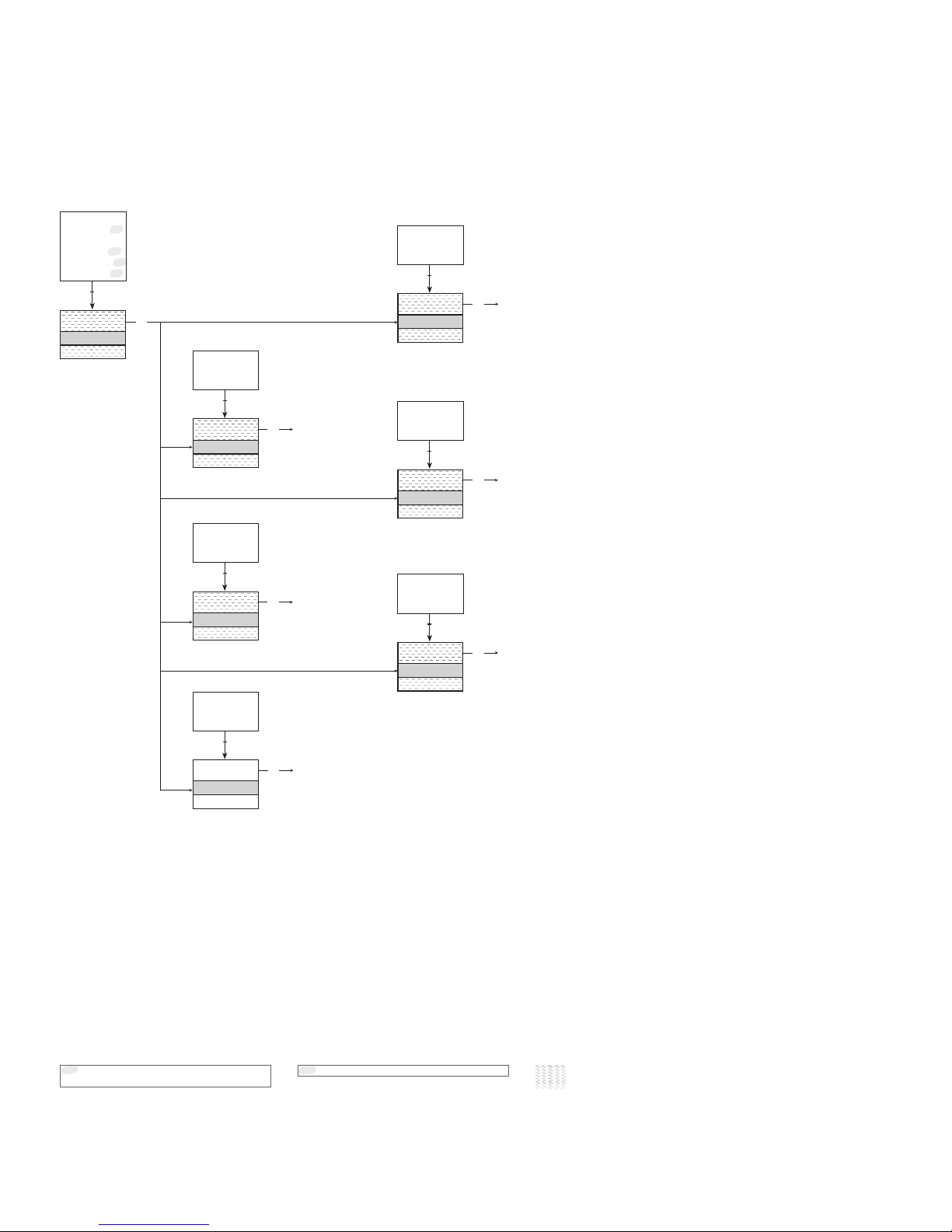
Sensor 2
Simulation
Txt 57
Sensor 1
Sensor 2
*
5
CJC Sensor
Average
*
5
Differential
*
5
Loop Curr
*
26
2
20.0
S2 Simul
Txt 59
-200.0
850.0
2
20.0
Avg Simul
Txt 61
-200.0
850.0
2
3
20.00
Loop Test
Txt 63
3.5 mA
23.0 mA
2
20.0
S1 Simul
Txt 58
-200.0
850.0
2
20.0
CJC Simul
Txt 60
-40.0
135.0
2
20.0
Diff Simul
Txt 62
-200.0
850.0
2
3
3
3
3
3
3
30 7501V107-UK
Simulation
(only if Write-protection is disabled)
The 7501 allows you to simulate process values by entering the simulation menu. Using the and 2 optical buttons, the
simulated value can be increased and decreased (see the section Operating the optical buttons). Please note that while
performing a calibration the display will not time out.
Only shown if dual sensor function is
selected.
*5
Not available in
HART 5 mode
*26
Not possible if Loop Current is not active.
Sensor 2
Average
Sensor 1
CJC sensor
Dierential
Loop Test
“Monitor”
“Monitor”
“Monitor”
“Monitor”
“Monitor”
“Monitor”
Page 31
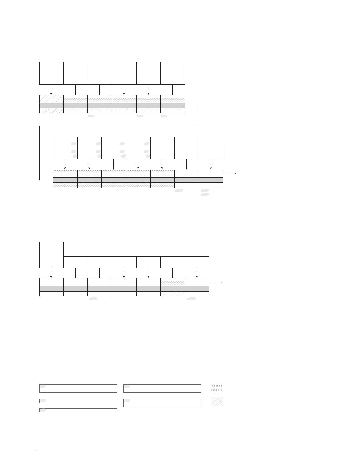
mV
PV Unit
Txt 5
All units
mV
S1 Unit
Txt 5
All units
2 2
mV
S2 Unit
Txt 5
All units
°F
CJC Unit
Txt 5
°C
°F
K
°Ra
Yes
Save ?
Txt 16
2 2
mV
Avg Unit
Txt 5
All units
mV
Diff Unit
Txt 5
All units
2 2
Sensor 2
Assign TV
Txt 19
Sensor 1
Sensor 2
*
5
CJC Sensor
Average
*
5
Differential
*
5
Sensor 2
Assign QV
Txt 20
Sensor 1
Sensor 2
*
5
CJC Sensor
Average
*
5
Differential
*
5
2 2
Sensor 2
Assign PV
Txt 17
Sensor 1
Sensor 2
*
5
CJC Sensor
Average
*
5
Differential
*
5
Sensor 2
Assign SV
Txt 18
Sensor 1
Sensor 2
*
5
CJC Sensor
Average
*
5
Differential
*
5
2 2
3
*5*5 *5
1.0
CJC Resp
Txt 9
60.0
1.0
2
*20
*22
0
Max Wire Res
Txt 14
100.0
0.0
2
Yes
No
2
*15
Req preamb
Dev info
Txt 50
Req Preamb
SW Rev
HW Rev
Device ID
Manuf ID
HART Rev
5
Resp Preamb
Txt 31
5
20
2 2
0
Poll Addr
Txt 32
0
63
Yes
Loop Enable
Txt 33
No
Yes
Yes
Save ?
Txt 16
2 2
3
*11
Yes
No
2
0
Assembly Nr
Txt 37
0
16777215
01-06-2015
Date
Txt 36
DD-MM-YYYY
2 2
*15
7501V107-UK 31
Sensor
The sensor menu allows you to make more detailed configuration of your sensor values, which are not available in the basic
configuration menu. These involve selecting from a large amount of process variable units, changing the sensor assignment to
PV, SV, TV and QV and specifying the CJC response time. Please note that performing a basic configuration (see the section
Basic configuration) will overwrite these changes.
HART
Under this menu you will find special parameters pertaining to HART. It will provide you with general information regarding
number of request preambles, software and hardware revisions, device and manufacture IDs and HART revision. The menu
will also allow you to specify number of response preambles, polling address, assembly number and date.
Only shown if dual sensor function is
selected.
*5
*11
Range is 0...15 in HART 5 mode.
Values may be owerwritten when normal
menu is saved.
*20
Only shown if 3- or 4-wire connection is
selected.
*22
Not available in
HART 7 mode
Not available in
HART 5 mode
“Monitor”
“Monitor”
Only shown if Write-protection is disabled.
*15
Page 32
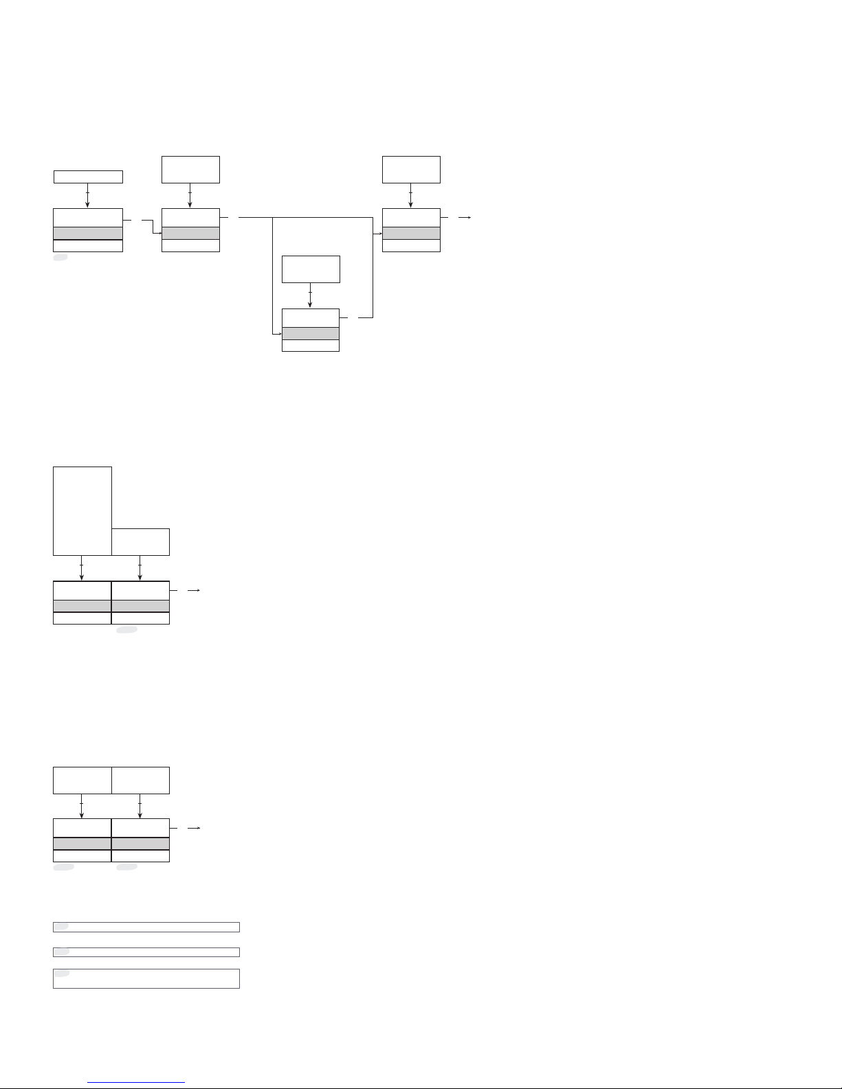
Yes
Save ?
Txt 16
Yes
Enable WP
Txt 47
Yes
No
2
3
********
New Password
Txt 48
(Char list)
2
3
3
Yes
No
2
********
Password
Txt 1
3
(Char list)
2
Yes
Save ?
Txt 16
Dansk
Language
Txt 41
English
Dansk
Deutsch
Français
Svenska
Italiano
Español
2
3
Yes
No
2
*15
Yes
Save ?
Txt 16
HART 7
HART Rev
Txt 51
3
HART 7
HART 5
2
*24
Yes
No
2
*15
*2
32 7501V107-UK
Write-protect
Here you can choose to enable or disable write protection using a password. If write-protection is already enabled, the correct
password must be entered to get access. The password must consist of exactly 8 characters, available in the Latin 1 character
set, and will protect the device against unauthorized modifications to the configuration. The device is delivered default with
write-protection disabled. The password 00002008 always allows access to the write-protection menu.
Language
In this menu you can choose between seven different language versions of the help text that will appear in the menu (see the
section Display). You may choose from the following languages: English, Dansk, Deutsch, Français, Svenska, Italiano and
Español.
HART Revision
Changing the HART revision is done from this menu. Select the desired HART revision and press the button. Select Yes to
effect the change in the Save menu. Please note that changing the HART revision will reboot the device, during which time
the display may become blank for a few seconds. If HART 7 is selected the device will appear as 7501 in the HART interface.
If HART 5 is selected the device will appear as 7501H5/5335V2 in the HART interface.
Not shown if change of protocol is not
possible
*24
“Monitor”
“Monitor”
No
Yes
“Monitor”
Correct
Only shown if Write-protection is disabled.
*15
Only shown if Write-protection is enabled.
*2
Page 33

7501V107-UK 33
Help text overview
[01]
[02]
[03]
[04]
[05]
06]
[07]
[08]
[09]
[10]
[12]
[13]
[14]
[15]
[16]
[17]
[18]
[19]
[20]
[21]
[22]
[23]
[24]
[25]
[26]
[27]
[28]
[29]
[31]
[32]
[33]
[34]
[35]
[36]
[37]
[38]
[39]
[41]
[42]
[43]
[44]
[45]
[47]
[48]
[50]
[51]
Set correct password
Enter Advanced setup menu?
Select single sensor functionality
Select dual sensor functionality
Enter Display setup
Enter Tags setup
Enter Process calibration
Enter Simulation mode
Enter Advanced sensor setup
Enter HART setup
Enter Write-protect setup
Enter Language setup
Enter HART Revision setup
Select measurement unit
Select custom RTD as sensor type
Select Pt50 as sensor type
Select Pt100 as sensor type
Select Pt200 as sensor type
Select Pt500 as sensor type
Select Pt1000 as sensor type
Select 2-Wire sensor connection
Select 3-Wire sensor connection
Select 4-Wire sensor connection
Set actual cable resistance in 2 wires
Set response time
Select Internal CJC sensor
Select Pt100 as external CJC sensor type
Select Ni100 as external CJC sensor type
Select Fixed CJC
Set fixed CJC value
Disable sensor 2
Enable sensor 2
Set maximum cable resistance in 2 wires
Set max. value for individual sensors for
differential measurement
Save configuration?
Map sensor1 to PV and output loop current
Map sensor2 to PV and output loop current
Map CJC sensor to PV and output loop current
Map Internal temperature to PV and output loop
current
Map Avg measument to PV and output loop current
Map differential measurement to PV and output loop
current
Map sensor1 to SV
Map sensor2 to SV
Map CJC sensor to SV
Map Internal temperature to SV
Map Avg measument to SV
Map differential measurement to SV
Map sensor1 to TV
Map sensor2 to TV
Map CJC sensor to TV
Map Internal temperature to TV
Map Avg measument to TV
Map differential measurement to TV
Map sensor1 to QV
Map sensor2 to QV
Map CJC sensor to QV
Map Internal temperature to QV
Map Avg measument to QV
Map differential measurement to QV
Set sensor value for analog output low
Set sensor value for analog output high
Set output current at 0% input range
Set output current at 100% input range
Set output current lower limit
Set output current upper limit
Disable sensor error detection
Enable sensor wire breakage detection
Enable sensor shortage detection
Enable both sensor wire breakage and sensor
shortage detection
Set output current in case of sensor wire breakage
Set output current in case of sensor shortage
Set number of preambles in HART response frames
Set polling address
Disable loop current signal (no analog output)
Enable loop current signal (analog output)
Write description of the device
Write message on the device
Set user date on device
Set the final assembly number
Write long tag
Write tag
Select language
Disable LCD backlight
Select white LCD backlight
Select red LCD backlight
Adjust LCD contrast
Select loop current for bar graph indicator
Select % of range for bar graph indicator
Select Sensor1 for process monitor view
Select Sensor2 for process monitor view
Select CJC Sensor for process monitor view
Select Average measurement for process monitor
view
Select differential measurement for process monitor
view
Select loop current for process monitor view
Select % of range for process monitor view
Enable write protection?
Set new password
Minimum number of preambles in requests
Software revision level
Hardware revision level
Device identification
Manufacturerer identification
HART protocol revision level
Set HART protocol revision 7
Set HART protocol revision 5
Page 34

34 7501V107-UK
Enter sensor1 calibration menu
Enter sensor2 calibration menu
Enter CJC sensor calibration menu
Enter output loop current calibration menu
Reset calibration to factory default
Perform process calibration
Set value for low calibration point
Set value for high calibration point
Simulate sensor1 input
Simulate sensor2 input
Simulate CJC sensor input
Simulate average measurement
Simulate differential measurement
Simulate output loop current
Set sensor1 simulation value
Set sensor2 simulation value
Set CJC sensor simulation value
Set average measurement simulation value
Set differential measurement simulation value
Set output loop current simulation value
Edit the long tag?
Edit the tag?
Edit the descriptor?
Edit the message?
Select averaging of sensor 1 and sensor 2
Select differential measurement:
sensor 1 - sensor 2
Select voltage input
Select linear resistance input
Select temperature input
Select Pt sensor type
Select Ni sensor type
Select TC sensor type
Select Ni50 as sensor type
Select Ni100 as sensor type
Select Ni120 as sensor type
Select Ni1000 as sensor type
Select TC-B as sensor type
Select TC-E as sensor type
Select TC-J as sensor type
Select TC-K as sensor type
Select TC-L as sensor type
Select TC-N as sensor type
Select TC-R as sensor type
Select TC-S as sensor type
Select TC-T as sensor type
Select TC-U as sensor type
Select TC-W3 as sensor type
Select TC-W5 as sensor type
Select TC-Lr as sensor type
Select Custom TC as sensor type
Disable LCD error backlight
Select white LCD error backlight
Select red LCD error backlight
Apply low calibration point value and wait until
stable
Apply high calibration point value and wait until
stable
[53]
[54]
[55]
[56]
[57]
[58]
[59]
[60]
[61]
[62]
[63]
[64]
[65]
[66]
[67]
[68]
[69]
[70]
[71]
[72]
[73]
[74]
[75]
[76]
[77]
[100]
SW.ER
FL.ER
EE.ER
ADC.ER
RA.ER
COM.ER
NEW.DEV
CO N F. ER
SE1.ER
SE2.ER
CJC.ER
CJC.ER
CA.ER
IN.HI / IN.LO
IN.HI / IN.LO
IN.HI / IN.LO
IN.HI / IN.LO
Set menu access PIN-code
Set menu access PIN-code (0000 will disable)
Exception error during code execution
Flash memory error
EEPROM memory error
A/D converter error
RAM memory error
Internal communication error
New device attached – configuration is being
updated – please wait
Configuration is being re-synchronized - please wait
Sensor 1 error, check wiring and replace sensor if
necessary
Sensor 2 error, check wiring and replace sensor if
necessary
CJC Sensor error, check wiring and replace sensor if
necessary
Internal temperature sensor error
Last process calibration failed to succeed - please
retry
Sensor 1 is out of range
Sensor 2 is out of range
CJC sensor is out of range
Sensor 1 or Sensor 2 measurement is out of range
Page 35

7501V107-UK 35
Available units
The following table lists the available units. Please note that most of these are only available from the Sensor menu (see the
section Display menu).
Menu # HART # Text Types
0 32 °C <- Sensor specific types
1 33 °F
2 34 °R
3 35 K
4 37 Ohm
5 163 kOhm
6 240 µV
7 36 mV
8 58 V
9 39 mA
10 57 %
11 1 inH
2
O <- Pressure units
12 2 inHg
13 3 ftH
2
O
14 4 mmH
2
O
15 5 mmHg
16 6 psi
17 7 bar
18 8 mbar
19 9 g/cm
2
20 11 Pa
21 12 kPa
22 13 torr
23 14 atm
24 237 MPa
25 17 l/min <-Volume flow units
26 19 m
3
/h
27 22 gal/s
28 24 l/s
29 25 ml/d
30 26 ft
3
/s
31 130 ft
3
/h
32 27 ft
3
/d
33 28 m
3
/s
34 29 m
3
/d
35 121 m
3
n/h
36 132 bbl/s
37 134 bbl/h
38 135 bbl/d
39 136 gal/h
40 138 l/h
41 235 gal/d
42 20 ft/s <-Velocity units
43 21 m/s
44 114 in/s
45 120 m/h
Menu # HART # Text Types
46 40 gal <- Volume units
47 41 l
48 43 m
3
49 46 bbl
50 110 bush
51 111 yd
3
52 112 ft
3
53 113 in
3
54 166 m3n
55 167 ln
56 236 hl
57 44 ft <- Length units
58 45 m
59 47 in
60 48 cm
61 49 mm
62 50 min <-Time units
63 51 s
64 52 h
65 53 d
66 60 g <- Mass units
67 61 kg
68 62 t
69 63 lb
70 64 ShTon
71 65 LTo n
72 125 oz
73 70 g/s <- Mass flow units
74 71 g/min
75 72 g/h
76 73 kg/s
77 75 kg/h
78 76 kg/d
79 77 t/min
80 78 t/h
81 79 t/d
82 80 lb/s
83 82 lb/h
84 83 lb/d
85 90 SGU <- Mass per volume units
86 91 g/cm
3
87 92 kg/m
3
88 95 g/ml
89 96 kg/l
90 97 g/l
91 146 µg/L
Page 36

36 7501V107-UK
Menu # HART # Text Types
92 147 µg/m
3
93 54 cSt <- Viscosity units
94 55 cP
95 69 N/m <- Energy (work) units
96 128 kW/h
97 162 Mcal
98 164 MJ
99 165 Btu
100 127 kW <- Power units
101 129 hp
102 141 MJ/h
103 142 Btu/h
104 117 deg/s <- Angular velocity units
105 118 rev/s
106 119 rpm
107 38 Hz <- Miscellaneous
108 56 µMho
109 59 pH
110 66 mS/cm
111 67 µS/cm
112 68 N
113 139 ppm
114 143 deg
115 144 rad
116 148 %Cs
117 149 Vol%
118 153 pF
119 154 ml/l
120 155 µl/l
121 161 %LEL
122 169 ppb
123 251 <blank>* <- Special units
124 252 ?
125 253 Spcl
*No characters shown
Page 37
7501V107-UK 37
Programming
The 7501 can be configured in one of the following 3 ways:
• Via the optical buttons and the display (see the section Display menu).
• With a HART modem and the PReset software.
• With a HART compliant handheld communicator having the 7501H5 or 7501H7 DD driver installed.
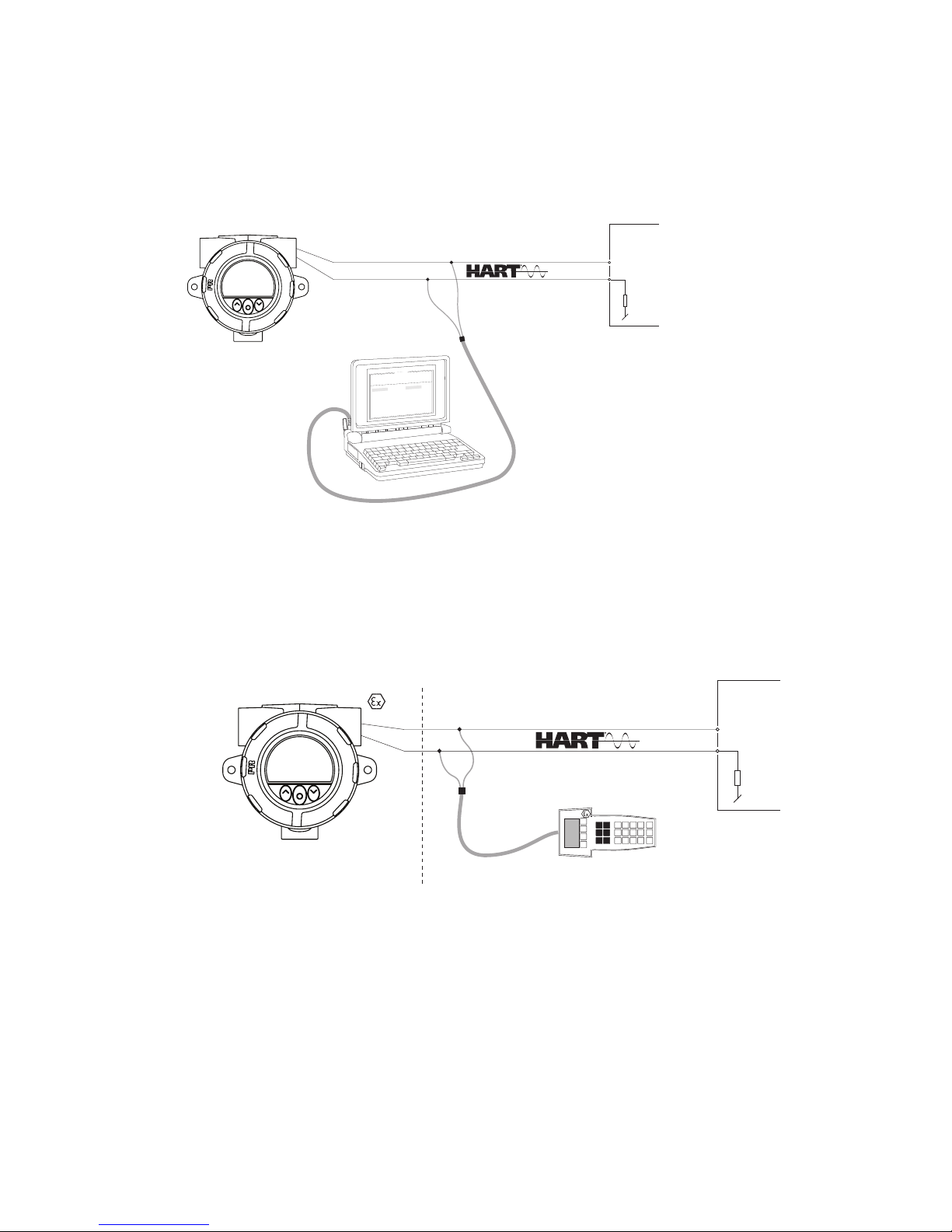
1: HART modem
For programming please refer to the drawing below.
2: HART communicator
For programming please refer to the drawing below. To get access to product-specific commands, the HART communicator
must be loaded with the 7501 H5 / 7501 H7 DD driver. This can be ordered either from the HART Communication Foundation
or from PR electronics.
1
2
F
i
l
e
P
r
o
d
u
c
t
I
n
p
u
t
O
u
t
p
u
t
C
o
m
m
u
n
i
c
at
i
o
n
L
a
n
g
u
a
g
e
O
p
t
i
o
n
0
8
:
3
0
:
0
0
P
R
e
t
o
p
5
3
3
1
D
a
t
e
:
1
9
9
4
-
8
-
1
0
9
4
3
2
0
1
5
9
4
P
R
e
l
e
c
t
r
o
n
i
cs
A
n
a
l
o
g
i
n
p
u
t
A
n
a
l
o
g
o
u
t
p
u
t
S
e
r
i
al
n
o
:
I
n
p
u
t
t
y
p
e
:
O
u
t
p
u
t
t
y
p
e
:
4
-
2
0
m
A
U
p
s
ca
l
e
S
e
n
so
r
e
r
r
o
r
:
P
t
1
0
0
D
I
N
/
I
E
C
0
.
0
0
-
5
0
.
0
0
C
3
-
w
i
r
e
1
.
0
0
s
e
c
-
-
-
-
-
-
I
n
p
u
t
r
a
n
g
e
:
C
o
n
n
e
ct
i
o
n
:
C
o
l
d
j
u
n
c
t
i
o
n
c
o
m
p
:
R
e
s
p
o
n
s
e
t
i
m
e
:
T
ag
n
o
:
7501
+Vsupply
Input
Receiving
equipment
HART modem
250 Ω <
Rload<1100 Ω
1
2
7501
Safe area
+Vsupply
Input
Receiving
equipment
area
250 Ω <Rload<1100 Ω
Page 38
38 7501V107-UK
Changing the HART protocol version
It is possible to change the HART protocol revision of the device by means of the display, utilizing the PReset software and a
HART modem or other HART configuration tools such as handheld HART terminals.
Changing the HART revision using the display and the optical buttons
Changing the revision is done from the HART revision view under the Advanced menu. Use the or 2 optical buttons to
select the desired HART revision. Press the button to accept the revision and change to the Save view. Select Yes and press
to acknowledge the change or No to cancel.
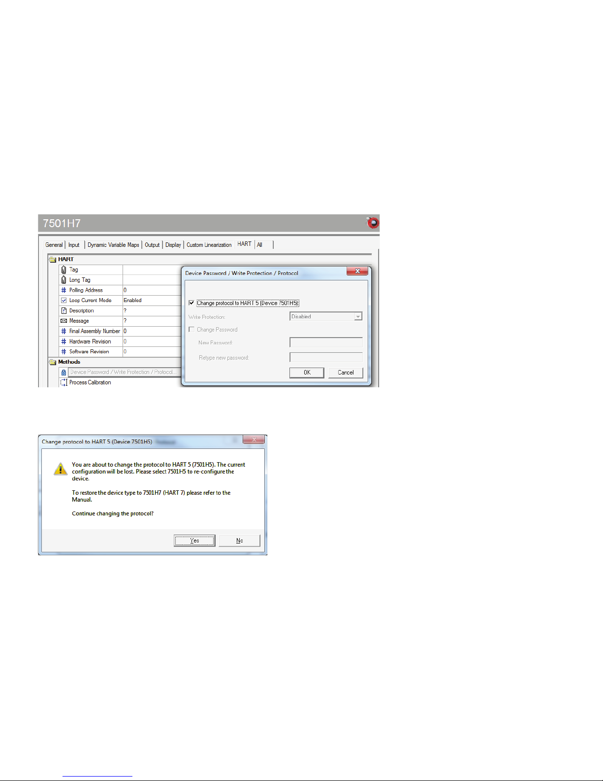
Changing the HART revision using the PReset software
Select either 7501H5 or 7501H7 depending on which protocol revision the 7501 is currently running. Click on the HART tab
and then on Device Password / Write Protection / Protocol…. In the newly opened window check the “Change protocol to
HART #” (# being the desired revision) then acknowledge by pressing the OK button.
The following warning appears:
Click Yes to accept the changes.
Changing the HART revision using a handheld terminal
• Drive the 7501 device Online and enter Device setup – Diag/Service.
• Select Write protection and Write protect by entering “********” (eight stars).
• Select New password - type “********” (eight stars) and then “HARTREV5” or “HARTREV7” depending on the desired
revision
• Select Write enable and enter “-CHANGE-”.
Page 39
7501V107-UK 39
Connection of transmitters in multidrop mode
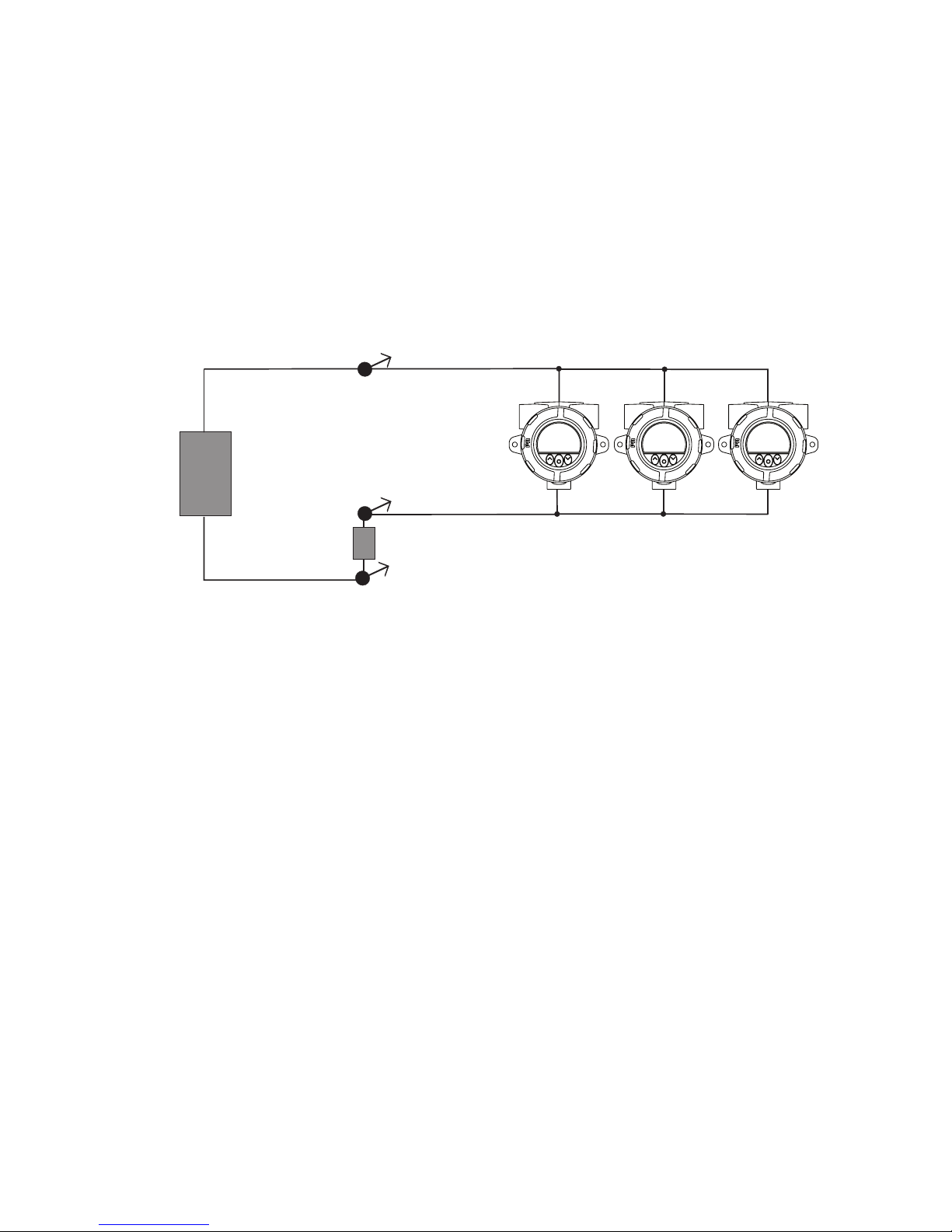
The outputs of maximum 63 transmitters can be connected in parallel for a digital HART 7 communication on 2-wires. For
HART 5 the outputs of maximum 15 transmitters can be connected in the same way.
Before they are connected, each transmitter must be configured with a unique polling address ranging from one to 63 (HART
7) or 15 (HART 5). If two transmitters are configured with the same address, both will be excluded. The transmitter must be
configured for multidrop mode (with a fixed output signal of 4 mA). The maximum current in the loop is therefore 252 mA
(HART 7) or 60 mA (HART 5).
The communication is done by means of either a HART communicator or a HART modem.
The PReset configuration software can configure the individual transmitter for multidrop mode and provide it with a unique
polling address.
The HART communicator or HART modem can be connected across AB or BC.
R
A
B
C
+
-
+
-
7501
7501
7501
Power
supply
Max. 63 transmitters (HART 7)
or max. 15 transmitters (HART 5)
Rload
> 250 Ω, < 1100 Ω
Page 40
A/F = 5
7
G
F
E
1
7 5 3
H
RF
Al
B
A
40 7501V107-UK
Retrofit
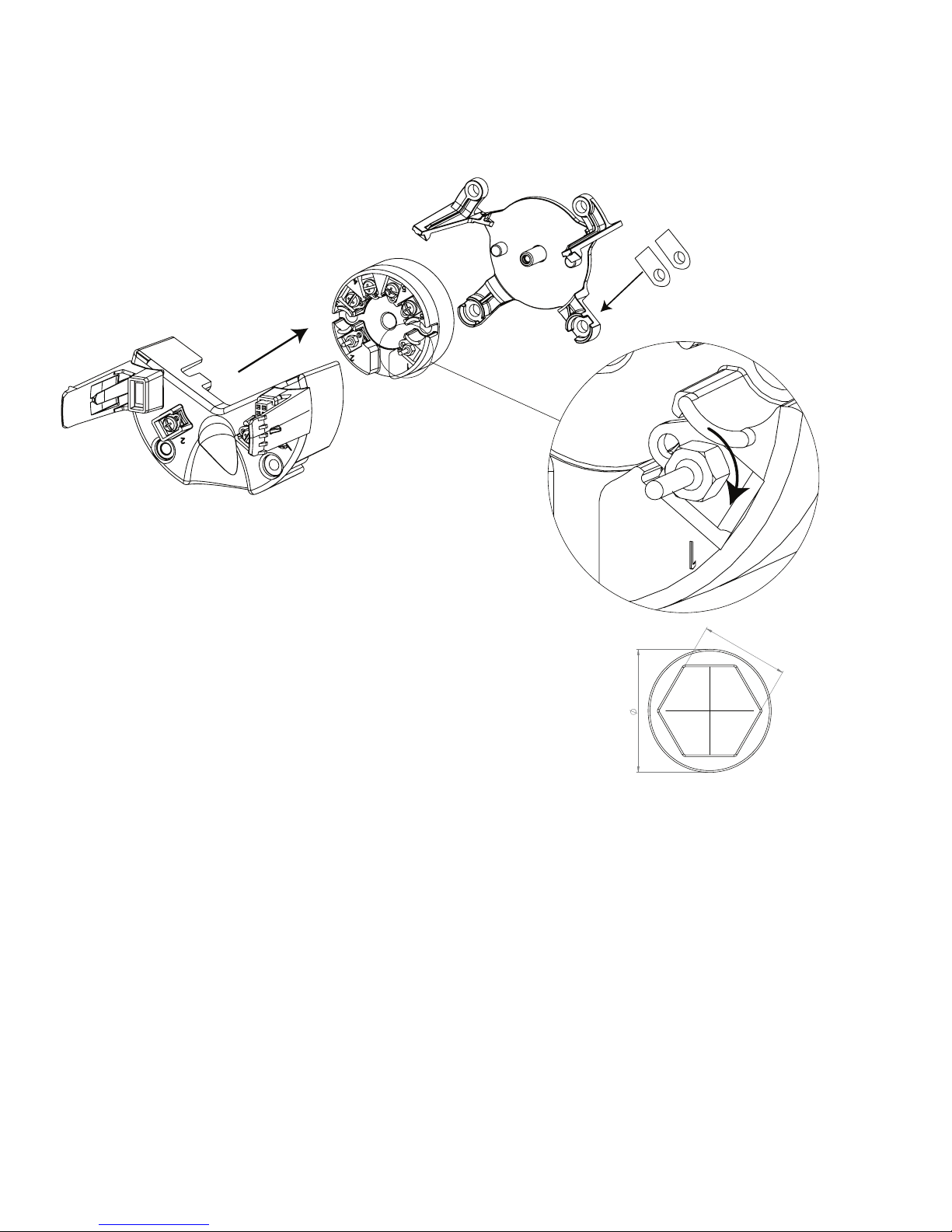
The 7501 can be retrofitted with any 5335 or 5337 transmitter. This allows for easy use of existing devices. The following
gives you a short guide on how to perform this task.
Before proceeding please refer to the section Assembly and disassembly for information on extracting and reassembling the
main unit. Then follow the three easy steps below.
NB. The fixation bracket (marked B on the drawing) is not interchangeable
between the aluminum and stainless steel housing. Check the bottom right-hand
corner for identifier (Al for aluminum and RF for stainless steel).
1. On the 5335 / 5337, remove the terminal 1 and 2 screws using a screwdriver.
2. Attach the connector pins to the 5335 / 5337 connector 1 and 2.
Tighten the screws using a nutdriver or a socket wrench with Across Flats (A/F)
of 5 mm and an outer diameter of no more than 7 mm.
Screw torque on connector pins = 0.4 Nm.
3. Mount the device in the main unit, making sure the connectors meet.
The first time power is applied to the retrofitted 7501, it will synchronize with the configuration parameters from the
attached 5335 / 5337. This process will take approximately 30 seconds and during this NEW.DEV will appear in the display.
Warning:
For Ex installation the customer must assure that the installed transmitter has all the necessary approvals applicable for the
place of installation.
Once a 5335 / 5337 unit which has been fitted into the 7501, it must not be taken out and used in other applications.
Nutdriver / socket wrench head
Page 41

Appendix
ATEX Installation Drawing
IECEx installation drawing
FM Installation Drawing
CSA Installation Drawing
Desenho de Instalaçao INMETRO
7501V107-UK 41
Page 42
42 7501V107-UK
7501QA01
LERBAKKEN 10, 8410 RØNDE DENMARK. WWW.PRELECTRONICS.COM
Revision date:
2015-11-03
Version Revision
V2R0
Page:
1/6
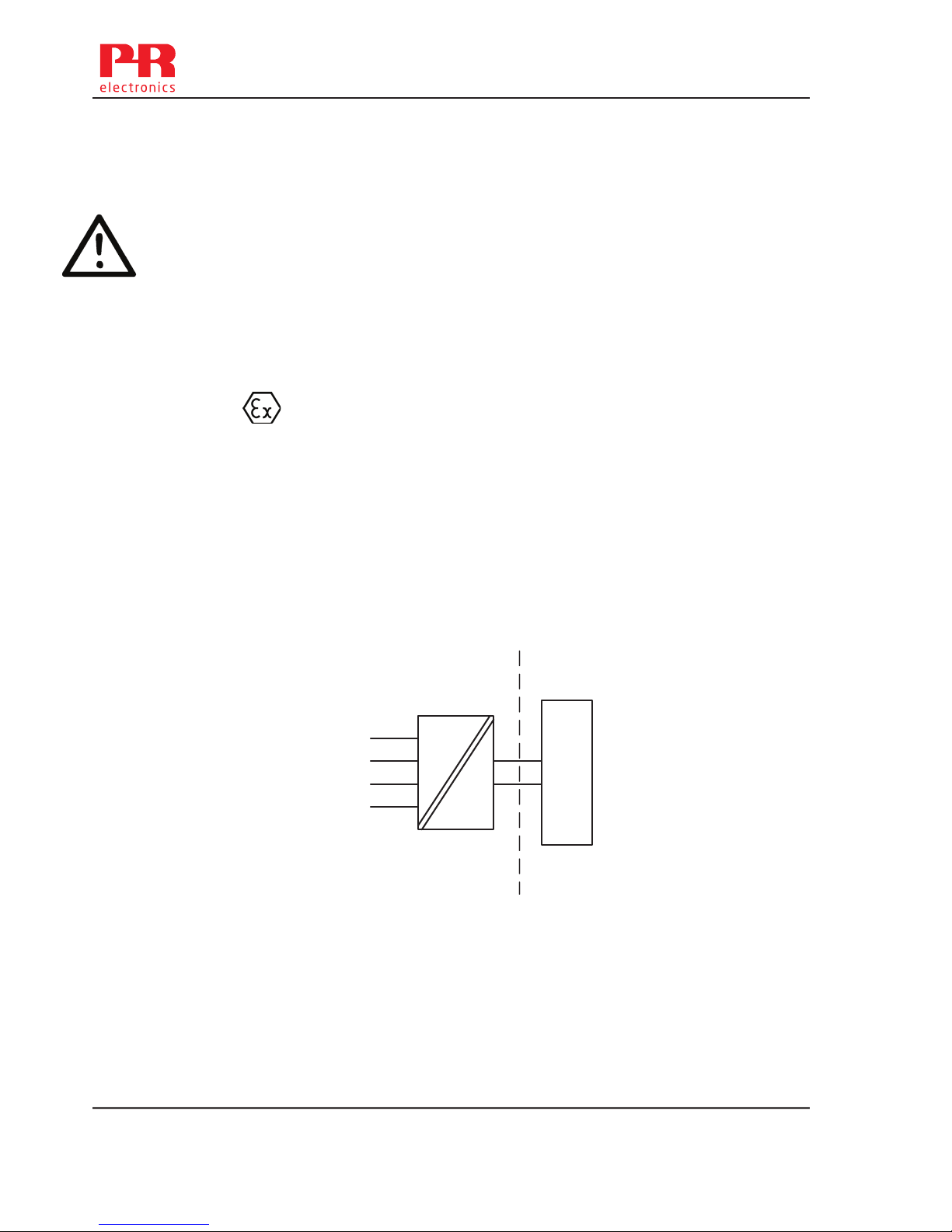
7501 ATEX Installation
For safe installation of 7501 the following must be observed. The module shall only be installed by
qualified personnel who are familiar with the national and international laws, directives and
standards (EN60079-14) that apply to this area.
Year of manufacture can be taken from the first two digits in the serial number.
Ex ia installation:
ATEX Certificate
DEKRA15ATEX0058X
Marking
Standards: EN 60079-0: 2012, EN 60079-11: 2012
Non Hazardous Area
Hazardous area
Zone 0, 1, 2, 20, 21, 22, (Mines)
II 1 G Ex ia IIC T6...T4 Ga
II 1 D Ex ia IIIC T100°C Da
I M1 Ex ia I Ma ( 7501B )
Sensor
Terminal: 3,4,5,6
Uo: 9.6 VDC
Io: 28 mA
Po: 67 mW
Lo: 35 mH
Co: 3.5 μF
Supply
Terminal: 1,2
Ui: 30 VDC
Ii: 120 mA
Pi: 0.84 W
Li: 0 μH
Ci: 2 nF
T4: -40 ≤ Ta ≤ 85ºC T100 ºC ( 7501A)
T4: -40 ≤ Ta ≤ 80ºC T100 ºC ( 7501B)
T5: -40 ≤ Ta ≤ 60ºC T75 ºC
T6: -40 ≤ Ta ≤ 45ºC T60 ºC
1
2
6
5
4
3
+
-
Barrier
7501
Page 43

7501V107-UK 43
7501QA01
LERBAKKEN 10, 8410 RØNDE DENMARK. WWW.PRELECTRONICS.COM
Revision date:
2015-11-03
Version Revision
V2R0
Page:
2/6
Ex ia installation
General installation instructions
The sensor circuit is not infallibly galvanic isolated from the supply output circuit. However, the
galvanic isolation between the circuits is capable of withstanding a test voltage of 500Vac during 1
minute.
The enclosure must be connected to the potential matching line
.
If the transmitter is physically connected to a possible source of heating or cooling, e.g. by
mounting to a process pipe or a temperature sensor, the temperature at the point of connection
shall be within the ambient temperature range as given in the certificate or this manual.
Cable entries and blanking elements shall be used that are suitable for the application and correctly
installed.
For installalation of 7501A in zone 0 / EPL Ga, the transmitter must be installed such, that even in
the event of rare incidents, ignition sources due to impact and friction, sparks are excluded.
Protection degree of IP 54 according to EN 60529 is achieved if certified cable glands or conduit
entry devices are used that are suitable for the application and correctly installed.
Protection degree of IP 68 according to EN 60529 is only achieved if certified cable glands or
conduit entry devices are used that are suitable for the application and correctly installed with
sealing washers or Loctite sealant added to the threads of the sensor, blanking elements and cable
glands.
For group III (dust), electrostatic charging of the paint layer shall be avoided
Page 44
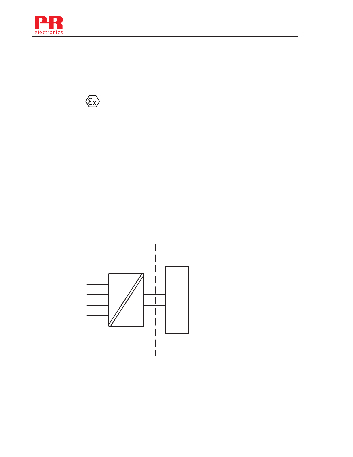
44 7501V107-UK
7501QA01
LERBAKKEN 10, 8410 RØNDE DENMARK. WWW.PRELECTRONICS.COM
Revision date:
2015-11-03
Version Revision
V2R0
Page:
3/6
Ex nA, ic installation:
Certificate
DEKRA15ATEX0058X
Marking II 3 G Ex nA IIC T6…T4 Gc
II 3 G Ex ic IIC T6...T4 Gc
II 3 D Ex ic IIIC T100°C Dc
Standards: EN 60079-0:2012, EN 60079-11:2012, EN60079-15:2010
Sensor
Terminal: 3,4,5,6
Ex ic
Uo: 9.6 VDC
Io: 28 mA
Po: 67 mW
Lo: 45 mH
Co: 28 μF
Supply
Terminal: 1,2
Ex ic
Ui: 35 VDC
Li: 0 μH
Ci: 2 nF
Supply
Terminal: 1,2
Ex nA
U : 35 VDC
1
2
6
5
4
3
+
-
Supply
7501
Hazardous area
Zone 2, 22
Non Hazardous Area
Type of protection Ex nA
O-ring Sealing : Silicone
T4: -40 ≤ Ta ≤ 85ºC T4 (7501A )
T4: -40 ≤ Ta ≤ 80ºC T4 (7501B )
T6: -40 ≤ Ta ≤ 60ºC T6
O-ring Sealing : FKM
T4: -20 ≤ Ta ≤ 85ºC (7501A )
T4: -20 ≤ Ta ≤ 80ºC (7501B )
T6: -20 ≤ Ta ≤ 60ºC
Type of protection Ex ic
T4: -40 ≤ Ta ≤ 85ºC T100ºC (7501A )
T4; -40 ≤ Ta ≤ 80ºC T100ºC (7501B )
T6: -40 ≤ Ta ≤ 60ºC T85 ºC
Page 45

7501V107-UK 45
7501QA01
LERBAKKEN 10, 8410 RØNDE DENMARK. WWW.PRELECTRONICS.COM
Revision date:
2015-11-03
Version Revision
V2R0
Page:
4/6
Ex nA, ic installation:
For an ambient temperature exceeding 70 °C, heat resistant cables and cable glands suitable for at
least 90°C shall be used.
If the transmitter is physically connected to a possible source of heating or cooling, e.g. by
mounting to a process pipe or a temperature sensor, the temperature at the point of connection
shall be within the ambient temperature range as given in the certificate.
Cable entries and blanking elements shall be used that are suitable for the application and correctly
installed.
The enclosure must be connected to the potential matching line
Applied screw terminal torque is max 0.4 Nm on all terminals.
Protection degree of IP 54 according to EN 60529 is achieved if certified cable glands or conduit
entry devices are used that are suitable for the application and correctly installed.
Protection degree of IP 68 according to EN 60529 is only achieved if certified cable glands or
conduit entry devices are used that are suitable for the application and correctly installed with
sealing washers or Loctite sealant added to the threads of the sensor, blanking elements and cable
glands.
For group III (dust), electrostatic charging of the paint layer shall be avoided
Page 46
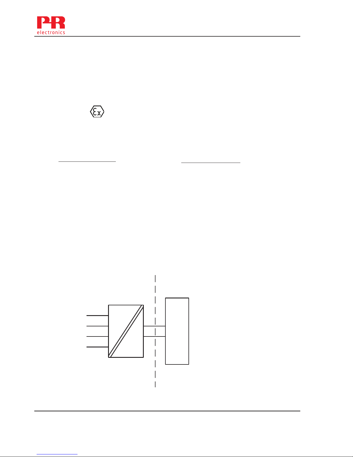
46 7501V107-UK
7501QA01
LERBAKKEN 10, 8410 RØNDE DENMARK. WWW.PRELECTRONICS.COM
Revision date:
2015-11-03
Version Revision
V2R0
Page:
5/6
Ex d, tb installation:
ATEX Certificate
DEKRA15ATEX0058X
Marking
Standards: EN 60079-0:2012, EN 60079-1:2007, EN60079-31:2014
Non Hazardous Area
Hazardous area
Zone 1, 2, 21, 22
II 2 G Ex d IIC T6…T4 Gb
II 2 D Ex tb IIIC T100°C Db
Terminal: 3,4,5,6
Sensor: RTD or TC
Terminal: 1,2
Umax: 35 VDC
1
2
6
5
4
3
+
-
Supply
7501
Type of protection Ex d
T4,T5: -40 ≤ Ta ≤ 85ºC (7501A )
T4,T5: -40 ≤ Ta ≤ 80ºC (7501B )
T6: -40 ≤ Ta ≤ 70ºC
Type of protection Ex tb
O-ring Sealing : Silicone
-40 ≤ Ta ≤ 85ºC T100°C (7501A )
-40 ≤ Ta ≤ 80ºC T100°C (7501B )
-40 ≤ Ta ≤ 70ºC T85°C
O-ring Sealing : FKM
-20 ≤ Ta ≤ 85ºC T100°C (7501A )
-20 ≤ Ta ≤ 80ºC T100°C (7501B )
-20 ≤ Ta ≤ 70ºC T85°C
Page 47

7501V107-UK 47
7501QA01
LERBAKKEN 10, 8410 RØNDE DENMARK. WWW.PRELECTRONICS.COM
Revision date:
2015-11-03
Version Revision
V2R0
Page:
6/6
Ex d, tb installation:
The transmitter is intended, either to be connected via a cable, or to be mounted directly onto a
temperature sensing probe.
Only ATEX/IECEx equipment certified sensors, suitable for the application and correctly installed,
may be mounted directly onto the Transmitter without additional certification of the combination.
If the transmitter is physically connected to a possible source of heating or cooling, e.g. by mounting
to a process pipe or a temperature sensor, the temperature at the point of connection shall be within
the ambient temperature range as given in the certificate. The sensor shall be suitable for use as
entry device on an Ex d enclosure and shall not add volume to the 7501 enclosure. The thread of the
sensor must be in compliance with EN60079-1 / EN60079-31.
Unused cable entries must be sealed by the blanking elements 8550-xxx and 8551-xxx supplied with
the 7501 or other Ex d and/or Ex tb certified blanking elements suitable for the application. .
Only Ex d and/or Ex tb certified cable and cable glands shall be used that are suitable for the
application and correctly installed.
Protection degree of IP 54 according to EN 60529 is achieved if Ex d certified cable glands or
conduit entry devices are used that are suitable for the application and correctly installed.
Protection degree of IP 68 according to EN 60529 is only achieved if Ex d certified cable glands or
conduit entry devices are used that are suitable for the application and correctly installed with sealing
washers or Loctite sealant added to the threads of the sensor, blanking elements and cable glands.
The display cover must be screwed all the way in and the safety catch must be fastened before
putting into service. Do not open display cover until 30 minutes after disconnecting power to the
equipment allowing internal capacitors to discharge, or do not open display cover unless area is
known to be safe
For an ambient temperature exceeding 70 °C, heat resistant cables and cable glands suitable for at
least 90°C shall be used.
The enclosure must be connected to the potential matching line.
When the process temperature range exceeds the service temperature range it shall be verified by
on-site temperature measurements, taking the worst case conditions into account, that the service
temperature does not exceed the range of the module.
For group III (dust), electrostatic charging of the paint layer shall be avoided
No modification to the enclosure is allowed by the customer except as mentioned in the manual or
installation drawing.
Page 48
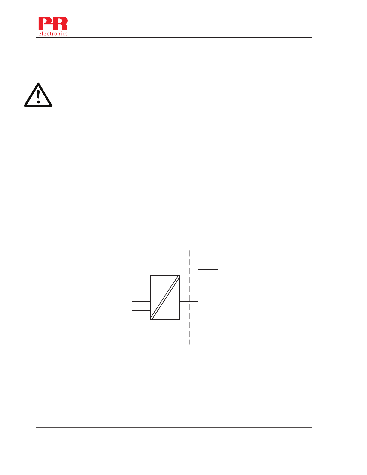
7501QI01
LERBAKKEN 10, 8410 RØNDE DENMARK. WWW.PRELECTRONICS.COM
Revision date:
2015-09-16
Version Revision
V2R0
Page:
1/6
7501 IECEx Installation
For safe installation of 7501 the following must be observed. The module shall only be installed by
qualified personnel who are familiar with the national and international laws, directives and
standards (IEC60079-14) that apply to this area.
Year of manufacture can be taken from the first two digits in the serial number.
Ex ia installation:
Certificate IECEx DEK 15.0039 X
Marking
Standards: IEC 60079-0: 2011, IEC 60079-11: 2011, IEC 60079-26: 2007
Hazardous area
Zone 0, 1, 2, 20, 21, 22, Mines
Non Hazardous Area
T4: -40 ≤ Ta ≤ 85ºC T100 ºC ( 7501A)
T4: -40 ≤ Ta ≤ 80ºC T100 ºC ( 7501B)
T5: -40 ≤ Ta ≤ 60ºC T75 ºC
T6: -40 ≤ Ta ≤ 45ºC T60 ºC
Ex ia IIC T6...T4 Ga
Ex ia IIIC T100°C Da
Ex ia I Ma (7501B )
Sensor
Terminal: 3,4,5,6
Uo: 9.6 VDC
Io: 28 mA
Po: 67 mW
Lo: 35 mH
Co: 3.5 μF
Supply
Terminal: 1,2
Ui: 30 VDC
Ii: 120 mA
Pi: 0.84 W
Li: 0 μH
Ci: 2 nF
1
2
6
5
4
3
+
-
Barrier
7501
48 7501V107-UK
Page 49

7501QI01
LERBAKKEN 10, 8410 RØNDE DENMARK. WWW.PRELECTRONICS.COM
Revision date:
2015-09-16
Version Revision
V2R0
Page:
2/6
Ex ia installation
General installation instructions
The sensor circuit is not infallibly galvanic isolated from the supply output circuit. However, the
galvanic isolation between the circuits is capable of withstanding a test voltage of 500Vac during 1
minute.
The enclosure must be connected to the potential matching line.
If the transmitter is physically connected to a possible source of heating or cooling, e.g. by
mounting to a process pipe or a temperature sensor, the temperature at the point of connection
shall be within the ambient temperature range as given in the certificate or in this manual.
Cable entries and blanking elements shall be used that are suitable for the application and correctly
installed.
For installalation of 7501A in zone 0 / EPL Ga, the transmitter must be installed such, that even in
the event of rare incidents, ignition sources due to impact and friction, sparks are excluded.
Protection degree of IP 54 according to IEC 60529 is achieved if certified cable glands or conduit
entry devices are used that are suitable for the application and correctly installed.
Protection degree of IP 68 according to IEC 60529 is only achieved if certified cable glands or
conduit entry devices are used that are suitable for the application and correctly installed with
sealing washers or Loctite sealant added to the threads of the sensor, blanking elements and cable
glands.
For group III (dust), electrostatic charging of the paint layer shall be avoided.
7501V107-UK 49
Page 50
7501QI01
LERBAKKEN 10, 8410 RØNDE DENMARK. WWW.PRELECTRONICS.COM
Revision date:
2015-09-16
Version Revision
V2R0
Page:
3/6
Ex nA, ic installation:
Certificate IECEx DEK 15.0039 X
Marking Ex nA IIC T6…T4 Gc
Ex ic IIC T6…T4 Gc
Ex ic IIIC T100°C Dc
Standards: IEC 60079-0: 2011, IEC 60079-11: 2011, IEC 60079-15: 2010
Sensor
Terminal: 3,4,5,6
Ex ic
Uo: 9.6 VDC
Io: 28 mA
Po: 67 mW
Lo: 45 mH
Co: 28 μF
Supply
Terminal: 1,2
Ex ic
Ui: 35 VDC
Li: 0 μH
Ci: 2 nF
Supply
Terminal: 1,2
Ex nA
Umax : 35 VDC
1
2
6
5
4
3
+
-
Supply
7501
Hazardous area
Zone 2, 22
Non Hazardous Area
Type of protection Ex nA
O-ring Sealing : Silicone
T4: -40 ≤ Ta ≤ 85ºC T4 (7501A )
T4: -40 ≤ Ta ≤ 80ºC T4 (7501B )
T6: -40 ≤ Ta ≤ 60ºC T6
O-ring Sealing : FKM
T4: -20 ≤ Ta ≤ 85ºC (7501A )
T4: -20 ≤ Ta ≤ 80ºC (7501B )
T6: -20 ≤ Ta ≤ 60ºC
Type of protection Ex ic
T4: -40 ≤ Ta ≤ 85ºC T100ºC (7501A )
T4; -40 ≤ Ta ≤ 80ºC T100ºC (7501B )
T6: -40 ≤ Ta ≤ 60ºC T85 ºC
50 7501V107-UK
Page 51

7501QI01
LERBAKKEN 10, 8410 RØNDE DENMARK. WWW.PRELECTRONICS.COM
Revision date:
2015-09-16
Version Revision
V2R0
Page:
4/6
Ex nA, ic installation:
For an ambient temperature exceeding 70°C, heat resistant cables and cable glands suitable for at
least 90°C shall be used.
If the transmitter is physically connected to a possible source of heating or cooling, e.g. by
mounting to a process pipe or a temperature sensor, the temperature at the point of connection
shall be within the ambient temperature range as given in the certificate.
Cable entries and blanking elements shall be used that are suitable for the application and correctly
installed.
The enclosure must be connected to the potential matching line
Applied screw terminal torque is max 0.4 Nm on all terminals.
Protection degree of IP 54 according to EN 60529 is achieved if certified cable glands or conduit
entry devices are used that are suitable for the application and correctly installed.
Protection degree of IP 68 according to EN 60529 is only achieved if certified cable glands or
conduit entry devices are used that are suitable for the application and correctly installed with
sealing washers or Loctite sealant added to the threads of the sensor, blanking elements and cable
glands.
For group III (dust), electrostatic charging of the paint layer shall be avoided
7501V107-UK 51
Page 52
7501QI01
LERBAKKEN 10, 8410 RØNDE DENMARK. WWW.PRELECTRONICS.COM
Revision date:
2015-09-16
Version Revision
V2R0
Page:
5/6
Ex d, tb installation:
Certificate IEC DEK 15.0039 X
Marking
Standards:IEC 60079-0: 2011, IEC 60079-1: 2007, IEC 60079-31: 2013
Non Hazardous Area
Hazardous area
Zone 1, 2, 21, 22
Ex d IIC T6…T4 Gb
Ex tb IIIC T100°C Db
Terminal: 3,4,5,6
Sensor: RTD or TC
Terminal: 1,2
Umax: 35 VDC
Type of protection Ex tb
O-ring Sealing : Silicone
-40 ≤ Ta ≤ 85ºC T100°C (7501A )
-40 ≤ Ta ≤ 80ºC T100°C (7501B )
-40 ≤ Ta ≤ 70ºC T85°C
O-ring Sealing : FKM
-20 ≤ Ta ≤ 85ºC T100°C (7501A )
-20 ≤ Ta ≤ 80ºC T100°C (7501B )
-20 ≤ Ta ≤ 70ºC T85°C
1
2
6
5
4
3
+
-
Supply
7501
Type of protection Ex d
T4,T5: -40 ≤ Ta ≤ 85ºC (7501A )
T4,T5: -40 ≤ Ta ≤ 80ºC (7501B )
T6: -40 ≤ Ta ≤ 70ºC
52 7501V107-UK
Page 53

7501QI01
LERBAKKEN 10, 8410 RØNDE DENMARK. WWW.PRELECTRONICS.COM
Revision date:
2015-09-16
Version Revision
V2R0
Page:
6/6
Ex d, tb installation
The transmitter is intended, either to be connected via a cable, or to be mounted directly onto a temperature
sensing probe.
Only IECEx equipment certified sensors, suitable for the application and correctly installed, may be mounted
directly onto the Transmitter without additional certification of the combination.
If the transmitter is physically connected to a possible source of heating or cooling, e.g. by mounting to a
process pipe or a temperature sensor, the temperature at the point of connection shall be within the ambient
temperature range as given in the certificate. The sensor shall be suitable for use as entry device on an Ex d
enclosure and shall not add volume to the 7501 enclosure. The thread of the sensor must be in compliance
with IEC60079-1/IEC60079-31
Unused cable entries must be sealed by the blanking elements 8550-xxx and 8551-xxx supplied with the
7501 or other Ex d and/or Ex tb certified blanking elements suitable for the application.
Only Ex d and/or Ex tb certified cable and cable glands shall be used that are suitable for the application and
correctly installed.
Protection degree of IP 54 according to IEC 60529 is achieved if Ex d certified cable glands or conduit entry
devices are used that are suitable for the application and correctly installed.
Protection degree of IP 68 according to IEC 60529 is only achieved if Ex d certified cable glands or conduit
entry devices are used that are suitable for the application and correctly installed with sealing washers or
Loctite sealant added to the threads of the sensor, blanking elements and cable glands.
The display cover must be screwed all the way in and the safety catch must be fastened before putting into
service. Do not open display cover until 30 minutes after disconnecting power to the equipment allowing
internal capacitors to discharge, or do not open display cover unless area is known to be safe
For an ambient temperature exceeding 70 °C, heat resistant cables and cable glands suitable for at least
90°C shall be used.
The enclosure must be connected to the potential matching line.
When the process temperature range exceeds the service temperature range it shall be verified by on-site
temperature measurements, taking the worst case conditions into account, that the service temperature does
not exceed the range of the module.
For group III (dust), electrostatic charging of the paint layer shall be avoided
No modification to the enclosure is allowed by the customer except as mentioned in the manual or
installation drawing.
7501V107-UK 53
Page 54

7501QF01
LERBAKKEN 10, 8410 RØNDE DENMARK. WWW.PRELECTRONICS.COM
Revision date:
2016-08-03
Version Revision
V5R0
Page:
1/5
FM Installation drawing 7501
For safe installation of 7501 the following must be observed. The module shall only be installed
by qualified personnel who are familiar with the national and international laws, directives and
standards that apply to this area.
Pour une mise en œuvre du 7501 en toute sécurité, les préconisations ci-dessous doivent être
observées. Le module doit être mis en œuvre par du personnel qualifié familier avec les Lois,
Directives et Normes, nationales et internationales, qui s’appliquent à la zone d’installation.
Intrinsic safe installation:
Hazardous classified Location
Class I,II,II Division1 Groups, ABCDEFG
Class I, Zone 0, IIC, Zone 20
T4: -40 ≤ Ta ≤ 85ºC
T5: -40 ≤ Ta ≤ 60ºC
T6: -40 ≤ Ta ≤ 40ºC
Zone 20 Temperature Class:
-40 ≤ Ta ≤ 85ºC T100 ºC
-40 ≤ Ta ≤ 60ºC T75 ºC
-40 ≤ Ta ≤ 40ºC T60 ºC
Non classified Location
Terminal: 3,4,5,6
Uo: 9.6 VDC
Io: 28 mA
Po: 67 mW
Lo: 35 mH
Co: 3.5 μF
Terminal: 1,2
Ui: 30 VDC
Ii: 120 mA
Pi: 0.84 W
Li: 0 μH
Ci: 2 nF
UM < 250V
Voc or Uo < Vmax or Ui
Isc or Io < Imax or Ii
Po < Pi
Ca or Co > Ci + Ccable
La or Lo > Li + Lcable
The barrier must not
be connected to any
associated apparatus
which uses or
generates more than
250 VRMS
1
2
6
5
4
3
+
-
Barrier
7501
54 7501V107-UK
Page 55

7501QF01
LERBAKKEN 10, 8410 RØNDE DENMARK. WWW.PRELECTRONICS.COM
Revision date:
2016-08-03
Version Revision
V5R0
Page:
2/5
The entity concept
The Transmitter must be installed according to National Electrical Code (ANSI-NFPA 70) and shall be
installed with the enclosure, mounting, and spacing segregation requirement of the ultimate application.
Equipment that is FM-approved for intrinsic safety may be connected to barriers based on the ENTITY
CONCEPT. This concept permits interconnection of approved transmitters, meters and other devices in
combinations which have not been specifically examined by FM, provided that the agency's criteria are
met. The combination is then intrinsically safe, if the entity concept is acceptable to the authority having
jurisdiction over the installation.
The entity concept criteria are as follows:
ices, other than barriers, must not be a source of power.
The maximum voltage Ui(V
MAX
) and current Ii(I
MAX
), and maximum power Pi(Pmax), which the device can
receive and remain intrinsically safe, must be equal to or greater than the voltage (Uo or V
OC
or Vt) and
current (Io or I
SC
or It) and the power Po which can be delivered by the barrier.
The sum of the maximum unprotected capacitance (C
i
) for each intrinsically device and the interconnect-
ing wiring must be less than the capacitance (C
a
) which can be safely connected to the barrier.
The sum of the maximum unprotected inductance (L
i
) for each intrinsically device and the interconnecting
wiring must be less than the inductance (L
a
) which can be safely connected to the barrier.
The entity parameters Uo,V
OC
or Vt and Io,ISC or It, and Ca and La for barriers are provided by the barrier
manufacturer.
For Class II and Class III installations where rigid conduit is not used, seal cable entries against dust and
fibres using a NRTL listed cable gland fitting.
7501V107-UK 55
Page 56
7501QF01
LERBAKKEN 10, 8410 RØNDE DENMARK. WWW.PRELECTRONICS.COM
Revision date:
2016-08-03
Version Revision
V5R0
Page:
3/5
Non Incendive installation:
Hazardous classified Location
Class I,II,III ,Division 2, Groups, ABCDFG
Class I, Zone 2, IIC
Non classified Location
Terminal: 1,2
Vmax: 35 VDC
1
2
6
5
4
3
+
-
7501
Vmax
35V
T4: -20/-40 ≤ Ta ≤ 85ºC
T6: -20/-40 ≤ Ta ≤ 60ºC
Terminal: 3,4,5,6
Sensor: RTD or TC
O-ring Sealings
Silicone rubber:-40°C ≤Ta ≤ +85°C
FKM rubber: -20°C ≤Ta ≤ +85°C
Protection: Indoor and Outdoor TYPE 4X or IP66
56 7501V107-UK
Page 57
7501QF01
LERBAKKEN 10, 8410 RØNDE DENMARK. WWW.PRELECTRONICS.COM
Revision date:
2016-08-03
Version Revision
V5R0
Page:
4/5
Explosion proof / Dust ignition proof installation
1
2
6
5
4
3
+
-
Supply
7501
Hazardous area
Class I, II, III Division 1, Groups ABCDEFG
Class I Zone 1, Ex/AEx d IIC T6
Non Hazardous Area
Terminal: 1,2
Umax: 35 VDC
Terminal: 3,4,5,6
Sensor: RTD or TC
T6: -20 /-40 ≤ Ta ≤ 70ºC
T5, T4: -20 /-40 ≤ Ta ≤ 85ºC
O-ring Sealings
Silicone rubber:-40°C ≤Ta ≤ +85°C
FKM rubber: -20°C ≤Ta ≤ +85°C
Protection: Indoor and Outdoor Type 4X or IP66
7501V107-UK 57
Page 58

7501QF01
LERBAKKEN 10, 8410 RØNDE DENMARK. WWW.PRELECTRONICS.COM
Revision date:
2016-08-03
Version Revision
V5R0
Page:
5/5
Explosion proof / Dust ignition proof installation
The enclosure must be installed such, that even in the event of rare incidents, ignition sources due to impact
and friction, sparks are excluded.
Unused cable entries must be sealed by approved sealing plugs.
Certified cable and cable glands shall be used that are suitable for the application and correctly installed or
the cables must be run in conduit.
For an ambient temperature exceeding 70 °C, heat resistant cables and cable glands suitable for at least
90°C shall be used.
For process temperatures above 85°C or below -20/-40°C installer must verify by measurements that the
service temperature of the 7501 module is held within this range taking worst conditions into account.
The display cover must be screwed all the way in and the safety catch must be fastened before operation.
Protection degree of IP 66 or TYPE4X is only achieved if certified cable glands or conduit entry devices are
used that are suitable for the application and correctly installed with sealing washers or Loctite sealant is
added to the threads of the sensor, blanking elements and cable glands.
The enclosure must be connected to the potential matching line.
Warning.
Do not open display cover unless area is known to be safe.
For installation in Canada the following must be taken into account:
All openings for conduit and sensor connection must be in NPT threads.
For Class I Group A installation, conduit seal is required within 18 inches of the enclosure.
For Class I Zone I installation, conduit seal is required within 18 inches of the enclosure.
Attention.
Ne pas ouvrir le couvercle de l’afficheur tant que la zone n’est pas réputée non explosible.
Pour une mise en œuvre au Canada, les préconisations ci-dessous doivent être observées :
Toutes les ouvertures d’entrée process et connexion de capteur doivent être munies de filetage
NPT.
Pour une mise en œuvre en Classe I, Groupe A, des joints d’étanchéité doivent être mises en
place à moins de 18 pouces du boîtier.
Pour une mise en œuvre en Classe I, Zone I, des joints d’étanchéité doivent être mises en place à
moins de 18 pouces du boîtier.
58 7501V107-UK
Page 59
7501QC01
LERBAKKEN 10, 8410 RØNDE DENMARK. WWW.PRELECTRONICS.COM
Revision date:
2015-11-03
Version Revision
V3R0
Page:
1/3
7501 CSA Installation
For safe installation of 7501 the following must be observed. The module shall only be installed by
qualified personnel who are familiar with the national and international laws, directives and
standards that apply to this area.
Intrinsic Safe Installation / SÉCURITÉ INTRINSÉQUE , Exia
Applicable for ( 7501A…. and 7501B….).
Hazardous classified Location
Class I,Division1, Groups, ABCD;
Class II,Group EFG;
Class III, Division 1.
Class I, Zone 0, IIC
Ex/AEx ia IIC Ga
Substitution of components may impair intrinsic safety.
AVERTISSEMENT
LA SUBSTITUTION DE COMPOSANTS PEUT COMPROMETTRE LA SÉCURITÉ INTRINSÉQUE
es stipulated in the Canadian
Electrical Code (CEC) or for US the National Electrical Code (NEC).
Non classified Location
Terminal: 3,4,5,6
Uo: 9.6 VDC
Io: 28 mA
Po: 67 mW
Lo: 35 mH
Co: 3.5 μF
Terminal: 1,2
Ui: 30 VDC
Ii: 120 mA
Pi: 0.84 W
Li: 0 μH
Ci: 2 nF
UM < 250V
Voc or Uo < Vmax or Ui
Isc or Io < Imax or Ii
Po < Pi
Ca or Co > Ci + Ccable
La or Lo > Li + Lcable
The barrier must not
be connected to any
associated apparatus
which uses or
generates more than
250 VRMS
T4: -40 ≤ Ta ≤ 85ºC T100 ºC (7501A)
T4: -40 ≤ Ta ≤ 80ºC T100 ºC (7501B)
T5: -40 ≤ Ta ≤ 60ºC T75 ºC
T6: -40 ≤ Ta ≤ 45ºC T60 ºC
1
2
6
5
4
3
+
-
Barrier
7501
7501V107-UK 59
Page 60
7501QC01
LERBAKKEN 10, 8410 RØNDE DENMARK. WWW.PRELECTRONICS.COM
Revision date:
2015-11-03
Version Revision
V3R0
Page:
2/3
Explosion proof / Dust ignition proof installation:
Applicable for ( 7501A )
Explosion proof for Hazardous area
Class I, Division 1, Groups ABCD;
Class II, Division 1, Groups EFG;
Class III
Ex d IIC, Class I, Zone 1
T4,T5: -20/-40 ≤ Ta ≤ 85ºC T100°C
T6: -20/-40 ≤ Ta ≤ 70ºC T85°C
Non Hazardous Area
1
2
6
5
4
3
+
-
Supply
7501
Terminal: 1,2
Umax: 35 VDC
Terminal: 3,4,5,6
Sensor: RTD or TC
O-ring Sealing
Silicone rubber:-40°C ≤Ta ≤ +85°C
FKM rubber: -20°C ≤Ta ≤ +85°C
60 7501V107-UK
Page 61

7501QC01
LERBAKKEN 10, 8410 RØNDE DENMARK. WWW.PRELECTRONICS.COM
Revision date:
2015-11-03
Version Revision
V3R0
Page:
3/3
Explosion proof / Dust ignition proof installation:
Applicable for ( 7501A )
Conduit and sensor connections must be in NPT modified threads.
Only third party certified sensors suitable for Class I, Division 1, Groups ABCDEFG or
Class I ,Zone 1 IIC may be attached to the Temperature Transmitter without additional approval
of the combination.
For Class I Group A installation and Class I Zone 1 installation, conduit seal is required within 18
inches of enclosure.
For an ambient temperature exceeding 70°C, heat resistant cables and cables suitable for at least
90°C shall be used.
The display cover must be screwed all the way in and the safety catch must be fastened before
putting the module into service.
Do not open / remove front cover unless area is known to be safe.
The remote temperature sensor must comply with the requirements for installation in hazardous
locations “Class I, Division 1 / Zone 1, Groups ABCD / IIC”
The remote temperature sensor must comply with the requirements for Ex d installation
Only certified cable and cable glands shall be used that are suitable for the application and
correctly installed.
For protection according to Type 4X / IP66 use Loctite 577 on threads of sensor and cable glands.
The enclosure must be connected to the potential matching line
Unused cable entries must be sealed by the blanking elements supplied with the 7501 or other Ex
certified blanking elements.
If the transmitter is physically connected to a possible source of heating or cooling, e.g. by
mounting to a process pipe or a temperature sensor, the temperature at the point of connection
shall be within the ambient temperature range as given in the certificate.
When the process temperature range exceeds the service temperature range it shall be verified by
on-site temperature measurements, taking the worst case conditions into account, that the service
temperature does not exceed the range of the module.
For Class II, III, electrostatic charging of the paint layer shall be avoided.
No modification to the enclosure is allowed by the customer except as mentioned in the manual or
installation drawing.
7501V107-UK 61
Page 62
7501QB01
LERBAKKEN 10, 8410 RØNDE DENMARK. WWW.PRELECTRONICS.COM
Revision date:
2015-11-04
Version Revision
V2R0
Page:
1/6
7501 Desenho de Instalação INMETRO
Para instalação segura do 7501 o seguinte deve ser observado. O módulo deve ser instalado,
apenas por pessoas qualificadas as quais estão familiarizadas com as normas nacionais e
internacionais, diretrizes e padrões (ABNT NBR IEC60079-14) que se aplicam a esta área.
Instalação Segura do Ex ia installation:
Certificado DEKRA 15.0014X
Marca
Normas : ABNT NBR IEC 60079-0: 2013, ABNT NBR IEC 60079-11: 2013
ABNT NBR IEC 60079-26: 2008
Áreas não classificadas
Áreas classificadas
Zona 0, 1, 2, 20, 21, 22, Minas
T4: -40 ≤ Ta ≤ 85ºC T100 ºC (7501A)
T4: -40 ≤ Ta ≤ 80ºC T100 ºC (7501B)
T5: -40 ≤ Ta ≤ 60ºC T100 ºC
T6: -40 ≤ Ta ≤ 45ºC T100 ºC
Ex ia IIC T6...T4 Ga
Ex ia IIIC T100°C Da
Ex ia I Ma (apenas para Tipo 7501B.....2. )
Terminal do
sensor: 3,4,5,6
Uo: 9.6 VDC
Io: 28 mA
Po: 67 mW
Lo: 35 mH
Co: 3.5 μF
Terminal de
alimentação: 1,2
Ui: 30 VDC
Ii: 120 mA
Pi: 0.84 W
Li: 0 μH
Ci: 2 nF
1
2
6
5
4
3
+
-
Barrier
7501
62 7501V107-UK
Page 63

7501QB01
LERBAKKEN 10, 8410 RØNDE DENMARK. WWW.PRELECTRONICS.COM
Revision date:
2015-11-04
Version Revision
V2R0
Page:
2/6
Instalação do Ex ia
Instruções de instalação gerais
O circuito do sensor não é infalivelmente galvânico-isolado do circuito de saída de alimentação.
Contudo, a isolação galvânica entre os circuitos é capaz de resistir a teste de tensão de 500Vac
durante 1 minuto.
O equipamento deve ser conectado à linha potencial correspondente
Se o transmissor estiver fisicamente conectado a uma possível fonte de calor ou resfriamento, por
exemplo, através da montagem de um tubo de processo ou sensor de temperatura, a temperatura
no ponto de conexão deve estar entre a faixa de temperatura ambiente determinada no certificado
ou neste manual.
As entradas dos cabos e elementos de supressão devem ser usadas adequadamente para
aplicação INMETRO, aprovada e instalada corretamente.
Para instalação 7501A em zona 0 / EPL Ga, se aplicam as seguintes instruções:
O transmissor deve ser instalado de modo que, mesmo em um evento raro de incidente, fontes de
ignição devido a impactos e fricção, faíscas sejam evitadas.
O grau de proteção do IP 54 de acordo com a ABNT NBR IEC 60529 é alcançado se o certificado
prensa-cabos ou dispositivos de entrada de conduíte são usados e adequados para a aplicação e
instalados corretamente.
O grau de proteção do IP 68 de acordo com a ABNT NBR IEC 60529 é apenas alcançado se o
certificado prensa-cabos ou dispositivos de entrada de conduíte são usados e adequados para
aplicação e instalados corretamente com selos de vedação ou selante Loctite adicionados para as
linhas do sensor, elementos de supressão e prensa-cabos.
Para o grupo III (poeiras), deve ser evitada a carga electrostática da camada de tinta.
7501V107-UK 63
Page 64
7501QB01
LERBAKKEN 10, 8410 RØNDE DENMARK. WWW.PRELECTRONICS.COM
Revision date:
2015-11-04
Version Revision
V2R0
Page:
3/6
Instalação Ex ic, Ex nA:
Certificado DEKRA 15.0014X
Marca Ex nA IIC T6…T4 Gc
Ex ic IIC T6…T4 Gc
Normas: ABNT NBR IEC 60079-0: 2013, ABNT NBR IEC 60079-15: 2012
Terminal do
sensor: 3,4,5,6
Ex ic
Uo: 9.6 VDC
Io: 28 mA
Po: 67 mW
Lo: 45 mH
Co: 28 μF
Terminal de
alimentação: 1,2
Ex ic
Ui: 35 VDC
Li: 0 μH
Ci: 2 nF
Terminal de
alimentação: 1,2
Ex nA
U : 35 VDC
1
2
6
5
4
3
+
-
Supply
7501
Áreas classificadas
Zona 2
Áreas não classificadas
Ex nA
Anel de vedação O : Silicone
T4: -40 ≤ Ta ≤ 85ºC (7501A )
T4: -40 ≤ Ta ≤ 80ºC (7501B )
T6: -40 ≤ Ta ≤ 60ºC
Anel de vedação O : FKM
T4: -20 ≤ Ta ≤ 85ºC (7501A )
T4: -20 ≤ Ta ≤ 80ºC (7501B )
T6: -20 ≤ Ta ≤ 60ºC
Ex ic
T4: -40 ≤ Ta ≤ 85ºC (7501A )
T4; -40 ≤ Ta ≤ 80ºC (7501B )
T6: -40 ≤ Ta ≤ 60ºC
64 7501V107-UK
Page 65

7501QB01
LERBAKKEN 10, 8410 RØNDE DENMARK. WWW.PRELECTRONICS.COM
Revision date:
2015-11-04
Version Revision
V2R0
Page:
4/6
Instalação Ex ic, Ex nA:
Para uma temperatura ambiente excedendo 70 ºC, cabos resistentes ao calor e prensa-cabos
adequados para pelo menos 90 ºC devem ser usados.
Se o transmissor estiver fisicamente conectado a uma possível fonte de calor ou resfriamento, por
exemplo, através da montagem de um tubo de processo ou sensor de temperatura, a temperatura
no ponto de conexão deve estar entre a faixa de temperatura ambiente determinada no certificado
ou neste manual.
As entradas dos cabos e elementos de supressão devem ser usadas adequadamente para a
aplicação e instaladas corretamente.
O equipamento deve ser conectado à linha potencial correspondente
O torque aplicado no terminal de parafusos é no máximo 0.4 Nm em todos os terminais.
O grau de proteção do IP 54 de acordo com a ABNT NBR IEC 60529 é alcançado se o certificado
prensa-cabos ou dispositivos de entrada de conduíte são usados e adequados para a aplicação e
instalados corretamente.
O grau de proteção do IP 68 de acordo com a ABNT NBR IEC 60529 é apenas alcançado se o
certificado prensa-cabos ou dispositivos de entrada de conduíte são usados e adequados para
aplicação e instalados corretamente com selos de vedação ou selante Loctite adicionados para as
linhas do sensor, elementos de supressão e prensa-cabos.
7501V107-UK 65
Page 66
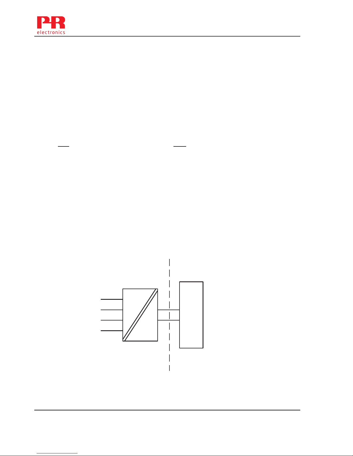
7501QB01
LERBAKKEN 10, 8410 RØNDE DENMARK. WWW.PRELECTRONICS.COM
Revision date:
2015-11-04
Version Revision
V2R0
Page:
5/6
Instalação Ex tb, Ex d:
Certificado DEKRA 15.0014X
Marca
Normas ABNT NBR IEC 60079-0: 2013, ABNT NBR IEC 60079-1: 2009,
ABNT NBR IEC 60079-31:2014
Áreas não classificadas
Áreas classificadas
Zona 1, 2, 21, 22
Ex d IIC T6…T4 Gb
Ex tb IIIC T100°C Db
Terminal: 3,4,5,6
Sensor: RTD ou TC
Terminal: 1,2
Alimentação: 35 VDC
1
2
6
5
4
3
+
-
Supply
7501
Ex d
T4,T5: -40 ≤ Ta ≤ 85ºC (7501A )
T4,T5: -40 ≤ Ta ≤ 80ºC (7501B )
T6: -40 ≤ Ta ≤ 70ºC
Ex tb
Anel de vedação O: Silicone
-40 ≤ Ta ≤ 85ºC T100°C (7501A )
-40 ≤ Ta ≤ 80ºC T100°C (7501B )
-40 ≤ Ta ≤ 70ºC T100°C
Anel de vedação O: FKM
-20 ≤ Ta ≤ 85ºC T100°C (7501A )
-20 ≤ Ta ≤ 80ºC T100°C (7501B )
-20 ≤ Ta ≤ 70ºC T100°C
66 7501V107-UK
Page 67

7501QB01
LERBAKKEN 10, 8410 RØNDE DENMARK. WWW.PRELECTRONICS.COM
Revision date:
2015-11-04
Version Revision
V2R0
Page:
6/6
Instalação Ex tb, Ex d:
O transmissor é destinado, quer para ser ligado através de um cabo, ou pode ser montado directamente
sobre uma sonda de detecção de temperatura.
Sensores apenas INMETRO certificadas, apropriadas para a aplicação e instalado corretamente, pode ser
montado diretamente sobre o transmissor sem certificação adicional da combinação.
Se o transmissor estiver fisicamente conectado a uma possível fonte de calor ou resfriamento, por exemplo,
através da montagem de um tubo de processo ou sensor de temperatura, a temperatura no ponto de
conexão deve estar entre a faixa de temperatura ambiente dada no certificado. O sensor deve ser adequado
para ser usado como entrada de equipamento no equipamento Ex d e nenhum volume deve ser adicionado
no enclosure do 7501.
Entradas de cabos não utilizadas devem ser selados pelas elementos de bloqueio 8550-xxx e 8551-xxx
fornecidos com o 7501 ou seladas pelo INMETRO aprovou elementos adequados para a aplicação.
Prensa-cabos e cabos devem ser INMETRO Ex d / tb aprovado, adequado para a aplicação e
correctamente instalados
O Sensor / Sonda aplicado deve ser adequado para a aplicação, instalado corretamente, e deve ser
certificado pelo INMETRO.
O grau de proteção do IP 54 de acordo com a ABNT NBR IEC 60529 é alcançado se o certificado Ex de
prensa-cabos ou dispositivos de entrada de conduíte são usados e adequados para a aplicação e instalados
corretamente.
O grau de proteção do IP 68 de acordo com a ABNT NBR IEC 60529 é apenas alcançado se o certificado
Ex de prensa-cabos ou dispositivos de entrada de conduíte são usados e adequados para aplicação e
instalados corretamente com selos de vedação ou selante Loctite adicionados para as linhas do sensor,
elementos de supressão e prensa-cabos.
A tampa do display deve ser parafusada em todos os pontos e o fecho de segurança deve ser ajustado
antes de colocá-lo em serviço. Não abra a tampa do display até 30 minutos depois de desconectar a
alimentação a fim de permitir que os capacitores internos descarreguem, ou não abra a tampa do display a
menos que a área seja conhecida como segura.
Para uma temperatura ambiente que excede 70 ºC, cabos resistentes a aquecimento e prensa-cabos
adequados para pelo menos 90 ºC devem ser usados.
O equipamento deve ser conectado em uma linha potencial correspondente.
Quando a faixa de temperatura do processo excede a faixa de temperatura de serviço ela deve ser
verificada através de medições de temperatura no local, levando a pior condição em conta, que a
temperatura de serviço não exceda a faixa do módulo.
Para o grupo III (poeiras), deve ser evitada a carga electrostática da camada de tinta.
Nenhuma modificação no equipamento pelo cliente é permitida exceto o que é mencionado no manual ou no
desenho de instalação.
7501V107-UK 67
Page 68

68 7501V107-UK
Document history
The following list provides notes concerning revisions of this document.
Rev. ID Date Notes
100 1524 initial release of the product
101 1530 FM installation drawing updated
Application drawing updated
102 1541 CSA, EU-RO marine, InMetro and NEPSI approvals
added
103 1543 Assembly drawing added
104 1612 Installations drawings updated
2 items added under accessories
105 1634 New firmware - menu structure updated to enable
PIN code access to menus
106 1651 FM installation drawing updated
107 1719 Version with stainless steel housing added
Page 69

We are near you,
all over the world
All our devices are backed by expert service and a 5-year
warranty. With each product you purchase, you receive
personal technical support and guidance, day-to-day
delivery, repair without charge within the warranty period
and easily accessible documentation.
We are headquartered in Denmark, and have offices and
authorized partners the world over. We are a local
business with a global reach. This means that we are
always nearby and know your local markets well.
We are committed to your satisfaction and provide
PERFORMANCE MADE SMARTER all around the world.
For more information on our warranty program, or to
meet with a sales representative in your region, visit
prelectronics.com.
Our trusted red boxes are supported wherever you are
Page 70

PR electronics is the leading technology company specialized in making industrial process
control safer, more reliable and more efficient. Since 1974, we have been dedicated to
perfecting our core competence of innovating high precision technology with low power
consumption. This dedication continues to set new standards for products communicating,
monitoring and connecting our customers’ process measurement points to their process
control systems.
Our innovative, patented technologies are derived from our extensive R&D facilities and
from having a great understanding of our customers’ needs and processes. We are guided
by principles of simplicity, focus, courage and excellence, enabling some of the world’s
greatest companies to achieve PERFORMANCE MADE SMARTER.
Benefit today from
PERFORMANCE MADE SMARTER
www.prelectronics.com
 Loading...