

Page 1

5350
PROFIBUS® PA / FOUNDA TION™
Fieldbus Transmitter
No. 5350Q102(0420)
From ser. no. 030640001
Approvals
Configuration Manual
FOUNDA TION™ Fieldbus
Page 2

2
CONTENTS
Introduction ......................................................................... 4
This configuration manual......................................................... 4
The Fieldbus Software............................................................ 4
Parameter lists abbreviations...................................................... 4
1.0 The Resource Block, Fieldbus Foundation........................................... 5
1.1 Introduction .................................................................. 5
1.2 Description................................................................... 5
1.3 RESTART parameter........................................................... 5
1.4 Non-volatile parameters....................................................... 5
1.5 Timeout for remote cascade modes ............................................ 5
1.6 Alert Notification ............................................................. 5
1.7 FEATURES / FEATURE_SEL parameters ......................................... 6
1.8 Fault state for the whole resource ............................................. 6
1.9 Write lock by software ........................................................ 6
1.10 Features being implemented ................................................ 6
1.11 BLOCK_ERR ................................................................. 6
1.12 Supported Modes............................................................ 6
1.13 Resource Block Parameter List, Fieldbus Foundation ............................... 7
2.0 The Transducer Block ............................................................. 9
2.1 The Transducer Block ......................................................... 9
2.2 The data of the Transducer Block Parameter List are grouped as follows: ......... 9
2.3 Default configuration ......................................................... 9
2.4 Your application set up......................................................... 9
2.5 AI_Transducer Block Configuration Flowchart ....................................... 10
2.6 - Transducer Block Examples Setup ................................................ 13
2.6.1 Measurement of RTD with one sensor:........................................ 13
2.6.2 Measurement of RTD with two sensors: ...................................... 13
2.6.3 Measurement of thermocouple with one sensor: .............................. 13
2.6.4 Measurement of thermocouple with two sensors: ............................. 14
2.6.5 Measurement of combined sensors (Sensor 1 = TC and Sensor 2 = RTD): ........ 14
2.6.6 Measurement of resistance (linear) with one sensor: .......................... 14
2.6.7 Measurement of resistance (linear) with two sensors: ......................... 15
2.6.8 Measurement of potentiometer (linear) with one sensor: ...................... 15
2.6.9 Measurement of potentiometer (linear) with two sensors: ..................... 15
2.6.10 Measurement of voltage (linear) with one sensor: ........................... 16
2.6.11 Measurement of voltage (linear) with two sensors: .......................... 16
2.6.12 Measurement of 2 potentiometers (with Linear interpolation linearisation): ... 16
2.6.13 Measurement of TC (with Custom Polynomial Linearisation) on sensor 1....... 17
2.7 AI_Transducer and PR_CUST_LIN Block, Schematic .................................. 18
2.8 AI_TRANSDUCER Block Parameter List ............................................. 19
2.8.1 Sensor characterising parameters ............................................ 19
2.8.2 RTD / Resistor specific parameters ........................................... 20
2.8.3 Thermocouple specific parameters ........................................... 20
2.8.4 Output conditioning parameters.............................................. 21
2.8.5 Output parameters.......................................................... 21
2.8.6 Diagnostic parameters ...................................................... 22
2.8.7 Sensor error detection parameters ........................................... 22
2.8.8 Sensor calibration, Description ............................................... 23
2.8.9 Sensor Calibration Parameters ............................................... 23
2.9 PR_CUST_LIN Block Parameter List ................................................ 25
2.9.1 Linear interpolation linearisation, Description ................................. 25
2.9.2 Linear Interpolation Linearisation, Parameter List. ............................ 25
Page 3

3
2.9.3 Custom polynomial linearisation, Description .................................. 26
2.9.4 Custom Polynomial Linearisation, Parameter List .............................. 27
2.10 PR_CUST_PRIV Block Reserved Parameter List .................................... 27
2.10.1 Description, PR_CUST_PRIV Block........................................... 27
3.0 Analogue Input Blocks ............................................................ 28
3.1 Analogue Input Blocks, Fieldbus Foundation ........................................ 28
3.2 Overview .................................................................... 28
3.3 Analogue Input Block Schematic ............................................... 28
3.4 Description .................................................................. 28
3.5 Supported Modes ............................................................. 29
3.6 To enable the Simulation mode ................................................ 29
3.7 Alarm Types .................................................................. 29
3.8 Mode Handling ............................................................... 29
3.9 Status Handling .............................................................. 29
3.10 Initialisation ................................................................ 29
3.11 Analogue Input Blocks Parameter List, Fieldbus Foundation ........................ 29
4.0 PID Control Block, Fieldbus Foundation ............................................. 31
4.1 Introduction: ................................................................. 31
4.2 Overview .................................................................... 31
4.3 Schematic: ................................................................... 31
4.4 Description................................................................... 31
4.5 Supported Modes ............................................................. 32
4.6 Alarm Types .................................................................. 32
4.7 Mode Handling ............................................................... 32
4.8 Status Handling .............................................................. 32
4.9 Initialization.................................................................. 32
4.10 PID Control Block Parameter List.................................................. 33
5.0 Link Active Scheduler (LAS) ....................................................... 36
5.1 Introduction: ................................................................. 36
5.2 Overview .................................................................... 36
5.3 Description................................................................... 36
Page 4

4
Introduction
This configuration manual
contains the necessary information for configuration of the temperature transmitter PR5350
via a host system with application software for either FoundationTM Fieldbus or Profibus® PA.
The autoswitch function of the modules ensures automatic switch to the connected protocol.
The Fieldbus Software
has been developped by PR electronics A/S according to the specifications of the Fieldbus
Foundation and the PROFIBUS Nutzerorganisation.
The files for Foundation
TM
Fieldbus are:
xxyy.o - Device Description binary file
xxyy.sym - Device Description symbol file
xxyyzz.c - Capability file
xx, yy and zz refer to the version numbers of the files.
PR electronics fieldbus transmitters are delivered with a CD that contains the files needed to
configure the transmitters from a fieldbus host. These files can also be downloaded from our
homepage www.prelectronics.com.
Please follow the instructions for the application software in question when installing the
files.
Parameter lists abbreviations
In the Store column:
SRC = Static Revision Counter; N = No; D = Dynamic;
Cst = Constant. The parameter doesn’t change in a device
In the RO / R/W column:
RO = Read Only; R /W = Read Write; * = Mixed of RO and R/W; ** = Don’t care
Page 5

5
1.0 The Resource Block, Fieldbus Foundation
1.1 Introduction
The resource block is used to define a hardware specific characteristics of the function block
applications. It provides PR’s manufacturer’s name, device name, DD and block status and hardware details. It also indicates how much resource (memory and CPU) is available and controls
the overall device.
1.2 Description
This block contains data that is specific to the hardware that is associated with the resource.
All data is modelled within a controlled space, so there are no outside inputs into this block required.
This parameter “set” is intended to be the minimum required for the Function Block Application
associated with the resource in which it resides. Some parameters that could be in the set, like
calibration data and ambient temperature, are more part of their respective transducer blocks.
The “mode” is used to control major states of the resource. O/S mode stops all function block
execution. The actual mode of the function blocks will be changed to O/S (out of service), but
the target mode will not be changed. Auto mode allows normal operation of the resource. IMan
shows that the resource is initializing or receiving a software download. Parameters MANUFAC_ID, DEV_TYPE, DEV_REV, DD_REV, and DD_RESOURCE are required to identify and locate
the DD so that Device Description Hosting Services can select the correct DD for use with
the resource. The parameter HARD_TYPES is a read only bit string that indicates the types of
hardware that are available to this resource. If an I/O block is configured that requires a type
of hardware that is not available, the result will be a block alarm for a configuration error. The
RS_STATE parameter contains the operational state of the Function Block Application for the
resource containing this resource block.
1.3 RESTART parameter
The RESTART parameter allows degrees of initialization of the resource. They are:
1 - Run: it is the passive state of the parameter
2 - Restart resource: it is intended to clear up problems for example the memory management
resource.
3 - Restart with defaults: it is intended to wipe configuration memory, it works like a factory
initialization.
4 - Restart processor: it provides a way to hit the reset button on the processor associated
with the resource This parameter does not appear in a view because it returns to 1 shortly after being written.
1.4 Non-volatile parameters
All non-volatile parameters are saved in EEPROM and therefore used if the device is restarted.
1.5 Timeout for remote cascade modes
SHED_RCAS and SHED_ROUT set the time limit for loss of communication from a remote device. These constants are used by all function blocks that support a remote cascade mode. The
eect of a timeout is described in Mode Calculation. Shedding from RCAS/ROUT shall not happen when SHED_RCAS or SHED_ROUT is set to zero.
1.6 Alert Notification
The MAX_NOTIFY parameter value is the maximum number of alert reports that this resource
can have sent without getting a confirmation, corresponding to the amount of buer space
available for alert messages. A user can set the number lower than that, to control alert flooding, by adjusting the LIM_NOTIFY parameter value. If LIM_NOTIFY is set to zero, then no alerts
are reported. The CONFIRM_TIME parameter is the time for the resource to wait for confirmation of receipt of a report before trying again. If the CONFIRM_TIME = 0 the device shall not
retry.
Page 6

6
1.7 FEATURES / FEATURE_SEL parameters
The bit strings FEATURES and FEATURE_SEL determine optional behaviour of the resource.
The first defines the available features, and is read only. The second is used to turn on an
available feature by configuration. If a bit is set in FEATURE_SEL that is not set in FEATURES,
the result will be a block alarm for a configuration error. The device supports the following features: Reports supported, Fault State supported, Soft Write lock supported.
1.8 Fault state for the whole resource
If the user sets the SET_FSTATE parameter, the FAULT_STATE parameter will indicate active
and it will cause all output function blocks in the resource to go immediately to the condition
chosen by the fault state Type I/O option. It may be cleared by setting the CLR_FSTATE parameter. The set and clear parameters do not appear in a view because they are momentary.
1.9 Write lock by software
The WRITE_LOCK parameter, if set, will prevent any external change to the static or non
volatile data base in the Function Block Application of the resource. Block connections and calculation results will proceed normally, but the configuration will be locked. It is set and cleared
by writing to the WRITE_LOCK parameter. Clearing WRITE_LOCK will generate the discrete alert
WRITE_ALM, at the WRITE_PRI priority. Setting WRITE_LOCK will clear the alert, if it exists. Before setting WRITE_LOCK parameter to Locked, it is necessary to select the “Soft Write lock
supported” option in FEATURE_SEL.
1.10 Features being implemented
The parameter CYCLE_TYPE is a bit string that defines the types of cycles that this resource
can do. CYCLE_SEL allows the configurator to choose one of them. If CYCLE_SEL contains more
than one bit, or the bit set is not set in CYCLE_TYPE, the result will be a block alarm for a configuration error. MIN_CYCLE_T is the manufacturer specified minimum time to execute a cycle.
It puts a lower limit on the scheduling of the resource.
MEMORY_SIZE declares the size of the resource for configuration of function blocks, in kilobytes. The parameter FREE_SPACE shows the percentage of configuration memory that is still
available. FREE_TIME shows the approximate percentage of time that the resource has left for
processing new function blocks, should they be configured.
1.11 BLOCK_ERR
The BLOCK_ERR of the resource block will reflect the following causes:
Device Fault State Set – When FAULT_STATE is active.
Simulate Active – When the Simulate jumper is ON.
Out of Service – When the block is in O/S mode.
1.12 Supported Modes
O/S, IMAN and AUTO
Page 7

7
1.13 Resource Block Parameter List, Fieldbus Foundation
Parameter
Rel.
Index
Description Type Store
Size
byte
RO /
R/W
Min. Max. Default
ST_REV
1
Is incremented each time that there is a change in a static
parameter in the physical block.
Un-
signed 16SRC 2 RO 0
TAG_DESC
2
Tag name of the block. This parameter must be unique in the
configuration.
OCTET_
STRING
SRC 32 R/W »«
STRATEGY
3
This can be used to group a Function Block. It is a user supplied
parameter for identification purpose.
Un-
signed 16SRC 2 R/W 0
ALERT_KEY
4 Alert keys
Un-
signed 8SRC 1 R/W 0
MODE_BLK
5 Block running mode DS-69 Mix 4 *
1,1,
17,16
BLOCK_ERR
6 Block errors
BIT_
STRING
D 2 RO 0
RS_STATE
7 State of the function block application state machine
Un-
signed 8D 1 RO 0
TEST_RW
8 Read/write test parameter used only for conformance testing DS-85 D 112 R/W 0..0
DD_RESOURCE
9
String identifying the tag of the resource which contains the
Device Description for this resource.
VISIBLE_
STRING
SRC 32 RO » »
MANUFAC_ID
10
Enumeration; controlled by FF
Manufacturer identification number - used by an interface
device to locate the DD file for the resource.
Un-
signed 32SRC 4 RO
PR
Electronics
A/S
DEV_TYPE
11
Manufacturer’s model number associated with the resource used by interface devices to locate the DD file for the resource.
Un-
signed 16SRC 2 RO 128
DEV_REV
12
Manufacturer revision number associated with the resource
- used by an interface device to locate the DD file for the
resource.
Un-
signed 8SRC 1 RO 2
DD_REV
13
Revision of the DD associated with the resource - used by an
interface device to locate the DD file for the resource.
Un-
signed 8SRC 1 RO 1
GRANT_DENY
14
Access Permissions. Options for controlling access of host computer and local control panels to operating, tuning and alarm
parameters of the block.
DS-70 SRC 2 R/W 0
HARD_TYPES
15 The types of hardware available as channel numbers.
BIT_
STRING
SRC 2 RO 0
RESTART
16
1: Run,
2: Restart resource,
3: Restart with defaults,
4: Restart processor
Allows a manual restart to be initiated. Several degrees of
restart are possible.
Un-
signed 8D 1 R/W 1
FEATURES
17 Used to show supported resource block options.
BIT_
STRING
SRC 2 RO 0
FEATURE_SEL
18 Used to select resource block options.
BIT_
STRING
SRC 2 RW 0
CYCLE_TYPE
19
Identifies the block execution methods available for this
resource
BIT_
STRING
SRC 2 RO 0xC000
CYCLE_SEL
20 Used to select the block execution method for this resource.
BIT_
STRING
SRC 2 ** 0xC000
MIN_CYLCE_T
21
Time duration of the shortest cycle interval of which the
resource is capable.
Un-
signed 32SRC 4 RO 0
MEMORY_SIZE
22
Available configuration memory in the empty resource. To be
checked before attempting a download.
Un-
signed 16SRC 2 RO 0
NV_CYCLE_T
23
Interval between writing copies of NV parameters to non-volatile
memory. Zero means never.
Un-
signed 32SRC 4 RO 0
FREE_SPACE
24
Percent of memory available for further configuration. Zero in a
preconfigured resource.
Floating
Point
D 4 RO 0.0
FREE_TIME
25
Percent of the block processing time that is free to process additional blocks.
Floating
Point
D 4 RO 0.0
SHED_RCAS
26
Time duration at which to give up on computer writes to function block RCas locations.
Un-
signed 32SRC 4 R/W 640000
SHED_ROUT
27
ms time duration at which to give up on computer writes to
function block ROut locations.
Un-
signed 32SRC 4 R/W 640000
Page 8

8
Parameter
Rel.
Index
Description Type Store
Size
byte
RO /
R/W
Min. Max. Default
FAULT_STATE
28
Active E D Condition set by loss of communication to an output
block, failure promoted to an output block or a physical contact.
When Fault State condition is set, Then output function blocks
will perform their FSAFE actions.
Un-
signed 8N 1 RO 1
SET_FSTATE
29
Allows the fault state condition to be manually initiated by
selecting Set.
Un-
signed 8D 1 R/W 1
CLR_FSTATE
30
Writing a Clear to this parameter will clear the device fault state
if the field condition, if any, has cleared.
Un-
signed 8D 1 R/W 1
MAX_NOTIFY
31 Maximum number of unconfirmed notify messages possible.
Un-
signed 8SRC 1 RO 8
LIM_NOTIFY
32 Maximum number of unconfirmed alert notify messages allowed.
Un-
signed 8SRC 1 R/W 8
CONFIRM_TIME
33 Ms The minimum time between retries of alert reports.
Un-
signed 32SRC 4 R/W 640000
WRITE_LOCK
34
If set, no writes from anywhere are allowed, except to clear
WRITE_LOCK. Block inputs will continue to be updated.
Un-
signed 8SRC 1 R/W 1
UPDATE_EVT
35 This alert is generated by any change to the static data DS-73 D 14 RO
0,0,0,
0,0,9,0
BLOCK_ALM
36
The block alarm is used for all configuration, hardware, connection failure or system problems in the block. The cause of the
alert is entered in the sub code field. The first alert to become
active will set the Active status in the Status attribute. As soon
as the Unreported status is cleared by the alert reporting task,
another block alert may be reported without clearing the Active
status, if the sub code
has changed.
DS-72 D 13 R/W
0,0,0,
0,0,0,
8,0,0
ALARM_SUM
37
The current alert status, unacknowledged states, unreported
states, and disabled states of the alarms associated with the
function
block.
DS-74 Mix 8 R/W 0,0,0,0
ACK_OPTION
38
0: Auto ACK Disable
1: Auto ACK Enable
Selection of whether alarms associated with the block will be
automatically acknowledged.
BIT_
STRING
SRC 2 R/W 0
WRITE_PRI
39 Priority of the alarm generated by clearing the write lock.
Un-
signed 8SRC 1 R/W 0
WRITE_ALM
40 This alert is generated if the write lock parameter is cleared. DS-72 D 13 R/W
0,0,0,
0,0,0,
10,0,0
ITK_VER_NR
41
ITK Version Number
This parameter informs which ITK version is the device (for certified devices only).
Un-
signed 16SRC 2 RO 4
Page 9

9
2.0 The Transducer Block
2.1 The Transducer Block
contains all of the manufacturer-specific parameters that define how the PR5350 Transmitter
functions. Selections such as setting of input type, engineering units, defining the dual functionality when using the dual input, and so forth, are performed in the Transducer Block.
The transducer block in PR5350 allows the user to select a large number of sophisticated
functions. Therefore, the configuration of the transmitter must be carried out with the greatest possible care.
2.2 The data of the Transducer Block Parameter List are grouped as follows:
2.8 AI_TRANSDUCER Block
2.8.1 Sensor characterising parameters
2.8.2 RTD / resistor specific parameters
2.8.3 Thermocouple specific parameters
2.8.4 Output conditioning parameters
2.8.5 Output parameters
2.8.6 Diagnostic parameters
2.8.7 Sensor error detection parameters
2.8.9 Sensor calibration parameters
2.9 PR_CUST_LIN Block
2.9.2 Linear Interpolation Linearisation
2.9.4 Custom Polynomial linearisation
2.10 PR_CUST_PRIV Block
2.10.1 PR_CUST_PRIV Block
All product-specific parameters are set o in grey background in the TB Parameter List. In order
to configure these parameters, the files mentioned in the introduction must be available to the
application software.
2.3 Default configuration
PR electronics delivers the transmitters with at default configuration which will suit the customer’s demand in many cases. The configuration task has thus been reduced considerably.
The individual default configurations are shown in the TB Parameter List, but in short the default configuration is as follows:
Pt100 acc. to the standard EN 60 751 (2.8.1 LIN_TYPE, value 102)
°C (2.8.1 PRIMARY_VALUE_UNIT, value 1001)
3-wire connection (2.8.2 SENSOR_CONNECTION, value 1)
Only sensor 1 (2.8.4 SENSOR_MEAS_TYPE, value 220)
No sensor error detection (2.8.7 SENSOR_WIRE_CHECK_1, value 3)
2.4 Your application set up.
In the Transducer block all parameters marked R / W can be adapted to suit any mea surement
in temperature, ohm or mV. The way of presenting the file data mentioned in the introduction
varies greatly from one piece of application software to the other. Some programs show drop
down menus in which the parameters must be selected via text lines, while other programs require the user to type in the numerical value of the parameter selection.
Page 10
10
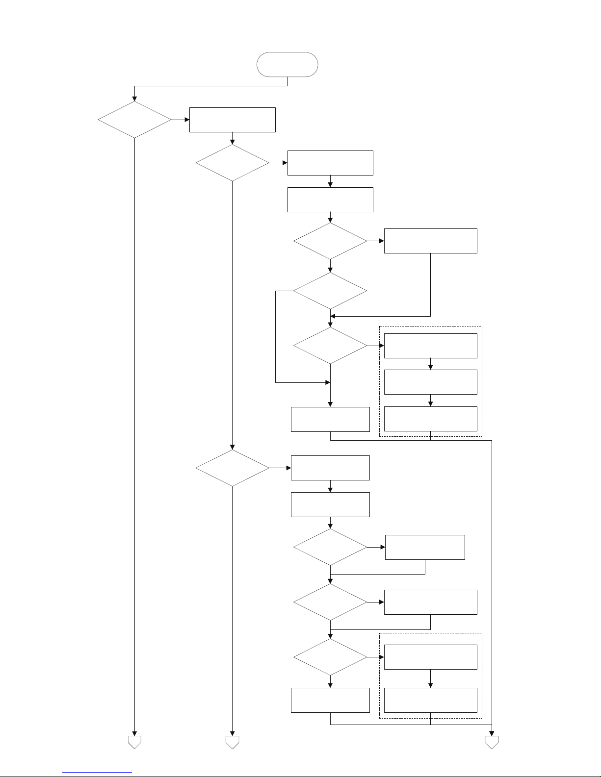
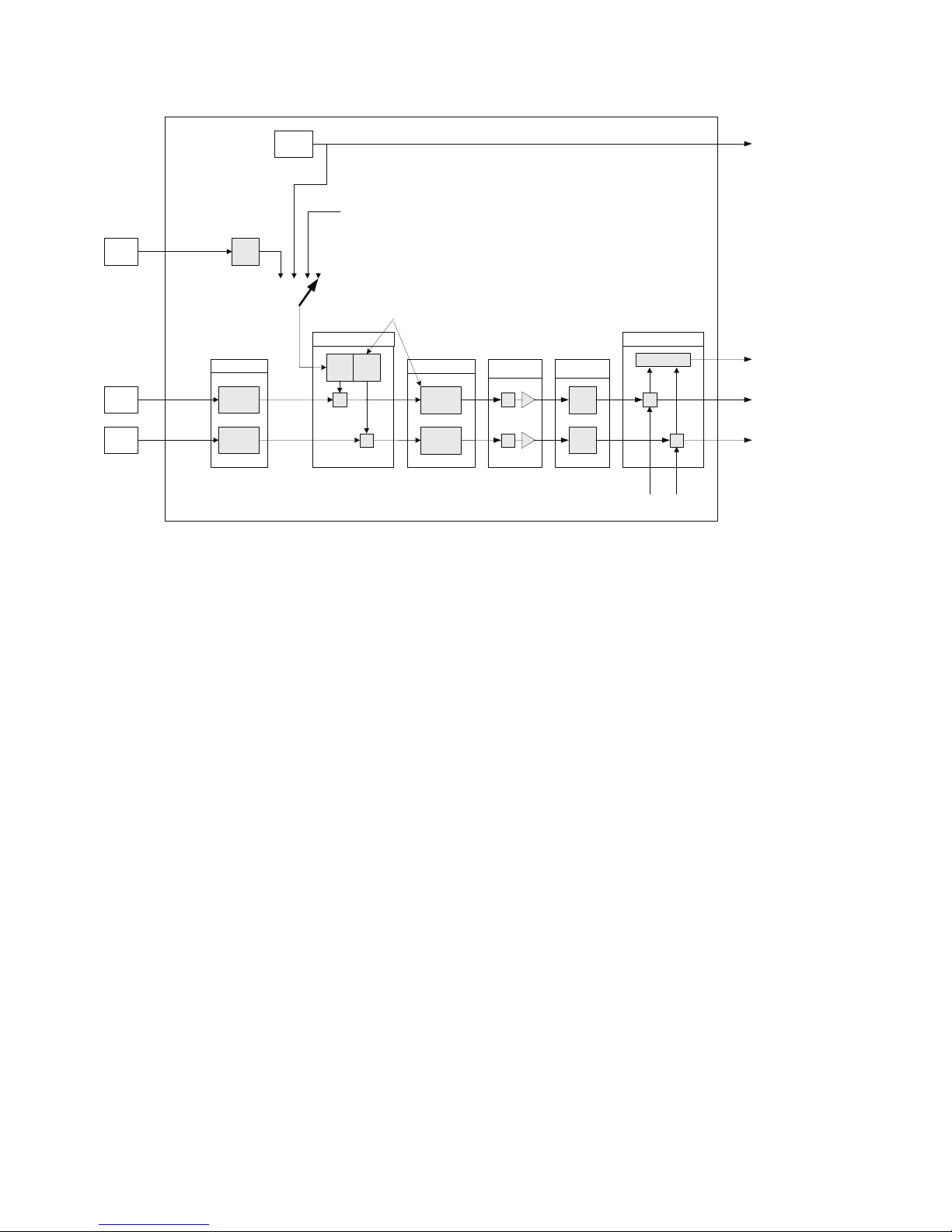
2.5 AI_Transducer Block Configuration Flowchart
Configure 5350
Transducer block
Temperature
measurement?
Set
PRIMARY_VALUE_UNIT
to F,R,C or K
RTD?
Thermo-couple?
Set LIN_TYPE to RTD
type (Pt100 etc.)
4-wire?
Set
SENSOR_CONNECTION
to 2-,3- or 4-wire.
Enter wire resistance in
Ohms for both wires to
COMP_WIRE1
2-wire?
Enter wire resistance in
Ohms for both wires to
COMP_WIRE2
YES
Enter setup for sensor 2:
YES
Set LIN_TYPE to TC
type (TC K etc.)
Set RJ_TYPE (internal,
external etc.)
Set LIN_TYPE_2 to RTD
type (Pt100 etc.)
Set
SENSOR_MEAS_TYPE
to single sensor type
Dual sensor?
Enter setup for sensor 2:
Set LIN_TYPE_2 to TC type
(TC K etc.)
Enter RJ temperature to
EXTERNAL_RJ_VALUE
RJ_TYPE
external?
YES
YES
RJ_TYPE
ext. 2.wire?
Enter wire resistance in
Ohms for both wires to
COMP_WIRE_RJ
YES
YES
YES
2c
Set
SENSOR_MEAS_TYPE
to single sensor type
2b
2a
Set SENSOR_MEAS_TYPE
to dual sensor type
Set SENSOR_MEAS_TYPE
to dual sensor type
YES
Dual sensor?
YES
Page 11
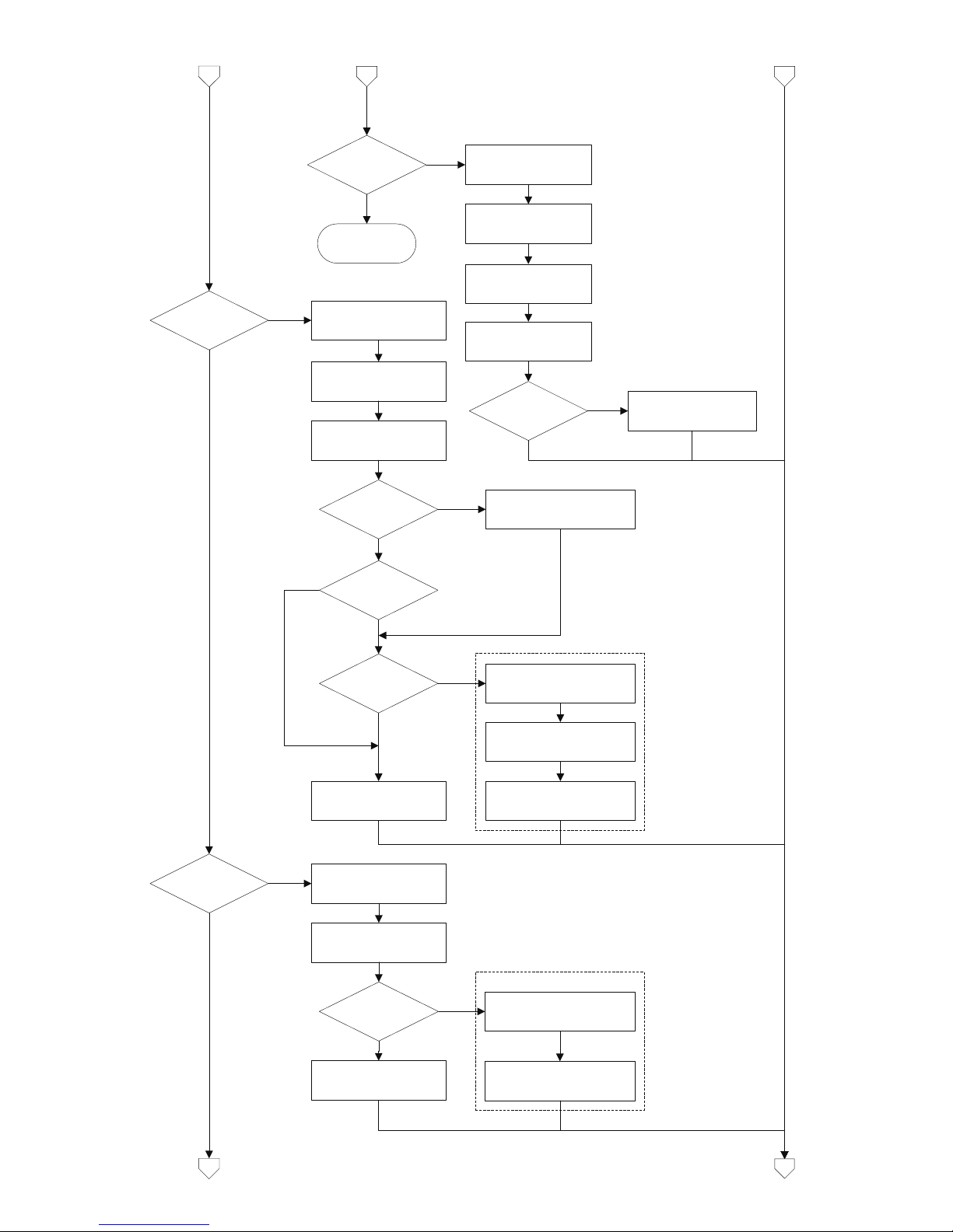
11
2c
RTD+Thermo-
couple?
2b
Set LIN_TYPE to TC
type (TC K etc.)
Set RJ_TYPE
(internal, external etc.)
Set
SENSOR_MEAS_TYPE
to dual sensor type
Set LIN_TYPE_2 to
RTD type (Pt100 etc.)
Enter RJ temperature to
EXTERNAL_RJ_VALUE
RJ_TYPE
external?
YES
YES
2a
Error! (try again)
Resistance?
Set
PRIMARY_VALUE_UNIT
to Ohm or kOhm
Set
SENSOR_CONNECTION
to 2-,3- or 4-wire.
Dual sensor?
Enter wire resistance in
Ohms for both wires to
COMP_WIRE1
2-wire?
YES
Enter setup for sensor 2:
YES
Set LIN_TYPE_2 to
”no linearisation” or
”linearisation table”
Set
SENSOR_MEAS_TYPE
to single sensor type
Set LIN_TYPE to
”no linearisation” or
”linearisation table”
Set SENSOR_MEAS_TYPE
to dual sensor type
Enter wire resistance in
Ohms for both wires to
COMP_WIRE2
Millivolts?
Set
PRIMARY_VALUE_UNIT
to V,mV or µV
Set LIN_TYPE to
”no linearisation” or
”linearisation table”
Dual sensor?
Set LIN_TYPE_2 to
”no linearisation” or
”linearisation table”
Set
SENSOR_MEAS_TYPE
to single sensor type
Set SENSOR_MEAS_TYPE
to dual sensor type
3b
3a
Enter setup for sensor 2:
YES
YES
YES
4-wire?
YES
Page 12

12
3b3a
Potentiometer?
Set
PRIMARY_VALUE_UNIT
to ”%”
Set
SENSOR_CONNECTION
to 3- or 4-wire.
Enter wire resistance in
Ohms for 2 wires to
COMP_WIRE1
3-wire?
YES
Enter setup
for sensor 2:
YES
Set LIN_TYPE_2 to
”no linearisation” or
”linearisation table”
Set
SENSOR_MEAS_TYPE
to single sensor type
Set LIN_TYPE to
”no linearisation” or
”linearisation table”
Set SENSOR_MEAS_TYPE
to dual sensor type
Enter wire resistance in
Ohms for 2 wires to
COMP_WIRE2
Error! (try again)
Finished.
Transducer block
is configured!
Enter Custom RTD
polynomial values
Linearisation
table?
Custom RTD?
Enter linearisation
table values
YES
YES
Enter Custom TC
polynomial values
Custom TC?
YES
Dual sensor?
YES
Page 13

13
2.6 - Transducer Block Examples Setup
2.6.1 Measurement of RTD with one sensor:
PRIMARY_VALUE_UNIT .......= K, °C, °F or °R
LIN_TYPE....................= Any RTD
LIN_TYPE_2 .................= N/A (ignored in setup check)
SENSOR_MEAS_TYPE.........= PV = SV_1, SV_2 not available
SENSOR_CONNECTION .......= 2-, 3- or 4-wire
SENSOR_CONNECTION_2 .....= N/A (ignored in setup check)
RJ_TYPE .....................= N/A (ignored in setup check)
Connections:
2.6.2 Measurement of RTD with two sensors:
PRIMARY_VALUE_UNIT .......= K, °C, °F or °R
LIN_TYPE....................= Any RTD
LIN_TYPE_2 .................= Any RTD
SENSOR_MEAS_TYPE.........= Anything, but not "PV = SV_1, SV_2 not available"
SENSOR_CONNECTION .......= 2- or 3-wire
SENSOR_CONNECTION_2 .....= Default set to 2-wire
RJ_TYPE .....................= N/A (ignored in setup check)
Connections:
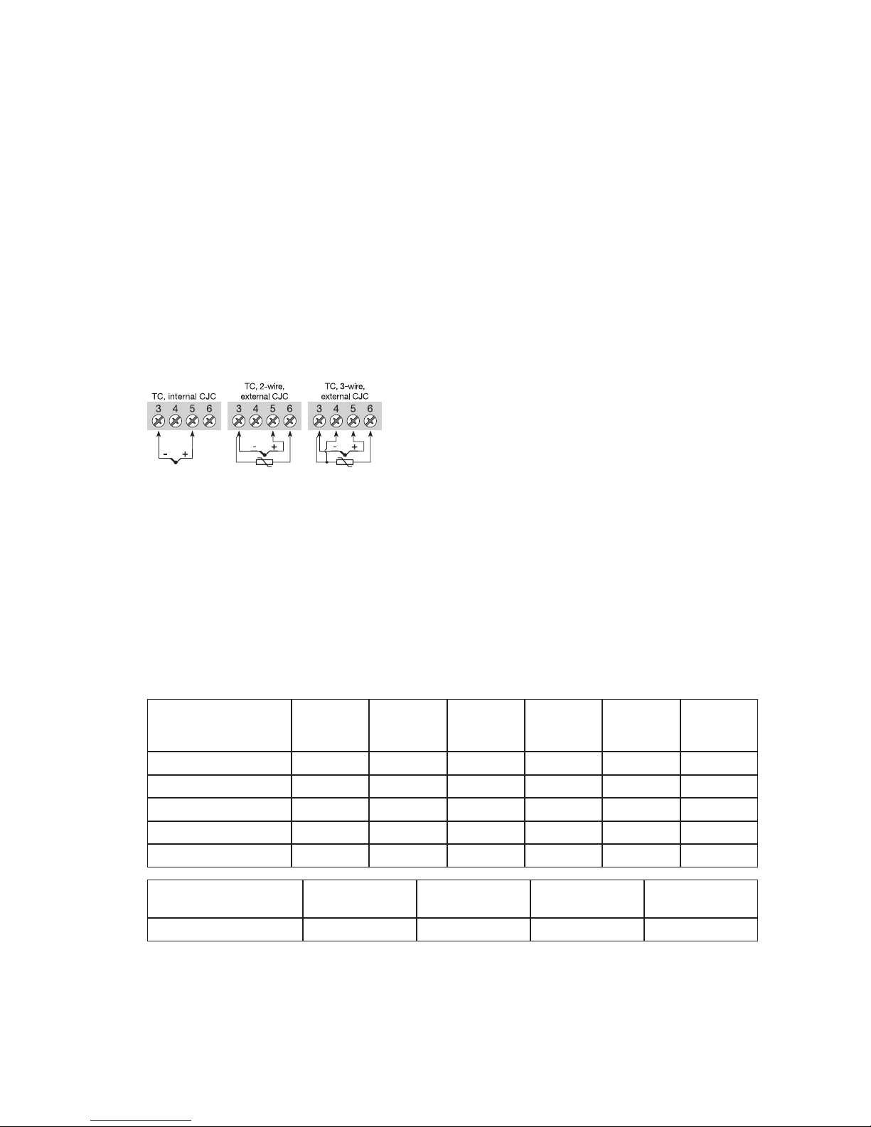
2.6.3 Measurement of thermocouple with one sensor:
PRIMARY_VALUE_UNIT .......= K, °C, °F or °R
LIN_TYPE....................= Any TC
LIN_TYPE_2 .................= N/A (ignored in setup check)
SENSOR_MEAS_TYPE.........= PV = SV_1, SV_2 not available
SENSOR_CONNECTION .......= N/A (ignored in setup check)
SENSOR_CONNECTION_2 .....= N/A (ignored in setup check)
RJ_TYPE .....................= No Reference Junction, Internal, External (constant value),
Sensor 2-wire or Sensor 3-wire
Connections:
Connections with two sensors
can be configured for
2 measurements, dierence,
average or redundancy
Page 14

14
2.6.4 Measurement of thermocouple with two sensors:
PRIMARY_VALUE_UNIT .......= K, °C, °F or °R
LIN_TYPE....................= Any TC
LIN_TYPE_2 .................= Any TC
SENSOR_MEAS_TYPE.........= Anything, but not "PV = SV_1, SV_2 not available"
SENSOR_CONNECTION .......= N/A (ignored in setup check)
SENSOR_CONNECTION_2 .....= N/A (ignored in setup check)
RJ_TYPE .....................= No RJ, Internal, External (constant value) or Sensor 2-wire
Connections:
2.6.5 Measurement of combined sensors (Sensor 1 = TC and Sensor 2 = RTD):
PRIMARY_VALUE_UNIT .......= K, °C, °F or °R
LIN_TYPE....................= Any TC
LIN_TYPE_2 .................= Any RTD
SENSOR_MEAS_TYPE.........= Anything, but not "PV = SV_1, SV_2 not available"
SENSOR_CONNECTION .......= N/A (ignored in setup check)
SENSOR_CONNECTION_2 .....= 2- or 3-wire
RJ_TYPE ....................= No Reference Junction, Internal, External (constant value)
Connections:
2.6.6 Measurement of resistance (linear) with one sensor:
PRIMARY_VALUE_UNIT .......= Ohm or kOhm
LIN_TYPE....................= No linearisation
LIN_TYPE_2 .................= N/A (ignored in setup check)
SENSOR_MEAS_TYPE.........= PV = SV_1, SV_2 not available
SENSOR_CONNECTION .......= 2-, 3- or 4-wire
SENSOR_CONNECTION_2 .....= N/A (ignored in setup check)
RJ_TYPE .....................= N/A (ignored in setup check)
Connections:
Connections with two sensors
can be configured for
2 measurements, dierence,
average or redundancy
Connections with two sensors
can be configured for
2 measurements, dierence,
average or redundancy
Page 15
15
2.6.7 Measurement of resistance (linear) with two sensors:
PRIMARY_VALUE_UNIT .......= Ohm or kOhm
LIN_TYPE....................= No linearisation
LIN_TYPE_2 .................= No linearisation
SENSOR_MEAS_TYPE.........= Anything, but not "PV = SV_1, SV_2 not available"
SENSOR_CONNECTION .......= 2- or 3-wire
SENSOR_CONNECTION_2 .....= Default set to 2-wire
RJ_TYPE .....................= N/A (ignored in setup check)
Connections:
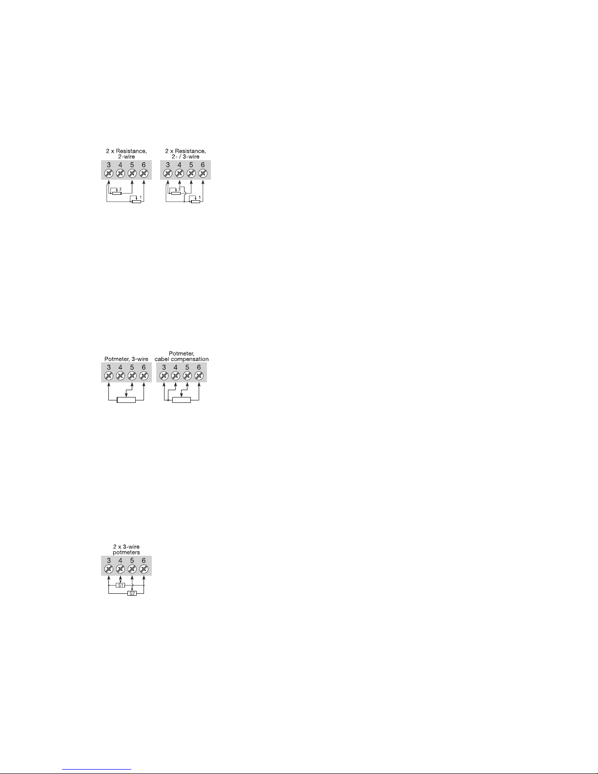
2.6.8 Measurement of potentiometer (linear) with one sensor:
PRIMARY_VALUE_UNIT .......= %
LIN_TYPE....................= No linearisation
LIN_TYPE_2 .................= N/A (ignored in setup check)
SENSOR_MEAS_TYPE.........= PV = SV_1, SV_2 not available
SENSOR_CONNECTION .......= 3- or 4-wire
SENSOR_CONNECTION_2 .....= N/A (ignored in setup check)
RJ_TYPE .....................= N/A (ignored in setup check)
Connections:
2.6.9 Measurement of potentiometer (linear) with two sensors:
PRIMARY_VALUE_UNIT .......= %
LIN_TYPE....................= No linearisation
LIN_TYPE_2 .................= No linearisation
SENSOR_MEAS_TYPE.........= Anything, but not "PV = SV_1, SV_2 not available"
SENSOR_CONNECTION .......= Default set to 3-wire
SENSOR_CONNECTION_2 .....= Default set to 3-wire
RJ_TYPE .....................= N/A (ignored in setup check)
Connections:
Connections with two sensors
can be configured for
2 measurements, dierence,
average or redundancy
Connections with two sensors
can be configured for
2 measurements, dierence,
average or redundancy
Page 16

16
2.6.10 Measurement of voltage (linear) with one sensor:
PRIMARY_VALUE_UNIT .......= µV, mV or V
LIN_TYPE....................= No linearisation
LIN_TYPE_2 .................= N/A (ignored in setup check)
SENSOR_MEAS_TYPE.........= PV = SV_1, SV_2 not available
SENSOR_CONNECTION .......= N/A (ignored in setup check)
SENSOR_CONNECTION_2 .....= N/A (ignored in setup check)
RJ_TYPE .....................= N/A (ignored in setup check)
Connections:
2.6.11 Measurement of voltage (linear) with two sensors:
PRIMARY_VALUE_UNIT .......= µV, mV or V
LIN_TYPE....................= No linearisation
LIN_TYPE_2 .................= No linearisation
SENSOR_MEAS_TYPE.........= Anything, but not "PV = SV_1, SV_2 not available"
SENSOR_CONNECTION .......= N/A (ignored in setup check)
SENSOR_CONNECTION_2 .....= N/A (ignored in setup check)
RJ_TYPE .....................= N/A (ignored in setup check)
Connections:
2.6.12 Measurement of 2 potentiometers (with Linear interpolation linearisation):
PRIMARY_VALUE_UNIT ....... = %
LIN_TYPE.................... = Table Linearisation
LIN_TYPE_2 ................. = Table Linearisation (same table as sensor 1)
SENSOR_MEAS_TYPE......... = Anything, but not "PV = SV_1, SV_2 not available"
SENSOR_CONNECTION ....... = Default set to 3-wire
SENSOR_CONNECTION_2 ..... = Default set to 3-wire
RJ_TYPE ..................... = N/A (ignored in setup check)
Connections:
The coordinates (x,y) describing the linear interpolation linearisation must be entered in PR_
CUST_LIN Block (PA Slot 4). See 2.9.2 Linear Interpolation Linearisation, Paramter List for
further details.
Example:
The coordinates for converting the signal from a logarithmic potentiometer to a linear signal.
TAB_ACTUAL_NUMBER = 10 (number of linearisation points to follow up to max 50)
TAB_XY_VALUE1 = 0,0; -100
TAB_XY_VALUE2 = 0,1; 0
TAB_XY_VALUE3 = 0,2; 100
TAB_XY_VALUE4 = 0,4; 200
Connections with two sensors
can be configured for
2 measurements, dierence,
average or redundancy
Connections with two sensors
can be configured for
2 measurements, dierence,
average or redundancy
Page 17
17
TAB_XY_VALUE5 = 0,8; 300
TAB_XY_VALUE6 = 1,6; 400
TAB_XY_VALUE7 = 3,2; 500
TAB_XY_VALUE8 = 6,4; 600
TAB_XY_VALUE9 = 12,8; 700
TAB_XY_VALUE10 = 25,6; 800
(Output will readout 325% with 1,0% potentiometer value)
2.6.13 Measurement of TC (with Custom Polynomial Linearisation) on sensor 1
PRIMARY_VALUE_UNIT = K, °C, °F or °R
LIN_TYPE = Custom defined TC
LIN_TYPE_2 = N/A (ignored in setup check)
SENSOR_MEAS_TYPE = PV = SV_1, SV_2 not available
SENSOR_CONNECTION = N/A (ignored in setup check)
SENSOR_CONNECTION_2 = N/A (ignored in setup check)
RJ_TYPE = No Reference Junction, Internal, External (constant value) or
Sensor 2-wire or Sensor 3-wire
Connections:
Now enter the Custom TC parameters in PR_CUST_LIN Block (PA Slot 4). See 2.9.4 Custom Polynomial Linearisation, Parameter List for further details.
Remember to enter values for the RJ polynomial if RJ_TYPE is any value other than “No reference Junction”.
Example:
The parameters and coecients for converting a special TC to a linear temperature signal.
CUSTOM_TC_NAME = Custom TC Example
CUSTOM_TC_POLY_COUNT = 5
CUSTOM_TC_MIN_IN = -6500.0
CUSTOM_TC_MIN_OUT = -100.0
CUSTOM_TC_MAX_OUT = 1200.0
A TC input of 5000 µV and an RJ temperature of 25ºC will make POLY_3 the active and the output will be:
U
RJ
= -3.94 * 10-1 + 3.94 * 101 * 25 + 2.65 * 10-2 * 252 - 1.11 * 10-4 * 253 = 1000 µV
This voltage is to be added to the TC voltage (5000 + 1000), and the resulting temperature will be:
4.18 + 2.26 * 10
-2
* 6000 + 1.41 * 10-7 * 60002 + 1.50 * 10
-11
* 60003 - 1.35 * 10
-15
* 60004 =
146.3 °C
See 2.9.3 Custom polynomial linearisation, Description for formula and further details.
CUSTOM_TC_POLY_X
max. input
limit in μV
for POLY_X
4th degree
coefficient
for POLY_X
3th degree
coefficient
for POLY_X
2th degree
coefficient
for POLY_X
1st degree
coefficient
for POLY_X
0 degree
coefficient
for POLY_X
CUSTOM_TC_POLY_1 -3200.0 -3.84E-13 -5.65E-9 -3.36E-5 -6.10E-2 -8.44E1
CUSTOM_TC_POLY_2 3500.0 -8.13E-15 7.29E-11 -4.18E-7 2.53E-2 -1.08E-2
CUSTOM_TC_POLY_3 10000.0 -1.35E-15 1.50E-11 1.41E-7 2.26E-2 4.18
CUSTOM_TC_POLY_4 30000.0 3.49E-18 2.19E-12 -1.53E-7 2.68E-2 -9.26
CUSTOM_TC_POLY_5 70000.0 6.27E-17 -8.76E-12 5.34E-7 8.69E-3 1.65E2
3th degree
coefficient
2th degree
coefficient
1st degree
coefficient
0 degree
coefficient
CUSTOM_TC_RJ_POLY -1.11E-4 2.65E-2 3.94E1 3.94E-1
Page 18
18
RJ
temp.
Intern
temp.
INTERN_TEMP
EXTERNAL_RJ_VALUE
LIN
R.J. Comp.
RJ_TYPE
Input
INPUT1
INPUT2
T1
T2
Linearisation
+
+ LIN
LIN
RJ_TEMP
(none)
Arithmetic
+
+
+,-, redund.
SECONDARY_VALUE_1
SECONDARY_VALUE_2
PRIMARY_VALUE
SENSOR_MEAS_TYPE
BIAS_1
BIAS_2
LIN
LIN_TYPE_1/2
SENSOR_CONNECTION_1/2
COMP_WIRE_1/2
Process
calibration
+
+
Min/Max hold
min/
max
min/
max
MIN_SENSOR_VALUE_1/2
MAX_SENSOR_VALUE_1/2
RTDX_FACTOR_1/2
CAL_POINT_HI_1/2
CAL_ACTUAL_HI_1/2
CABLE_RES1/2
RJ
RJ_COMP_WIRE
SENSOR_WIRE_CHECK_1/2
SENSOR_WIRE_CHECK_RJ
CUSTOM_TC_..
TAB_X_Y_VALUE
CUSTOM_RTD_..
(Channel_4)
(Channel_1)
(Channel_2)
(Channel_3)
AI_TRANSDUCER and PR_CUST_LIN schematic
CAL_POINT_LO_1/2
CAL_ACTUAL_LO_1/2
2.7 AI_Transducer and PR_CUST_LIN Block, Schematic
Page 19

19
2.8 AI_TRANSDUCER Block Parameter List
2.8.1 Sensor characterising parameters
Parameter
Rel.
Index FFDescription Type Store
Size
byte
RO /
R/W
Min. Max. Default
PRIMARY_VALUE_UNIT
14
Selects the unit code of the PRIMARY_VALUE and other
values.
1000 = K (Kelvin)
1001 = °C (degree Celsius)
1002 = °F (degree Fahrenheit)
1003 = Rk (Rankine)
1240 = V (volt)
1243 = mV millivolt
1244 = µV microvolt
1281 = Ohm Ohm
1284 = kOhm kiloOhm
1342 = % (percent)
Un-
signed 16SRC 2 R/W
1001
(°C)
LIN_TYPE
18
Select the type of sensor 1:
0 = no linearisation
1 = linearisation table
100 = RTD Pt10 a = 0.003850 (IEC 60751)
101 = RTD Pt50 a = 0.003850 (IEC 60751)
102 = RTD Pt100 a = 0.003850 (IEC 60751))
103 = RTD Pt200 a = 0.003850 (IEC 60751))
104 = RTD Pt500 a = 0.003850 (IEC 60751))
105 = RTD Pt1000 a = 0.003850 (IEC 60751)
106 = RTD Pt10 a = 0.003916 (JIS C1604-81)
107 = RTD Pt50 a = 0.003916 (JIS C1604-81)
108 = RTD Pt100 a = 0.003916 (JIS C1604-81)
122 = RTD Ni50 a = 0.006180 (DIN 43760)
123 = RTD Ni100 a = 0.006180 (DIN 43760)
124 = RTD Ni120 a = 0.006180 (DIN 43760)
125 = RTD Ni1000 a = 0.006180 (DIN 43760)
126 = RTD Cu10 a = 0.004270
127 = RTD Cu100 a = 0.004270
128 = TC Type B, Pt30Rh-Pt6Rh (IEC 584)
129 = TC Type C (W5), W5-W26Rh (ASTM E 988)
130 = TC Type D (W3), W3-W25Rh (ASTM E 988)
131 = TC Type E, Ni10Cr-Cu45Ni (IEC 584)
133 = TC Type J, Fe-Cu45Ni (IEC 584)
134 = TC Type K, Ni10Cr-Ni5 (IEC 584)
135 = TC Type N, Ni14CrSi-NiSi (IEC 584)
136 = TC Type R, Pt13Rh-Pt (IEC 584)
137 = TC Type S, Pt10Rh-Pt (IEC 584)
138 = TC Type T, Cu-Cu45Ni (IEC 584)
139 = TC Type L, Fe-CuNi (DIN 43710)
140 = TC Type U, Cu-CuNi (DIN 43710)
240 = Custom-defined TC
241 = Custom-defined RTD
242 = Custom-defined RTD PtX a=0.003850
(X factor of Pt1)
243 = Custom-defined RTD NiX a=0.006180 (X factor of Ni1)
244 = Custom-defined RTD CuX a=0.004270 (X factor of Cu1)
245 = Custom-defined RTD PtX a=0.003916 (X factor of Pt1)
Un-
signed 8SRC 1 R/W
102
(Pt100)
UPPER_SENSOR_LIMIT
21
Physical upper limit function of sensor1 (e.g. Pt 100 =
850°C) and input range.
The unit of UPPER_SENSOR_LIMIT is the PRIMARY_
VALUE_UNIT.
Float N 4 RO 850
LOWER_SENSOR_LIMIT
22
Physical lower limit function of sensor1 (e.g. Pt 100 =
-200°C) and input range.
The unit of LOWER_SENSOR_LIMIT is the PRIMARY_
VALUE_UNIT.
Float N 4 RO -200
LOWER_SENSOR_LIMIT_2
39
Physical lower limit function of sensor2 (e.g. Pt 100 =
-200°C) and input range.
The unit of LOWER_SENSOR_LIMIT is the PRIMARY_
VALUE_UNIT.
Float N 4 RO -200
UPPER_SENSOR_LIMIT_2
40
Physical upper limit function of sensor2 (e.g. Pt 100 =
+850°C) and input range.
The unit of UPPER_SENSOR_LIMIT is the PRIMARY_
VALUE_UNIT.
Float N 4 RO 850
LIN_TYPE_2
41
Select the type of sensor 2:
See LIN_TYPE for selection and supported types
Un-
signed 8SRC 1 R/W 102
Page 20

20
AI_TRANSDUCER Block Parameter List
2.8.2 RTD / Resistor specific parameters
Parameter
Rel.
Index FFDescription Type Store
Size
byte
RO /
R/W
Min. Max. Default
SENSOR_CONNECTION
35
Connection to sensor 1, select for 2-, 3- and 4-wire connection. Ignored if sensor 1 is not a resistive sensor.
Defined codes:
0 = 2 wires
1 = 3 wires
2 = 4 wires
Un-
signed 8SRC 1 R/W 1
COMP_WIRE1
36
Value in OHM to compensate line resistance when
Sensor 1 is a resistive sensor, connected with 2 wires.
Float SRC 4 R/W 0 100 0
COMP_WIRE2
37
Value in OHM to compensate line resistance when
Sensor 2 is a resistive sensor, connected with 2 wires.
Float SRC 4 R/W 0 100 0
SENSOR_CONNECTION_2
38
Connection to sensor 2, select for 2-, 3- and 4-wire connection. Ignored if sensor 2 is not a resistive sensor.
Defined codes:
0 = 2 wires
1 = 3 wires
Un-
signed 8SRC 1 R/W 0
CABLE_RES1
63
For 3- or 4-wire resistance measurements.
Indicates the measured cable resistance in the wire
connected to terminal 3. For 3-wire measurements it is
multiplied by 2
Float D 4 RO 0,0
CABLE_RES2
64
For 4-wire resistance measurements.
Indicates the measured cable resistance in the wire connected to terminal 6.
Float D 4 RO 0,0
RTDX_FACTOR_1
65
Indicates the X factor for custom defined PtX, NiX, CuX
for LIN_TYPE
Un-
signed 16SRC 2 R/W 100
RTDX_FACTOR_2
66
Indicates the X factor for custom defined PtX, NiX, CuX
for LIN_TYPE_2
Un-
signed 16SRC 2 R/W 100
2.8.3 Thermocouple specific parameters
Parameter
Rel.
Index FFDescription Type Store
Size
byte
RO /
R/W
Min. Max. Default
RJ_TEMP
32
Reference junction temperature. The unit of RJ_TEMP is
the PRIMARY_VALUE_UNIT. If PRIMARY_VALUE_UNIT is
no temperature unit (e.g. mV) RJ_TEMP is stated in °C.
Float D 4 RO 0
RJ_TYPE
33
Select reference junction from internal to fixed value.
Ignored for sensors which are not thermocouple types.
Defined codes:
0 = No reference: Compensation is not used (e.g. for
TC type B).
1 = Internal: Reference junction temperature is
measured by the device itself, via
an internally mounted sensor.
2 = External: The fixed value EXTERNAL_RJ_
VALUE is used for compensation.
The reference junction must be kept
at a constant temperature (e.g. by a
reference junction thermostat).
3 = Sensor, 2-w.: Reference junction temperature is
measured by external 2-wire con nected Pt100 sensor.
4 = Sensor, 3-w: Reference junction temperature is
measured by external 3-wire con nected Pt100 sensor.
Un-
signed 8SRC 1 R/W 0
EXTERNAL_RJ_VALUE
34
Fixed temperature value of an external reference junction. The unit of EXTERNAL_RJ_VALUE is the PRIMARY_
VALUE_UNIT. If PRIMARY_VALUE_UNIT is no temperature
unit (e.g. mV) EXTERNAL_RJ_VALUE is stated in °C.
Float SRC 4 R/W
-40
(°C)
135
(°C)
0
RJ_COMP_WIRE
42
Value in OHM to compensate line resistance when
External RJ sensor, connected with 2 wires is used.
Float SRC 4 R/W 0 100 0
Page 21

21
AI_TRANSDUCER Block Parameter List
2.8.4 Output conditioning parameters
Parameter
Rel.
Index FFDescription Type Store
Size
byte
RO /
R/W
Min. Max. Default
SENSOR_MEAS_TYPE
17
Mathematical function to calculate PRIMARY_VALUE (PV).
Defined codes:
0: PV = SV_1
1: PV = SV_2
128: PV = SV_1 - SV_2 Difference
129: PV = SV_2 - SV_1 Difference
192: PV = ½ * (SV_1 + SV_2) Average
193: PV = ½ * (SV_1 + SV_2) Average, but SV_1 or
SV_2 if the other is wrong (input_fault_x ≠0)
220: PV = SV_1, SV_2 not available. Used for single
sensor applications. If selected, Sensor 2 will
not be measured. All parameters exclusively
related to Sensor 2 are not available, and no
alarms will be generated for Sensor 2.
221: PV = SV_1, but SV_2 if SV_1 is wrong
(INPUT_FAULT_1 ≠0)
222: PV = SV_2, but SV_1 if SV_2 is wrong
(INPUT_FAULT_2 ≠0)
Un-
signed 8SRC 1 R/W 220
BIAS_1
19
Bias that can be algebraically added to process value of
sensor 1, SV1.
The unit of BIAS_1 is the PRIMARY_VALUE_UNIT.
Float SRC 4 R/W 0
BIAS_2
20
Bias that can be algebraically added to process value of
sensor 2, SV2.
The unit of BIAS_2 is the PRIMARY_VALUE_UNIT.
Float SRC 4 R/W 0
MAX_SENSOR_VALUE_1
28
Holds the maximum SECONDARY_VALUE_1. The unit is
defined in
SECONDARY_VALUE_1.
Float N 4 R/W 0
MIN_SENSOR_VALUE_1
29
Holds the minimum SECONDARY_VALUE_1. The unit is
defined in
SECONDARY_VALUE_1.
Float N 4 R/W 0
MAX_SENSOR_VALUE_2
30 See. MAX_SENSOR_VALUE_1 Float N 4 R/W 0
MIN_SENSOR_VALUE_2
31 See. MIN_SENSOR_VALUE_1 Float N 4 R/W 0
2.8.5 Output parameters
Parameter
Rel.
Index FFDescription Type Store
Size
byte
RO /
R/W
Min. Max. Default
PRIMARY_VALUE
13
Process value, function determined by SENSOR_MEAS_
TYPE of SECONDARY_VALUE_1/2.
The unit of PRIMARY_VALUE is the PRIMARY_VALUE_
UNIT.
FF Channel 1 Output. PA Channel 280
DS-33 D 5 RO 0
SECONDARY_VALUE_1
15
Process value connected to sensor 1 corrected by
BIAS_1. The unit of SECONDARY_VALUE_1 is the
PRIMARY_VALUE_UNIT.
FF Channel 2 Output, PA Channel 282
DS-33 D 5 RO 0
SECONDARY_VALUE_2
16
Process value connected to sensor 2 corrected by
BIAS_2. The unit of SECONDARY_VALUE_2 is the
PRIMARY_VALUE_UNIT.
FF Channel 3 Output, PA Channel 283
DS-33 D 5 RO 0
INTERN_TEMP
45
Internal electronics temperature. The unit of INTERN_
TEMP is the PRIMARY_VALUE_UNIT. If PRIMARY_VALUE_
UNIT is no temperature unit (e.g. mV) INTERN_TEMP is
stated in °C.
FF Channel 4 Output, PA Channel 341
DS-33 D 5 RO 0
Page 22

22
AI_TRANSDUCER Block Parameter List
2.8.6 Diagnostic parameters
Parameter
Rel.
Index FFDescription Type Store
Size
byte
RO /
R/W
Min. Max. Default
INPUT_FAULT_GEN
23
Input malfunction: Diagnosis object for errors that concern all values
0 = device OK
Bit:
0 = Rj error
1 = Hardware error
2 – 4 = reserved
5 – 7 = manufacturer-specific
Un-
signed 8D 1 RO 0
INPUT_FAULT_1
24
Input malfunction: Diagnosis object for errors that concern SV_1
0 = Input OK
Bit:
0 = underrange
1 = overrange
2 = lead breakage
3 = short circuit
4 – 5 = reserved
6 – 7 = manufacturer-specific
Un-
signed 8D 1 RO 0
INPUT_FAULT_2
25
Input malfunction: Diagnosis object for errors that concern SV_2
0 = Input OK
Bit definition see INPUT_FAULT_1
Un-
signed 8D 1 RO 0
RJ_FAULT
43
Input malfunction: Diagnosis object for errors that concern RJ sensor.
0 = Input OK
Bit:
0 = underrange
1 = overrange
2 = lead breakage
3 = short circuit
Un-
signed 8D 1 RO 0
HW_ERROR
62
Diagnostic bit value indicating hardware status
0 = hardware OK
Bit:
0 = Input power supply error
1 = Input initialisation error
2 = Input communication error
3 = Internal temperature sensor error
4 = Device not factory calibrated
5 – 6 = reserved
7 = Watchdog initiated cold start occurred
Un-
signed 8D 1 RO 0
2.8.7 Sensor error detection parameters
Parameter
Rel.
Index FFDescription Type Store
Size
byte
RO /
R/W
Min. Max. Default
SENSOR_WIRE_CHECK_1
26
Enables lead breakage and short circuit detection for
Sensor 1.
List of valid values:
0 = Lead breakage and short circuit detection enable.
1 = Lead breakage detection enable, short circuit
detection disable.
2 = Lead breakage detection disable, short circuit
detection enable.
3 = Lead breakage and short circuit detection disable.
Un-
signed 8SRC 1 R/W 3
SENSOR_WIRE_CHECK_2
27
Enables lead breakage and short circuit detection for
Sensor 2.
Valid values: see SENSOR_WIRE_CHECK_1.
Un-
signed 8SRC 1 R/W 3
SENSOR_WIRE_CHECK_RJ
44
Enables lead breakage and short circuit detection for RJ
Sensor.
Valid values: see SENSOR_WIRE_CHECK_1.
Un-
signed 8SRC 1 R/W 3
Page 23

23
AI_TRANSDUCER Block Parameter List
2.8.8 Sensor calibration, Description
Sensor calibration is a very useful function when the transmitter output needs to be adjusted to the sensor signal, e.g. when the temperature sensor does not correspond to the ideal values for the selected
temperature range. The results depend on the accuracy of the calibrator or reference equipment. In the following a temperature sensor calibration is described, however the principle can be used for all input types.
SENSOR_CAL_METHOD_1 / 2 defines the use of either “Factory trim Standard” (the factory defined values
calculated according to the valid norms) or “User Trim Standard” (the sensor calibrated values) in the transmitter for sensor 1 and 2 respectively. During sensor calibration SENSOR_CAL_METHOD_1 / 2 must be set
to “Factory trim Standard” = 103.
The sensor calibration function in PR5350 will change the slope of the linarisation curve so the curve is
adjusted to the connected sensor. To obtain accurate temperature measurement in the range e.g. 0...100
°C apply to the sensor a temperature e.g. of 5 °C as the low temperature and e.g. 95 °C as the high temperature through a precise temperature calibrator.
At sensor calibration the succeeding procedure must be followed precisely (Example: sensor 1):
1. SENSOR_CAL_METHOD_1 = 103
2. Apply the low temperature of the calibrator to the sensor
3. CAL_POINT_LO_1 = 5.00 (type in the low temperature of the calibrator)
4. CAL_ACTUAL_LO_1 = 1.00 (The measurement of the deviation starts by typing in a random value)
5. Apply the high temperature of the calibrator to the sensor
6. CAL_POINT_HI_1 = 95.00 (type in the high temperature of the calibrator)
7. CAL_ACTUAL_HI_1 = 1.00 (The measurement of the deviation starts by typing in a random value
and PR5350 calculates the curve slope according to the measured
deviations.)
8. SENSOR_CAL_METHOD_1 = 104 (the sensor calibration just carried out is used)
2.8.9 Sensor Calibration Parameters
Parameter
Rel.
Index FFDescription Type Store
Size
byte
RO /
R/W
Min. Max. Default
CAL_POINT_LO_1
46
The low calibration value applied to sensor 1
The value from either a calibrator or a reference equipment.
Float SRC 4 R/W -10
38
CAL_ACTUAL_LO_1
47
Entering any value will force the device to automatically
measure and store the actual low point value. Must be
entered with the applied CAL_POINT_LO_1 value
Float SRC 4 R/W -10
38
CAL_POINT_HI_1
48
The high calibration value applied to sensor 1
The value from either a calibrator or a reference equipment.
Float SRC 4 R/W 10
38
CAL_ ACTUAL _HI_1
49
Entering any value will force the device to automatically
measure and store the actual high point value. Must be
entered with the applied CAL_POINT_HI_1 value
Float SRC 4 R/W 10
38
SENSOR_CAL_METHOD_1
50
Enables or disables the last sensor calibration for
sensor 1
103 = Factory trim standard (calibration values disabled)
104 = User trim standard (calibration values enabled)
Un-
signed 8SRC 1 R/W 103
SENSOR_CAL_LOC_1
51 The last location of the calibrated sensor
OCTET_
STRING
SRC 32 R/W ” ”
SENSOR_CAL_DATE_1
52 The last date on which the calibration was performed
7 * Un-
signed 8SRC 7 R/W
0,0,0,0,
1,1,103
SENSOR_CAL_WHO_1
53
The name of the person responsible for the last sensor
calibration
OCTET_
STRING
SRC 32 R/W ” ”
CAL_POINT_LO_2
54
The low calibration value applied to sensor 2
The value from either a calibrator or a reference equipment.
Float SRC 4 R/W -10
38
CAL_ACTUAL_LO_2
55
Entering any value will force the device to automatically
measure and store the actual low point value. Must be
entered with the applied CAL_POINT_LO_2 value
Float SRC 4 R/W
-10
38
Page 24

24
Parameter
Rel.
Index FFDescription Type Store
Size
byte
RO /
R/W
Min. Max. Default
CAL_POINT_HI_2
56
The high calibration value applied to sensor 2
The value from either a calibrator or a reference equipment.
Float SRC 4 R/W 10
38
CAL_ACTUAL_HI_2
57
Entering any value will force the device to automatically
measure and store the actual high point value. Must be
entered with the applied CAL_POINT_HI_2 value
Float SRC 4 R/W 10
38
SENSOR_CAL_METHOD_2
58
Enables or disables the last sensor calibration for
sensor 2
103 = Factory trim standard (calibration values disabled)
104 = User trim standard (calibration values enabled)
Un-
signed 8SRC 1 R/W 103
SENSOR_CAL_LOC_2
59 The last location of the calibrated sensor
OCTET_
STRING
SRC 32 R/W » »
SENSOR_CAL_DATE_2
60
The last date on which the calibration was performed
7 * Un-
signed 8SRC 7 R/W
0,0,0,0,
1,1,103
SENSOR_CAL_WHO_2
61
The name of the person responsible for the last sensor
calibration
OCTET_
STRING
SRC 32 R/W » »
Page 25

25
2.9 PR_CUST_LIN Block Parameter List
2.9.1 Linear interpolation linearisation, Description
LinType 1 = “Linearisation Table” generates a customer specific linear interpolation linearisation. Linear
interpolation linearisation can be used on mV, ohmic and potentiometer signals.The linear interpolation
linearisation is defined by straight lines drawn between the entered X / Y (input / output) coordinates.
The linearisation table must consist of 10 to 50 coordinate sets. The X values of the coordinates must
be entered in ascending order. The lowest and highest X values function as the lower and the upper limit respectively. All X values must be entered as µV, Ohm or % for Voltage, Resistance or Potentiometer
measurements in that order. The table output will be converted to actual chosen PRMARY_VALUE_UNIT
(Example: 1000 / 3000 as X / Y values: output will read 3,00 if PRIMARY_VALUE_UNIT is set to “mV” and 1
mV is connected to input).
2.9.2 Linear Interpolation Linearisation, Parameter List.
Parameter
Rel.
Index FFDescription Type Store
Size
byte
RO /
R/W
Min. Max. Default
TAB_MIN_NUMBER
34 Minimum number of linearisation points allowed (10)
Un-
signed 8N 1 RO 10
TAB_MAX_NUMBER
35 Maximum number of linearisation points allowed (50)
Un-
signed 8N 1 RO 50
TAB_ACTUAL_NUMBER
36 Number of linearisation points in the linearisation table.
Un-
signed 8SRC 1 R/W 11
TAB_X_Y_VALUE1
37 Linearisation x,y coordinate 1
Float
array
SRC 8 R/W 0, 0
TAB_X_Y_VALUE2
38 Linearisation x,y coordinate 2
Float
array
SRC 8 R/W
1000,
100
TAB_X_Y_VALUE3
39 Linearisation x,y coordinate 3
Float
array
SRC 8 R/W
2000,
200
TAB_X_Y_VALUE4
40 Linearisation x,y coordinate 4
Float
array
SRC 8 R/W
3000,
300
TAB_X_Y_VALUE5
41 Linearisation x,y coordinate 5
Float
array
SRC 8 R/W
4000,
400
TAB_X_Y_VALUE6
42 Linearisation x,y coordinate 6
Float
array
SRC 8 R/W
5000,
500
TAB_X_Y_VALUE7
43 Linearisation x,y coordinate 7
Float
array
SRC 8 R/W
6000,
600
TAB_X_Y_VALUE8
44 Linearisation x,y coordinate 8
Float
array
SRC 8 R/W
7000,
700
TAB_X_Y_VALUE9
45 Linearisation x,y coordinate 9
Float
array
SRC 8 R/W
8000,
800
TAB_X_Y_VALUE10
46 Linearisation x,y coordinate 10
Float
array
SRC 8 R/W
9000,
900
TAB_X_Y_VALUE11
47 Linearisation x,y coordinate 11
Float
array
SRC 8 R/W
10000,
1000
TAB_X_Y_VALUE12
48 Linearisation x,y coordinate 12
Float
array
SRC 8 R/W 0, 0
TAB_X_Y_VALUE13
49 Linearisation x,y coordinate 13
Float
array
SRC 8 R/W 0, 0
TAB_X_Y_VALUE14
50 Linearisation x,y coordinate 14
Float
array
SRC 8 R/W 0, 0
TAB_X_Y_VALUE15
51 Linearisation x,y coordinate 15
Float
array
SRC 8 R/W 0, 0
TAB_X_Y_VALUE16
52 Linearisation x,y coordinate 16
Float
array
SRC 8 R/W 0, 0
TAB_X_Y_VALUE17
53 Linearisation x,y coordinate 17
Float
array
SRC 8 R/W 0, 0
TAB_X_Y_VALUE18
54 Linearisation x,y coordinate 18
Float
array
SRC 8 R/W 0, 0
TAB_X_Y_VALUE19
55 Linearisation x,y coordinate 19
Float
array
SRC 8 R/W 0, 0
TAB_X_Y_VALUE20
56 Linearisation x,y coordinate 20
Float
array
SRC 8 R/W 0, 0
TAB_X_Y_VALUE21
57 Linearisation x,y coordinate 21
Float
array
SRC 8 R/W 0, 0
TAB_X_Y_VALUE22
58 Linearisation x,y coordinate 22
Float
array
SRC 8 R/W 0, 0
Page 26

26
Parameter
Rel.
Index FFDescription Type Store
Size
byte
RO /
R/W
Min. Max. Default
TAB_X_Y_VALUE23
59 Linearisation x,y coordinate 23
Float
array
SRC 8 R/W 0, 0
TAB_X_Y_VALUE24
60 Linearisation x,y coordinate 24
Float
array
SRC 8 R/W 0, 0
TAB_X_Y_VALUE25
61 Linearisation x,y coordinate 25
Float
array
SRC 8 R/W 0, 0
TAB_X_Y_VALUE26
62 Linearisation x,y coordinate 26
Float
array
SRC 8 R/W 0, 0
TAB_X_Y_VALUE27
63 Linearisation x,y coordinate 27
Float
array
SRC 8 R/W 0, 0
TAB_X_Y_VALUE28
64 Linearisation x,y coordinate 28
Float
array
SRC 8 R/W 0, 0
TAB_X_Y_VALUE29
65 Linearisation x,y coordinate 29
Float
array
SRC 8 R/W 0, 0
TAB_X_Y_VALUE30
66 Linearisation x,y coordinate 30
Float
array
SRC 8 R/W 0, 0
TAB_X_Y_VALUE31
67 Linearisation x,y coordinate 31
Float
array
SRC 8 R/W 0, 0
TAB_X_Y_VALUE32
68 Linearisation x,y coordinate 32
Float
array
SRC 8 R/W 0, 0
TAB_X_Y_VALUE33
69 Linearisation x,y coordinate 33
Float
array
SRC 8 R/W 0, 0
TAB_X_Y_VALUE34
70 Linearisation x,y coordinate 34
Float
array
SRC 8 R/W 0, 0
TAB_X_Y_VALUE35
71 Linearisation x,y coordinate 35
Float
array
SRC 8 R/W 0, 0
TAB_X_Y_VALUE36
72 Linearisation x,y coordinate 36
Float
array
SRC 8 R/W 0, 0
TAB_X_Y_VALUE37
73 Linearisation x,y coordinate 37
Float
array
SRC 8 R/W 0, 0
TAB_X_Y_VALUE38
74 Linearisation x,y coordinate 38
Float
array
SRC 8 R/W 0, 0
TAB_X_Y_VALUE39
75 Linearisation x,y coordinate 39
Float
array
SRC 8 R/W 0, 0
TAB_X_Y_VALUE40
76 Linearisation x,y coordinate 40
Float
array
SRC 8 R/W 0, 0
TAB_X_Y_VALUE41
77 Linearisation x,y coordinate 41
Float
array
SRC 8 R/W 0, 0
TAB_X_Y_VALUE42
78 Linearisation x,y coordinate 42
Float
array
SRC 8 R/W 0, 0
TAB_X_Y_VALUE43
79 Linearisation x,y coordinate 43
Float
array
SRC 8 R/W 0, 0
TAB_X_Y_VALUE44
80 Linearisation x,y coordinate 44
Float
array
SRC 8 R/W 0, 0
TAB_X_Y_VALUE45
81 Linearisation x,y coordinate 45
Float
array
SRC 8 R/W 0, 0
TAB_X_Y_VALUE46
82 Linearisation x,y coordinate 46
Float
array
SRC 8 R/W 0, 0
TAB_X_Y_VALUE47
83 Linearisation x,y coordinate 47
Float
array
SRC 8 R/W 0, 0
TAB_X_Y_VALUE48
84 Linearisation x,y coordinate 48
Float
array
SRC 8 R/W 0, 0
TAB_X_Y_VALUE49
85 Linearisation x,y coordinate 49
Float
array
SRC 8 R/W 0, 0
TAB_X_Y_VALUE50
86 Linearisation x,y coordinate 50
Float
array
SRC 8 R/W 0, 0
2.9.3 Custom polynomial linearisation, Description
Polynomial linearisation can be used on mV and ohmic input signals. Polynomial linearisation is executed according to the function f(x) = a
0
+ a
1
*
x + a
2
*
x
2
+ a
3
*
x
3
+ a
4
*
x
4
, in which a0...a4 equal the coecients
for a fourth order polynomial and x equals the input value. This function requires that the user can obtain
or calculate the coecients of up to 5 fourth order polynomials. Various computer programs such as Math
Cad can calculate these coecients. If the preceding text is unfamiliar one should use the function table
linearisation in case of customer specific linearisation.
LIN_TYPE 240 = “Custom defined TC” generates a customer specific polynomial linearisation. The function
is primarily suitable for specific thermo elements but also for millivolt signals if the user can accept to enter the input and the output values of the polynomial in µV and °C respectively.
LIN_TYPE 241 = “Custom defined RTD” generates a customer specific polynomial linearisation. The function is particularly suitable for specific RTD sensors but also for non-linear ohmic signals if the user can
Page 27

27
accept to enter the input and output values of the polynomials in ohm and °C respectively.
Please remember that polynomial linearisation is absolute. The output value is calculated continuously according to the applied input value and the function formula. The max. input range can be limited precisely
to the input range in which the polynomial linearisation will be used. The PRIMARY_VALUE_UNIT defines
the unit of the values provided by the AI_TRANSDUCER BLOCK. The parameter OUT_SCALE in the AI block
can scale the values and change the unit to e.g. mV or ohm.
2.9.4 Custom Polynomial Linearisation, Parameter List
Parameter
Rel.
Index FFDescription Type Store
Size
byte
RO /
R/W
Min. Max. Default
CUSTOM_TC_NAME
13 Name of Custom defined TC ( LIN_TYPE = 240)
OCTET_
STRING
SRC 20 R/W
”Linear TC;
no RJ”
CUSTUM_TC_POLY_COUNT
14
Number of 4. order polynomial parts for Custom defined
TC
Un-
signed 8SRC 1 R/W 5
CUSTOM_TC_MIN_IN
15 Minimum input limit in µV for Custom defined TC Float SRC 4 R/W 0
CUSTOM_TC_MIN_OUT
16
Minimum usable output value in °C of polynomial set for
Custom defined TC
Float SRC 4 R/W 0
CUSTOM_TC_MAX_OUT
17
Maximum usable output value in °C of polynomial set for
Custom defined TC
Float SRC 4 R/W 1500,00
CUSTOM_TC_POLY_1
18
Polynomial part 1 of Custom defined TC converting µV
to °C. Consisting of: maximum input value in µV, a4..a0
polynomial coefficients.
6*Float SRC 24 R/W
30000;
0; 0; 0;
0,01; 0
CUSTOM_TC_POLY_2
19
Polynomial part 2 of Custom defined TC converting µV
to °C. Consisting of: maximum input value in µV, a4..a0
polynomial coefficients.
6*Float SRC 24 R/W
60000;
0; 0; 0;
0,01; 0
CUSTOM_TC_POLY_3
20
Polynomial part 3 of Custom defined TC converting µV
to °C. Consisting of: maximum input value in µV, a4..a0
polynomial coefficients.
6*Float SRC 24 R/W
90000;
0; 0; 0;
0,01; 0
CUSTOM_TC_POLY_4
21
Polynomial part 4 of Custom defined TC converting µV
to °C. Consisting of: maximum input value in µV, a4..a0
polynomial coefficients.
6*Float SRC 24 R/W
120000;
0; 0; 0;
0,01; 0
CUSTOM_TC_POLY_5
22
Polynomial part 5 of Custom defined TC converting µV
to °C. Consisting of: maximum input value in µV, a4..a0
polynomial coefficients.
6*Float SRC 24 R/W
150000;
0; 0; 0;
0,01; 0
CUSTOM_TC_RJ_POLY
23
RJ Polynomial part of custom defined TC, converting °C to
µV.: a3..a0 coefficients.
4*Float SRC 16 R/W 0;0;0;0
CUSTOM_RTD_NAME
24 Name of Custom defined RTD ( LIN_TYPE = 241)
OCTET_
STRING
SRC 20 R/W
”Linear
RTD”
CUSTUM_RTD_POLY_COUNT
25
Number of 4. order polynomial parts for Custom defined
RTD
Un-
signed 8SRC 1 R/W 5
CUSTOM_RTD_MIN_IN
26 Minimum input limit in Ohm’s for Custom defined RTD Float SRC 4 R/W 0
CUSTOM_RTD_MIN_OUT
27
Minimum usable output value of polynomial set for
Custom defined RTD
Float SRC 4 R/W 0
CUSTOM_RTD_MAX_OUT
28
Maximum useable output value of polynomial set for
Custom defined RTD
Float SRC 4 R/W 100,00
CUSTOM_RTD_POLY_1
29
Polynomial part 1 of Custom defined RTD converting
Ohm to °C. Consisting of maximum input value in Ohms,
a4..a0 polynomial coefficients.
6*Float SRC 24 R/W
2000;
0; 0; 0;
0,01; 0
CUSTOM_RTD_POLY_2
30
Polynomial part 2 of Custom defined RTD converting
Ohm to °C. Consisting of maximum input value in Ohms,
a4..a0 polynomial coefficients.
6*Float SRC 24 R/W
4000;
0; 0; 0;
0,01; 0
CUSTOM_RTD_POLY_3
31
Polynomial part 3 of Custom defined RTD converting
Ohm to °C. Consisting of maximum input value in Ohms,
a4..a0 polynomial coefficients.
6*Float SRC 24 R/W
6000;
0; 0; 0;
0,01; 0
CUSTOM_RTD_POLY_4
32
Polynomial part 4 of Custom defined RTD converting
Ohm to °C. Consisting of maximum input value in Ohms,
a4..a0 polynomial coefficients.
6*Float SRC 24 R/W
8000;
0; 0; 0;
0,01; 0
CUSTOM_RTD_POLY_5
33
Polynomial part 5 of Custom defined RTD converting
Ohm to °C. Consisting of maximum input value in Ohms,
a4..a0 polynomial coefficients.
6*Float SRC 24 R/W
10000;
0; 0; 0;
0,01; 0
2.10 PR_CUST_PRIV Block Reserved Parameter List
2.10.1 Description, PR_CUST_PRIV Block
The Block is private and reserved.
Page 28

28
3.0 Analogue Input Blocks
PR5350 has 2 Analogue Input Blocks to be configured individually. The constrcution of the
Blocks is in line with the standards from FOUNDATION Fieldbus and Profibus Nutzerorganisation respectively, and producer specific parameters have not been added. However, the
Analogue Input Blocks for Fieldbus Foundation and Profibus are dissimilar due to the para-meter dierences.
3.1 Analogue Input Blocks, Fieldbus Foundation
3.2 Overview
The AI block takes the manufacturer’s input data, selected by channel number, and makes it
available to other function blocks at its output.
3.3 Analogue Input Block Schematic
3.4 Description
Transducer scaling (XD_SCALE) is applied to the value from the channel to produce the FIELD_
VAL in percent. The XD_SCALE units code must match the channel units code (if one exists), or
the block will remain in O/S mode after being configured. A block alarm for units mismatch will
be generated. The OUT_SCALE is normally the same as the transducer, but if L_TYPE is set to
Indirect or Ind Sqr Root, OUT_SCALE determines the conversion from FIELD_VAL to the output.
PV and OUT always have identical scaling.
OUT_SCALE provides scaling for PV. The PV is always the value that the block will place in OUT
if the mode is Auto. If Man is allowed, someone may write a value to the output. The status
will prevent any attempt at closed loop control using the Man value, by setting the Limit value
to Constant.
The LOW_CUT parameter has a corresponding “Low cuto” option in the IO_OPTS bit string. If
the option bit is true, any calculated output below the low cuto value will be changed to zero.
This is only useful for zero-based measurement devices, such as flow. The PV filter, whose
time constant is PV_FTIME, is applied to the PV, and not the FIELD_VAL.
Page 29
29
Equations:
FIELD_VAL = 100*(channel value - EU@0%) / (EU@100% - EU@0%) [XD_SCALE]
Direct: PV = channel value
Indirect: PV = (FIELD_VAL/100) * (EU@100% - EU@0%) + EU@0% [OUT_SCALE]
Ind Sqr Root: PV = sqrt(FIELD_VAL/100) * (EU@100% - EU@0%) + EU@0% [OUT_SCALE]
3.5 Supported Modes
O/S, Man and Auto.
3.6 To enable the Simulation mode
The hardware lock for the simulation mode is a reed switch mounted in the PR5350 transmitter. The reed switch can be activated
with a special designed magnet which is mounted on the bus connection terminals pin no. 1 and pin no. 2. Magnet type no. 8422 can
be ordered at PR electronics A/S.
3.7 Alarm Types
Standard block alarm plus standard HI_HI, HI, LO, and LO_LO alarms applied to OUT.
3.8 Mode Handling
Standard transition in and out of O/S.
Standard transition from Man to Auto and back.
3.9 Status Handling
The status values described in Output Parameter Formal Model of Part 1 apply, with the exception of the control sub-status values. The Uncertain - EU Range Violation status is always set
if the OUT value exceeds the OUT_SCALE range, and no worse condition exists. The following
options from STATUS_OPTS apply, where Limited refers to the sensor limits:
Propagate Fault Forward
Uncertain if Limited
BAD if Limited
Uncertain if Man mode
3.10 Initialisation
The PV filter must be initialised, but other than that, no special initialisation is required. This is
a pure calculation algorithm.
3.11 Analogue Input Blocks Parameter List, Fieldbus Foundation
Parameter
Rel.
Index
Description Type Store
Size
byte
RO /
R/W
Min Max Default
ST_REV
1
The revision level of the static data associated with the function
block. To support tracking changes in static parameter attributes,
the associated block’s static revision parameter will be incremented each time a static parameter attribute value is changed.
Also, the associated block’s static revision parameter may be
incremented if a static parameter attribute is written but the
value is not changed.
Un-
signed 16SRC 2 RO 0
TAG_DESC
2 The user description of the intended application of the block.
Octet
String
SRC 32 R/W Spaces
STRATEGY
3
The strategy field can be used to identify grouping of blocks..
This data is not checked or processed by the block.
Un-
signed 16SRC 2 R/W 0
ALERT_KEY
4
The identification number of the plant unit. This information
may be used in the host for sorting alarms, etc.
Un-
signed 8SRC 1 R/W 1 255 0
MODE_BLK
5 The actual, target, permitted, and normal modes of the block. DS-69 Mix 4 *
1, 1, 25,
16
BLOCK_ERR
6
This parameter reflects the error status associated with the
hardware or software components associated with a block. It is a
bit string, so that multiple errors may be shown.
Bit
String
D 2 RO
PV
7
Either the primary analog value for use in executing the function, or a process value associated with it. May also be calculated from the READBACK value of an AO block.
DS-65 D 5 RO
Page 30

30
Parameter
Rel.
Index
Description Type Store
Size
byte
RO /
R/W
Min Max Default
OUT
8
The primary analog value calculated as a result of executing the
function.
DS-65 N 5 R/W
SIMULATE
9
Allows the transducer analog input or output to the block to be
manually supplied when simulate is enabled. When simulation
is disabled, the simulate value and status track the actual value
and status.
DS-82 D 11 R/W Disable
XD_SCALE
10
The high and low scale values, engineering units code, and
number of digits to the right of the decimal point used with the
value obtained from the transducer for a specified channel.
DS-68 SRC 11 R/W 0-100%
OUT_SCALE
11
The high and low scale values, engineering units code, and
number of digits to the right of the decimal point to be used in
displaying the OUT parameter and parameters which have the
same scaling as OUT.
DS-68 SRC 11 R/W 0-100%
GRANT_DENY
12
Options for controlling access of host computer and local control
panels to operating, tuning and alarm parameters of the block.
DS-70 SRC 2 R/W
IO_OPTS
13
Options which the user may select to alter input and output
block processing.
Bit
String
SRC 2 R/W 0
STATUS_OPTS
14
Options which the user may select in the block processing of
status.
Bit
String
SRC 2 R/W 0
CHANNEL
15
The number of the logical hardware channel that is connected
to this I/O block. This information defines the transducer to be
used going to or from the physical world.
Un-
signed 16SRC 2 R/W 1 or 2
L_TYPE
16
Determines if the values passed by the transducer block to the
AI block may be used directly (Direct) or if the value is in
different units and must be converted linearly (Indirect), or with
square root (Ind Sqr Root), using the input range defined by
the transducer and the associated output range.
Un-
signed 8SRC 1 R/W 0
LOW_CUT
17
Limit used in square root processing. A value of zero percent of
scale is used in block processing if the transducer value falls
below this limit, in % of scale. This feature may be used to eliminate noise near zero for a flow sensor.
Float SRC 4 R/W 0
PV_FTIME
18
Time constant of a single exponential filter for the PV, in seconds.
Float SRC 4 R/W 0
FIELD_VAL
19
Raw value of the field device in percent of thePV range, with a
status reflecting the Transducer condition, before signal characterization (L_TYPE) or filtering (PV_FTIME).
DS-65 D 5 RO
UPDATE_EVT
20 This alert is generated by any change to the static data. DS-73 D 14 RO
BLOCK_ALM
21
The block alarm is used for all configuration, hardware, connection failure or system problems in the block. The cause of the
alert is entered in the subcode field. The first alert to become
active will set the Active status in the Status attribute. As soon
as
the Unreported status is cleared by the alert reporting task,
another block alert may be reported without clearing the Active
status, if the subcode has changed.
DS-72 D 13 R/W
ALARM_SUM
22
The current alert status, unacknowledged states, unreported
states, and disabled states of the alarms associated with the
function block.
DS-74 Mix 8 R/W
ACK_OPTION
23
Selection of whether alarms associated with the block will be
automatically acknowledged.
Bit
String
SRC 2 R/W 0
ALARM_HYS
24
Amount the PV must return within the alarm limits before the
alarm condition clears. Alarm Hysteresis is expressed as a percent of the PV span .
Float SRC 4 R/W 0% 50% 0.5%
HI_HI_PRI
25 Priority of the high high alarm.
Un-
signed 8SRC 1 R/W 0 15 0
HI_HI_LIM
26 The setting for high high alarm in engineering units. Float SRC 4 R/W +INF
HI_PRI
27 Priority of the high alarm.
Un-
signed 8SRC 1 R/W 0 15 0
HI_LIM
28 The setting for high alarm in engineering units. Float SRC 4 R/W +INF
LO_PRI
29 Priority of the low alarm.
Un-
signed 8SRC 1 R/W 0 15 0
LO_LIM
30 The setting for the low alarm in engineering units. Float SRC 4 R/W -INF
LO_LO_PRI
31 Priority of the low low alarm.
Un-
signed 8SRC 1 R/W 0 15 0
LO_LO_LIM
32 The setting of the low low alarm in engineering units. Float SRC 4 R/W -INF
HI_HI_ALM
33 The status for high high alarm and its associated time stamp. DS-71 D 16 R/W
HI_ALM
34 The status for high alarm and its associated time stamp. DS-71 D 16 R/W
LO_ALM
35 The status of the low alarm and its associated time stamp. DS-71 D 16 R/W
LO_LO_ALM
36 The status of the low low alarm and its associated time stamp. DS-71 D 16 R/W
Page 31
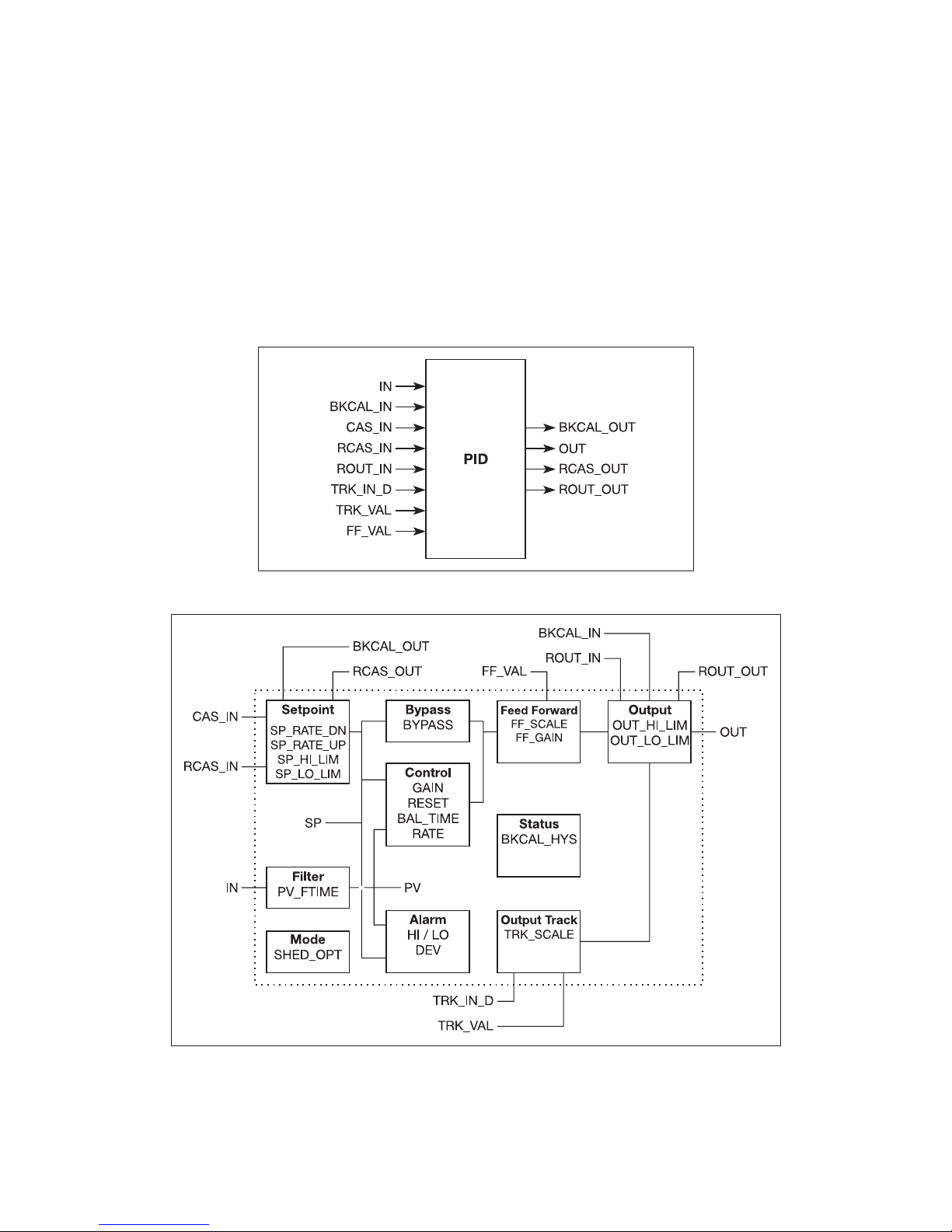
31
4.0 PID Control Block, Fieldbus Foundation
4.1 Introduction:
PR5350 is fitted with a PID Control Block which can only be used in Fieldbus Foundation installations. The PID Block is constructed according to standard specifications outlined in
Fieldbus Foundation and producer specific parameters have not been added. Please notice that
the PID function is not specified in the Profibus Nutzerorganisation and thus cannot be used in
Profibus installations.
4.2 Overview
The PID block is key to many control schemes and is used almost universally, with the exception of PD, which is used when the process itself does the integration. As long as an error
exists, the PID function will integrate the error, which moves the output in a direction to correct the error. PID blocks may be cascaded when the dierence in process time constants of a
primary and secondary process measurement makes it necessary or desirable.
4.3 Schematic:
4.4 Description
The Process Value to be controlled is connected to the IN input. This value is passed through
a filter whose time constant is PV_FTIME. The value is then shown as the PV, which is used in
conjunction with the SP in the PID algorithm. A PID will not integrate if the limit status of IN is
constant. A full PV and DV alarm sub-function is provided. The PV has a status, although it is a
Contained parameter.
Page 32

32
This status is a copy of IN’s status unless IN is good and there is a PV or block alarm.
The full cascade SP sub-function is used, with rate and absolute limits. There are additional
control options which will cause the SP value to track the PV value when the block is in an actual mode of IMan, LO, Man or ROut. Limits do not cause SP-PV tracking.
There is a switch for BYPASS, which is available to the operator if the Bypass Enable control
option is true. Bypass is used in secondary cascade controllers that have a bad PV. The Bypass
Enable option is necessary because not all cascade control schemes will be stable if BYPASS is
true. BYPASS can only be changed when the block mode is Man or O/S. While it is set, the value
of SP, in percent of range, is passed directly to the target output, and the value of OUT is used
for BKCAL_OUT. When the mode is changed to Cas, the upstream block is requested to initialize to the value of OUT. When a block is in Cas mode, then on the transition out of bypass, the
upstream block is requested to initialize to the PV value, regardless of the »Use PV for BKCAL_
OUT« option.
GAIN, RESET, and RATE are the tuning constants for the P, I, and D terms, respectively. Gain is
a dimensionless number. RESET and RATE are time constants expressed in seconds. There are
existing controllers that are tuned by the inverse value of some or all of them, such as proportional band and repeats per minute. The human interface to these parameters should be able
to display the user’s preference. The Direct Acting control option, if true, causes the output to
increase when the PV exceeds the SP. If false, the output will decrease when the PV exceeds
the SP. It will make the dierence between positive and negative feedback, so it must be set
properly, and never changed while in an automatic mode. The setting of the option must also
be used in calculating the limit state for BKCAL_OUT.
The output supports the feed forward algorithm. The FF_VAL input brings in an external value
which is proportional to some disturbance in the control loop. The value is converted to percent of output span using the values of parameter FF_SCALE. This value is multiplied by the
FF_GAIN and added to the target output of the PID algorithm. If the status of FF_VAL is Bad,
the last usable value will be used, because this prevents bumping the output. When the status
returns to good, the block will adjust its integral term to maintain the previous output.
The output supports the track algorithm.
There is an option to use either the SP value after limiting or the PV value for the BKCAL_OUT
value..
4.5 Supported Modes
O/S, IMan, LO, Man, Auto, Cas, RCas, and ROut.
4.6 Alarm Types
Standard block alarm plus standard HI_HI, HI, DV_HI, DV_LO, LO, and LO_LO alarms applied to
PV.
4.7 Mode Handling
Standard transition in and out of O/S.
4.8 Status Handling
Standard, plus the following things for the control selector If Not selected is received at
BKCAL_IN, the PID algorithm should make necessary adjustments to prevent windup.
4.9 Initialization
Standard.
Page 33

33
4.10 PID Control Block Parameter List
Parameter
Rel.
Index
Description Type Store
Size
byte
RO /
R/W
Min. Max. Default
ST_REV
1
The revision level of the static data associated with the function block. To support tracking changes in static para meter
attributes, the associated block’s static revision parameter
will be incremented each time a static parameter attribute
value is changed. Also, the associated block’s static revision
parameter may be incremented if a static para meter attribute
is written but the value is not changed.
Un-
signed 16SRC 2 RO 0
TAG_DESC
2 The user description of the intended application of the block.
Octet
String
SRC 32 R/W spaces
STRATEGY
3
The strategy field can be used to identify grouping of blocks.
This data is not checked or processed by the block.
Un-
signed 16SRC 2 R/W 0
ALERT_KEY
4
Contains the identification number of the plant unit. It helps
to identify the location (plant unit) of an event.
Un-
signed 8SRC 1 R/W 1 255 0
MODE_BLK
5
Contains the current mode and the permitted and normal
mode of the block.
DS-69 Mix 4 Mix O/S
BLOCK_ERR
6
This parameter reflects the error status associated with the
hardware or software components associated with a block. It
is a bit string, so that multiple errors may be shown.
Bit
String
D 2 RO
PV
7
Either the primary analog value for use in executing the
function, or a process value associated with it. May also be
calculated from the READBACK value of an AO block.
DS-65 D 5 RO
SP
8 The analog setpoint of this block. DS-65 N 5 R/W
PV_SCALE
±10%
OUT
9
The primary analog value calculated as a result of executing
the function.
DS-65 N 5 R/W
OUT_SCALE
±10%
PV_SCALE
10
The high and low scale values, engineering units code, and
number of digits to the right of the decimal point to be used
in displaying the PV parameter and parameters which have
the same scaling as PV.
DS-68 SRC 11 R/W 0-100%
OUT_SCALE
11
The high and low scale values, engineering units code, and
number of digits to the right of the decimal point to be used
in displaying the OUT parameter and parameters which have
the same scaling as OUT.
DS-68 SRC 11 R/W 0-100%
GRANT_DENY
12
Options for controlling access of host computer and local
control panels to operating, tuning and alarm parameters of
the block.
DS-70 SRC 2 R/W
CONTROL_OPTS
13
Options which the user may select to alter the calculations
done in a control block.
Bit
String
SRC 2 R/W 0
STATUS_OPTS
14
Options which the user may select in the block processing of
status.
Bit
String
SRC 2 R/W 0
IN
15
The primary input value of the block, required for blocks that
filter the input to get the PV.
DS-65 N 5 R/W
PV_FTIME
16
Time constant of a single exponential filter for the PV, in
seconds.
Float SRC 4 R/W Positive 0
BYPASS
17
The normal control algorithm may be bypassed through this
parameter. When bypass is set, the setpoint value (in percent)
will be directly transferred to the output. To prevent a bump
on transfer to/from bypass, the setpoint will automatically be
initialized to the output value or process variable, respectively, and the path broken flag will be set for one execution.
Un-
signed 8SRC 1 R/W 1 2 0
CAS_IN
18
This parameter is the remote setpoint value, which must
come from another Fieldbus block, or a DCS block through a
defined link.
DS-65 N 5 R/W
SP_RATE_DN
19
Ramp rate at which downward setpoint changes are acted
on in Auto mode, in PV units per second. If the ramp rate is
set to zero, then the setpoint will be used immediately. For
control blocks, rate limiting will apply only in Auto. For output
blocks, rate limiting will apply in Auto, Cas, and RCas modes.
Float SRC 4 R/W Positive +INF
SP_RATE_UP
20
Ramp rate at which upward setpoint changes are acted on in
Auto mode, in PV units per second. If the ramp rate is set to
zero, then the setpoint will be used immediately. For control
blocks, rate limiting will apply only in Auto. For output blocks,
rate limiting will apply in Auto, Cas, and RCas modes.
Float SRC 4 R/W Positive +INF
SP_HI_LIM
21
The setpoint low limit is the lowest setpoint operator entry
that can be used for the block.
Float SRC 4 R/W
PV_SCALE
±10%
100
SP_LO_LIM
22
The setpoint high limit is the highest setpoint operator entry
that can be used for the block.
Float SRC 4 R/W
PV_SCALE
±10%
0
Parameter
Rel.
Index
Description Type Store
Size
byte
RO /
R/W
Min. Max. Default
GAIN
23
Dimensionless value used by the block algorithm in calculating the block output.
Float SRC 4 R/W 0
Page 34

34
RESET
24 The integral time constant, in seconds per repeat. Float SRC 4 R/W Positive +INF
BAL_TIME
25
This specifies the time for the internal working value of bias
or ratio to return to the operator set bias or ratio, in seconds.
In the PID block, it may be used to specify the time constant
at which the integral term will move to obtain balance when
the output is limited and the mode is Auto, Cas, or RCas.
Float SRC 4 R/W Positive 0
RAT E
26 Defines the derivative time constant, in seconds. Float SRC 4 R/W Positive 0
BKCAL_IN
27
The value and status from a lower block’s BKCAL_OUT that
is used to prevent reset windup and to initialize the control
loop.
DS-65 N 5 R/W
OUT_HI_LIM
28 Limits the maximum output value. Float SRC 4 R/W
OUT_SCALE
±10%
100
OUT_LO_LIM
29 Limits the minimum output value. Float SRC 4 R/W
OUT_SCALE
±10%
0
BKCAL_HYS
30
The amount that the output must change away from its output limit before the limit status is turned off, expressed as a
percent of the span of the output.
Float SRC 4 R/W 0 50 0.5
BKCAL_OUT
31
The value and status required by an upper block’s BKCAL_IN
so that the upper block may prevent reset windup and provide bumpless transfer to closed loop control.
DS-65 D 5 RO
RCAS_IN
32
Target setpoint and status provided by a supervisory Host to
a analog control or output block.
DS-65 N 5 R/W
ROUT_IN
33
Target output and status provided by a Host to the control
block for use as the output (ROut mode).
DS-65 N 5 R/W
SHED_OPT
34 Defines action to be taken on remote control device timeout.
Un-
signed 8SRC 1 R/W 0
RCAS_OUT
35
Block setpoint and status after ramping - provided to a supervisory Host for back calculation and to allow action to be
taken under limiting conditions or mode change.
DS-65 D 5 RO
ROUT_OUT
36
Block output and status - provided to a Host for back calculation in ROut mode and to allow action to be taken under
limited conditions or mode change.
DS-65 D 5 RO
TRK_SCALE
37
The high and low scale values, engineering units code, and
number of digits to the right of the decimal point, associated
with TRK_VAL.
DS-68 SRC 11 R/W 0-100%
TRK_IN_D
38
This discrete input is used to initiate external tracking of the
block output to the value specified by TRK_VAL.
DS-66 N 2 R/W
TRK_VAL
39
This input is used as the track value when external tracking
is enabled by TRK_IN_D.
DS-65 N 5 R/W
FF_VAL
40 The feed forward value and status. DS-65 N 5 R/W
FF_SCALE
41
The feedforward input high and low scale values, engineering
units code, and number of digits to the right of the decimal
point.
DS-68 SRC 11 R/W 0-100%
FF_GAIN
42
The gain that the feed forward inpt is multiplied by before it
is added to the calculated control output.
Float SRC 4 R/W 0
UPDATE_EVT
43 This alert is generated by any change to the static data. DS-73 D 14 RO
BLOCK_ALM
44
The block alarm is used for all configuration, hardware, connection failure or system problems in the block. The cause
of the alert is entered in the subcode field. The first alert to
become active will set the Active status in the Status attribute. As soon as the Unreported status is cleared by the alert
reporting task, another block alert may be reported without
clearing the Active status, if the subcode has changed.
DS-72 D 13 R/W
ALARM_SUM
45
The current alert status, unacknowledged states, unreported
states, and disabled states of the alarms associated with the
function block.
DS-74 Mix 8 R/W
ACK_OPTION
46
Selection of whether alarms associated with the block will be
automatically acknowledged.
0 = Auto Ack Disabled; 1 = Auto Ack Enabled.
Bit
String
SRC 2 R/W 0 1 0
ALARM_HYS
47
Amount the PV must return within the alarm limits before
the alarm condition clears. Alarm Hysteresis is expressed as a
percent of the PV span.
Float SRC 4 R/W 0 50 0.5
HI_HI_PRI
48 Priority of the high high alarm.
Un-
signed 8SRC 1 R/W 0 15 0
HI_HI_LIM
49 The setting for high high alarm in engineering units. Float SRC 4 R/W
PV_
SCALE
+INF +INF
HI_PRI
50 Priority of the high alarm.
Un-
signed 8SRC 1 R/W 0 15 0
Parameter
Rel.
Index
Description Type Store
Size
byte
RO /
R/W
Min. Max. Default
HI_LIM
51 The setting for high alarm in engineering units. Float SRC 4 R/W
PV_
SCALE
+INF +INF
Page 35

35
LO_PRI
52 Priority of the low alarm.
Un-
signed 8SRC 1 R/W 0 15 0
LO_LIM
53 The setting for the low alarm in engineering units. Float
SRC
4 R/W -INF
PV_
SCALE
-INF
LO_LO_PRI
54 Priority of the low low alarm.
Un-
signed 8SRC 1 R/W 0 15 0
LO_LO_LIM
55 The setting of the low low alarm in engineering units. Float
SRC
4 R/W -INF
PV_
SCALE
-INF
DV_HI_PRI
56 Priority of the high deviation alarm.
Un-
signed 8SRC 1 R/W 0 15 0
DV_HI_LIM
57
The setting of the high deviation alarm limit in engineering
units.
Float SRC 4 R/W 0
PV
span
+INF
DV_LO_PRI
58 Priority of the low deviation alarm.
Un-
signed 8SRC 1 R/W 0 15 0
DV_LO_LIM
59
The setting of the low deviation alarm limit in engineering
units.
Float SRC 4 R/W
-PV
span
0 -INF
HI_HI_ALM
60 The status for high high alarm and its associated time stamp. DS-71 D 16 R/W
HI_ALM
61 The status for high alarm and its associated time stamp. DS-71 D 16 R/W
LO_ALM
62 The status of the low alarm and its associated time stamp. DS-71 D 16 R/W
LO_LO_ALM
63
The status of the low low alarm and its associated time
stamp.
DS-71 D 16 R/W
DV_HI_ALM
64
The status and time stamp associated with the high deviation alarm.
DS-71 D 16 R/W
DV_LO_ALM
65
The status and time stamp associated with the low deviation
alarm.
DS-71 D 16 R/W
Page 36

36
5.0 Link Active Scheduler (LAS)
5.1 Introduction:
PR5350 features a LAS function which is only available in Fieldbus Foundation installations.
Please note that the LAS function has not been specified by the Profibus Nutzerorganisation
and is therefore not available in Profibus installations.
5.2 Overview
5.3 Description
All links have one and only one Link Active Scheduler (LAS). The LAS operates as the bus arbiter for the link. The LAS does the following:
• recognizes and adds new devices to the link.
• removes non-responsive devices from the link.
• distributes Data Link (DL) and Link Scheduling (LS) time on the link. Data Link Time is a
network-wide time periodicallydistributed by the LAS to synchronize all device clocks on
the bus. Link Scheduling time is a link-specific time represented as an oset from Data
Link Time. It is used to indicate when the LAS on each link begins and repeats its schedule. It is used by system management to synchronize function block execution with the
data transfers scheduled by the LAS.
• polls devices for process loop data at scheduled transmission times.
• distributes a priority-driven token to devices between scheduled transmissions.
Any device on the link may become the LAS, as long as it is capable. The devices that are capable of becoming the LAS are called link master devices. All other devices are referred to as
basic devices. When a segment first starts up, or upon failure of the existing LAS, the link master devices on the segment bid to become the LAS. The link master that wins the bid begins
operating as the LAS immediately upon completion of the bidding process. Link masters that
do not become the LAS act as basic devices. However, the link masters can act as LAS backups
by monitoring the link for failure of the LAS and then bidding to become the LAS when a LAS
failure is detected.
Only one device can communicate at a time. Permission to communicate on the bus is controlled by a centralized token passed between devices by the LAS. Only the device with the
token can communicate. The LAS maintains a list of all devices that need access to the bus.
This list is called the “Live List.”
Two types of tokens are used by the LAS. A time-critical token, compel data (CD), is sent by the
LAS according to a schedule. A non-time critical token, pass token (PT), is sent by the LAS to
each device in ascending numerical order according to address.
Page 37

www.prelectronics.fr
sales-fr@prelectronics.com
www.prelectronics.de
sales-de@prelectronics.com
www.prelectronics.es
sales-es@prelectronics.com
www.prelectronics.it
sales-it@prelectronics.com
www.prelectronics.se
sales-se@prelectronics.com
www.prelectronics.com
sales-uk@prelectronics.com
www.prelectronics.com
sales-us@prelectronics.com
www.prelectronics.cn
sales-cn@prelectronics.com
www.prelectronics.be
sales-be@prelectronics.com
Head oce
Denmark www.prelectronics.com
PR electronics A/S sales@prelectronics.dk
Lerbakken 10 tel. +45 86 37 26 77
DK-8410 Rønde fax +45 86 37 30 85
 Loading...