

Page 1

4801
Modbus gateway
Installation and
connection guide
No. 4801V100 - UK
Page 2

(1349)
PR electronics A/S tilbyder et bredt program af analoge og digitale
signalbehandlingsmoduler til industriel automation. Programmet
består af Isolatorer, Displays, Ex-barrierer, Temperaturtransmittere,
Universaltransmittere mfl. Vi har modulerne, du kan stole på i selv
barske miljøer med elektrisk støj, vibrationer og temperaturudsving,
og alle produkter opfylder de strengeste internationale standarder.
Vores motto »Signals the Best« er indbegrebet af denne filosofi – og
din garanti for kvalitet.
PR electronics A/S oers a wide range of analogue and digital
signal conditioning devices for industrial automation. The product
range includes Isolators, Displays, I.S. Interfaces, Temperature
Transmitters, and Universal Devices. You can trust our products in
the most extreme environments with electrical noise, vibrations and
temperature fluctuations, and all products comply with the most
exacting international standards. »Signals the Best« is the epitome
of our philosophy – and your guarantee for quality.
PR electronics A/S ore une large gamme de produits pour le
traite ment des signaux analogiques et numériques dans tous
les domaines industriels. La gamme de produits s’étend des
transmetteurs de température aux acheurs, des isolateurs aux
interfaces SI, jusqu’aux modules universels. Vous pouvez compter
sur nos produits même dans les conditions d’utilisation sévères,
p.ex. bruit électrique, vibrations et fluctuations de température.
Tous nos produits sont conformes aux normes internationales les
plus strictes. Notre devise »SIGNALS the BEST« c’est notre ligne
de conduite - et pour vous l’assurance de la meilleure qualité.
PR electronics A/S verfügt über ein breites Produktprogramm an
analogen und digitalen Signalverarbeitungsmodule für die industrielle Automatisierung. Dieses Programm umfasst Displays,
Temperaturtransmitter, Ex- und galvanische Signaltrenner, und
Universalgeräte. Sie können unsere Geräte auch unter extremen
Einsatzbedingungen wie elektrisches Rauschen, Erschütterungen
und Temperaturschwingungen vertrauen, und alle Produkte von
PR electronics werden in Überein stimmung mit den strengsten
internationalen Normen produziert. »Signals the Best« ist Ihre
Garantie für Qualität!
DK
UK
FR
DE
Page 3

4801V100-UK 1
4801 MODBUS GATEWAY
INSTALLATION AND
CONNECTION GUIDE
CONTENTS
Setting up the 4801 gateway ......................................................................... 2
Change from point to point communication
to LAN communication ................................................................................... 8
Change LAN communication setup
back to point to point communication ..................................................... 12
4801 gateway specifications ........................................................................... 17
Modbus basics ......................................................................................................... 19
Page 4

2 4801 V100-UK
Setting up the
4801 gateway
Page 5
4801V100-UK 3
Setting up the 4801 gateway
A PC or MAC Computer must be used to setup the 4801 gateway.
If you are not able to maintain an internet connection -
while connected to the 4801 gateway - then you have to download a
certificate for your user ID.
A user ID can easily be created by entering www.pps.prelectronics.com
- the only requirement for doing this is to be on the internet.
Web browser requirements for your PC or MAC:
Internet Explore 9 or newer version
Firefox 22 or newer version.
Please note: Firefox must be used as web browser if you are using a PC running Windows XP.
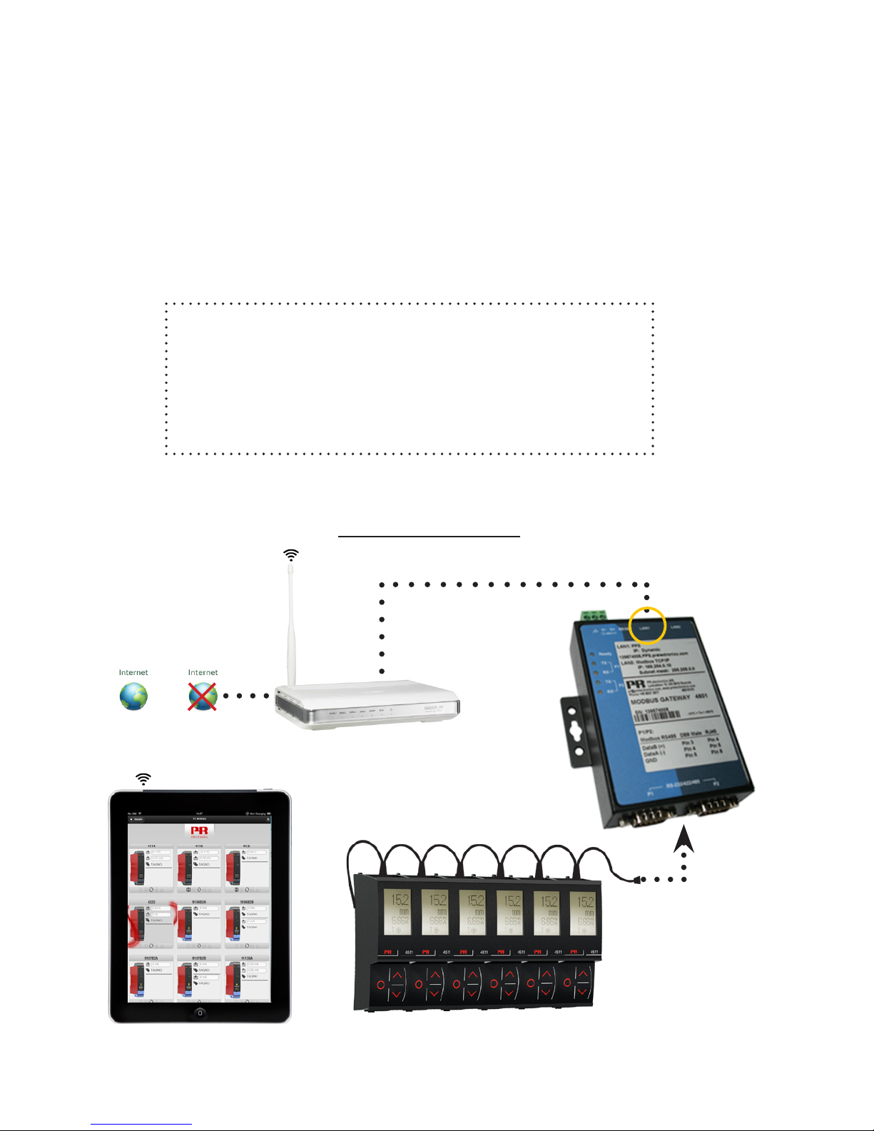
Typical PPS setup:
LAN1
or
Page 6

4 4801 V100-UK
Setting up the 4801 gateway
Enter - www.pps.prelectronics.com
Download and install the plugin -
this by selecting: ”Download Plugin for this Browser”
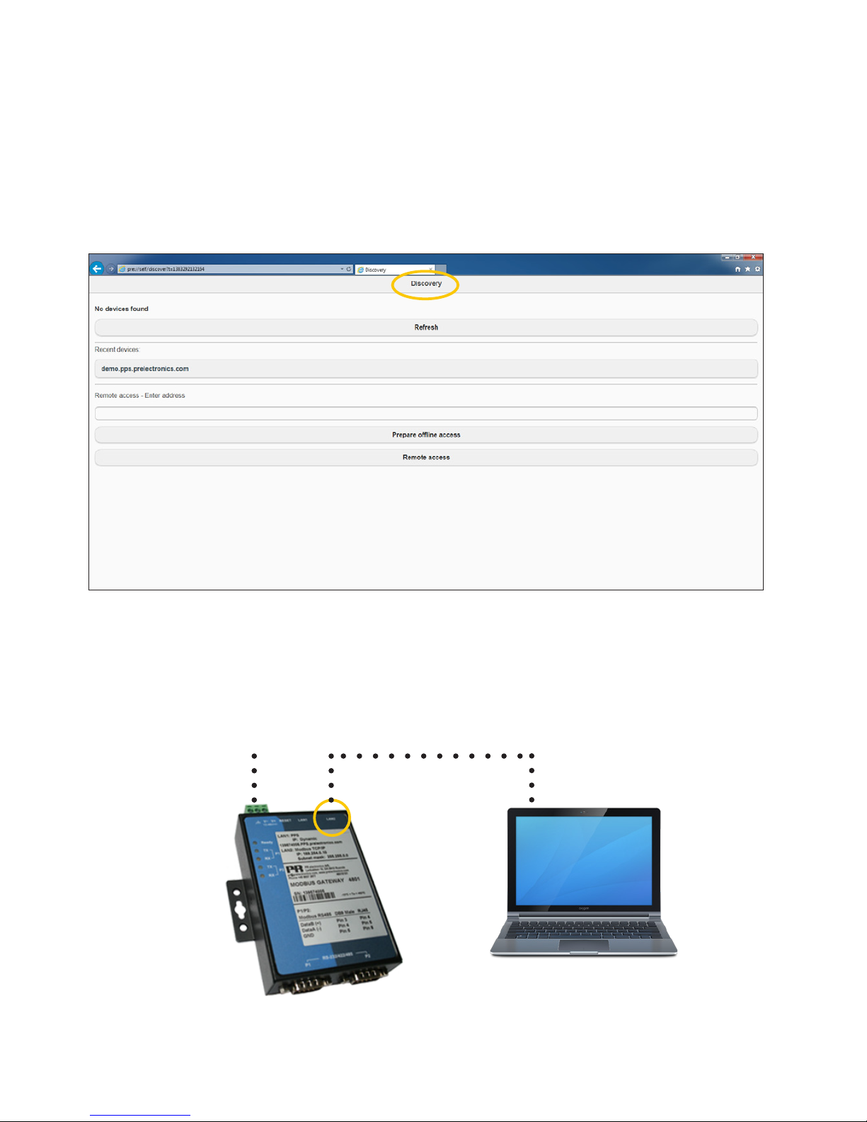
When you have - downloaded the certificate to your Com-
puter, you will be directed to the ”Discovery” view page.
Press this link - to download a plugin certificate for
o-line use, which means setting up the 4801 gateway
without any internet connection.
Page 7
4801V100-UK 5
24 VDC supply
Setting up the 4801 gateway
Save pre://self/discover - on your favorite list for easy future access.
Please make sure - that your Computer IP settings are set to dynamic.
Connect the 4801 gateway LAN2 (general configuration port)
- directly to your Computer by using a standard Ethernet cable.
It may take some minutes - before the connection is established.
LAN2
Page 8

6 4801 V100-UK
Setting up the 4801 gateway
Select the 4801 gateway - from the local device list.
The 4801 gateway seriel number is a part of the device name.
Log in with your user ID - if you do not yet have a user ID, you
have to create one by going to www.pps.prelectronics.com.
Press “Refresh” - to update the list with local found devices.
Page 9

4801V100-UK 7
Setting up the 4801 gateway
It is now possible - to configure the LAN1 and LAN2
ports of the 4801 gateway, and also possible to change
the settings on the Modbus RTU serial ports (P1 and P2).
Port 1 & 2 - Modbus RTU communications
LAN1 - Ethernet for PPS application
LAN2 - TCP/IP Ethernet
Page 10

8 4801 V100-UK
Change from
point to point
communication to
LAN communication
Page 11

4801V100-UK 9
Change from point to point communication
to LAN communication
Enter the ”Discovery” view page - to get here please refer to
the ”Setting up the 4801 gateway” guide found at page 2.
Press “Refresh” - to update the list with available local devices.
Select the 4801 gateway, ”device s/n”-config.pps.prelectronics.com,
from the devices list.
Page 12

10 4801 V100-UK
Change from point to point communication
to LAN communication
Give the 4801 gateway - an available IP address on your local
network. Press “Apply” to acknowledge.
An example:
A Computer on the local network has the following setup:
IP: 192.168.1.126 and Subnet Mask: 255.255.255.0.
Configure the 4801 gateway as the following:
IP: 192.168.1.X - where X is a number between 1 and 255.
(Make sure the number isn’t used by another device).
Subnet Mask: 255.255.255.0
Page 13

4801V100-UK 11
Press “Yes” - to confirm and use the new settings.
The 4801 gateway will now reboot.
Connect the LAN2 port - on the 4801 gateway - to the
local network, by using a standard Ethernet cable.
You can now - use TCP/IP communication from any device,
connected to the local network.
Please note - it is now only possible to access the
configuration via your local network.
Change from point to point communication
to LAN communication
Page 14

12 4801 V100-UK
Change LAN
communication setup
back to
point to point
communication
Page 15

4801V100-UK 13
There are two ways to do this...
Select the 4801 gateway - from the available local devices list.
Method 1 (recommended):
Connect to “pre://self/discover” - in your browser, by using a
Computer connected to the local network.
Press “Refresh” - to update the list with local devices.
Change LAN communication setup
back to point to point communication
Please note:
If no devices appears in the local network list,
please check the Firewall settings for your network.
Page 16

14 4801 V100-UK
Change the IP settings - of the 4801 gateway -
back to default settings, which are:
IP: 169.254.0.10 and Subnet mask: 255.255.0.0
Press “apply” - to accept the changes.
Change LAN communication setup
back to point to point communication
Page 17

4801V100-UK 15
The 4801 gateway - will now reboot.
Connect the LAN2 port - on the 4801 gateway - to the
Computer using an Ethernet cable. You can now use TCP/IP
communication from Computer directly through LAN2.
Please note - It is now only possible to communicate with
the 4801 gateway via TCP/IP by using a direct wired connection to the LAN2 port.
Press “Yes” - to confirm and use the settings.
Change LAN communication setup
back to point to point communication
Page 18

16 4801 V100-UK
Press and activate - the reset button for 10 seconds;
this will restore the settings to default, and clear the
created user list.
After the reset - the 4801 gateway will have the following (default) settings:
IP: 169.254.0.10 and Subnet Mask: 255.255.0.0.
Connect the LAN2 port - on the 4801 gateway - to the
Computer using an Ethernet cable. You can now use TCP/
IP communication from Computer directly through LAN2.
Please note - It is now only possible to communicate
with the 4801 gateway via TCP/IP by using a direct
wired connection to the LAN2 port.
Method 2:
(Only use this method if you can’t find the IP address of the gateway)
Change LAN communication setup
back to point to point communication
Page 19

4801V100-UK 17
4801 gateway
specifications
Page 20

18 4801 V100-UK
TYPE 4801 ................................................................. Modbus Gateway
Applications................................................................ PPS application communications
gateway and Modbus RTU to
Ethernet Modbus TCP/IP gateway.
Specifications:
Supply voltage .......................................................... 12...48 VDC - 4.5 W - max. 340 mA
Operating temperature .......................................... -10...+60 °C
LAN1, RJ45 ................................................................. PPS communication port
”device s/n”.pps.prelectronics.com
- IP: Dynamic
LAN2, RJ45 ................................................................. Modbus TCP/IP - IP: 169.254.0.10 -
Subnet mask: 255.255.0.0
Port 1 and 2, DB9 male ......................................... Modbus RTU over RS - 485
(default baud rate: 57.6k bps)
Upto 32 PR 4511 devices can be
connected directly to each Port.
Accessories................................................................. 2 pcs. of SUB-D9 to RJ45 cables are
included (200 mm) - for conneting
the 4511 devices to the Modbus
RTU P1 and P2 ports.
4801 gateway specifications
Page 21

4801V100-UK 19
Modbus
Basics
Page 22

20 4801 V100-UK
Modbus basics
Modbus is a “master-slave” system,
where the “master” communicates with one or multiple “slaves”.
The master typically is a PLC (Programmable Logic Controller), DCS (Distributed
Control System), HMI (Human Machine Interface), RTU (Remote Terminal Unit)
or PC.
The three most common Modbus versions used are: MODBUS ASCII, MODBUS
RTU and MODBUS/TCP.
In Modbus RTU, data is coded in binary, and requires only one communication
byte per data byte. This is ideal for use over multi-drop RS485 networks,
at speeds up to 115,200 bps. The most common speeds are 9,600 bps and
19,200 bps. Modbus RTU is the most widely used industrial protocol and is
supported by the 4511.
Modbus RTU:
To communicate with a slave device, the master sends a message containing:
Device Address - Function Code - Data - Error Check
The Device Address is a number from 0 to 247.
Messages sent to address 0 (broadcast messages) will be accepted by all slaves, but numbers 1-247 are addresses of specific devices. With the exception
of broadcast messages, a slave device always responds to a Modbus message
so the master knows the message was received.
4511 Supported Modbus Function Codes:
Command Function code
Read Holding Registers 03
Read Input Registers 04
Write Single Register 06
Diagnostics 08
Write Multiple Registers 16
The Function Code defines the command that the slave device is to execute,
such as read data, accept data, report status. Some function codes have subfunction codes.
The Data defines addresses in the device’s memory map for read functions,
contains data values to be written into the device’s memory, or contains other
information needed to carry out the function requested.
The Error Check is a 16-bit numeric value representing the Cyclic Redundancy
Check (CRC).
Page 23

Programmable displays with a wide
selection of inputs and outputs for display of temperature,
volume and weight, etc. Feature linearisation, scaling, and
dierence measurement functions for programming via
PReset software.
Displays
A wide selection of transmitters for DIN
form B mounting and DIN rail devices with analogue
and digital bus communication ranging from applicationspecific to universal transmitters.
Temperature
Galvanic isolators for analogue and digital
signals as well as HART® signals. A wide product range
with both loop-powered and universal isolators featuring
linearisation, inversion, and scaling of output signals.
Isolation
Interfaces for analogue and digital signals
as well as HART® signals between sensors / I/P converters /
frequency signals and control systems in Ex zone 0, 1 & 2
and for some devices in zone 20, 21 & 22.
Ex interfaces
PC or front programmable devices with
universal options for input, output and supply. This range
oers a number of advanced features such as process
calibration, linearisation and auto-diagnosis.
Multifunctional
Page 24

www.prelectronics.fr
sales@prelectronics.fr
www.prelectronics.de
sales@prelectronics.de
www.prelectronics.es
sales@prelectronics.es
www.prelectronics.it
sales@prelectronics.it
www.prelectronics.se
sales@prelectronics.se
www.prelectronics.com
sales@prelectronics.co.uk
www.prelectronics.com
sales@prelectronics.com
www.prelectronics.cn
sales@prelectronics.cn
Head oce
Denmark www.prelectronics.com
PR electronics A/S sales@prelectronics.dk
Lerbakken 10 tel. +45 86 37 26 77
DK-8410 Rønde fax +45 86 37 30 85
 Loading...