

Page 1
Programmable displays with a wide selection of inputs and outputs for display of temperature,
volume and weight, etc. Feature linearisation, scaling,
and difference measurement functions for programming
via PReset software.
Interfaces for analogue and digital
signals as well as HART
®
signals between sensors / I/P
converters / frequency signals and control systems in Ex
zone 0, 1 & 2 and for some modules in zone 20, 21 & 22.
Galvanic isolators for analogue and digital
signals as well as HART
®
signals. A wide product range
with both loop-powered and universal isolators featuring
linearisation, inversion, and scaling of output signals.
PC or front programmable modules with
universal options for input, output and supply. This range
offers a number of advanced features such as process
calibration, linearisation and auto-diagnosis.
A wide selection of transmitters for DIN
form B mounting and DIN rail modules with analogue
and digital bus communication ranging from applicationspecific to universal transmitters.
Displays
Temperature
Isolation
Ex interfaces
Universal
DK
UK
FR
DE
Side 1
Page 11
Page 23
Seite 35
S I G N A L S T H E B E S T
2 2 3 7
T r i p A m p l i f i e r
N o . 2 2 3 7 V 1 0 2 - I N ( 1 0 1 5 )
F r o m s e r . n o . 9 7 0 1 8 5 0 0 1
Page 2

1
GRÆNSEKONTAKT
Type 2237
INDHOLDSFORTEGNELSE
Advarsler . . . . . . . . . . . . . . . . . . . . . . . . . . . . . . . . . . . . . . 2
Sikkerhedsregler . . . . . . . . . . . . . . . . . . . . . . . . . . . . . . . . 3
Overensstemmelseserklæring. . . . . . . . . . . . . . . . . . . . . . 5
Adskillelse af SYSTEM 2200. . . . . . . . . . . . . . . . . . . . . . . 6
Anvendelse . . . . . . . . . . . . . . . . . . . . . . . . . . . . . . . . . . . . 7
Teknisk karakteristik . . . . . . . . . . . . . . . . . . . . . . . . . . . . . 7
Setpunkt . . . . . . . . . . . . . . . . . . . . . . . . . . . . . . . . . . . . . . 7
Elektriske specifikationer. . . . . . . . . . . . . . . . . . . . . . . . . . 8
Bestillingsskema . . . . . . . . . . . . . . . . . . . . . . . . . . . . . . . . 9
Blokdiagram . . . . . . . . . . . . . . . . . . . . . . . . . . . . . . . . . . . 9
Programmering . . . . . . . . . . . . . . . . . . . . . . . . . . . . . . . . . 10
Page 3
2 3
SIKKERHEDSREGLER
DEFINITIONER:
Farlige spændinger er defineret som områderne: 75...1500 Volt DC og 50...1000
Volt AC.
Teknikere er kvalificerede personer, som er uddannet eller oplært til at kunne
udføre installation, betjening eller evt. fejlfinding både teknisk og sikkerhedsmæssigt forsvarligt.
Operatører er personer, som under normal drift med produktet skal indstille og
betjene produktets trykknapper eller potentiometre, og som er gjort bekendt med
indholdet af denne manual.
MODTAGELSE OG UDPAKNING:
Udpak modulet uden at beskadige dette, og sørg for, at manualen altid følger
modulet og er tilgængelig. Indpakningen bør følge modulet, indtil dette er monteret på blivende plads.
Kontrollér ved modtagelsen, at modultypen svarer til den bestilte.
MILJØFORHOLD:
Undgå direkte sollys, kraftigt støv eller varme, mekaniske rystelser og stød, og
udsæt ikke modulet for regn eller kraftig fugt. Om nødvendigt skal opvarmning,
udover de opgivne grænser for omgivelsestemperatur, forhindres ved hjælp af
ventilation.
Alle moduler hører til Installationskategori II, Forureningsgrad 1 og Isolationsklasse II.
INSTALLATION:
Modulet må kun tilsluttes af teknikere, som er bekendte med de tekniske udtryk,
advarsler og instruktioner i manualen, og som vil følge disse.
Hvis der er tvivl om modulets rette håndtering, skal der rettes henvendelse til den
lokale forhandler eller alternativt direkte til:
PR electronics A/S, Lerbakken 10, DK-8410 Rønde tlf: +45 86 37 26 77.
Installation og tilslutning af modulet skal følge landets gældende regler for installation af elektrisk materiel bl. a. med hensyn til ledningstværsnit, for-sikring og
placering.
Beskrivelse af indgang / udgang og forsyningsforbindelser findes på blokdiagrammet og sideskiltet.
ADVARSEL
Dette modul er beregnet for tilslutning til livsfarlige elektriske
spændinger. Hvis denne advarsel ignoreres, kan det føre til alvorlig legemsbeskadigelse eller mekanisk ødelæggelse.
For at undgå faren for elektriske stød og brand skal manualens
sikkerhedsregler overholdes, og vejledningerne skal følges.
De elektriske specifikationer må ikke overskrides, og modulet må
kun benyttes som beskrevet i det følgende.
Manualen skal studeres omhyggeligt, før modulet tages i brug.
Kun kvalificeret personale (teknikere) må installere dette modul.
Hvis modulet ikke benyttes som beskrevet i denne manual, så
forringes modulets beskyttelsesforanstaltninger.
ADVARSEL
For at overholde sikkerhedsafstande må moduler med to indbyggede relæer ikke tilsluttes både farlig og ikke-farlig spænding på
samme moduls relækontakter.
SYSTEM 2200 monteres i sokkel type S3B Releco (bestillingsnummer 7023).
Trekant med udråbstegn: Advarsel / krav. Hændelser der kan føre
til livstruende situationer.
CE-mærket er det synlige tegn på modulets overensstemmelse
med direktivernes krav.
Dobbelt isolation er symbolet for, at modulet overholder ekstra
krav til isolation.
SIGNATURFORKLARING:
ADVARSEL
Der må ikke tilsluttes farlig spænding til modulet, før dette er fastmonteret, og følgende operationer på modulet bør kun udføres i
spændingsløs tilstand og under ESD-sikre forhold:
Adskillelse af modulet for indstilling af omskiftere og jumpere.
Installation, ledningsmontage og -demontage.
Fejlfinding på modulet.
Reparation af modulet og udskiftning af sikringer må kun
foretages af PR electronics A/S.
FARLIG
SPÆNDING
INSTAL-
LATION
GENERELT
Page 4

4 5
For moduler, som er permanent tilsluttet farlig spænding, gælder:
For-sikringens maksimale størrelse er 10 A og skal sammen med en
afbryder placeres let tilgængelig og tæt ved modulet. Afbryderen skal
mærkes således, at der ikke er tvivl om, at den afbryder spændingen
til modulet.
KALIBRERING OG JUSTERING:
Under kalibrering og justering skal måling og tilslutning af eksterne spændinger
udføres i henhold til denne manual, og teknikeren skal benytte sikkerhedsmæssigt korrekte værktøjer og instrumenter.
BETJENING UNDER NORMAL DRIFT:
Operatører må kun indstille eller betjene modulerne, når disse er fast installeret
på forsvarlig måde i tavler el. lignende, så betjeningen ikke medfører fare for liv
eller materiel. Dvs., at der ikke er berøringsfare, og at modulet er placeret, så det
er let at betjene.
RENGØRING:
Modulet må, i spændingsløs tilstand, rengøres med en klud let fugtet med destilleret vand.
ANSVAR:
I det omfang, instruktionerne i denne manual ikke nøje er overholdt, vil kunden
ikke kunne rette noget krav, som ellers måtte eksistere i henhold til den indgåede
salgsaftale, mod PR electronics A/S.
OVERENSSTEMMELSESERKLÆRING
Som producent erklærer
PR electronics A/S
Lerbakken 10
DK-8410 Rønde
hermed at følgende produkt:
Type: 2237
Navn: Grænsekontakt
er i overensstemmelse med følgende direktiver og standarder:
EMC-direktivet 2004/108/EF og senere tilføjelser
EN 61326-1
For specifikation af det acceptable EMC-niveau henvises til modulets
elektriske specifikationer.
Lavspændingsdirektivet 2006/95/EF og senere tilføjelser
EN 61010-1
CE-mærket for overensstemmelse med lavspændingsdirektivet blev tilføjet i
året: 1997
Rønde, 12. april 2010 Kim Rasmussen
Producentens underskrift
Page 5
6 7
GRÆNSEKONTAKT 2237
• Justerbar alarmgrænse
• 300 VA relækontakter
• Programmerbar indgang
• Programmerbar relæfunktion
• 24 VDC forsyning
• Monteres i 11-polet relæsokkel
ANVENDELSE:
Alarmdetektor eller regulator i forbindelse med DC strøm- eller spændingssignaler.
TEKNISK KARAKTERISTIK:
Strøm eller spænding som standardsignaler, programmerbare via interne dipswitche.
Alle signaler refererer til forsynings gnd.
Standard indgangsspænding: se tabel.
Indgangsmodstand: typ. 10 MΩ.
Standard indgangsstrøm: se tabel.
Indgangsmodstand: nom. 50 Ω.
Specielle indgangssignaler udføres efter opgave (se fælles specifikationer).
SETPUNKT:
Potentiometer for indstilling af alarmgrænse er ført ud i kassettens front, og indstillingen dækker hele indgangsområdet (skala 0...100%).
Alarmdetektoren har relæudgang, hvorfra en potentialefri skiftekontakt er til
rådighed. Relæet kan programmeres til at aktivere for stigende eller faldende
indgangssignal.
Ved stigende funktion ligger hysteresen under setpunkt, ved faldende ligger
hysteresen over.
Lysdiode i kassettens front indikerer aktiveret relæ.
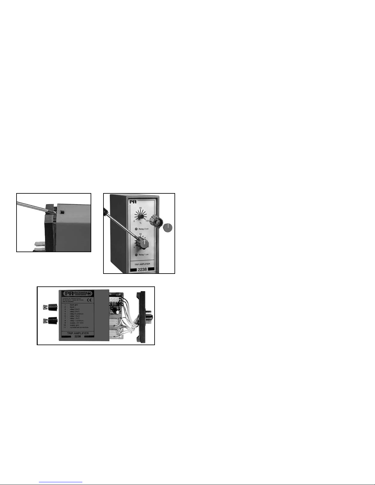
ADSKILLELSE AF SYSTEM 2200
Modulets bagplade frigøres fra huset ved hjælp af en skruetrækker, som vist på
billede 1.
Inden printet kan udtages, kan det ved moduler med knapper være nødvendigt
at fjerne disse, se billede 2.
Derefter kan bagpladen udtrækkes sammen med printet, men vær opmærksom
på printets placering i huset, da det er muligt at isætte dette i flere positioner.
Træk ikke unødigt i ledningerne, men tag fat i printet, se billede 3.
Nu kan switche og jumpere ændres.
Det er vigtigt, at ingen ledninger kommer i klemme, når bagplade og huset
samles.
Billede 1: Adskillelse af bagplade og hus.
Billede 2: Afmontering af knapper.
Billede 3: Udtagelse af print for dipning og flytning af jumpere.
Page 6
8 9
BESTILLINGSSKEMA:
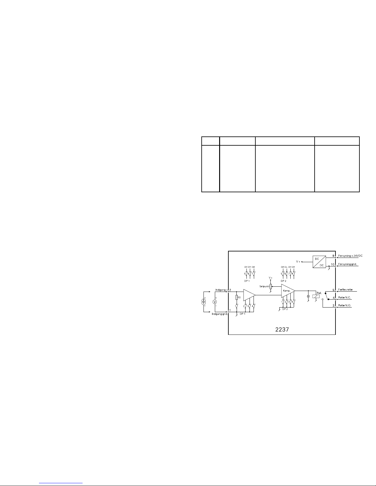
BLOKDIAGRAM:
ELEKTRISKE SPECIFIKATIONER:
Specifikationsområde:
-20°C til +60°C
Fælles specifikationer:
Forsyningsspænding .................................. 19,2...28,8 VDC
Egetforbrug................................................. 0,75 W (relæ trukket)
Isolation, test / drift .................................... 1,4 kVAC / 150 VAC
Skalaoverensstemmelse ............................. Bedre end 5%
Gentagelsesnøjagtighed ............................. Bedre end 0,5%
Hysterese ................................................... 1% standard
Reaktionstid ............................................... Typ. 80 ms
Temperaturkoefficient ................................. < ±0,01% af span / °C
EMC-immunitetspåvirkning ........................ < 1%
Relativ luftfugtighed ................................... < 95% RH (ikke-kond.)
Mål (HxBxD) ............................................... 80,5 x 35,5 x 84,5 mm
Kapslingsklasse .......................................... IP50
Vægt ........................................................... 110 g
Indgang:
Max. måleområde ...................................... 50 mA / 24 VDC
Min. måleområde (span) ............................. 0,8 mA / 800 mVDC
Max. nulpunktsforskydning (offset) ............ 20% af valgt max. værdi
Indgangsmodstand strøm .......................... 50 Ω
Indgangsmodstand spænding ................... Nom. 10 MΩ
Udgang:
Relæudgang:
Max. spænding .......................................... 150 VRMS
Max. strøm ................................................. 2 A / AC
Max. AC effekt ............................................ 300 VA
Max. belastning ved 24 VDC ..................... 1 A
GOST R godkendelse:
VNIIM .......................................................... Se www.prelectronics.dk
Overholdte myndighedskrav: Standard:
EMC 2004/108/EF ...................................... EN 61326-1
LVD 2006/95/EF ......................................... EN 61010-1
Af span = Af det aktuelt valgte område
Type Indgang Udgang Setpunkt
2237 0...20 mA
4...20 mA
0...1 V
0,2...1 V
0...10 V
Speciel
: A
: B
: C
: D
: E
: X
Aktiv for stigende
indgang
Aktiv for faldende
indgang
: 1
: 2
Kærv-funktion
Knap-funktion
: A
: B
Page 7
10 11
TRIP AMPLIFIER
Type 2237
CONTENTS
Warnings . . . . . . . . . . . . . . . . . . . . . . . . . . . . . . . . . . . . . . 12
Safety instructions. . . . . . . . . . . . . . . . . . . . . . . . . . . . . . . 14
Declaration of Conformity . . . . . . . . . . . . . . . . . . . . . . . . . 16
How to dismantle SYSTEM 2200 . . . . . . . . . . . . . . . . . . . 17
Applications. . . . . . . . . . . . . . . . . . . . . . . . . . . . . . . . . . . . 18
Technical characteristics . . . . . . . . . . . . . . . . . . . . . . . . . . 18
Setpoint . . . . . . . . . . . . . . . . . . . . . . . . . . . . . . . . . . . . . . . 18
Electrical specifications. . . . . . . . . . . . . . . . . . . . . . . . . . . 19
Order . . . . . . . . . . . . . . . . . . . . . . . . . . . . . . . . . . . . . . . . . 20
Block diagram . . . . . . . . . . . . . . . . . . . . . . . . . . . . . . . . . . 20
Programming. . . . . . . . . . . . . . . . . . . . . . . . . . . . . . . . . . . 21
PROGRAMMERING:
Indgang og funktion DP1 ON DP2 ON
0...20 mA
4...20 mA
0...1 V
0,2...1 V
0...10 V
2...10 V
Aktivt relæ ved:
Stigende indgangssignal
Faldende indgangssignal
1, 2
1, 3
2
3
2, 4
3, 4
6
6
6
6
6
6
1, 3
2, 4
For sikker drift skal alle andre switche være OFF.
Page 8

12 13
WARNING!
This module is designed for connection to hazardous electric
voltages. Ignoring this warning can result in severe personal
injury or mechanical damage.
To avoid the risk of electric shock and fire, the safety instructions
of this manual must be observed and the guidelines followed.
The electrical specifications must not be exceeded, and the
module must only be applied as described in the following.
Prior to the commissioning of the module, this manual must be
examined carefully.
Only qualified personnel (technicians) should install this module.
If the equipment is used in a manner not specified by the
manufacturer, the protection provided by the equipment may
be impaired.
WARNING!
To keep the safety distances, modules with two built-in relays
must not be connected to both hazardous and non-hazardous
voltages on the same module’s relay contacts.
SYSTEM 2200 must be mounted in socket type S3B Releco
(order no 7023).
SYMBOL IDENTIFICATION
Triangle with an exclamation mark: Warning / demand.
Potentially lethal situations.
The CE mark proves the compliance of the module with
the requirements of the directives.
The double insulation symbol shows that the module is
protected by double or reinforced insulation.
WARNING!
Until the module is fixed, do not connect hazardous voltages to
the module. The following operations should only be carried out
on a disconnected module and under ESD safe conditions:
Dismantlement of the module for setting of DIP-switches
and jumpers.
General mounting, connection and disconnection of wires.
Troubleshooting the module.
Repair of the module and replacement of circuit breakers
must be done by PR electronics A/S only.
GENERAL
HAZARD-
OUS
VOLT AGE
INSTAL-
LATION
Page 9

14 15
The following apply to fixed hazardous voltages-connected modules:
The max. size of the protective fuse is 10 A and, together with a power
switch, it should be easily accessible and close to the module. The
power switch should be marked with a label telling it will switch off the
voltage to the module.
CALIBRATION AND ADJUSTMENT:
During calibration and adjustment, the measuring and connection of external
voltages must be carried out according to the specifications of this manual. The
technician must use tools and instruments that are safe to use.
NORMAL OPERATION:
Operators are only allowed to adjust and operate modules that are safely fixed in
panels, etc., thus avoiding the danger of personal injury and damage. This means
there is no electrical shock hazard, and the module is easily accessible.
CLEANING:
When disconnected, the module may be cleaned with a cloth moistened with
distilled water.
LIABILITY:
To the extent the instructions in this manual are not strictly observed, the customer
cannot advance a demand against PR electronics A/S that would otherwise exist
according to the concluded sales agreement.
SAFETY INSTRUCTIONS
DEFINITIONS:
Hazardous voltages have been defined as the ranges: 75 to 1500 Volt DC, and
50 to 1000 Volt AC.
Technicians are qualified persons educated or trained to mount, operate, and
also troubleshoot technically correct and in accordance with safety regulations.
Operators, being familiar with the contents of this manual, adjust and operate the
knobs or potentiometers during normal operation.
RECEIPT AND UNPACKING:
Unpack the module without damaging it and make sure that the manual always
follows the module and is always available. The packing should always follow the
module until this has been permanently mounted.
Check at the receipt of the module whether the type corresponds to the one
ordered.
ENVIRONMENT:
Avoid direct sunlight, dust, high temperatures, mechanical vibrations and shock,
as well as rain and heavy moisture. If necessary, heating in excess of the stated
limits for ambient temperatures should be avoided by way of ventilation.
All modules fall under Installation Category II, Pollution Degree 1, and Insulation
Class II.
MOUNTING:
Only technicians who are familiar with the technical terms, warnings, and
instructions in the manual and who are able to follow these should connect the
module.
Should there be any doubt as to the correct handling of the module, please
contact your local distributor or, alternatively,
PR electronics A/S, Lerbakken 10, DK-8410 Rønde, Denmark
tel: +45 86 37 26 77.
Mounting and connection of the module should comply with national legislation
for mounting of electric materials, i.e. wire cross section, protective fuse, and
location. Descriptions of Input / Output and supply connections are shown in the
block diagram and side label.
Page 10

16 17
HOW TO DISMANTLE SYSTEM 2200
The back panel of the module is detached from the housing by way of a screwdriver as shown in picture 1.
On a module with knobs, these may have to be removed before the PCB can be
taken out as shown in picture 2.
After this, the back panel can be pulled out together with the PCB, but please
notice the position of the PCB as there is a number of different positions in the
house. Do not pull the wires unnecessarily, instead pull the PCB, see picture 3.
Switches and jumpers can now be moved.
When assembling the back plate and housing, please make sure no wires are
stuck.
DECLARATION OF CONFORMITY
As manufacturer
PR electronics A/S
Lerbakken 10
DK-8410 Rønde
hereby declares that the following product:
Type: 2237
Name: Trip amplifier
is in conformity with the following directives and standards:
The EMC Directive 2004/108/EC and later amendments
EN 61326-1
For specification of the acceptable EMC performance level, refer to the
electrical specifications for the module.
The Low Voltage Directive 2006/95/EC and later amendments
EN 61010-1
The CE mark for compliance with the Low Voltage Directive was affixed in the
year: 1997
Rønde, 12 April 2010 Kim Rasmussen
Manufacturer’s signature
Picture 1: Dismantlement of back plate
and housing.
Picture 2: Removal of knobs.
Picture 3: Removal of PCB for adjustment of DIP-switches
and replacement of jumpers.
Page 11

18 19
TRIP AMPLIFIER 2237
• Adjustable alarm level
• 300 VA relay contacts
• Programmable input
• Programmable relay function
• 24 VDC supply
• For mounting in 11-pole relay socket
APPLICATIONS:
Alarm detector or controller in connection with DC current or voltage signals.
TECHNICAL CHARACTERISTICS:
Current or voltage as standard signals, programmable via internal DIP-switches.
All signals refer to supply ground.
Standard input voltage: See table.
Input resistance: Typ. 10 MΩ.
Standard input current: See table.
Input resistance: Nom. 50 Ω.
Special input signals according to order (see common specifications).
SETPOINT:
Potentiometer for alarm setpoint adjustment is front panel mounted and covers
the entire measurement range (scale 0...100%).
The relay can be programmed to activate for increasing or decreasing input
signal. By increasing function the hysteresis is below the setpoint, by decreasing
above.
A LED in the cassette front plate indicates an activated relay.
ELECTRICAL SPECIFICATIONS:
Specifications range:
-20°C to +60°C
Common specifications:
Supply voltage............................................ 19.2...28.8 VDC
Internal consumption ................................. 0.75 W (relay ON)
Isolation, test / operation ........................... 1.4 kVAC / 150 VAC
Scale accuracy ........................................... Better than 5%
Repetition accuracy ................................... Better than 0.5%
Hysteresis ................................................... 1% standard
Response time ........................................... Typ. 80 ms
Temperature coefficient .............................. < ±0.01% of span / °C
EMC immunity influence ............................ < 1%
Relative humidity ........................................ < 95% RH (non-cond.)
Dimensions (HxWxD) .................................. 80.5 x 35.5 x 84.5 mm
Protection degree ....................................... IP50
Weight ........................................................ 110 g
Input:
Max. measurement range .......................... 50 mA / 24 VDC
Min. measurement range (span)................. 0.8 mA / 800 mVDC
Max. offset.................................................. 20% of selected max. value
Input resistance, current ............................ 50 Ω
Input resistance, voltage ............................ Nom. 10 MΩ
Output:
Relay output:
Max. voltage ............................................... 150 VRMS
Max. current ............................................... 2 A / AC
Max AC power ........................................... 300 VA
Max. load at 24 VDC .................................. 1 A
GOST R approval:
VNIIM .......................................................... See www.prelectronics.com
Observed authority requirements: Standard:
EMC 2004/108/EC ..................................... EN 61326-1
LVD 2006/95/EC ......................................... EN 61010-1
Of span = Of the presently selected range
Page 12

20 21
PROGRAMMING:ORDER:
BLOCK DIAGRAM:
Type Input Output Setpoint
2237 0...20 mA
4...20 mA
0...1 V
0.2...1 V
0...10 V
Special
: A
: B
: C
: D
: E
: X
Active at
increasing input
Active at
decreasing input
: 1
: 2
Setpoint notch
operation
Setpoint knob
operation
: A
: B
Input and function DP1 ON DP2 ON
0...20 mA
4...20 mA
0...1 V
0.2...1 V
0...10 V
2...10 V
Active relay at:
Increasing input signal
Decreasing input signal
1, 2
1, 3
2
3
2, 4
3, 4
6
6
6
6
6
6
1, 3
2, 4
For safe operation, all other switches must be OFF.
Page 13

22 23
RELAIS A SEUIL
Type 2237
SOMMAIRE
Avertissements . . . . . . . . . . . . . . . . . . . . . . . . . . . . . . . . . 24
Consignes de sécurité. . . . . . . . . . . . . . . . . . . . . . . . . . . . 26
Déclaration de conformité . . . . . . . . . . . . . . . . . . . . . . . . . 28
Démontage du SYSTEME 2200 . . . . . . . . . . . . . . . . . . . . 29
Applications. . . . . . . . . . . . . . . . . . . . . . . . . . . . . . . . . . . . 30
Caractéristiques techniques . . . . . . . . . . . . . . . . . . . . . . . 30
Consigne . . . . . . . . . . . . . . . . . . . . . . . . . . . . . . . . . . . . . . 30
Spécifications électriques . . . . . . . . . . . . . . . . . . . . . . . . . 31
Référence de commande . . . . . . . . . . . . . . . . . . . . . . . . . 32
Schéma de principe . . . . . . . . . . . . . . . . . . . . . . . . . . . . . 32
Configuration. . . . . . . . . . . . . . . . . . . . . . . . . . . . . . . . . . . 33
Page 14

24 25
SIGNIFICATION DES SYMBOLES
Triangle avec point d’exclamation : Attention ! Si vous ne
respectez pas les instructions, la situation pourrait être fatale.
Le signe CE indique que le module est conforme aux
exigences des directives.
Ce symbole indique que le module est protégé par une
isolation double ou renforcée.
AVERTISSEMENT !
Ce module est conçu pour supporter une connexion à des
tensions électriques dangereuses. Si vous ne tenez pas compte
de cet avertissement, cela peut causer des dommages corporels
ou des dégâts mécaniques.
Pour éviter les risques d’électrocution et d’incendie, conformezvous aux consignes de sécurité et suivez les instructions
mentionnées dans ce guide. Vous devez vous limiter aux
spécifications indiquées et respecter les instruc tions d’utilisation
de ce module, telles qu’elles sont décrites dans ce guide.
Il est nécessaire de lire ce guide attentivement avant de mettre
ce module en marche. L’installation de ce module est réservée à
un personnel qualifié (techniciens). Si la méthode d’utilisation de
l’équipement diffère de celle décrite par le fabricant, la protection
assurée par l’équipe ment risque d’être altérée.
AVERTISSEMENT !
Afin de conserver les distances de sécurité, les modules à deux
relais intégrés ne doivent pas être mis sous tensions dangereuses
et non dangereuses sur les mêmes contacts du relais du module.
Il convient de monter l’appareil SYSTEM 2200 sur un support du
type S3B Releco (numéro de référence 7023).
AVERTISSEMENT !
Tant que le module n’est pas fixé, ne le mettez par sous tensions
dangereuses.
Les opérations suivantes doivent être effec tuées avec le module
débranché et dans un environnement exempt de décharges
élec trostatiques (ESD) : démontage du module pour régler
les commutateurs DIP et les cavaliers, montage général,
raccordement et débranchement de fils et recherche de pannes
sur le module.
Seule PR electronics SARL est autorisée à réparer le module
et à remplacer les fusibles.
INFOR-
MATIONS
GENERALES
TENSION
DANGE-
REUSE
INSTAL-
LATION
Page 15

26 27
Le montage et le raccordement du module doivent être conformes à la législation
nationale en vigueur pour le montage de matéri aux électriques, par exemple,
diamètres des fils, fusibles de protection et implantation des modules. Les
connexions des alimentations et des entrées / sorties sont décrites dans le
schéma de principe et sur l’étiquette de la face latérale du module.
Les instructions suivantes s’appliquent aux modules fixes connectés en tensions
dangereu ses :
Le fusible de protection doit être de 10 A au maximum. Ce dernier, ainsi que
l’interrupteur général, doivent être facilement accessibles et à proximité du
module. Il est recommandé de placer sur l’interupteur général une étiquette
indiquant que ce dernier mettra le module hors tension.
ETALONNAGE ET REGLAGE
Lors des opérations d’étalonnage et de réglage, il convient d’effectuer les mesures
et les connexions des tensions externes en respectant les spécifications
mentionnées dans ce guide.
Les techniciens doivent utiliser des outils et des instruments pouvant être
manipulés en toute sécurité.
MANIPULATIONS ORDINAIRES
Les opérateurs sont uniquement autorisés à régler et faire fonctionner des modules
qui sont solidement fixés sur des platines des tableaux, ect., afin d’écarter les
risques de dommages corporels. Autrement dit, il ne doit exister aucun danger
d’électrocution et le module doit être facilement accessible.
MAINTENANCE ET ENTRETIEN
Une fois le module hors tension, prenez un chiffon imbibé d’eau distillée pour
le nettoyer.
LIMITATION DE RESPONSABILITE
Dans la mesure où les instructions de ce guide ne sont pas strictement
respectées par le client, ce dernier n’est pas en droit de faire une réclamation
auprès de PR electronics SARL, même si cette dernière figure dans l’accord de
vente conclu.
CONSIGNES DE SECURITE
DEFINITIONS
Les gammes de tensions dangereuses sont les suivantes : de 75 à 1500 Vcc et de
50 à 1000 Vca. Les techniciens sont des person nes qualifiées qui sont capables
de monter et de faire fonc tionner un appareil, et d’y rechercher les pannes, tout
en respectant les règles de sécurité. Les opérateurs, connaissant le contenu de
ce guide, règlent et actionnent les boutons ou les potentiomètres au cours des
manipulations ordinaires.
RECEPTION ET DEBALLAGE
Déballez le module sans l’endommager. Le guide doit toujours être disponible
et se trouver à proximité du module. De même, il est recommandé de conserver
l’emballage du module tant que ce dernier n’est pas définitivement monté. A la
réception du module, vérifiez que le type de module reçu correspond à celui que
vous avez commandé.
ENVIRONNEMENT
N’exposez pas votre module aux rayons directs du soleil et choisissez un endroit
à humidité modérée et à l’abri de la poussière, des températures élevées, des
chocs et des vibrations mécaniques et de la pluie. Le cas échéant, des systèmes
de ventilation permettent d’éviter qu’une pièce soit chauffée au-delà des limites
prescrites pour les températures ambiantes.
Tous les modules appartiennent à la catégorie d’installation Il, au degré de
pollution 1 et à la classe d’isolation Il.
MONTAGE
Il est conseillé de réserver le raccordement du module aux techniciens qui
connaissent les termes techniques, les avertis sements et les instructions de ce
guide et qui sont capables d’appliquer ces dernières.
Si vous avez un doute quelconque quant à la manipulation du module, veuillez
contacter votre distributeur local. Vous pouvez également vous adresser à PR
electronics SARL, Zac du Chêne, Activillage, 4, allée des Sorbiers, F-69673 Bron
Cedex (tél. : (0) 472 140 607) ou à PR electronics A/S, Lerbakken 10, DK-8410
Rønde, Danemark (tél.:+45 86 37 26 77).
Page 16

28 29
DEMONTAGE DU SYSTEME 2200
A l’aide d’un tournevis, dégagez la face arrière du module du boîtier (voir figure 1).
Sur un module équipé de boutons, il faut retirer ces derniers pour pouvoir extraire
la carte à circuits imprimés (voir figure 2).
Vous pouvez maintenant extraire la face a rrière du module ainsi que la carte
à circuits imprimés. Veuillez repérer la position de cette carte car il existe de
nombreuses positions possibles dans le boîtier. Lorsque vous extrayez la carte à
circuits imprimés, tirez sur celle-ci et évitez de tirer sur les fils (voir figure 3).
Vous pouvez maintenant déplacer les commutateurs et les cavaliers. Lorsque
vous assemblez la face arrière du module et le boîtier, veuillez vérifier que les fils
ne sont pas coincés.
DECLARATION DE CONFORMITE
En tant que fabricant
PR electronics A/S
Lerbakken 10
DK-8410 Rønde
déclare que le produit suivant :
Type : 2237
Nom : Relais à seuil
correspond aux directives et normes suivantes :
La directive CEM (EMC) 2004/108/CE et les modifications subséquentes
EN 61326-1
Pour une spécification du niveau de rendement acceptable CEM (EMC)
se référer aux spécifications électriques du module.
La directive basse tension 2006/95/CE et les modifications subséquentes
EN 61010-1
La marque CE pour conformité avec la directive basse tension a été apposée
en 1997
Rønde, le 12 avril 2010 Kim Rasmussen
Signature du fabricant
Figure 1 : Séparation de la face arrière
et du boîtier.
Figure 2 : Retrait des boutons.
Figure 3 : Extraction de la carte à circuits imprimès pour le
réglage des commutateurs et le remplacement des cavaliers.
Page 17

30 31
SPECIFICATIONS ELECTRIQUES :
Plage de température :
-20°C à +60°C
Spécifications communes :
Tension d’alimentation ............................... 19,2...28,8 Vcc
Consommation interne ............................... 0,75 W (relais actif)
Tension d’isolation test / opération ............ 1,4 kVca / 150 Vca
Précision d’échelle ..................................... Mieux que 5%
Précision de répétition ............................... Mieux que 0,5%
Hystérésis ................................................... 1% standard
Temps de réponse ...................................... 80 ms
Coefficient de température......................... < ±0,01% de l’EC/°C
CEM (EMC) : Effet de l’immunité ............... < ±1% de l’EC
Humidité rélative ........................................ < 95% HR (sans cond.)
Dimensions (HxLxP) ................................... 80,5 x 35,5 x 84,5 mm
Degré de protection (boîtier) ...................... IP50
Poids ......................................................... 110 g
Entrée :
Gamme de mesure max. ............................ 50 mA / 24 Vcc
Gamme de mesure min. (échelle) .............. 0,8 mA / 800 mVcc
Décalage max............................................. 20% de la valeur max. sélectionnée
Impédance d’entrée courant ...................... 50 Ω
Impédance d’entrée tension ...................... Nom. 10 MΩ
Sortie :
Sortie relais :
Tension ....................................................... Max. 150 VRMS
Courant ....................................................... Max. 2 A / ca
Puissance ca .............................................. Max. 300 VA
Charge à 24 Vcc ......................................... Max. 1A
Approbation GOST R :
VNIIM .......................................................... Voir www.prelectronics.fr
Agréments et homologations : Standard :
CEM (EMC) 2004/108/CE .......................... EN 61326-1
DBT 2006/95/CE ........................................ EN 61010-1
EC = Echelle configurée
RELAIS A SEUIL
2237
• Un seuil réglable
•
Pouvoir de coupure 300 VA
•
Entrée configurable
•
Fonction relais configurable
•
Alimentation 24 Vcc
•
Embase standard 11 pôles
APPLICATIONS :
Détecteur d’alarme ou régulateur tout ou rien à partir d’un signal analogique
tension ou courant.
CARACTERISTIQUES TECHNIQUES :
Entrée :
Signaux standards tension ou courant configurables avec commutateurs
in ternes. Tous les signaux se réfèrent à la masse de l’alimentation.
Entrée tension : Suivant le tableau.
Impédance d’entrée : Typ. 10 MΩ.
Entrée courant : Suivant le tableau.
Impédance d’entrée : Nom. 50 Ω.
Des gammes spécifiques peuvent être configurées selon vos spécifications (voir
spécifications électriques).
CONSIGNE :
Un potentiomètre monté en face avant permet de regler le seuil d’alarme sur
toute la gamme d’entrée (Echelle : 0...100%).
La sortie relais a un contact libre de potentiel. Le relais peut être configuré avec
une action croissante ou décroissante. Avec une action croissante l’hystérésis est
en-dessous de la consigne, et avec une action décroissante l’hysterésis est audessus de la consigne. Une LED en face avant indique si le relais est actif.
Page 18

32 33
CONFIGURATION :
REFERENCE DE COMMANDE :
SCHEMA DE PRINCIPE :
Type Entrée Sortie Consigne
2237 0...20 mA
4...20 mA
0...1 V
0,2...1 V
0...10 V
Spéc.
: A
: B
: C
: D
: E
: X
Active pour
l’entrée croissante
Active pour
l’entrée décroissante
: 1
: 2
Consigne vis
Cons. bouton
: A
: B
Entrée et fonction DP1 ON DP2 ON
0...20 mA
4...20 mA
0...1 V
0,2...1 V
0...10 V
2...10 V
Relais actif pour :
Signal d’entrée croissante
Signal d’entrée décroissante
1, 2
1, 3
2
3
2, 4
3, 4
6
6
6
6
6
6
1, 3
2, 4
Pour plus de sûreté, les autres commutateurs doivent être
en postition OFF.
Page 19

34 35
GRENZWERTSCHALTER
TYP 2237
INHALTSVERZEICHNIS
Warnung . . . . . . . . . . . . . . . . . . . . . . . . . . . . . . . . . . . . . . 36
Sicherheitsregeln. . . . . . . . . . . . . . . . . . . . . . . . . . . . . . . . 38
Konformitätserklärung. . . . . . . . . . . . . . . . . . . . . . . . . . . . 40
Zerlegung des SYSTEMs 2200. . . . . . . . . . . . . . . . . . . . . 41
Anwendung . . . . . . . . . . . . . . . . . . . . . . . . . . . . . . . . . . . . 42
Technische Merkmale . . . . . . . . . . . . . . . . . . . . . . . . . . . . 42
Sollwert . . . . . . . . . . . . . . . . . . . . . . . . . . . . . . . . . . . . . . . 42
Elektrische Daten . . . . . . . . . . . . . . . . . . . . . . . . . . . . . . . 43
Bestellangaben . . . . . . . . . . . . . . . . . . . . . . . . . . . . . . . . . 44
Blockdiagramm . . . . . . . . . . . . . . . . . . . . . . . . . . . . . . . . . 44
Programmierung . . . . . . . . . . . . . . . . . . . . . . . . . . . . . . . . 45
Page 20

36 37
ZEICHENERKLÄRUNGEN:
Dreieck mit Ausrufungszeichen: Warnung / Vorschrift.
Vorgänge, die zu lebensgefähr lichen Situationen führen können.
Die CE-Marke ist das sichtbare Zeichen dafür, dass das
Modul die Vorschriften erfüllt.
Doppelte Isolierung ist das Symbol dafür, dass das
Modul besondere Anforderungen an die Isolierung erfüllt.
WARNUNG!
Dieses Modul ist für den Anschluss an lebensgefährliche elektrische Spannungen gebaut. Missachtung dieser Warnung kann zu
schweren Verletzungen oder mechanischer Zerstörung führen.
Um eine Gefährdung durch Stromstöße oder Brand zu vermeiden
müssen die Sicher heitsregeln des Handbuches eingehalten, und
die Anweisungen befolgt werden.
Die Spezifikationswerte dürfen nicht überschritten werden, und
das Modul darf nur gemäß folgender Beschreibung benutzt werden. Das Handbuch ist sorgfältig durch zulesen, ehe das Modul in
Gebrauch genommen wird. Nur qualifizierte Personen (Techniker)
dürfen dieses Modul installieren.
Wenn das Modul nicht wie in diesem Handbuch beschrieben
benutzt wird, werden die Schutzeinrichtungen des Moduls
be einträchtigt.
WARNUNG!
Zur Einhaltung der Sicherheitsabstände dürfen Module mit zwei
eingebauten Relaisein heiten nicht sowohl an gefährliche und
ungefährliche Spannung über die selben Relaiskontakte des
Moduls angeschlossen werden.
Das System 2200 wird in einen Sockel vom Typ S3B Releco
(Bestellnummer 7023) montiert.
WARNUNG!
Vor dem abgeschlossenen festen Einbau des Moduls darf daran
keine gefährliche Spannung angeschlossen werden, und folgende
Maßnahmen sollten nur in spannungslo sem Zustand des Moduls
und unter ESD-sicheren Verhältnisse durchgeführt werden:
Öffnen des Moduls zum Einstellen von Umschaltern und Überbrückern.
Installation, Montage und Demontage von Leitungen.
Fehlersuche im Modul.
Reparaturen des Moduls und Austausch von Sicherungen
dürfen nur von PR electronics A/S vorgenommen werden.
ALLGE-
MEINES
GEFÄHR-
LICHE
SPANNUNG
INSTAL-
LATION
Page 21

38 39
Die Installation und der Anschluss des Moduls haben in Übereinstimmung mit
den geltenden Regeln des jeweiligen Landes bez. der Installation elektrischer
Apparaturen zu erfolgen, u.a. bezüglich Leitungsquerschnitt, (elektrischer) VorAbsicherung und Positionierung.
Eine Beschreibung von Eingangs- / Ausgangs- und Versorgungsanschlüssen
befindet sich auf dem Blockschaltbild und auf dem seitlichen Schild.
Für Module, die dauerhaft an eine gefährliche Spannung angeschlossen sind,
gilt:
Die maximale Größe der Vorsicherung beträgt 10 A und muss zusammen mit einem Unterbrecherschalter leicht zugänglich und nahe am
Modul angebracht sein. Der Unterbrecherschalter soll derart gekennzeichnet sein, dass kein Zweifel darüber bestehen kann, dass er die
Spannung für das Modul unterbricht.
KALIBRIERUNG UND JUSTIERUNG:
Während der Kalibrierung und Justierung sind die Messung und der Anschluss
externer Spannungen entsprechend diesem Handbuch auszuführen, und der
Techniker muss hierbei sicherheitsmäßig einwandfreie Werkzeuge und Instrumente benutzen.
BEDIENUNG IM NORMALBETRIEB:
Das Bedienungspersonal darf die Module nur dann einstellen oder bedienen,
wenn diese auf vertretbare Weise in Schalttafeln o. ä. fest installiert sind, so dass
die Bedienung keine Gefahr für Leben oder Material mit sich bringt. D. h., es darf
keine Gefahr durch Berührung bestehen, und das Modul muss so plaziert sein,
dass es leicht zu bedienen ist.
REINIGUNG:
Das Modul darf in spannungslosem Zustand mit einem Lappen gereinigt werden,
der mit destilliertem Wasser leicht angefeuchtet ist.
HAFTUNG:
In dem Umfang, in welchem die Anweisungen dieses Handbuches nicht genau
eingehal ten werden, kann der Kunde PR electronics gegenüber keine Ansprüche
geltend machen, welche ansonsten entsprechend der eingegangenen Verkaufsvereinbarungen existieren können.
SICHERHEITSREGELN
DEFINITIONEN:
Gefährliche Spannungen sind definitionsgemäß die Bereiche: 75...1500 Volt
Gleichspannung und 50...1000 Volt Wechselspannung.
Techniker sind qualifizierte Personen, die dazu ausgebildet oder angelernt sind,
eine Installation, Bedienung oder evtl. Fehlersuche auszuführen, die sowohl
technisch als auch sicherheitsmäßig vertretbar ist.
Bedienungspersonal sind Personen, die im Normalbetrieb mit dem Produkt die
Drucktasten oder Potentiometer des Produktes einstellen bzw. bedienen und die
mit dem Inhalt dieses Handbuches vertraut gemacht wurden.
EMPFANG UND AUSPACKEN:
Packen Sie das Modul aus, ohne es zu beschädigen und sorgen Sie dafür, dass
das Handbuch stets in der Nähe des Moduls und zugänglich ist.
Die Verpackung sollte beim Modul bleiben, bis dieses am endgültigen Platz
montiert ist.
Kontrollieren Sie beim Empfang, ob der Modultyp Ihrer Bestellung entspricht.
UMGEBUNGSBEDINGUNGEN:
Direkte Sonneneinstrahlung, starke Staubentwicklung oder Hitze, mechanische
Erschüt terungen und Stöße sind zu vermeiden; das Modul darf nicht Regen
oder starker Feuchtigkeit ausgesetzt werden. Bei Bedarf muss eine Erwärmung,
welche die an gegebenen Grenzen für die Umgebungstemperatur überschreitet,
mit Hilfe eines Kühlgebläses verhindert werden.
Alle Module gehören der Installationskategorie II, dem Verschmutzungsgrad 1
und der Isolationsklasse II an.
INSTALLATION:
Das Modul darf nur von Technikern angeschlossen werden, die mit den technischen Ausdrücken, Warnungen und Anweisungen im Handbuch vertraut sind
und diese befolgen.
Sollten Zweifel bezüglich der richtigen Handhabung des Moduls bestehen,
sollte man mit dem Händler vor Ort Kontakt aufnehmen. Sie können aber auch
direkt mit PR electronics GmbH, Im Erlengrund 26, D-46149 Oberhausen,
(Tel.: (0) 208 62 53 09-0) oder mit PR electronics A/S, Lerbakken 10,
DK-8410 Rønde, Dänemark (Tel. : +45 86 37 26 77) Kontakt aufnehmen.
Page 22

40 41
ZERLEGUNG DES SYSTEMS 2200
Die hintere Abdeckplatte des Moduls wird vom Gehäuse mit Hilfe eines
Schraubendre hers gelöst, wie im Abb. 1 dargestellt.
Bei Modulen mit Drehknöpfen kann es notwendig werden, diese zu entfernen,
ehe man die Platine herausnehmen kann (siehe Abb. 2).
Danach kann die hintere Abdeckung zusammen mit der Platine herausgezogen
werden, jedoch beachte man die Positionierung der Platine im Gehäuse, da es
möglich ist, sie in mehreren Stellungen einzusetzen. Unnötiges Ziehen an den
Leitungen ist zu vermeiden; ziehen Sie an der Platine (siehe Abb. 3).
Jetzt können Schalter und Überbrücker verändert werden.
Es ist wichtig, dass keine Leitungen eingeklemmt werden, wenn die hintere
Abdeckplatte und das Gehäuse zusammengefügt werden.
KONFORMITÄTSERKLÄRUNG
Als Hersteller bescheinigt
PR electronics A/S
Lerbakken 10
DK-8410 Rønde
hiermit für das folgende Produkt:
Typ: 2237
Name: Grenzwertschalter
die Konformität mit folgenden Richtlinien und Normen:
Die EMV Richtlinien 2004/108/EG und nachfolgende Änderungen
EN 61326-1
Zur Spezifikation des zulässigen Erfüllungsgrades, siehe die Elektrische Daten
des Moduls.
Die Niederspannungsrichtlinien 2006/95/EG und nachfolgende Änderungen
EN 61010-1
Die CE Marke für Konformität mit den Niederspannungsrichtlinien wurde im
Jahre 1997 hinzugefügt.
Rønde, 12. April 2010 Kim Rasmussen
Unterschrift des Herstellers
Abb. 1: Lösen der hinteren Abdeckplatte vom Gehäuse.
Abb.2: Entfernen von Drehknöpfen.
Abb. 3: Herausnehmen der Platine zur Veränderung von
Schaltern und Überbrückern.
Page 23

42 43
ELEKTRISCHE DATEN:
Umgebungstemperatur:
-20°C bis +60°C
Allgemeine Daten:
Versorgungsspannung ................................ 19,2...28,8 VDC
Eigenverbrauch .......................................... 0,75 W (gezogenes Relais)
Isolation Test / Betrieb ............................... 1,4 kVAC / 150 VAC
Skalenübereinstimmung ............................. Besser als 5%
Wiederholungsgenauigkeit ......................... Besser als 0,5%
Hysterese ................................................... 1% Standard
Ansprechzeit ............................................... Typ. 80 ms
Temperaturkoeffizient ................................. < ±0,01% d. Messspanne /°C
EMV-Immunitätseinfluss ............................. < 1%
Relative Luftfeuchtigkeit ............................. < 95% RF (nicht kond.)
Abmessungen (HxBxT) ............................... 80,5 x 35,5 x 84,5 mm
Schutzart .................................................... IP50
Gewicht ...................................................... 110 g
Eingang:
Max. Messbereich ...................................... 50 mA / 24 VDC
Min. Messbereich (Spanne) ........................ 0,8 mA / 800 mVDC
Max. Nullpunktverschiebung (Offset) ......... 20% des gewählten Maximalwertes
Eingangswiderstand Strom ........................ 50 Ω
Eingangswiderstand Spannung ................. Nom. 10 MΩ
Ausgang:
Relaisausgang:
Max. Spannung .......................................... 150 VRMS
Max. Strom ................................................. 2 A / AC
Max. Wechselstromleistung ....................... 300 VA
Max. Belastung bei 24 VDC ....................... 1 A
GOST R Zulassung:
VNIIM .......................................................... Siehe www.prelectronics.de
Eingehaltene Richtlinien: Norm:
EMV 2004/108/EG ...................................... EN 61326-1
LVD 2006/95/EG ......................................... EN 61010-1
d. Messspanne = der gewählten Messspanne
GRENZWERTSCHALTER 2237
• Einstellbare Alarmgrenze
• Relaiskontakte 300 VA
• Programmierbarer Eingang
• Programmierbare Relaisfunktion
• Versorgung 24 VDC
• Auf 11-poligen Relaissockel zu montieren
ANWENDUNG:
Alarmdetektor oder Regler in Verbindung mit Gleichstrom- oder Gleichspannungssignalen.
TECHNISCHE MERKMALE:
Strom oder Spannung als Standardsignal, über interne DIP-Schalter programmierbar.
Alle Signale sind auf Versorgungserde bezogen.
Standard-Eingangsspannung: siehe Tabelle.
Eingangswiderstand: Normalerweise 10 MΩ.
Standard-Eingangsstrom: siehe Tabelle.
Eingangswiderstand: Nom. 50 Ω.
Je nach Aufgabe können spezielle Eingangssignale ausgeführt werden (siehe
»Allgemeine Daten«).
SOLLWERT:
Das Potentiometer zur Einstellung der Alarmgrenze liegt an der Frontseite des
Gehäuses. Durch die Einstellung wird der gesamte Eingangsbereich (Skala
0...100%) abgedeckt.
Der Alarmdetektor verfügt über einen Relaisausgang, an dem ein potentialfreier
Wechselkontakt zur Verfügung steht. Das Relais kann so programmiert werden,
dass es durch ein steigendes oder fallendes Eingangssignal aktiviert wird.
Bei der steigenden Funktionsweise liegt die Hysterese unter dem Sollwert, bei der
fallenden Funktionsweise liegt sie darüber.
Eine Leuchtdiode an der Frontseite des Gehäuses zeigt das aktivierte Relais an.
Page 24

44 45
PROGRAMMIERUNG:
BLOCKDIAGRAMM:
BESTELLANGABEN:
Typ Eingang Ausgang Sollwert
2237 0...20 mA
4...20 mA
0...1 V
0,2...1 V
0...10 V
Spez.
: A
: B
: C
: D
: E
: X
Aktiv bei ansteigendem
Eingang
Aktiv bei abfallendem
Eingang
: 1
: 2
Justierschraubenfunktion
Tastenfunktion
: A
: B
Eingang und Funktion DP1 ON DP2 ON
0...20 mA
4...20 mA
0...1 V
0,2...1 V
0...10 V
2...10 V
Aktives Relais bei:
Ansteigendem Eingangssignal
Abfallendem Eingangssignal
1, 2
1, 3
2
3
2, 4
3, 4
6
6
6
6
6
6
1, 3
2, 4
Sicherer Betrieb ist nur dann gewährleistet, wenn alle
Schalter auf OFF stehen.
Page 25

PR electronics A/S tilbyder et bredt program af analoge og digitale
signalbehandlingsmoduler til industriel automation. Programmet
består af Isolatorer, Displays, Ex-barrierer, Temperaturtransmittere,
Universaltransmittere mfl. Vi har modulerne, du kan stole på i selv
barske miljøer med elektrisk støj, vibrationer og temperaturudsving,
og alle produkter opfylder de strengeste internationale standarder.
Vores motto »Signals the Best« er indbegrebet af denne filosofi –
og din garanti for kvalitet.
PR electronics A/S offers a wide range of analogue and digital
signal conditioning modules for industrial automation. The product
range includes Isolators, Displays, Ex Interfaces, Temperature
Transmitters, and Universal Modules. You can trust our products
in the most extreme environments with electrical noise, vibrations
and temperature fluctuations, and all products comply with the
most exacting international standards. »Signals the Best« is the
epitome of our philosophy – and your guarantee for quality.
PR electronics A/S offre une large gamme de produits pour le
traite ment des signaux analogiques et numériques dans tous
les domaines industriels. La gamme de produits s’étend des
transmetteurs de température aux afficheurs, des isolateurs aux
interfaces SI, jusqu’aux modules universels. Vous pouvez compter
sur nos produits même dans les conditions d’utilisation sévères,
p.ex. bruit électrique, vibrations et fluctuations de température.
Tous nos produits sont conformes aux normes internationales les
plus strictes. Notre devise »SIGNALS the BEST« c’est notre ligne
de conduite - et pour vous l’assurance de la meilleure qualité.
PR electronics A/S verfügt über ein breites Produktprogramm
an analogen und digitalen Signalverarbeitungsmodule für die industrielle Automatisierung. Dieses Programm umfasst Displays,
Temperaturtransmitter, Ex- und galvanische Signaltrenner, und
Universalgeräte. Sie können unsere Geräte auch unter extremen
Einsatzbedingungen wie elektrisches Rauschen, Erschütterungen
und Temperaturschwingungen vertrauen, und alle Produkte von
PR electronics werden in Überein stimmung mit den strengsten
internationalen Normen produziert. »Signals the Best« ist Ihre
Garantie für Qualität!
DK
UK
FR
DE
Head office
Denmark www.prelectronics.com
PR electronics A/S sales@prelectronics.dk
Lerbakken 10 tel. +45 86 37 26 77
DK-8410 Rønde fax +45 86 37 30 85
Subsidiaries
France
PR electronics Sarl
Zac du Chêne, Activillage
4, allée des Sorbiers
F-69673 Bron Cedex
Germany
PR electronics GmbH
Im Erlengrund 26
D-46149 Oberhausen
Italy
PR electronics S.r.l.
Via Giulietti 8
IT-20132 Milano
Spain
PR electronics S.L.
Avda. Meridiana 354, 9°
B
E-08027 Barcelona
Sweden
PR electronics AB
August Barks gata 6A
S-421 32 Västra Frölunda
UK
PR electronics UK Ltd
Middle Barn, Apuldram
Chichester
West Sussex, PO20 7FD
USA
PR electronics Inc
11225 West Bernardo Court
Suite A
San Diego, California 92127
sales@prelectronics.fr
tel. +33 (0) 4 72 14 06 07
fax +33 (0) 4 72 37 88 20
sales@prelectronics.de
tel. +49 (0) 208 62 53 09-0
fax +49 (0) 208 62 53 09 99
sales@prelectronics.it
tel. +39 02 2630 6259
fax +39 02 2630 6283
sales@prelectronics.es
tel. +34 93 311 01 67
fax +34 93 311 08 17
sales@prelectronics.se
tel. +46 (0) 3149 9990
fax +46 (0) 3149 1590
sales@prelectronics.co.uk
tel. +44 (0) 1243 776 450
fax +44 (0) 1243 774 065
sales@prelectronics.com
tel. +1 858 521 0167
fax +1 858 521 0945
 Loading...