

Preifer Vaccum SmartTest HLT 550, SmartTest HLT 560, SmartTest HLT 570 Operating Instructions Manual
IG 0100 BEN_I (1010)
translation of the original instructions
EN
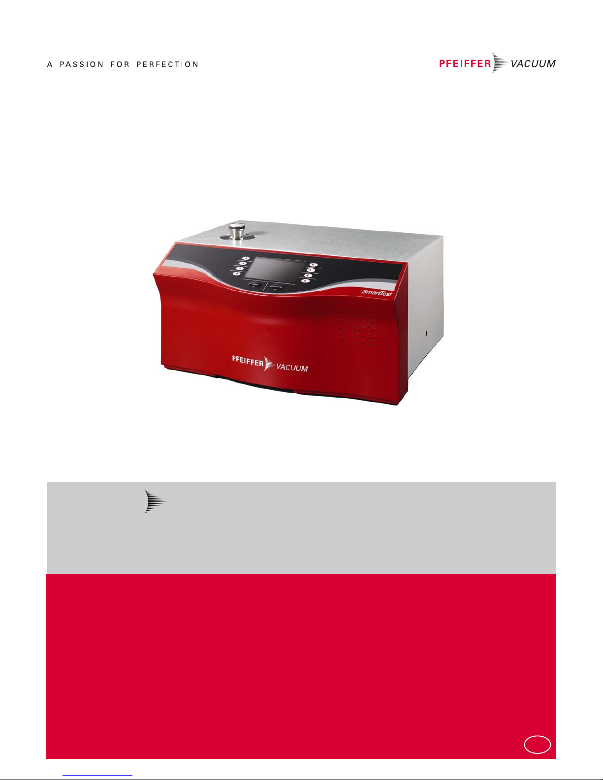
Operating Instructions
SmartTest
HLT 550
HLT 560
HLT 570
EN
2
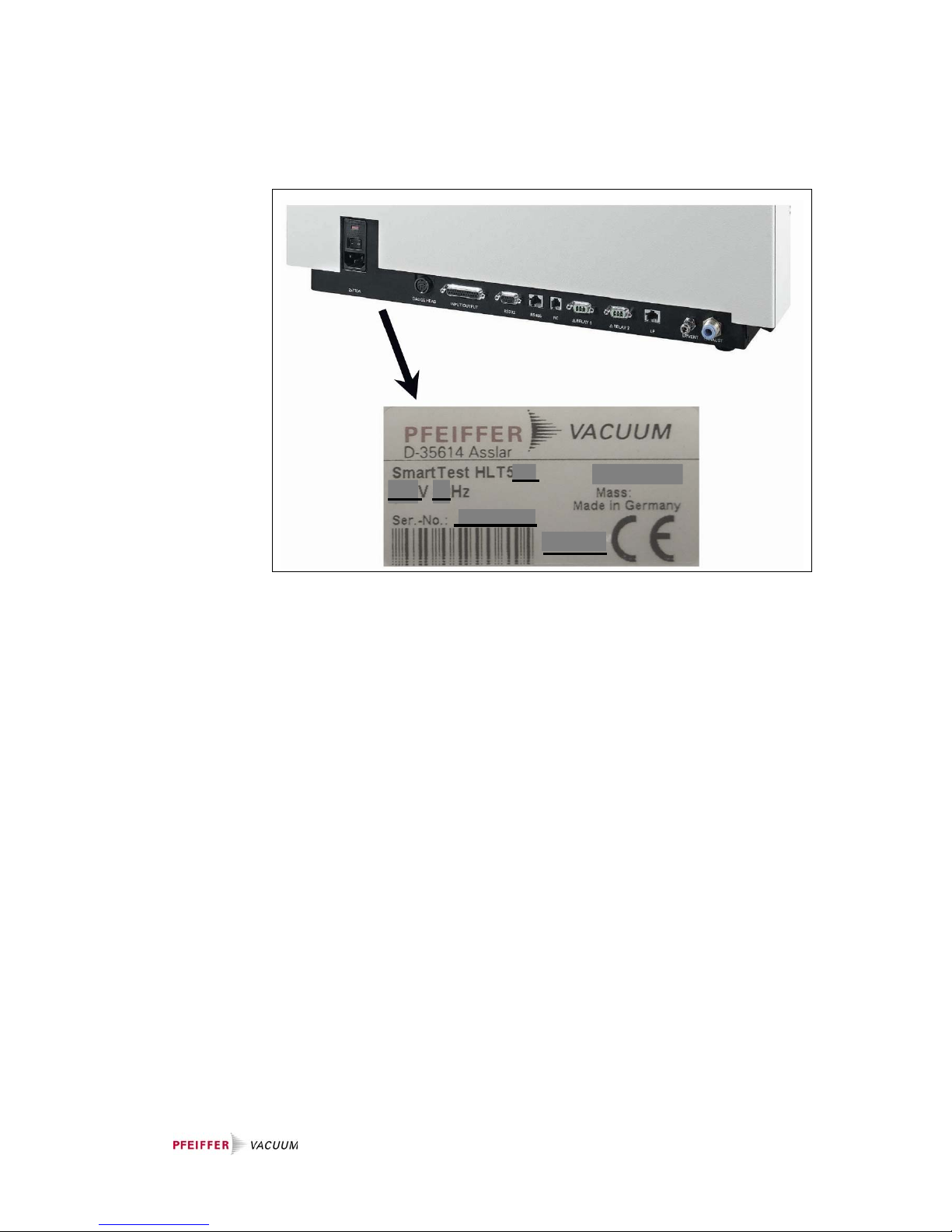
Product identification
The data specified on the rating plate are necessary in correspondence with Pfeiffer
Vacuum. Therefore transfer the data to the copy.
Validity
This document is valid for products with the article number
SmartTest
PT L02 100 (HLT 560, 230 V~, with rotary vane pump UNO 005 A)
PT L02 101 (HLT 560, 120 V~, with rotary vane pump UNO 005 A)
PT L02 102 (HLT 560, 100 V~, with rotary vane pump UNO 005 A)
SmartTest
PT L02 120 (HLT 550, 100 … 230 V~, with backing pump provided by the customer)
SmartTest
PT L02 110 (HLT 570, 230 V~, with diaphragm pump MVP 035)
PT L02 111 (HLT 570, 120 V~, with diaphragm pump MVP 035)
PT L02 112 (HLT 570, 100 V~, with diaphragm pump MVP 035)
This document is based on firmware versions beginning with V2.3.
If the instrument does not work as described, check whether your instrument is
equipped with these firmware versions.
Subject to technical modifications without prior notice. The figures are not to scale.
Fig. 0-1

3
Content
1 Safety 7
1.1 Directions for Use 7
1.1.1 Use of this Manual 7
1.1.2 Symbols Used 7
1.2 General Safety Precautions 8
1.2.1 Use for the Intended Purpose 8
1.2.2 Responsibility and Guarantee 10
1.2.3 Personnel 10
1.2.4 General Safety Rules 11
1.3 Scope of Delivery 14
2 Technical Data 15
2.1 General 15
2.2 Mains Connection 15
2.3 Environmental Data 15
2.4 Measure 16
2.5 Interfaces 17
2.6 Backing Pumps 17
2.7 Turbo Pump 18
3 Description 19
3.1 Measuring System 20
3.2 Detection Principles 21
3.3 Leak Detection Methods 22
3.4 Test Gases 24
3.5 Background Suppression 25
4 Manual Control Elements 29
4.1 Instrument Operation 29
5 Commissioning 30
5.1 Installation, Assembly 30
5.1.1 Unpacking 30
5.1.2 Carrying / Transport 30
5.1.3 Transport Lock 31
5.2 Mount the External Backing Pump 31
5.3 Mounting Accessories 32
5.3.1 Sniffing Probe 32
5.3.2 Remote Control 32
5.3.3 Bypass Option 33
5.3.4 Signal tower 33
5.3.5 Exhaust pipe 33
5.3.6 Venting Line 33
5.4 Mains Connection 33
6 Operation 35
6.1 Switching On and Off 35
6.2 Ready to start 39
6.2.1 Regeneration 40
6.2.2 Check internal test leak 40
6.2.3 Setup 40

4
6.2.4 Calibration 41
6.2.5 Measuring mode Vacuum / Sniffing 41
6.3 Measure 43
6.3.1 Measure with a test item 43
6.3.1.1 Vacuum mode 43
6.3.1.2 Sniffing mode 43
6.3.2 Measured Value Display 44
6.3.3 Display Range Settings 45
6.3.4 Volume 45
6.4 Setup 46
6.4.1 View 46
6.4.1.1 Contrast 47
6.4.1.2 Units 48
6.4.1.3 Time & Date 49
6.4.1.4 Display Range 49
6.4.1.5 Lower Display Limit 50
6.4.1.6 Background at “Ready to Start” 51
6.4.2 Access Control 51
6.4.2.1 Change Menu-PIN 52
6.4.2.2 Change Device PIN 53
6.4.2.3 Calibration Enabled 54
6.4.2.4 Maintenance enabled 55
6.4.3 Language 56
6.4.4 User Settings 56
6.4.4.1 Mode & Mass 57
6.4.4.2 Filter & Zero 59
6.4.4.3 Alarm 61
6.4.4.4 Interfaces 62
6.4.4.4.1 Analog Output 63
6.4.4.4.2 Compact Gauge 65
6.4.4.4.3 Control Location 66
6.4.4.4.4 Relay 67
6.4.4.4.5 Serial Port 68
6.4.4.4.6 Bypass Option 69
6.4.4.5 Parameter save / load 70
6.4.4.5.1 Load PARA Set 1 / 2 70
6.4.4.5.2 Load Factory Settings 71
6.4.4.5.3 Save PARA Set 1 / 2 71
6.4.4.6 Monitoring functions 72
6.4.4.6.1 Flow 72
6.4.4.6.2 Contamination Protection 73
6.4.4.6.3 Volume & Beep 74
6.4.4.6.4 Valves 75
6.4.4.6.5 Evacuation Time & Vent 76
6.4.4.6.6 Calibration Request 78
6.4.5 Calibration Settings 79
6.4.6 Information 80
6.4.6.1 Settings 80
6.4.6.2 System Data 81
6.4.6.3 Vacuum System 81
6.4.6.4 Error List 82
6.4.6.5 Calibration History 82
6.4.6.6 Paging function remote control RC 500 WL 83
6.4.7 Maintenance and Service 84
6.4.7.1 Maintenance device 84
6.4.7.2 Burn In 85
6.4.7.3 Maintenance Interval Components 86

5
6.4.7.4 Maintenance List 86
6.4.7.5 Service 87
6.5 Calibration Vacuum Method 88
6.6 Calibration Sniffing Method 92
6.7 Measuring the Internal Test Leak 95
7 Errors 97
7.1 Malfunction Messages 97
7.2 Warnings 101
7.3 Changing Mains Fuses 105
8 Disposal 107
9 Accessories and Consumer Materials 108
Appendix 110
A Remote Control RC 500 WL 110
B Interfaces 111
C List of Default Values 117
D Pirani-Characteristic 119
E List of literature 120
F Declaration of Contamination 120
G Declaration of Conformity 121

6
7
1 Safety
1.1 Directions for Use
1.1.1 Use of this Manual
This chapter describes the safety requirements which must be observed on all
accounts when using the SmartTest Helium Leak Detector.
All persons working on and with the leak detector must have read and understood
the chapters relevant to their activities. This chapter is binding for all persons and
all activities.
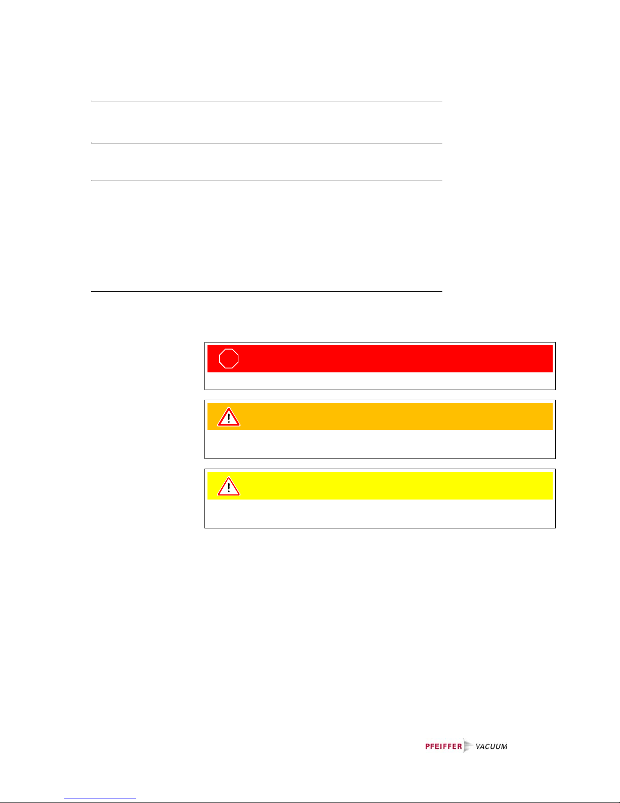
1.1.2 Symbols Used
The following symbols are used with explanatory text to alert people to remaining
risks during use for the intended purpose and to stress important technical
requirements.
STOP
Danger
Specifications for the prevention of bodily injuries of all kinds
Warning
Specifications for the prevention of severe material and environmental
damage
Note
Specifications for handling or use. Failure to observe these can lead to faults
or minor material damage.

8
1.2 General Safety Precautions
1.2.1 Use for the Intended Purpose
The SmartTest Helium Leak Detectors serve for measurement and localization of
small and very small leaks both on components and modules and on fittings and
systems. They are suitable both for underpressure leak testing (vacuum method
with or without partial current operation) and for overpressure leak testing (sniffing
method).
The SmartTest Helium Leak Detectors may only be used for leak testing for the
gases specified in the ”Technical Data”.
The SmartTest Helium Leak Detectors are designed specially for industrial
applications and are used:
• For quality control in manufacturing processes,
• for quality control of production plants,
• as a service unit.
Use for the intended purpose also includes:
• Use of standard and original accessories,
• observance of this document and compliance with the instructions and
regulations therein.
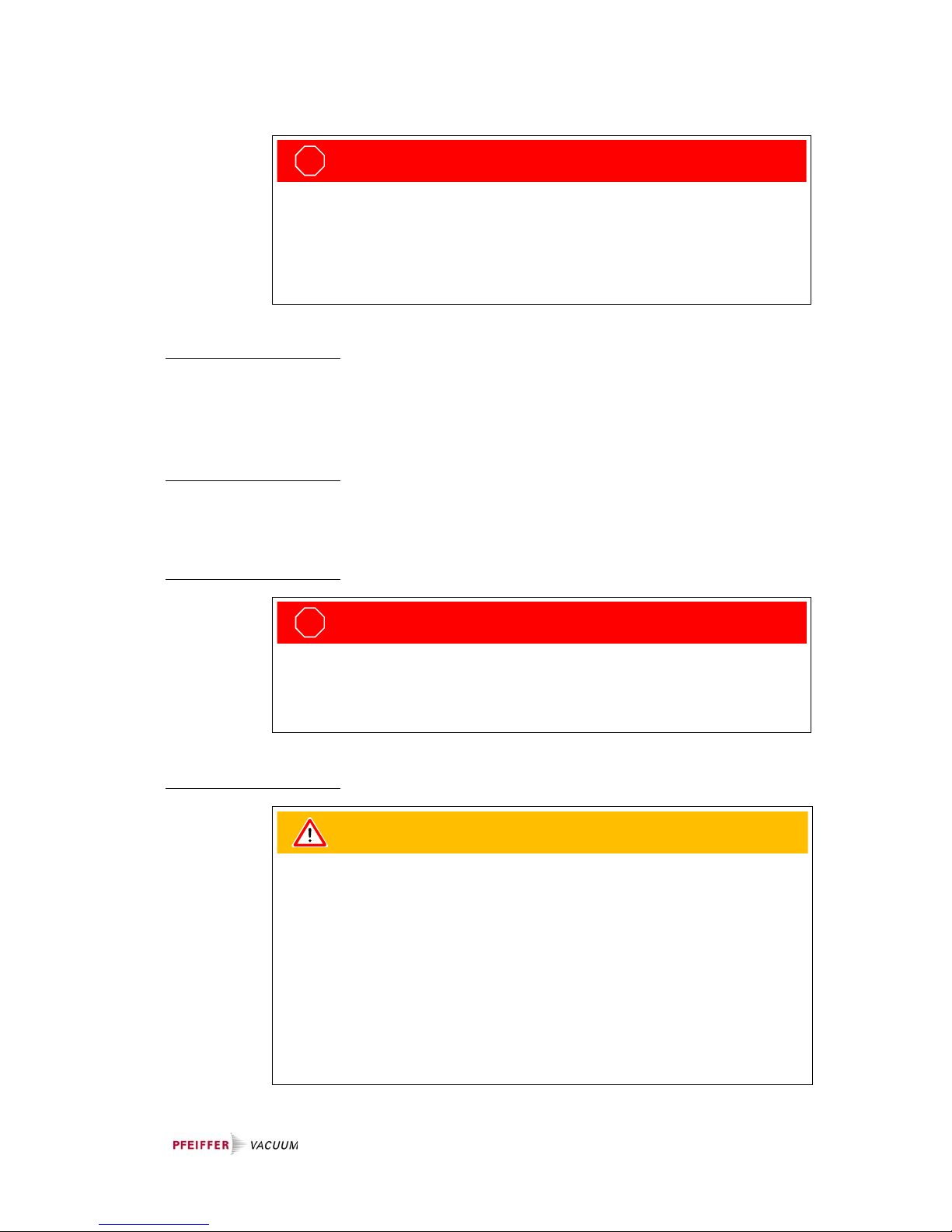
STOP
Danger
Risk of injury due to toxic, flammable and corrosive gases!
Harmful substances, which are pumped down with the SmartTest (Vacuum Mode,
Sniffer Mode), emit through the exhaust and injure people in the surrounding
area. Do not sniff and pump down harmful substances.
STOP
Danger
Risk of injury due to gliding off and falling.
Do not climb on the SmartTest.
STOP
Danger
The SmartTest may tip off its base and injure people.
Place the SmartTest on a stable base.
STOP
Danger
Risk of injury due to sucking connection flange.
If the Vacuum-Mode of the SmartTest is activated, the connection flange may suck
bodily parts around the connection flange.
Keep bodily parts off the connection flange.

9
Warning
The Helium Leak Detector SmartTest may not be operated in standing or under
flowing or dripping water. The same applies for all other kinds of liquids.
Avoid contact of the SmartTest with bases, acids and solvents as well as extreme
climatic conditions.
No corrosive process gases may be pumped with the SmartTest. Failure to
observe this will lead to voiding of the guarantee.
Warning
The leak detector must not directly be switched off after the process, in which
condensable gases or steams are pumped, is finished. It must be running (at least
20 minutes) with opened gas ballast valve until the oil of the pump is freed from
detached steams.
If this instruction is not respected, the pump can be damaged by corrosion effects.
The oil level of the pump has to be controlled regularly.
The normal intervals of changing the oil from the producer have to be taken care
of. See instructions of the rotary vane pump.
Warning
The vacuum pump, vacuum system and sealings may be damaged.
Do not generate overpressure with the SmartTest.
Do only use the SmartTest for leak detection.
Warning
The SmartTest may be damaged by misapplying it as step tread.
Do not use the SmartTest as step tread.
Warning
The SmartTest may be damaged by misapplying it as seat.
Do not use the SmartTest as seat.
Warning
The coating of the filament in the ion source may be damaged.
A burnout of the filament is possible.
Do not pump down those gases with the SmartTest, which contain halogen
molecules (e.g. flour, chlorine).
Such gases are e.g.: SF6

10
1.2.2 Responsibility and Guarantee
Pfeiffer Vacuum will accept no responsibility and provide no guarantee and exclude
itself from all liability in the event that the user or third parties
• use the product for a purpose for which it was not intended,
• fail to observe the ”Technical Data”,
• manipulate the product in any way (conversions, modifications, etc.),
• operate the product with accessories which are not listed in the appropriate
product documentation.
1.2.3 Personnel
Operating personnel
The operating personnel may operate the SmartTest leak detector in normal
operation. The normal operation includes only the following activities:
• Operation,
• the care and maintenance work described in this document.
Note
Caution: Danger of injury
Although this instrument is distinguished by high standards of quality and safety
and has been built and tested according to the latest state of the art, injury or
material damages cannot be totally ruled out in the event of misuse or use for a
purpose which was not intended.
Therefore read this document carefully and especially observe the ”Safety”
chapter. Keep this document close to the instrument at all times.
Note
The SmartTest may be damaged by wrong handling.
Do only run the SmartTest under the allowed conditions of temperature (+10° C to
+35° C) and relative humidity (max. 80% up to +31° C, decreasing to 50% at
+35° C). (See also chapter 2.3)
Note
The SmartTest may be damaged due to lack of inspections.
In order to prevent subsequent damages, check the exterior of the SmartTest
frequently relating to optical damages, and follow the Maintenance Instructions
frequently.

11
Maintenance personnel
The maintenance personnel may operate the SmartTest leak detector in normal
operation and perform maintenance work necessary for trouble-free operation of
the instrument.
In order to be authorised to maintain the SmartTest leak detector, the person
concerned must have taken part in an initial training conducted by a Pfeiffer
Vacuum employee or an experienced member of staff of the system user. (See
Maintenance Instructions IG 0108 BEN for further information.)
Service personnel
The service personnel may operate the SmartTest leak detector in normal
operation and perform maintenance and service work.
The SmartTest leak detector may be serviced only by trained Pfeiffer Vacuum staff
or trained employees of the system user with a similar qualification.
Training as a master electrician or a similar professional training is necessary in
order to work on the electrical components.
See Maintenance Instructions IG 0108 BEN for further information.
1.2.4 General Safety Rules
Legal regulations
The generally applicable legal and otherwise binding regulations for the prevention
of accidents and protection of the environment must be observed in addition to this
document.
Such regulations may also extend to the handling of hazardous substances or
provision/wearing of personal safety equipment etc. for example.
Probable risk
On suspicion that safe operation is no longer possible, the instrument must be
taken out of operation and secured against accidental starting.
This may be the case:
• when the device shows visible signs of damage
• when liquid has penetrated the instrument
• when the instrument is no longer working
• after long periods of storage under adverse conditions
• after great transport stress
Energy connections,
protective earthing
Make sure the instrument is suitable for operating on the local power supply before
connecting it.
The mains plug may only be plugged into a shockproof socket
12
Installation of protective
devices
An exhaust pipe must be installed under certain circumstances.
See Chapter 5.1.2.
Misuse of protective
devices
Only fuses of the specified type with the specified current rating may be used as
replacements.
Opening the instrument
Sending in for repairs
STOP
Danger
Caution: Mains voltage
Improperly earthed products may be dangerous to life in the event of a
malfunction.
Connect the product in accordance with local regulations and earth correctly.
Interruption of the earthed conductor inside or outside the instrument is not
permissible.
STOP
Danger
Caution: Mains voltage, hot parts and rotating components
Removal of the housing shells is dangerous to life and limb.
The housing shells may never be removed in the course of the work described in
this document.
Warning
Products returned to Pfeiffer Vacuum for service or repair must be free of harmful
substances (e.g. radioactive, toxic, caustic or microbiological).
Forwarding contaminated products:
- Adhere to the forwarding regulations of all involved countries and forwarder
companies.
- Enclose a completed Declaration of Contamination.
- Declare all dangers on the package.
Products which are not clearly declared as “free from potentially harmful
substances” will be decontaminated at the expense of the customer.

13
A completed and signed "Contamination Declaration"
(see: www.pfeiffer-vacuum.net and appendix Declaration of Contamination) must
be enclosed with every product sent in for repair.
Spare parts
Only original spare parts may be used for repairs. See maintenance Instructions
IG 0108 BEN.

14
1.3 Scope of Delivery
The scope of delivery includes the following parts:
• Basic device HLT 5xx
• Power-Subcon; relay plug
• Cap for Power-Subcon; relay plug
• Connecting plug: Ventilation sniffer connection
• Filter mat fan 500 μm
• Power cable
• Set of hexagonal wrenches
• Set of fuses
• Documentation

15
2 Technical Data
2.1 General
2.2 Mains Connection
2.3 Environmental Data
Dimensions 550×460×304 mm (L×W×H)
Weight 44 kg HLT 560, HLT 570
34 kg HLT 550
approx. 150 kg HLT 565/572/575 with
carriage and pump
Max. permissible acceleration
in operation
1 G (horizontal)
Test connection DN 25 ISO-KF
Cooling air
Inlet
Outlet
Bottom, with dust filter
Side
Exhaust gas connection For hose ø8/6 mm
External backing pump connection DN 25 ISO-KF
Venting connection (N
2
) Sniffing line connection for hose ø6/
4mm
Maximum pressure at the venting
connection
1.1 bar
Standards and regulations Declaration of Conformity (Appendix)
Degree of protection IP 40
Degree of contamination 2 (EN 61010)
Voltage / frequency 230 V ±10% / 50 Hz
120 V ±10% / 60 Hz
100 V ±10% / 50/60 Hz
Protection class 1
Overvoltage category II
Current <10 A
Power consumption <400 VA (HLT 560)
<150 VA (HLT 550)
<300 VA (HLT 570)
Fuses 2 pieces, 10.0 A slow blow, 250 V,
ø5×20 mm
Temperature

16
2.4 Measure
Vacuum mode
Storage
Operation
–10°C…+55°C
+10 °C … +35 °C
Relative humidity max. 80% up to +31 °C, decreasing to
50% at +35 °C
Use Only indoors,
altitude up to 2000 m above sea level
Noise level <70 dB/A (according to IEC standard)
Operating modi Vacuum / sniffing
Operation standby ≤3 minutes (runup time pump)
Inlet pressure ≤18 mbar (temporarily up to 25 mbar)
Filaments 2 (Iridium yttrated)
Filter stages none,
static
dynamic
Measuring rate
Display rate
20 Hz
3 Hz
Alarm
Acoustics / Volume adjustable
Threshold value / Pre-warning adjustable
Relay output adjustable
On-screen displays Leak rate vs. time, analogue / digital
Smallest detectable leak rate
4
He,
3
He
H
2
according to AVS 2.1
<5×10
-12
mbar l/s
<5×10
-10
mbar l/s
<5×10
-8
mbar l/s
Greatest detectable leak rate
4
He,
H
2
, 3He
1 mbar l/s
1×10
-2
mbar l/s
Measuring range 10
-12
… 1 mbar l/s
Dimensional units of the display mbar l/s, Pa m³/s, sccm, sccs
Torr*l/s, atmcc/s
Detectable gases
4
He, 3He, H
2
Response time (to 63% of the signal) <0.3 s
Suction rate for helium >2.5 l/s at p
inlet
<0.5mbar
Suction rate at inlet with large backing
pump (on HLT 550) depending on the external pump
Pump time for high sensitivity

17
Sniffing mode
2.5 Interfaces
Connecting plug arrangement and detailed data, see Communication Protocol
IG 0105 BEN.
2.6 Backing Pumps
HLT 550
HLT 560
at volume 0.5 l
at volume 10 l
at volume 100 l
2 s (HLT 560, HLT 570)
70 s (HLT 560)
200 s (HLT 570)
700 s (HLT 560)
2100 s (HLT 570)
Pump time up to first measurement
at volume 0.5 l
at volume 10 l
at volume 100 l
2 s (HLT 560, HLT 570)
45 s (HLT 560)
135 s (HLT 570)
500 s (HLT 560)
1300 s (HLT 570)
Internal test leak → Rear of the instrument
Smallest detectable leak rate
4
He, 3He, H
2
Greatest detectable leak rate
4
He,
H
2
, 3He
according to AVS 2.1
<5×10
-8
mbar l/s
1 mbar l/s
1×10
-2
mbar l/s
Measuring range 1×10
-8
… 1 mbar l/s
Dimensional units of the display mbar l/s, Pa m³/s, ppm, sccm, sccs, g/
a, oz/yr, Torr*l/s, atmcc/s
Detectable gases
4
He, 3He, H
2
Response time <1 s with 3 m sniffing line
To be provided by the customer
Pfeiffer Vacuum UNO 005 A Single-stage rotary vane pump, oil
sealed
Volume flow rate 4 m³/h at 50 Hz, 5 m³/h at 60 Hz

18
HLT570
2.7 Turbo Pump
Pfeiffer Vacuum MVP 035 Two-stage diaphragm pump, oil-free
Volume flow rate 2 m³/h
Pfeiffer Vacuum SplitFlow 80 Turbo pump with interstage pumping
Volume flow rate for N
2
60 l/s

19
3Description
The SmartTest Helium Leak Detectors are microprocessor-controller leak detecting
instruments. All the processes in the instrument are controlled automatically.
1 Test connection
KF25 connection for connecting test objects
2 Rear
Rear with mains connection, interfaces, connection for remote control, sniffing
probe and venting
3 Instrument operation
Display and control unit
4 Loudspeaker
Housing opening for loudspeaker signals
5 Fresh air opening
Opening in housing for fresh air supply
6 Exhaust air opening
Opening in housing for exhaust air discharge
Extension stages
Depending on the application the basic SmartTest instrument is extended with:
• an external backing pump
• a carriage
See Operating Instructions Helium Leak detector SmartTest with Cart.
Fig. 3-1

20
3.1 Measuring System
The measuring system consists (simplified) of:
• a test connection
• a backing pump
• a turbo pump
• a few valves
• a helium sensor
The sample is flanged to the test connection. The valves V1, V2, V3 and V4 connect
the sample and the helium sensor without an unsuitable operating state occurring
for this.
A test leak is connected with valve V5 for calibration.
The valve V6 serves for venting so that the sample can be removed again. It is also
used as a sniffing connection.
All valves open electromagnetically and close with spring force.
The measuring tube P1 measures the fore-vacuum pressure, P2 the pressure at the
test connection.
Fig. 3-2
V4
V3
V1
V6
V5
V2
test leak
turbo
pump
part A
helium
sensor
part B
P1
fore-vacuum
pressure
backing pump
external backing pump
(optional)
test
P2
rest connection
Gas connection for
sniffing probe or
venting line

21
3.2 Detection Principles
Counterflow
The sample is connected to the backing pump via valve V2. At a pressure
p2 £ 15 mbar *) the valve V1 to the turbo pump is opened. Helium can get to the
helium sensor through the two partial pumps A and B against the pumping
direction. The mass-dependent compression capacity of the two partial pumps
keeps away heavy gases. The proportion of helium which gets through to the
helium sensor depends on the suction performance of the backing pump and the
compressions of the two partial pumps.
Twi n- Fl ow ™
The gas flow from the sample goes through the test connection.
Twin-Flow™ low: At pressure p2 < 5 mbar
*)
V1 and V3 are open
Twin-Flow™ high: At pressure p2 < 0.5 mbar
*)
V1 and V4 are open
The gas flow passes through partial pump B to the backing pump and the test
connection is pumped up to high vacuum. The suction performance of the partial
pump B is approx. 40 l/s. Only the partial pump A acts in counterflow and allows
light gasses such as hydrogen and helium to get through to the helium sensor on
account of the mass-dependent compression capacity.

22
3.3 Leak Detection Methods
When searching for leaks with the SmartTest the test gas entering or escaping
through leaks in the sample is detected.
For gas to flow through a leak a pressure difference between the inside and outside
of the sample is necessary. For this either excess pressure or vacuum pressure is
generated inside the sample.
Vacuum method
In the vacuum method test gas is blown against the wall of the evacuated sample
from the atmosphere side. It enters the sample at leaks and is fed to the leak
detector.
The sample must be vacuum pressure-proof.
The sensitivity stages
counterflow ⇒ Twin-Flow™ low ⇒ Twin-Flow™ high
are run through.
The detection limit is lower than in the sniffing method. The helium concentration
at the leak must be known in order to quantify the leak. The state of equilibrium
must be waited for.
* Factory settings. Other valve settings. See Chapter 6.4.4.6.4.

23
Sniffing method
In the sniffing method the test gas escaping from leaks in the sample into the
atmosphere is detected.
The sample must withstand the applied test pressure.
In operation with the sniffing probe a constant gas flow is sucked in from the
atmosphere. The helium proportion of the air (5.2 ppm) causes a leak rate display
of approx. 1×10
-6
mbar l/s which can be eliminated by the ZERO function.
To detect a leak, the sniffing probe is applied to the points of the sample under
helium overpressure which are suspected of leaking. An increased leak rate value
indicates an increased concentration of helium and therefore a leak. The higher the
pressure and the helium concentration in the sample, the smaller the leaks which
can be detected.
The sensitivity stages
counterflow ⇒ Twin-Flow™ low
are run through.
The detection sensitivity and the quantifiability of the leak rate are less favourable
than in the vacuum pressure leak detection.

24
3.4 Test Gases
For reasons of economy and detection sensitivity 4He (helium with mass 4) is
generally used as a test gas for leak detection. Under certain conditions, e.g. at
increased
4
He concentration on the sample, it may be useful to change to a different
test gas such as
3
He (helium with mass 3) or H2 (hydrogen, mass 2). These gases
can also be detected with the leak detector.
STOP
Danger
Caution: Danger of explosion
Hydrogen forms a highly explosive gas mixture with air.
Great caution is necessary when using hydrogen! No smoking, no naked flames,
avoid sparks.
Note
Because of the high percentage of water in typical residual gases, the leak rate
background in the measurement of hydrogen is fairly high (in a range from
10
-7
mbar l/s).
For the leak detection the test gas can be diluted with a neutral gas such as
nitrogen or argon. This helps to reduce contamination of the atmosphere and an
increase in the signal background especially in case of serious leaks. The leak rate
signal is then of course reduced according to the test gas concentration.

25
3.5 Background Suppression
The background signal may increase dependent on the measuring conditions
(e.g. high percentage of helium in the ambient air).
The background signal can be suppressed to enable easy measurement of small
leak rates despite a high background.
The background suppression can be locked or activated automatically with every
START. See Chapter 6.4.4.2.
Rising background
By pressing the ”ZERO” key the momentary raw signal (e.g. at time t1) is saved as
a background value and is then subtracted from the following measured values.
See Chapter 6.4.4.2.
The status message Zero appears in the measured value display.
Fig. 3-3 Rising background
Item Description
1 raw signal
2 displayed leak rate

26
Falling background
If the raw signal falls below the saved background value this is automatically set
equal to the raw signal (e.g. at time t1). As soon as the raw signal rises again (e.g.
at time t2), the saved background value remains constant. Signal increases are
displayed clearly as a leak.
This greatly simplifies measurement of the smallest leak rates.
Absolute measurement
If you want to see the raw signal (including background), press the ZERO key for
about 3 s.
The saved value is set to zero (e.g. at time t3), the background signal is no longer
suppressed.
Fig. 3-4 Falling background
Item Description
1 raw signal
2 saved value
3 displayed leak rate
Item Description
1 displayed leak rate
2 raw signal

27
Zero constant function
By pressing the ”ZERO” key the momentary raw signal (e.g. at time t1, t2, t5) is
saved as a background value and is then subtracted from the following measured
values/raw signals.
The status message Zero appears in the measured value display.
Fig. 3-5 Absolute measurement
Fig. 3-6 Zero constant function
Item Description
1 raw signal
2 saved value
3 displayed leak rate

28
The automatic background suppression is locked. The zero value is retained after
pressing the Stop key. Pressing the Zero key again overwrites the zero value. The
zero value is set to ”0” at Power Off or changing the zero function.
If the raw signal of the leak rate drops below the saved value/background value (see
time: t3 to t4), it is not evaluated but the slightest detectable leak rate/detection limit
is displayed.
So leaks are not displayed (raw signal) that are smaller than the saved underground
value (saved value).

29
4 Manual Control Elements
4.1 Instrument Operation
The operating unit is the display, operation and control unit for the leak detector.
1 START/STOP key
The measuring process is started and stopped with the START/STOP key.
2 ZERO key
ZERO activates the background suppression in measurement mode. When you
press the key longer than 3 seconds you will deactivate the underground
pressure.
3 Softkeys
The function of these keys depends on the current operating state. The
respective meaning appears in the display.
4 Display
The display shows measured values, operating modi, instrument parameters
and their values as well as the meaning of the softkeys.
Fig. 4-1 Functions of the buttons on the display

30
5 Commissioning
5.1 Installation, Assembly
Despite good attenuation and vibration decoupling of the mechanical pumps in the
SmartTest, vibrations of the instruments can never be ruled out totally.
To avoid humming (vibration of the instrument on a base with a similar resonance
frequency) a firm, stable base should be chosen which only exhibits a slight
tendency to vibrate.
5.1.1 Unpacking
The leak detector is delivered in a special packing ready for operation.
5.1.2 Carrying / Transport
Note
See the Chapter ”Technical Data” (Chapter 2) regarding the permissible
ambient temperature, degree of protection, voltages, max. acceleration of the
instrument in operation etc.
Note
The packing must be checked for damage before unpacking. If damage to the
packing or the instrument itself is visible, please file a damage report with the
shipping agent responsible immediately.
We recommend you to keep the special packing. This original packing offers the
best protection for transport over a great distance or for returning the leak
detector for servicing.
Note
Only applies for type HLT560.
The pump (with oil filling) may be tilted by a maximum of 90°. In operation by a
maximum 10°.
STOP
Danger
Caution: Heavy product
When carrying heavy items your back can be injured or other injuries can
occur when the item slips out of your hands.
Two people should carry the product.
 Loading...