

Page 1
PREH
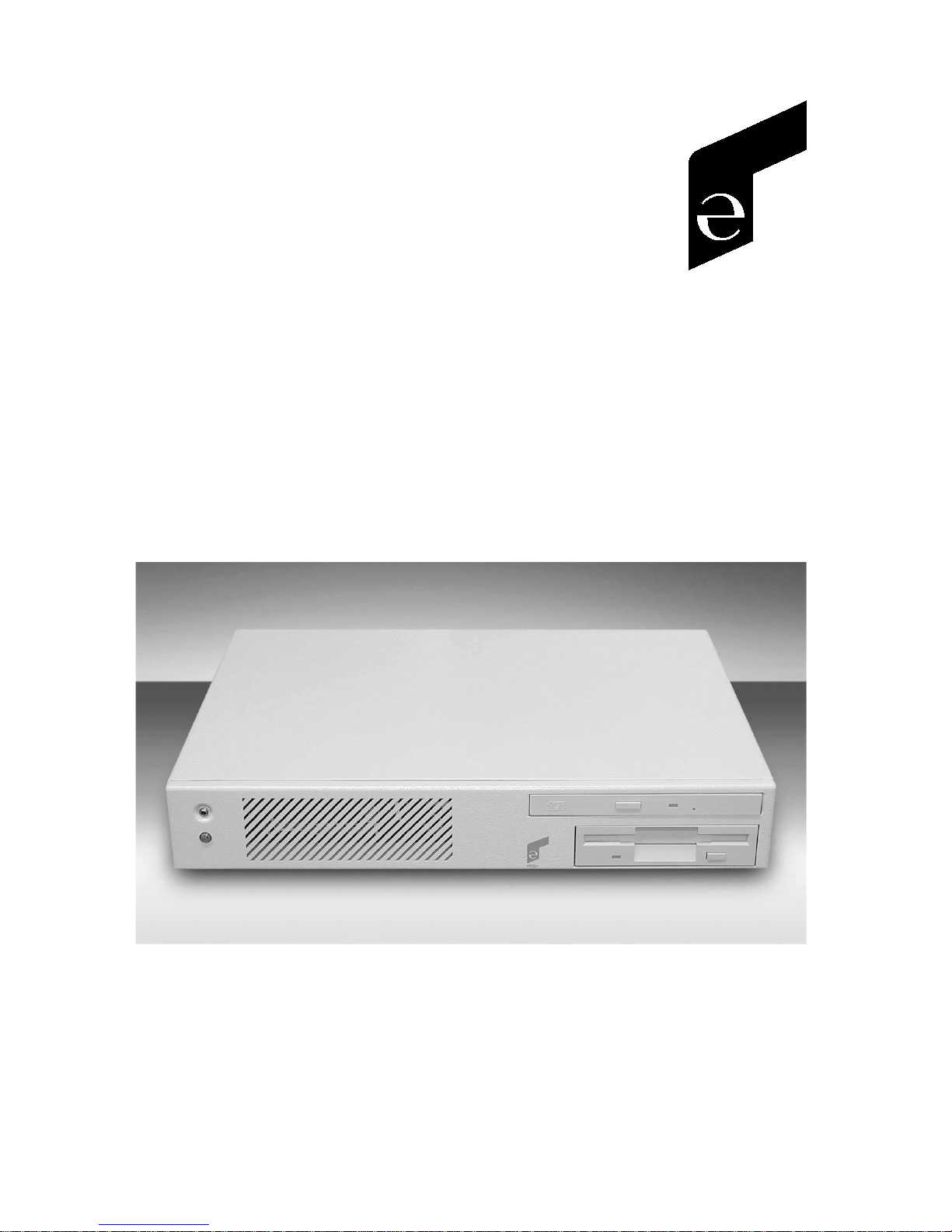
Preh Flat POS 2000
User Manual and Technical Data
Page 2

Table of Contents
1 General 3
1.1 Overview 3
1.2 Working environment 3
1.3 Contents of packaging 4
2 System Characteristics 5
2.1 System board 5
2.2 Hard disk 6
2.3 Diskette drive 6
2.4 CD-ROM / DVD drive (Option) 6
3 Controls and Connections 7
4 Opening the Housing 8
5 System Board 10
6 Installation 10
6.1 General 10
6.2 Cable installation 11
6.3 Switching on for the first time 12
6.4 Set-up Program 13
6.5 Booting the system 13
6.6 Installation of operating systems 13
6.7 Driver installation 14
7 Technical Data 14
7.1 Electronics 14
7.2 ESD and EMC 15
7.3 Climatic parameters 15
7.4 Mechanical 15
7.5 Materials and surfaces 15
8 Care and Maintenance 16
9 Troubleshooting 16
9.1 General 16
9.2 Fault finding 16
9.3 Additional help 17
10 Additional Notices 17
11 Warranty 17
12 Declaration of Conformity 18
13 FCC Warning Statement 18
ENGLISH
2
Page 3

1 General
1.1 Overview
We congratulate you on the purchase of our Preh Flat POS 2000 compact PCs.
The Flat POS 2000 is a compact cash desk computer for individual, custom
solutions at the Point-of-Sale. Its compact design and small dimensions make
the Flat POS 2000 ideal for use in the retail, restaurant, gastronomy and
hotel branches.
This compact PC has a standard motherboard (100 MHz FSB) with Ethernet
controller and sound-chip on board, 512 kB 2nd level cache, 3,5“ floppy
drive, at least 6,0 GB hard disk and a great number of POS-specific interfaces.
As standard, the Flat POS 2000 is delivered with an AMD® processor of at
least 500 MHz and at least 32 MB working memory.
Options for the Flat POS 2000 are, Disk-on-ChipTM (DOC) and 768 MB SDRAM
(3x168 PIN SDRAM) (PC-100 conform). Further options include an integrated
CD-ROM or DVD drive. The PC is notable, above all, for its compact dimensions of approx. 340mm x 260mm x 60mm. On the front side of this PC are a
recessed reset switch and a power LED. An external power supply is required.
1.2 Working environment
Thanks to its compact dimensions and low weight, the Flat POS 2000 can be
used anywhere. However, the Preh Flat POS 2000 should be treated with the
same care as any other quality electronic hardware.
Please, therefore, note the following conditions for the working environment:
• Do not operate the Flat POS 2000 in places where it may be subjected to
excessive humidity and/or dust.
• Do not subject the Flat POS 2000 to excessive heat or direct sunlight.
• Avoid heavy vibration or shocks.
• Do not operate the Flat POS 2000 in aggressive environments
(acid vapours...).
ENGLISH
3
Page 4

• Ensure that the ventilation slots on the front and the fan grids at the rear
do not become obstructed.
• Do not subject the Flat POS 2000 to any strong magnetic fields.
Important notices:
• For the operation of the Flat POS 2000, use only the original power
supply included. If another power supply is used, we do not accept any
responsibility and guarantees or warranties do not apply.
• Remember that the built-in hard disk is very sensitive to blows, shocks
and vibration. Therefore, your Flat POS 2000 should be handled with the
necessary care. We cannot guarantee the hard disk against or accept any
responsibility for damage that can be shown to result from inappropriate
handling.
• Correct operation with peripherals can only be guaranteed if these carry
the CE or FCC marking.
1.3 Contents of packaging
Please check, before attempting to operate your Flat POS 2000, that all the
following are present and visibly free from damage:
1. Preh Flat POS 2000,
2. Driver CD with peripheral drivers and Preh Programmer,
3. Supply cable,
4. Jumpers,
5. Ferrite clamp,
6. Power supply,
7. Descriptions: User manual and technical data
manual for system board (IPC POS-566/566L)
ENGLISH
4
Page 5
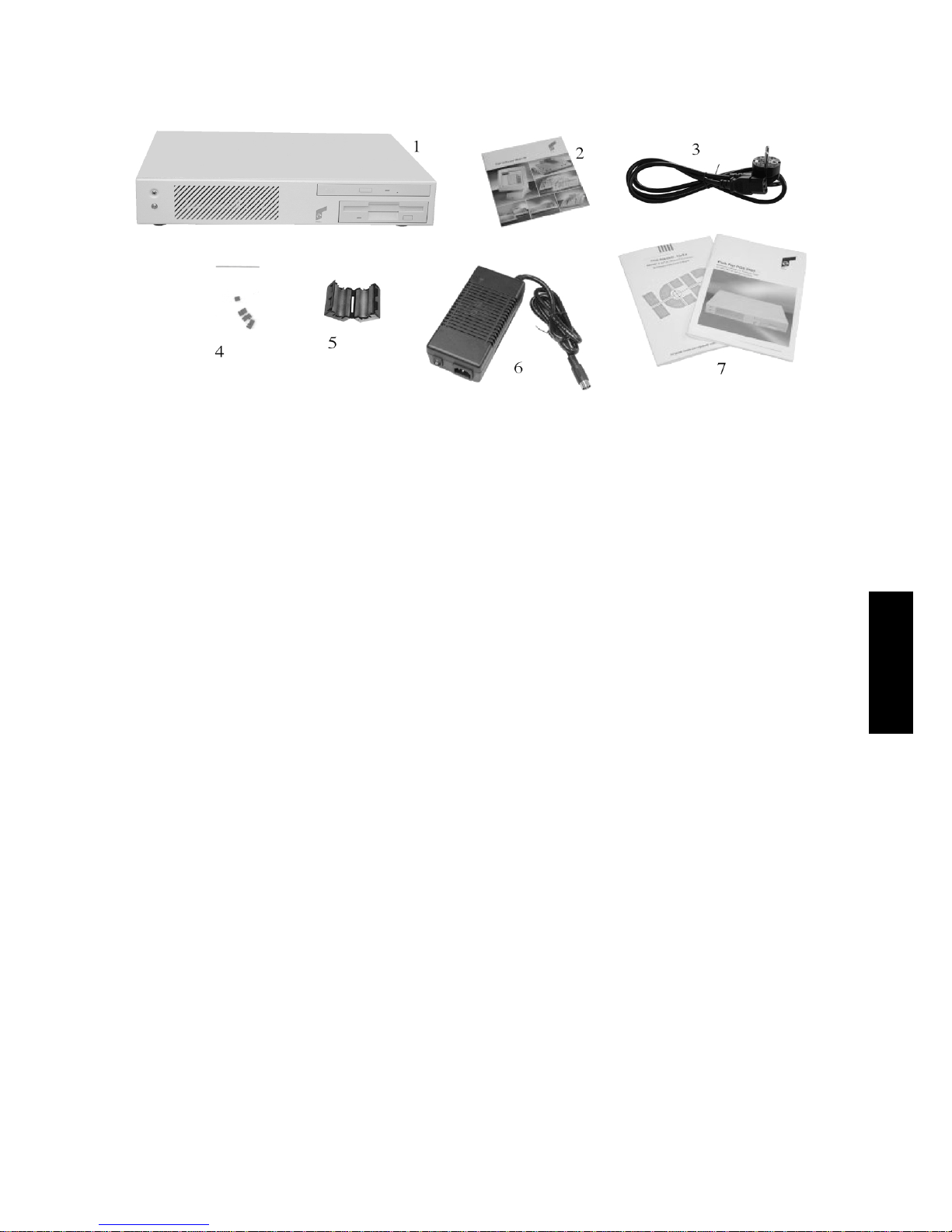
fig. 1: Contents of packaging
2 System Characteristics
The Preh Flat POS 2000 is a compact computer system, based on a system
board with a 100 MHz front side bus (FSB) for AMD® K6®, Pentium® or
Pentium® compatible processor.
2.1 System board
The integrated system board is suitable for the following processors:
• AMD® K6® / K6®-2 / K6®-3 up to 500 MHz,
• Pentium® MMX up to 233 MHz,
• IDT C6,
• Cyrix 6x86MX and compatibles.
The processor is seated on a 321-pin ZIF-socket. The standard version of the
Preh Flat POS 2000 is fitted with a processor, type AMD® K6
On request, the Preh Flat POS 2000 can be fitted with another type of
processor.
®
-2 (≥ 500 MHz).
ENGLISH
The chip-set is an Ali 5 with 100 MHz FSB. The system board is factory-fitted
with 512 KB second level cache memory.
The Board supports, amongst others, the following interfaces:
• two SPP/EPP/ECP parallel interfaces (of which one is brought out),
• four serial interfaces (three RS-232C, one RS 232-C or RS-422/485),
• two USB interfaces (Universal Serial Bus),
5
Page 6

• one SVGA interface,
• one PS/2 mouse interface,
• one PS/2 keyboard interface,
• one RJ 45 10/100 Mbps Ethernet Realtek RTL 8139 IEEE 802 interface,
• one each of Line in, Line out, Mic. sound connections,
• one 12 V output for Preh Touch or Screen Commander,
• and one RJ 11 connection for cash desk drawer.
As working memory, all 168 Pin SDRAM modules can be used that comply
with the PC-100 specification. Three memory bank slots (168 Pin) are available, each of which can be fitted with up to 256MB of RAM. The PC is
delivered with at least one 32MB module fitted.
2.2 Hard disk
Since both the technology and capacity of hard disks are subject to continuous change, no precise data for the capacity of the factory fitted disk can be
given here (presently at least 6,0 GB).
However, any normal 2.5" IDE hard disk can used. The BIOS can automatically recognise the hard disk. Further details of the hard disk registration in
BIOS can be found in the accompanying motherboard description.
2.3 Diskette drive
The Flat POS 2000 is factory-fitted with a 3.5“ diskette drive. Any normal
3.5“ HD diskettes can be used.
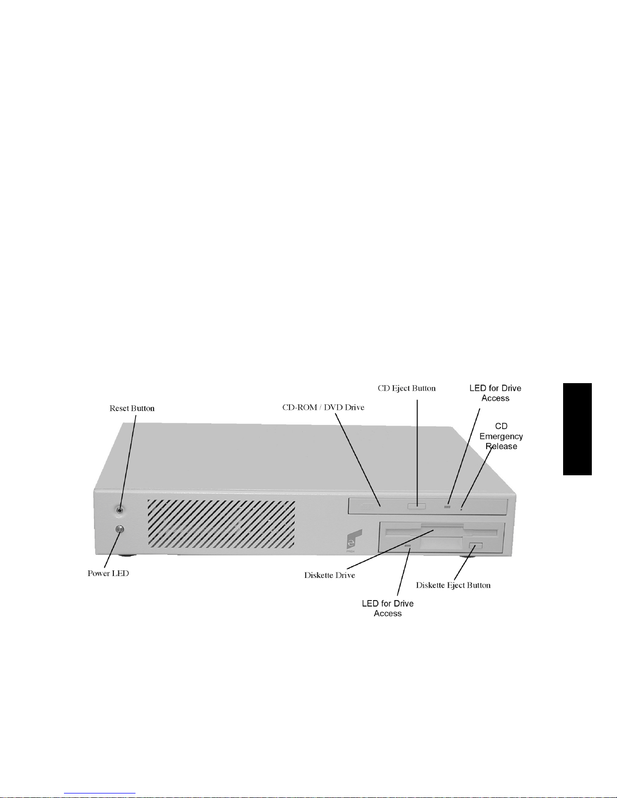
To remove diskettes from the drive, press the eject button (fig. 2).
2.4 CD-ROM / DVD drive (Option)
The Flat POS 2000 can optionally be factory-fitted with an integrated slimline CD-ROM or DVD drive. Here, too, continuous change means that no
precise details can be given, in this case of speed (presently at least 24x
speed CD).
ENGLISH
To open the CD-ROM or DVD drive, press the CD eject button (fig. 2). The
drive will open and can carefully pull the CD tray out to the stop.
6
Page 7
Now place the CD or DVD, label side up, in the drive. Take care that the disk
clicks onto the spindle by exerting light and even pressure near the centre.
The CD-ROM tray can be closed by gentle hand-pressure until it clicks home.
If you have problems with the CD-ROM drive and it cannot be opened, you
can use light pressure with a pointed object (e.g. paper clip) to operate the
emergency release (fig. 2).
3 Controls and Connections
Before working with the Flat POS 2000, you should make yourself familiar
with its controls and connections.
The following pictures show the controls and connections of the Preh Flat
POS 2000:
fig. 2: Controls (front view)
ENGLISH
7
Page 8
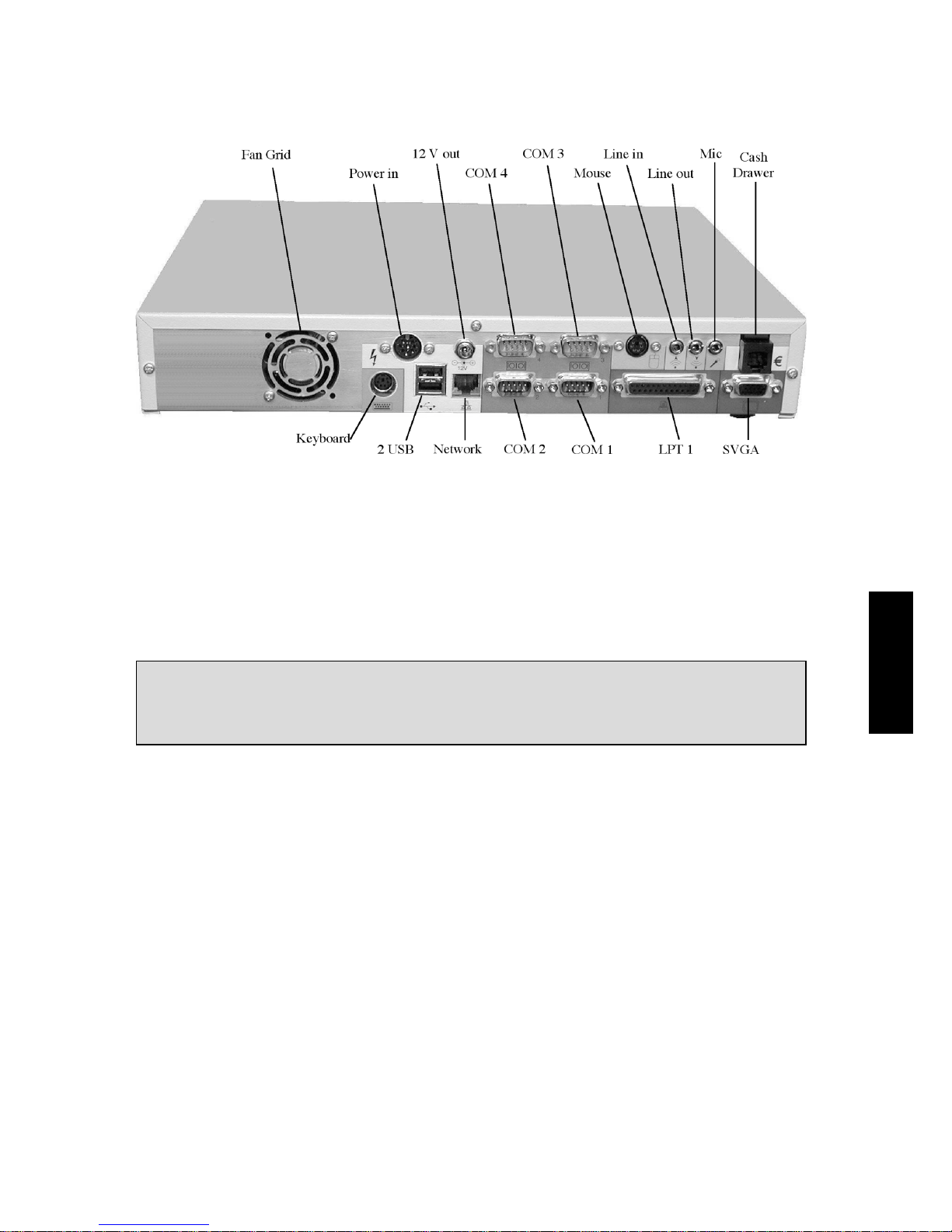
fig. 3: Connections (rear view)
4 Opening the Housing
In order to change any settings or make any extensions to the system board,
you can open the housing of the Flat POS 2000.
Attention: Only open the housing after the mains plug has been
withdrawn. When working on the system board, observe the
proper precautions against electrostatic discharge!
First lay the Flat POS 2000 with the upper side of the case on a soft surface.
Use a torx-head screwdriver to loosen the four fixing screws on the underside
of the case (see fig. 4).
ENGLISH
8
Page 9
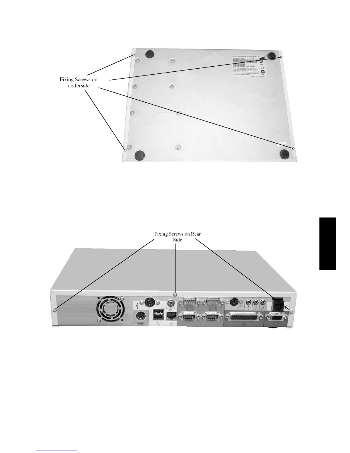
fig. 4: Fixing Screws on Underside
Place the Flat POS 2000 back on its feet. Use a torx-head screwdriver to
loosen the three fixing screws on the rear side of the case (see fig. 5).
ENGLISH
fig. 5:Fixing Screws on Rear Side
9
Page 10
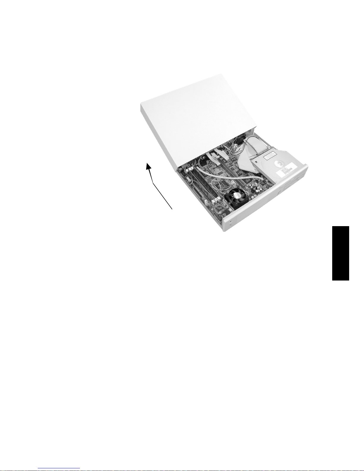
Now you can slide the cover carefully to the back, tilt it upwards and remove
(see fig. 6). The system board is now open for access.
fig. 6: Opening the Housing
5 System Board
The positions of the most important hardware components, pin allocations,
and possible hardware settings via the appropriate jumpers, are to be found
in the accompanying system board handbook, ICP POS-566/566L.
6 Installation
6.1 General
To operate the Flat POS 2000 you will need, in addition to the delivery
package, a VGA or SVGA monitor and a keyboard with PS/2 connection.
A pointer device (e.g. mouse) is recommended but not essential. PS/2 or
serial pointers are suitable.
The positions of the connectors are to be found in fig. 3.
ENGLISH
10
Page 11
6.2 Cable installation
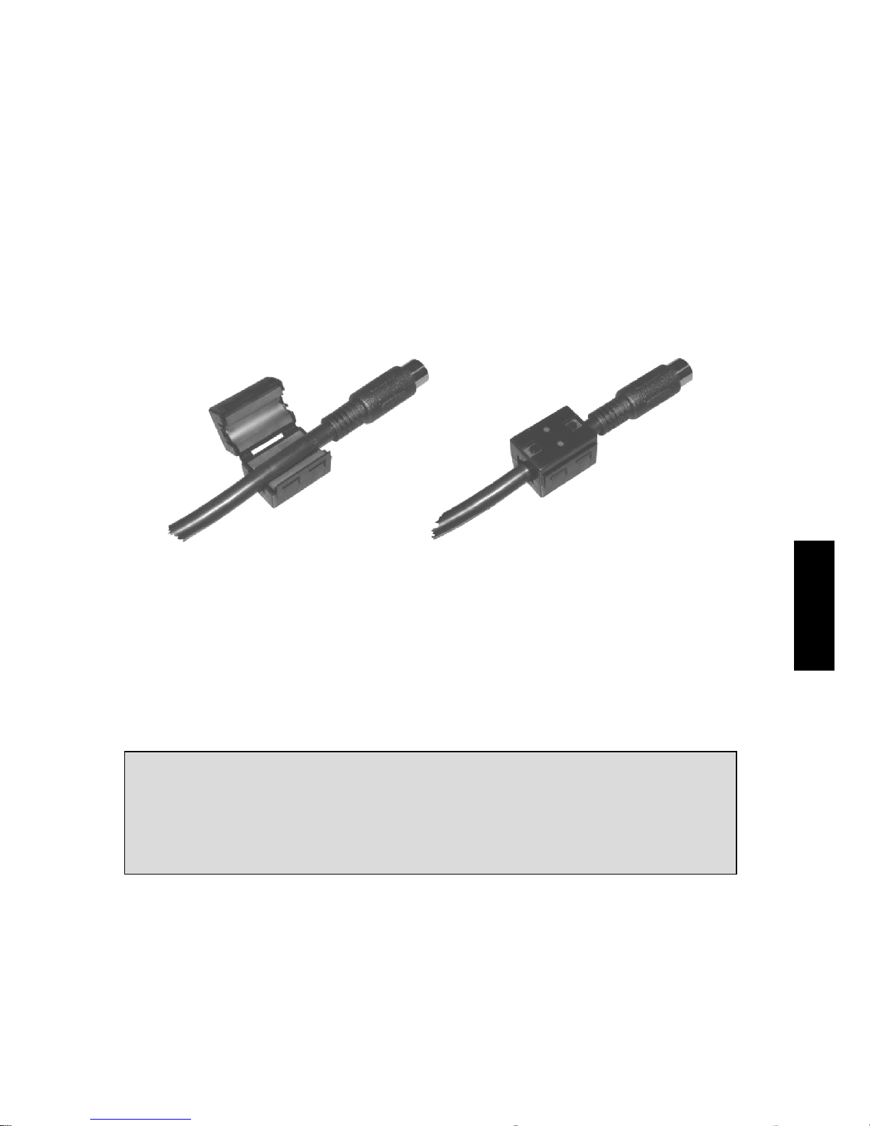
Before starting with the cable installation, you must first fit the ferrite clamp
to the power supply cable directly behind the 8-pin DIN plug.
To do this, proceed as follows:
• Lay the power supply cable directly behind the 8-pin DIN plug in the
open ferrite clamp,
• Close the clamp and press it together until there is an audible click.
fig. 7: Fitting the Ferrite Clamp
First connect the monitor to the connector marked “SVGA” (see fig. 3) on the
Flat POS 2000. Connect your pointer device, if available, and all other peripherals that you wish to use, to the appropriate interfaces.
NOTICE:
Do not connect a telephone cable to the cash drawer interface (see fig. 3)
Before connecting the power supply cable supplied to the power supply,
you must ensure that the on/off switch on the power supply unit is OFF.
Always switch the Flat POS 2000 on and off using the on/off switch on the
power supply unit (never break or make the mains connection with the
power supply switched on).
Plug the power supply unit supplied into the Power in socket. Now you can
connect the Mains cable to the power supply and plug it into a socket with
earth pin.
ENGLISH
11
Page 12
Important Notice!
Many malfunctions can be traced to loose or incorrectly connected cables.
You should, therefore, check that all cables are connected to the correct
interface. Always make use of the locking clamps on the various connections (VGA, LPT 1, COM 1 - COM 4), since the connectors may otherwise
become loose during use.
6.3 Switching on for the first time
Always switch on the monitor first. To start the Flat POS 2000, you must
switch on using the on/off switch on the power supply unit. As the system
starts, the power LED (see fig. 3) will light.
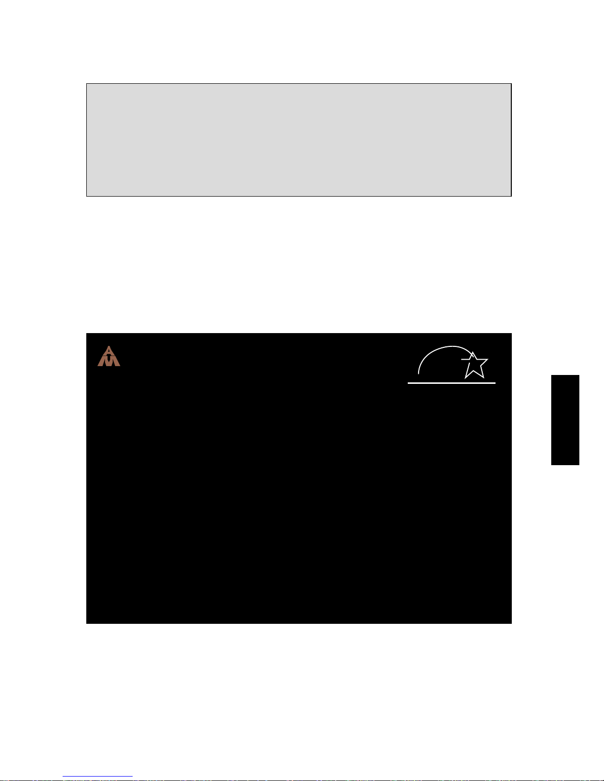
The following picture will now appear on the monitor:
American
Megatrends
AMIBIOS (C ) 1996 American Megatrends Inc.,
energy
POS-566 V 2.0 PXE
EP A POLLUTION PREVENTER
Main Processor : AMD-K6 (tm) –2/450P
Processor Clock : 450MHz
Checking NVRAM . .
65536KB OK
Hit DEL if you want to run SETUP
(C) American Megatrends Inc.,
51-1229-000000-00111111-071595-41E_43C-168-0
fig. 8: System Start
If you now press the DEL button on the keyboard, you will start the SETUP
program.
ENGLISH
12
Page 13

6.4 Set-up program
The Flat POS 2000 has an AMI PCI/ISA BIOS (Basic Input Output System)
installed. This includes the basic input and output functions, the internal
Power On Self-Test (POST) and the set-up service program. With the set-up
service program, you can set up and optimise the basic characteristics of the
system and rectify incorrect configurations. The system settings are stored in
the SRAM of the clock module, which has a battery back up. They are thus
retained when the system is switched off.
Remember that you should only change the system settings when you make
hardware changes, your system does not operate reliably or the system
performance is not optimised.
In chapter 4 of the accompanying manual, ICP POS-566/566L, the various
sub-menus and their settings are described.
6.5 Booting the system
After successful completion of the POST (internal self-test) the system looks
in the bootable media for the operating system to be loaded. You can set the
boot sequence in the CMOS set-up.
Further information on setting the boot sequence is to be found in the
accompanying manual, ICP POS-566/566L.
6.6 Installation of operating systems
To install an operating system on the internal hard disk drive, you require a
bootable start medium.
This will usually be a bootable floppy disc (e.g. Windows start diskette) or a
bootable CD-ROM (e.g. Windows NT, Windows 2000, Linux). In this connection, you should pay particular attention to the correct setting of the boot
sequence in the CMOS set-up (see manual, ICP POS-566/566L).
The procedures to be followed will be found in the corresponding operating
system manuals.
ENGLISH
13
Page 14

6.7 Driver installation
To use all the features of the Preh Flat POS 2000 you will need to install
driver software. On the accompanying Preh Utility and Driver CD are drivers
for the integrated devices such as sound chip, Ethernet adapter, graphic chip
and E2Key for many operating systems.
You will find further information in the file FLATPOS.TXT in the directory
\POS_PC\FLAT-POS on the Preh Utility and Driver CD.
7 Technical Data
7.1 Electronics
A) Power consumption
Supply voltages and ratings: +5V / 10A
+12V / 2A
-12V / 500mA
B) Hard disk
Supply voltage: +5 VDC
Standby: typical 0,1 W
Read/Write: typical 2,2 W
Start: typical 2,7 W
C) Diskette drive
Supply voltage: +5 VDC
Standby: typical 3 mA
Read/Write: typical 250 mA
D) CD-ROM drive
Supply voltage: +5 VDC
Standby: typical 20 mA
Read: typical 600 mA
ENGLISH
14
Page 15

7.2 ESD and EMC
CE marking (see also chapter 11)
Radiated interference:
• EN55022, class B
• FCC part 15, class A limits
Interference immunity:
• No interference from electromagnetic fields, test field strength 3V/m; no
interference from electrostatic discharge in accordance with EN61000-4-2
• Interference immunity limit, 8 kV
7.3 Climatic parameters
Temperature ranges Relative humidity
Storage/Transport: -10°C to +60°C 20% to 80%
Operation: +5°C to +40°C
Air pressure Climatic test class
700 hPa to 1060 hPa 21 days 40°C 80%RH
7.4 Mechanical
Housing
Colour: grey-white, similar to RAL 9002
black, similar to RAL 9005
Dimensions: approx. 340mm x 260mm x 60mm (W x D x H)
7.5 Materials and surfaces
• Housing electrolytically galvanised sheet steel (enamelled)
• Feet polyurethane
ENGLISH
15
Page 16
8 Care and Maintenance
The Flat POS 2000 can be cleaned with a soft cloth. Where necessary, the
cloth can be slightly moistened and a mild cleaner can be used. Always
switch off your Flat POS 2000 before cleaning. When cleaning, take care that
no liquids penetrate to the inside of the housing.
9 Troubleshooting
9.1 General
Attention: The Flat POS 2000 contains no electronic components that can
be repaired or maintained by the user. You should, therefore, not attempt
to carry out any repair work yourself. Doing so will cause you to loose any
warranty rights for this product.
To return the product, the original packaging should be used and care taken
to pack it correctly. If this is not the case, transport damage can occur for
which the person returning the product is solely responsible.
9.2 Fault finding
Many faults can be traced to loosened or wrongly connected cables, wrong
configurations or incorrect installation of the operating system. First make
sure that all the cable connections have been correctly made and/or check
once again any system and configuration settings you may have made. In
this connection you should read the appropriate sections of the operating
system handbook or the accompanying handbook, ICP POS-566/566L.
If your system will not start any more, first check the settings in the CMOS
set-up (see handbook, ICP POS-566/566L).
16
ENGLISH
Page 17

9.3 Additional help
If you have problem using the Flat POS 2000, you should contact your
system or software partner.
Our service for data input systems can be reached at:
e-mail: [email protected]
Fax: +49 9771 92-105
10 Additional Notices
All Preh products are subject to a continuous improvement process. We
therefore reserve the right to make technical changes.
We give notice that inappropriate handling, storage, intervention and or
modification can lead to faults and damage in use.
Insofar as you, as the user, alter our products, we can neither make any
guarantee nor accept any responsibility for the altered product, except in the
case that we have given express written agreement for your application.
This applies, in particular, for unprofessional repair and maintenance work.
Any rights to damages against Preh-Werke – on whatever legal grounds – are
excluded, except in case of intent or gross negligence. The above limitation
does not apply to rights to damages arising out of the law on product
liability.
This user manual applies exclusively to the supplied product, Preh Flat POS
2000.
11 Warranty
Preh guarantees that products leave its works free from manufacturing and
material defects. The warranty period is one year and starts from the date of
delivery.
Otherwise Preh’s general conditions of sale apply.
ENGLISH
17
Page 18

12 Declaration of Conformity
We hereby certify that declarations of conformity are available for all variants
of the Preh Flat POS 2000.
You can, of course, request these from us, giving the exact type designation
(see the type plate on the underside of the unit).
Preh-Werke GmbH & Co.KG
An der Stadthalle
D-97616 Bad Neustadt an der Saale
Fax: (09771) 92-105
13. FCC Warning Statement
NOTE: This equipment has been tested and found to comply with the limits
for a Class A digital device, pursuant to Part 15 of the FCC Rules. These limits
are designed to provide reasonable protection against harmful interference
when the equipment is operated in a commercial environment. This equipment generates, uses and can radiate radio frequency energy, and, if not
installed and used in accordance with the instruction manual, may cause
harmful interference to radio communications. Operation of this equipment in
a residential area is likely to cause harmful interference in which case the
user will be required to correct the interference at his own expense.
ENGLISH
18
Page 19

Copyright
© Copyright Preh-Werke GmbH & Co. KG 2000
Published by Preh-Werke.
Preh-Werke reserve the right to update or change, without prior notice, the products described in
this handbook as well as the handbook itself.
This handbook may not be reproduced, processed or translated into electronic form or other
languages without the prior written permission of Preh-Werke.
Trademarks
Brands and product names mentioned in this handbook are trademarks or registered trademarks
of the current owner.
e.g:
POS 566/566L trademark of ICP Electronics
AMI trademark of American Megatrends, Inc.
Intel trademark of Intel Corporation
AMD trademark of Advanced Micro Devices, Inc.
Cyrix trademark of VIA Technologies Corporation, Inc.
Microsoft trademark of Microsoft Corporation
19
ENGLISH
Page 20

Preh-Werke
PREH
GmbH & Co KG
An der Stadthalle
D-97616 Bad Neustadt an
der Saale
Germany
Phone (09771) 92-0
Fax: (09771) 92-105
http://www.preh.com
Preh Electronics, Inc.
590 Telser Road, Unit B
Lake Zurich, IL 60047
USA
Phone 847.438.4000
Fax 847.438.5522
http://www.preh.com
Preh (Singapore) Pte. Ltd.
3 Toh Tuck Link
#
04-01 German Districentre
Singapore 596228
Telefon 875 11 10
Fax 875 11 01
http://www.preh.com
ENGLISH
03555-104/000
10.00
20
 Loading...