

Page 1

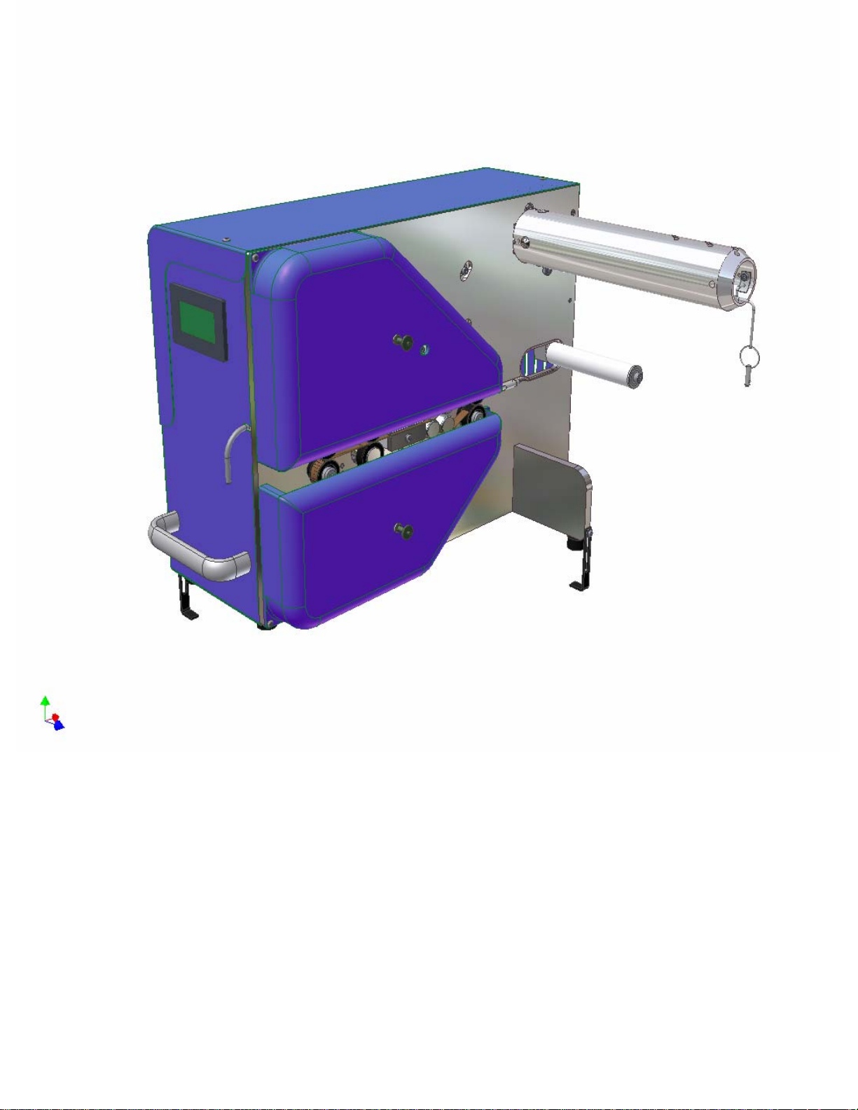
SAFETY, OPERATION, AND MAINTENANCE
Pregis AIRSPEED 5000
AIR CUSHION MACHINE
Version 3
Page 2
Page 3

OPERATING SAFETY
PREGIS AIRSPEED 5000
AIR CUSHION MACHINE
Operator safety and the safety of others in the work
area depends on the operator using common sense,
good judgment and reasonable care while operating
the machine. The Safety, Operation and
Maintenance manual, and warning labels affixed to
the machine, provide notification of specific potential hazards.
NOTE: Refer to the Safety Alerts instruction for
additional safety-related information.
Safety
The following instructions are only a guideline and
should be considered a supplement to your plant's
comprehensive safety program. Your business' policy supersedes these guidelines if at any time the
two contradict each other.
1. Read and understand the manual. If after read-
ing the manual you have questions, get
answers before working with the machine.
2. Read and understand all of the danger, warning
and caution statements in the manual and on
the signs attached to the equipment.
3. Never deface or remove factory installed
warning decals. If a decal ever becomes lost,
damaged or illegible, report this condition to a
supervisor and obtain a replacement decal.
4. Keep the work area clean and uncluttered.
Walking surfaces should always be free of
packing material and debris to prevent a slipping or tripping hazard.
5. Ensure that all covers, guards and other safety
devices are in place. Never defeat a safety
device for any reason.
6. Follow the manufacturer's recommended startup
procedure.
7. Never leave the equipment unattended while
operating. Shut the machine off if you must
leave the work area.
8. Keep body parts and clothing away from mov-
ing components such as nip rolls, power transmission components, sealing belts, etc. Never
reach into the machine for any reason while it
is in motion.
9. Understand what will happen when you oper-
ate the various controls.
10. Understand the proper web path and the safe
method for threading the web.
11. Learn the safe procedure for clearing the
machine of web wraps or jams.
12. Exercise extreme care whenever it is required
to inspect or adjust the machine while it is in
motion. NEVER reach into the machine for
any reason while it is motion.
13. Understand which adjustments are operator
adjustments; contact a maintenance person to
make all other adjustments.
14. Never operate or work around equipment if
you are under the influence of alcohol, drugs
or medications that can make you less alert or
affect your judgment.
Page 4
SAFETY ALERTS
PREGIS AIRSPEED 5000
AIR CUSHION MACHINE
Operator safety and the safety of others in the work
area depends on the operator using common sense,
good judgment and reasonable care while operating the machine. The Safety, Operation and
Maintenance manual, and warning labels affixed to
the machine, provide notification of specific potential hazards.
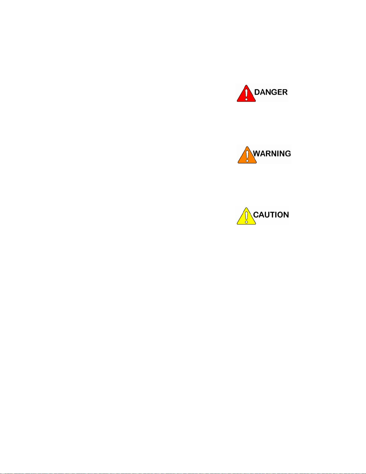
Safety signs are used to alert operating and maintenance personnel to potential hazards. The machine
manual also calls attention to potential hazards
with statements describing the hazard. Both the
safety signs on the machine and the warnings in the
manual use signal words to identify the seriousness
of the potential hazard. These signal words are
Danger, Warning and Caution.
A definitely hazardous situation that, if
not avoided, will result in serious injury or
death.
A potentially hazardous situation that, if
not avoided, could result in serious injury
or death.
The meanings of the signal words and the level of
potential hazards they represent must be clearly
understood before attempting to operate or maintain the machine. If, at any time, a safety sign on
the machine becomes lost, damaged or illegible,
contact Pregis to order replacement signs at no
charge.
A potentially hazardous situation that, if
not avoided, may result in minor injury (or
machine damage).
Page 5
INTRODUCTION
PREGIS AIRSPEED 5000
AIR CUSHION MACHINE
Introduction
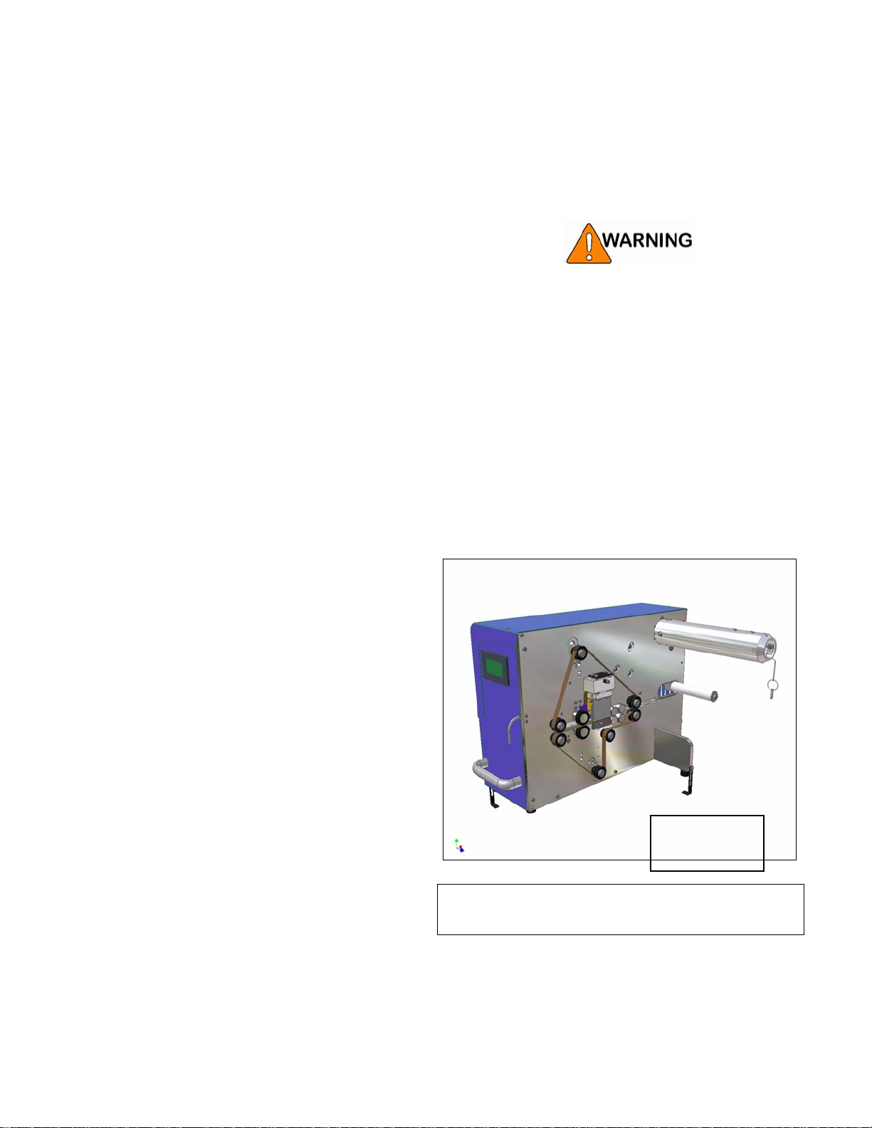
The Pregis AIRSPEED 5000 (Figure 1) produces
air-filled packing cushions in any quantity, as needed. The ability to create packing cushions on
demand saves storage space and reduces packaging
material waste.
Packing cushions are created in strings of individual cushions. The string can be torn apart at perforations cut between each cushion. The perforation
repeats can be 6" or 8" on film webs 8.88" or
10.88". Cushions are created at a constant rate of
up to 75 feet per minute (fpm) of film feed. The
amount of cushions created per minute will vary
with the film cushion size.
Operation
Electrical shock or unexpected machine
movement can cause injury. DO NOT
operate machine with guards removed or
covers open.
For your safety, follow your company’s
lockout/tagout policy as required for each
task.
The film web is a continuous tube in which there are
pairs of cross seals, with a perforation placed bet wee n
them, spaced every four to eight inches. The cross
seals stop 0.56"-0.62" from one edge of the film. This
creates a gap or tube, in the film direction, along that
edge of the film.
DO NOT Operate
With Guards
Removed!
.
Fig 1
Pregis Air Speed 5000
Page 6
The film is loaded onto the unwind shaft with the
n
p
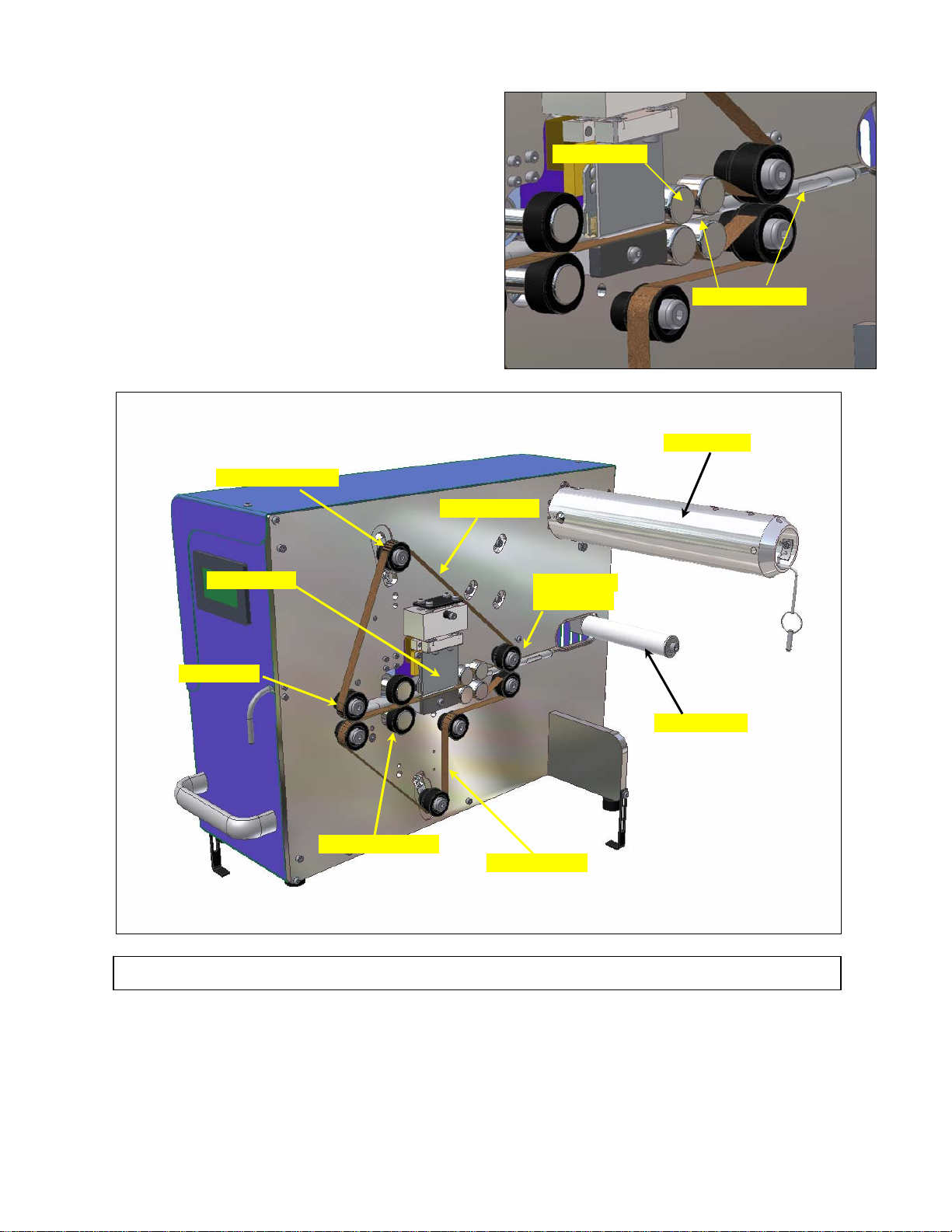
seal gap edge facing the inside. The film is then
routed around the outside of a spring-loaded roller.
This roller maintains film tension by controlling
the amount of braking applied to the unwind shaft.
The seal gap edge of the film is then guided over
the end of the air injection tube. The air injectio
tube extends through the seal section, and past the
outfeed nip rollers. See Figures 2.
Belt Tension Roller
Upper Seal Belt
Diverter rollers
Air Injection Slots
Unwind Shaft
Sealing Guard
Guide Roller
Outfeed Nip Roller
Figure 2
Front/Side View - DO NOT O
See Fig. 3 for
Interior view
Tension Roller
Lower Seal Belt
erate With Guards Removed!
Page 7
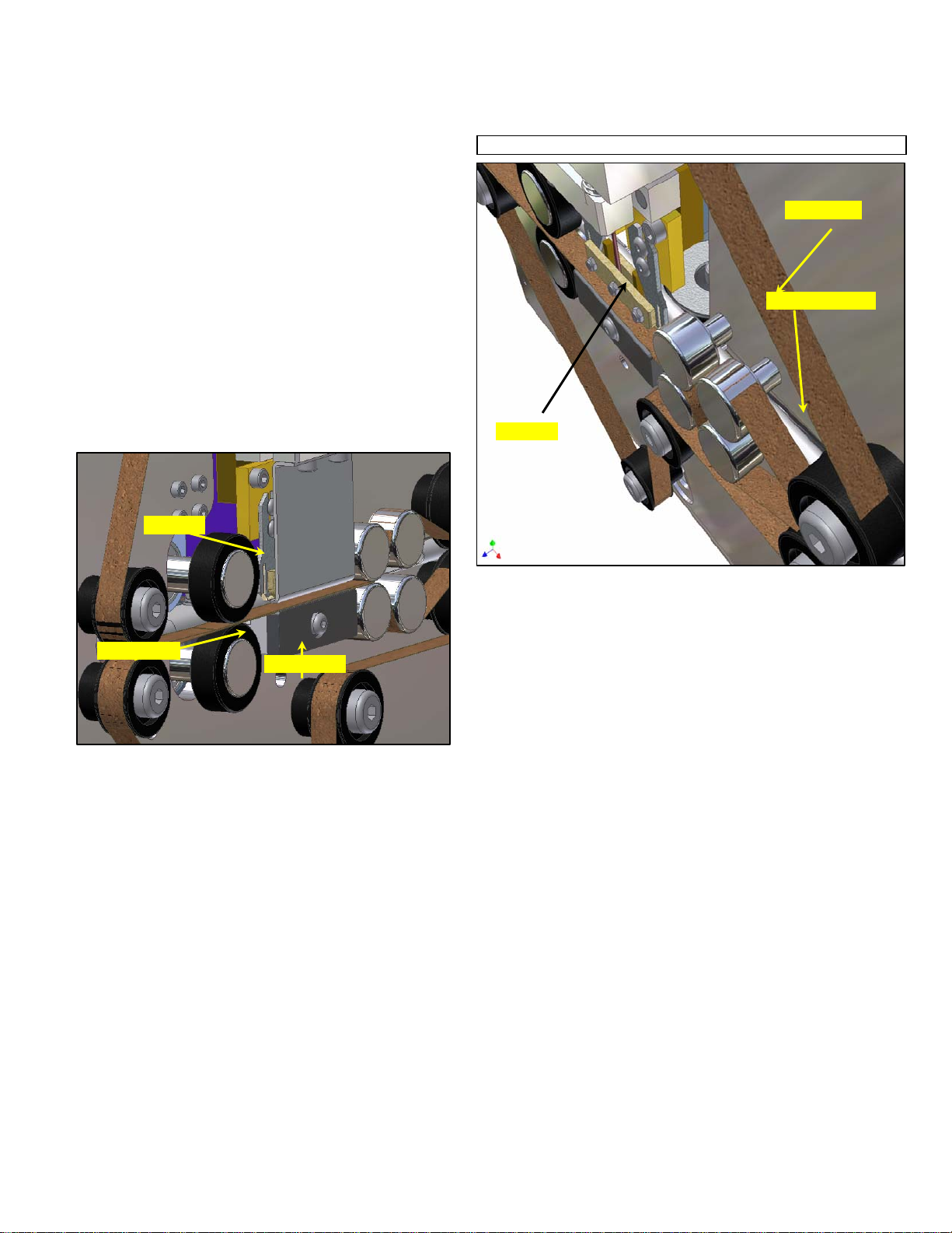
An upper and lower Teflon sealing belt are each
y
routed around a set of guide rollers, a spring-loaded
tensioning roller, and nip rubber rollers. Film is
pulled from the roll by the infeed and outfe ed nips.
See Figure 2.
The film is captured between the upper and lower
sealing belts as it travels through the sealing section. The sealing head assembly is spring-loaded.
The sealing wire presses down against the inside of
the upper sealing belt. This downward pressure
forces the sealing belts, with the web sandwiched
between, against the lower platen.
The inflated web of inflated cusions is pulled
through the seal section by the outfeed nip roller.
See Fig 2
Upper Seal Guard/Clamp removed for clarit
Sealing Belt
Air injection tube
Seal Wire
Seal Wire
Lower Platen
Lower Block
Page 8
OPERATOR CONTROLS PREGIS AIRSPEED 5000 AIR CUSHION MACHINE
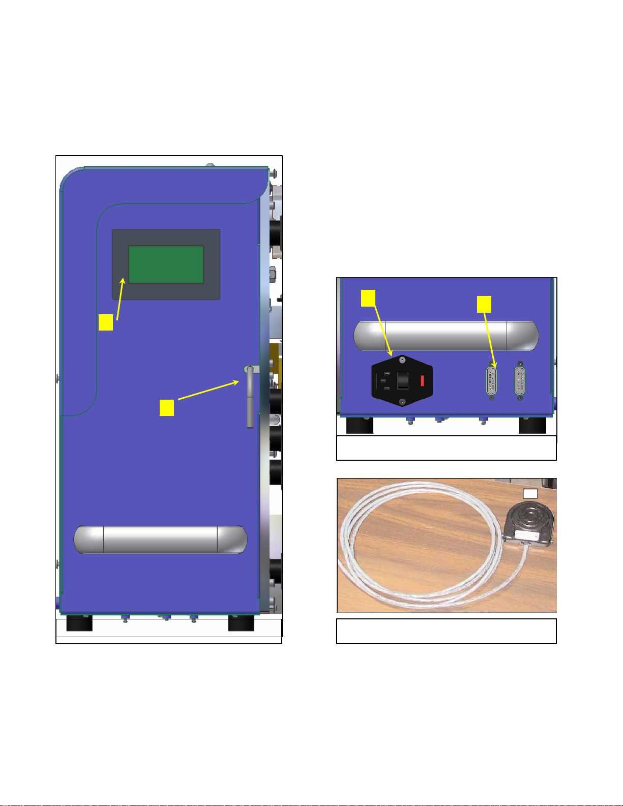
Controls
#1
1. Operator Interface Screen
Used to monitor, select and adjust the air
cushion machine operating parameters.
2. Nip Open/Close Lever
Used to raise and lower nip drive rollers.
3. Power Switch
Used to turn electrical power on and off.
4. Input interface ports
Used to connect secondary equipment.
#3
#4
#2
Fig. 1
Operator Control Panel
Fig. 2
Infeed End View
Fig. 3
Optional Footswitch
Page 9
Operator Interface Touch screen
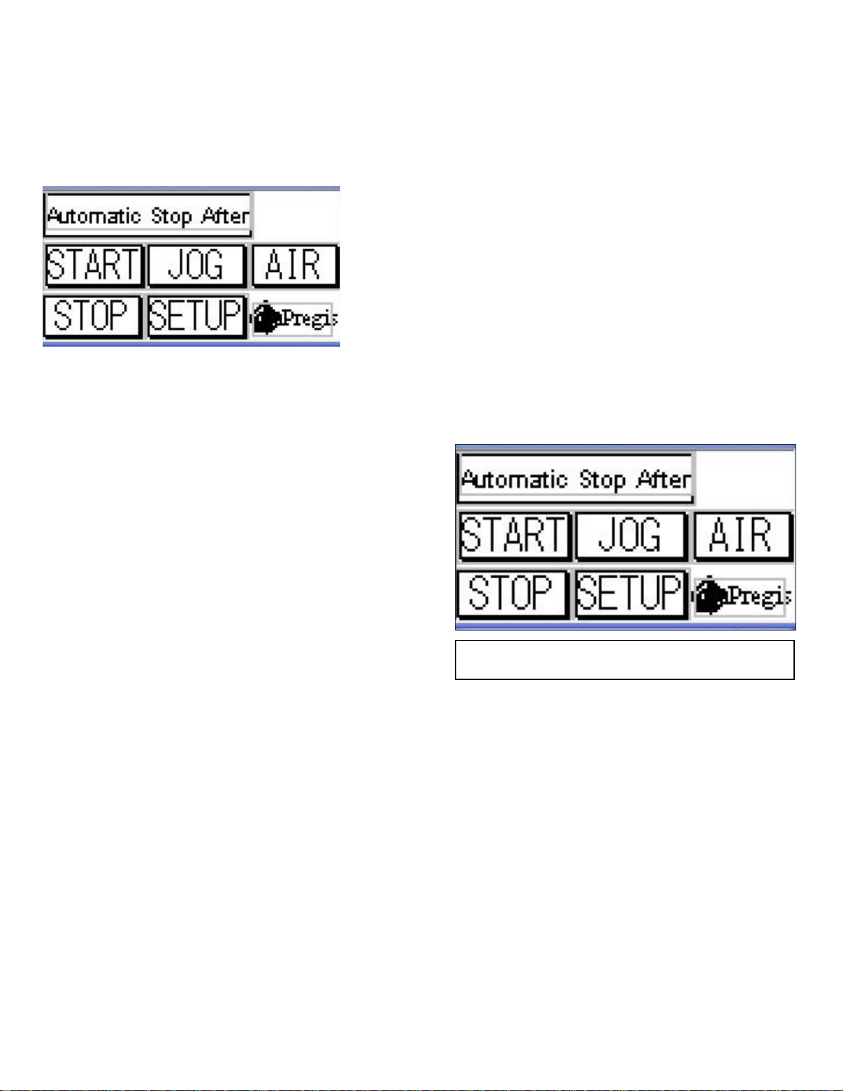
Main (Ready to Run)
This screen allows the operator to select the
machine operating mode. See Figure 5.
The three (3) operating modes include:
Normal Operation
The machine is started and runs continuously
until manually stopped, or film supply is
depleted. Machine operation is controlled by
the control panel START and STOP buttons,
See Figure 5.
Fig. 5
Main Screen - Normal Operation
Page 10
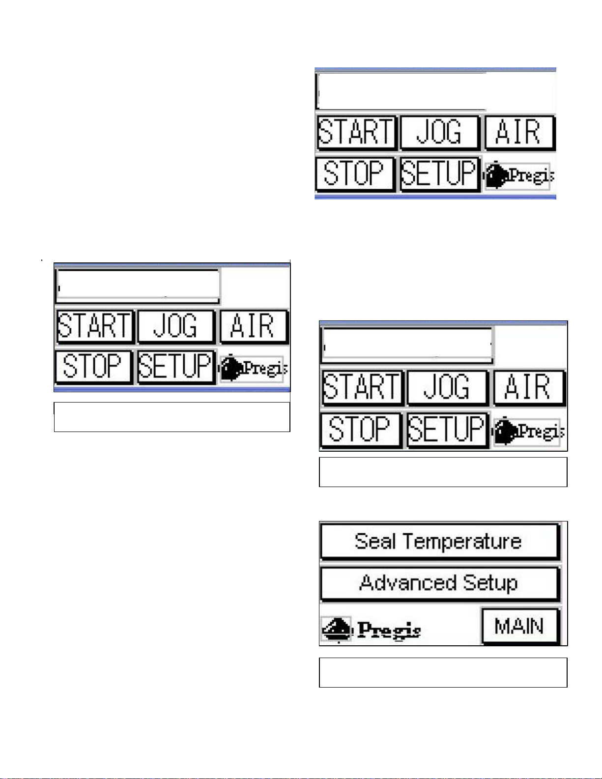
Automatic Stop after xx ft.
A
Used to manually select a length of film to run.
The machine will stop once the proximity sensor detects the set film length has been run.
The quantity of cushions created for the selected film length will vary with the cushion size.
See Figure 6.
Touch the screen in the area of the “**FT.”
The screen will change to the keyboard. Use the
keyboard to select the footage required then
touch the enter key (bent arrow). See Fig. 9
PAUSED
uto Stop After 15 FT.
The Basket with xx ft.
Used to select a length of film to automatically
run once the collection basket/bin is low. A
sensor mounted above the bin detects when the
bin is low, after which the selected length of
film is then run. See Figure 8.
Main Screen –Auto stop
Fig. 6
Touch the screen in the area of the “**FT.” The
screen will change to the keyboard. Use the
keyboard to select the footage required then touch
the enter key (bent arrow). See Fig. 9
Fill Basket With
Fig. 7
Main screen - Fill the Basket
15 FT.
After the sensor initially detects the bin as low,
there is a four second delay before the cushion
machine is started. This prevents the cushion
machine from pulsing on and off.
Once the preset length of film has been run,
the Main screen “RUNNING” message
changes to “PAUSED”, and the machine stops.
Fig. 8
Setup Screen
Page 11
Setup the Machine
Selecting this function brings up the Advanced
Setup and Seal Temperature (Figure 8),
Seal Temperature
Selecting this function routes you directly to the
Seal Temperature screen. See Figure 10.
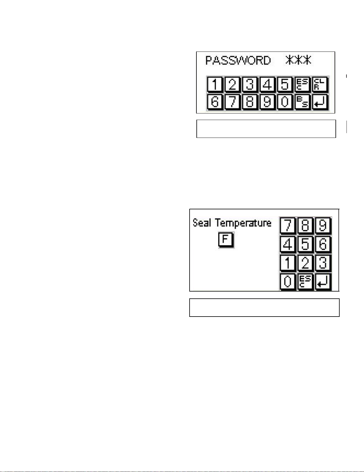
NOTE: Management may protect the seal tem-
perature setting by requiring a password
to be entered before allowing access to
the Seal Temperature screen. If so, the
Password screen (Figure 9) will appear.
ADVANCED SETUP Screens
All MACHINE SETUP screens list the current setting, or selection for the specific parameter, as the
Actual value. If applicable, the unit of measure for
the values is listed at Units.
Fig 9
Password Screen
Seal Temperature
Used to set the sealing (wire) temperature. (Fig.10)
once a value has been entered and accepted, the
setup screen appears. Touch the “Main” button to
return to the main screen.
435
Fig.10
Seal Temperature
Page 12
OPERATING PROCEDURE
PREGIS AIRSPEED 5000
AIR CUSHION MACHINE
Start-Up
Electric shock hazard. DO NOT open
cover. Do not touch moving components.
Failure to heed may result in injury.
4. If not already closed, turn nip Open/Close lever
to close the tape drive nips.
NOTE: Jogging the film will not initiate infla-
tion.
1. Slide the roll of film, with the unsealed air
tube slot to the inside, over the shaft. The
inside of the core is gripped by the shaft
plungers.
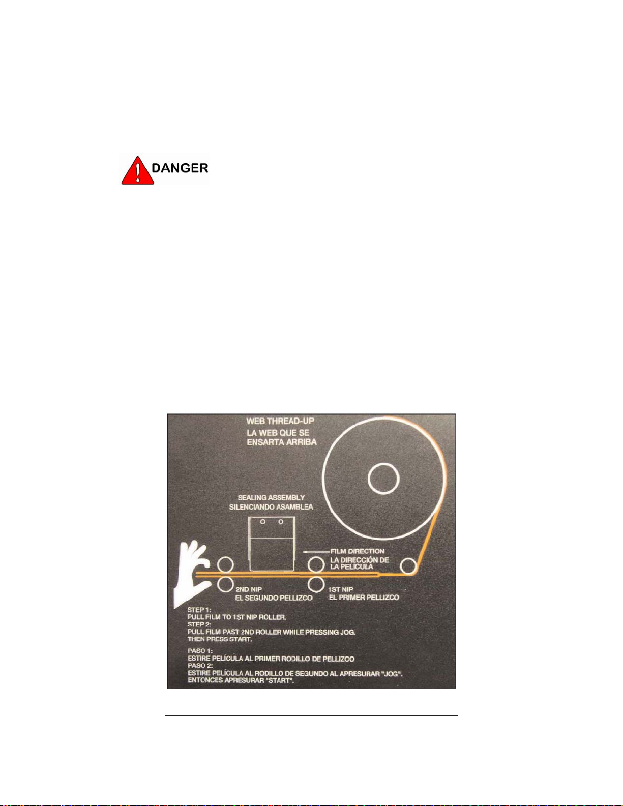
2. Route the film web around the bottom of the
film roller. See Figure 1.
3. Slide the unsealed edge slot of the film over
the air injection tube, up to the outfeed nip
(first) rubber rollers.
5. Touch the JOG button until the end of the film
is fed through the sealing section, slitter, outfeed end nip and belt rollers.
The film has a tendency to bunch up on the
slitter blade. The film must be pulled through
the machine by hand while pressing the JOG
button.
NOTE: Refer to the Operator Controls instruc-
tion for touch screen operation.
Figure 1
Film Web Thread-Up
Page 13
8. Press the START button to create air cushions.
6. Touch the top line button to change to the
desired operating mode:
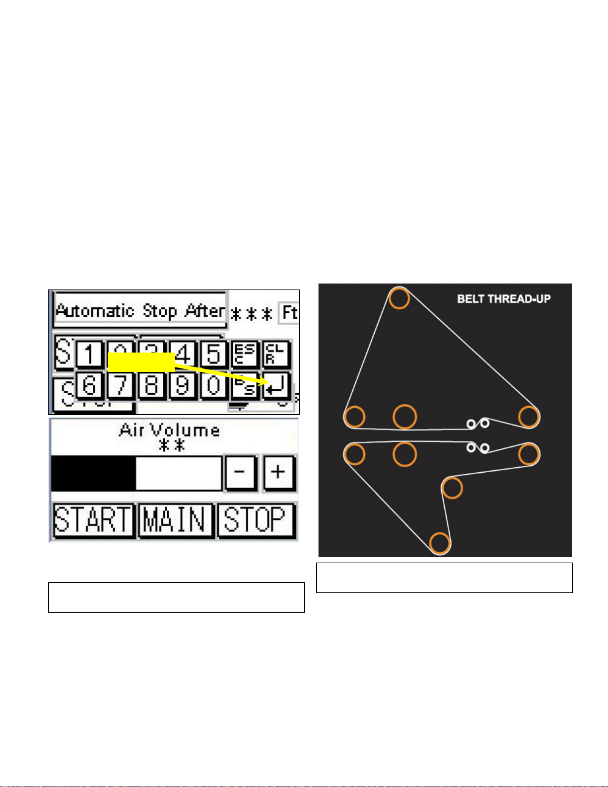
Set the air volume, by touching the “AIR” button.
The screen will change to “Air Volume” screen
(Fig.2). Adjust air volume by using the + or –
Normal Operation starts and runs film con-
buttons.
tinuously until a stop is pressed.
Automatic Stop after *** ft runs an amount of
film, set by the operator, and then stops.
Fill Basket With *** ft uses optional
sensors in a basket or bin to start/stop as
required to keep the bin full.
NOTE: To test for proper inflation of cushions,
gently squeeze cushion with both hands
while viewing it from the perf edge.
There should be a 0.75"-1.0" gap
between the forefinger and thumb on
both hands.
7. If the Automatic Stop mode is selected, touch
the area on the screen *** Ft. Screen will
change to a key board. Select length and touch
the enter key.(Bent Arrow Key)
9. Press the STOP button to stop the machine.
Enter Key
Fig. 2
Belt Thread – Up Diagram
Cushion Inflation Volume
Fig. 3
Page 14
SEALING BELT REPLACEMENT
PREGIS AIRSPEED 5000
AIR CUSHION MACHINE
Introduction
Expected sealing belt life is approximately 100-200
hours (9,000-18,000 meters). The upper belt will
wear faster than the lower belt due to sealing wire
Electrical shock or unexpected machine
movement can cause injury. DO NOT operate
machine with guards re moved or covers
open.
contact. To extend belt life by up to 20%, each belt
may be flipped around as explained in the following description.
After both edges of the upper belt are completely
worn through, transfer the lower belt to upper belt
position. Discard the worn out upper belt. Install
a new lower belt. The belt transferred to the upper
position is again put through the same cycle of use.
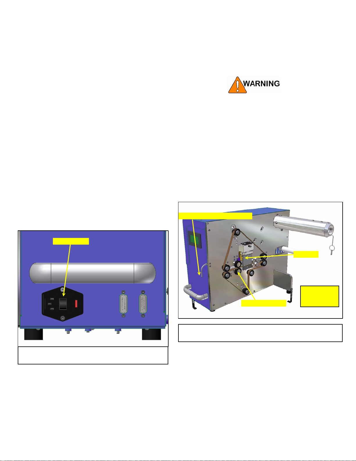
On/Off Switch
For your safety, follow your company’s
lockout/tagout policy as required for each
task.
To replace the sealing belt(s):
Outfeed Nip Roller Open/Close
See Fig . 3
Do Not Operate
with Guards
Outfeed Nip Roller
Removed
Infeed End
Belt Replacement
Fig. 2
Outfeed End
Fig. 1
Page 15
Turn both nip Open/Close levers up to open
the belt drive nips. See Figures 1 and 2.
1. Remove the front upper and lower guard cov-
ers by removing the fasteners.
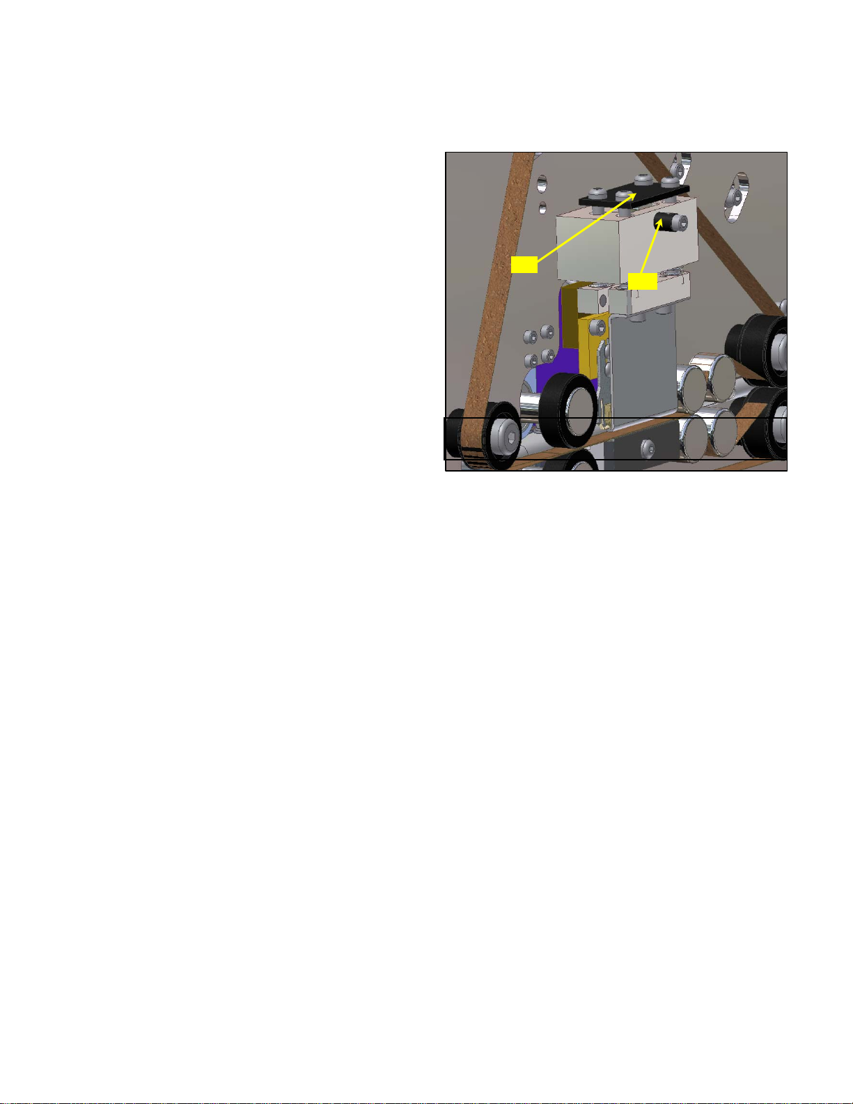
2. Lift the upper guard/clamp and seal wire
assembly off the lower clamp block and platen, while turning the cam shaft. Turn the shaft
until the high side of the cam is at the top,
holding the guard/clamp and seal wire assembly up. See Figure 3.
3. For both the upper and lower belt, push the
tensioner roll to create the slack required to
remove the sealing belt. See Figures 2 and 4.
4. Remove the belts from between both sets of
nip wheels and the infeed side belt diverter
rollers. See Figure 4.
5. Remove the sealing belts.
6. Install the belts between the outfeed nip wh eels
and the infeed side belt diverter rollers. Use
belt thread-up diagram if needed.
Cam
Shaft
Fig. 3
block and platen. See Figure 3.
Seal Wire Lift Cam
9. Turn nip Open/Close lever down to close
the tape drive nips. See Figures 1 and 2.
10. Install the front upper and lower guard covers
with fasteners.
11. Set the air cushion machine power to ON with
the switch. See Figure 1.
7. For each sealing belt, push the associated ten-
sioner roller inward, collapsing its spring, to
allow the sealing belt to be fitted around all
rollers. See Figures 2 and 4.
8. 10. Lift the upper guard/clamp and seal wire
assembly while turning the cam shaft. Turn
the shaft until the low side of the cam is at the
top, allowing the guard/clamp and seal wire
assembly to drop down onto the lower clamp
Page 16
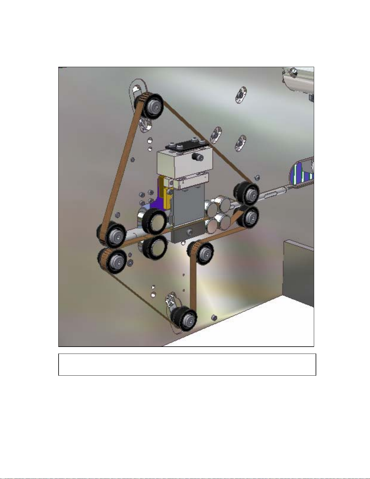
Fig .4
Seal Belt Routing
Page 17

MAINTENANCE SCHEDULE
PREGIS AIRSPEED 5000
AIR CUSHION MACHINE
Monthly Maintenance
Electrical shock or unexpected machine
movement can cause serious injury or
death. For your safety, follow your company’s lockout/tagout policy as required for
each task.
Daily Maintenance
1. Check the condition of the sealing belts, transport rollers, and nip rollers. Flip or replace
belts if worn 75% through, or if the splice is
peeling or pulling apart more than 0.03" (0.76
mm).
Weekly Maintenance
1. Clean the sealing belts, guide rollers, nip
rollers, seal wire, lower platen, slitter blade,
and counter wheel of any contamination
and/or debris.
2. Ensure that all parts turn freely, including all
belt rollers, the film dancer roller and pivot
shaft, and the unwind shaft (with brake off).
1. Check all components for excessive wear,
including the nip plastic drive gears, rubber
nip rollers, and the slitter blade.
2. Check fasteners for looseness.
3. Clean the blower of any debris.
4. Check the alignment of the seal wire with the
platen and the upper guard/clamp with the
lower block.
5. Inspect the sealing surface (green) of the lower
platen for wear and replace if necessary.
Semi-Annual Maintenance
1. Apply axle grease (Exxon Ronex MPTM or
equivalent) to the face of nip actuation cams.
Also apply grease to the mating surfaces
where the cams contact and actuate the upper
rollers of the outfeed nips.
NOTE: Refer to the Introduction instruction for
the lubrication location.
3. Ensure the unwind shaft brake mechanism
works properly. The brake must be able to go
from totally free to a tight grip on the shaft.
Page 18

TROUBLESHOOTING
PREGIS AIRSPEED 5000
AIR CUSHION MACHINE
Cause: Insufficient injection air.
Electrical shock or unexpected machine
movement can cause serious injury or
death. For your safety, follow your company’s lockout/tagout policy as required for
each task.
1. Problem: Machine will not start.
Cause: Machine not set-up properly.
Solution: Turn power ON.
Press RESET button.
Press START button.
Read message at top of screen.
Text will read Ready to Run,
Paused, or Running.
Solution: Check if air injector tube is plugged
or disconnected.
Check if blower is operating
properly.
Cause: Poor quality seal or no seals.
Solution: Refer to Problem 5 Solutions.
Cause: Too much air in cushion blows seals
open.
Solution: Reduce the inflation volume from
“air Volume” screen.
NOTE: To test for proper inflation of cushions,
gently squeeze cushion with both hands
while viewing it from the perf edge.
There should be a 0.75"-1.0" gap
between the forefinger and thumb on
both hands.
Thread up film so encoder
wheel turns. Machine will not run
more than a few seconds if the
counter wheel does not turn.
2. Problem: Cushion does not inflate.
Cause: Machine not ready.
Solution: Jogging machine will not start
inflation, use START button.
Increase Air Volume, as required
for c u s h i o n s i z e being run.
3. Problem: Film jams.
Cause: Cushion release slit not being cut
properly.
Solution: Clean or replace the slitter blade.
Cause: The operator is not pulling the film
through the machine while pressing
the JOG button for web thread-up.
Solution: During film thread-up, pull the film
past the slitter while pressing the
JOG button.
Cause: Film burn through.
Solution: Turn down the sealing temperature.
Page 19

3. Problem: Film jams. (Cont’d.)
Cause: Film or belts not being pulled.
Cause: Film not being pulled evenly.
Solution: Ensure t h e i n f e e d nips are closed.
Cause: Film slipping.
Solution: Check nip wheels and sealing belts
for contamination and clean as
necessary.
Check that the unwind shaft brake
system releases and the parent roll
turns freely.
Cause: Gap in film is too small for air
injector tube.
Solution: Replace the roll of film if the gap is
smaller than 0.56"
Cause: Film waste clogging slitter.
Solution: Remove melted film and waste from
knife area.
Solution: Ensure the outfeed nips are closed
comp l e t e l y . The rubber nip rollers
should compress together re sulting in
a 0.38" flat spot between them.
Ensure all seal belt idlers turn freely.
Cause: Film slipping.
Solution: Check nip wheels and sealing belts
for contamination and clean as
necessary.
Cause: Gap in film is too small for air
injector tube.
Solution: Replace roll of film.
Cause: Counter wheel not operating.
Solution: Check if counter wheel is against
air injection tube.
Check if wheel traction o-ring is
worn or missing.
4. Problem: No film movement.
Cause: Film is not properly positioned in
machine.
Solution: Thread the film as per the thread-up
diagram label on the side of the
machine. Lightly pull the leading
edge of the film through the
machine, past the slitter and outfeed
nip, while jogging. The film must
be taut before pressing START.
5. Problem: Poor quality seal or no seals. Cause: Sealing wire broken.
Check if flat spring is holding wheel
firmly against air injection tube.
Check if air injection tube is bent,
not allowing counter wheel to make
proper contact.
Check if the proximity sensor is
close enough to the wheel to switch
on and off as the wheel turns.
Page 20

Solution: Replace the sealing wire.
NOTE: Allow the seals to cool for approxi-
mately one minute before testing.
Cause: Sealing wire not hot enough.
Solution: Adjust the sealing tempera ture.
Cause: Air pressure blowing out seals.
Solution: Decrease the inflation air pressure
to prevent over inflating.
Check that the upper guard/clamp is
seated properly on lower block, isolating the seal from inflation.
Check that the lower platen is
pivoting properly.
Check that the lower platen stiff,
outer plastic (DuritTM) sealing surface is securely mounted to the
lower layer of soft silicone.
6. Problem: Main screen “Ready To Run” mes-
sage replaced with “Change Belts” message.
Cause: Belt Odometer screen has reached
the preset belt change interval
value.
Solution: Replace the sealing belt(s) and have
Management reset the Actual value
on the Belt Odometer screen to
zero (0) meters.
NOTE: Refer to the Sealing Belt Replacement
instruction for more information.
Ensure both nips are fully closed. It
is critical that the outfeed nip is providing the proper nip pressure on
the seal.
Cause: Film not held tight together between
sealing belts.
Solution: Check to ensure the upper
guard/clamp is lowered/closed.
Cause: Sealing belts are worn.
Solution: Replace sealing belts as necessary.
Page 21

 Loading...