

Prefect Control PRE9200, PRE9220, PRE9250, PRE9280 Installation Instructions Manual
Prefect Instructions
1
Prefect Control Ltd Unit 2, Church Field Business Park, Church Field Road, Sudbury, Suffolk, CO10 2YF
Tel: 01787 320 604 Fax: 0845 450 3020 Email: mail@prefectcontrols.com Website: www.prefectcontrols.com
Due to our policy of continuous improvement, we reserve the right to change specifications without notice
V1.1
IN-146
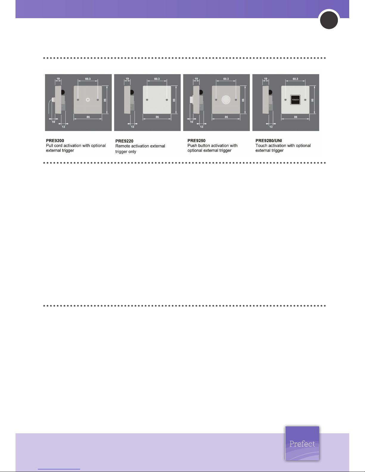
PRE9200, 9220, 9250, 9280UNI Run Back Timers
The PRE9200 series of time delay switches are designed to
provide timed control of lighting, heating or ventilation loads.
Using push button, touch (light press required), pull cord or
remote activation, the user can switch on a load for a preset
time period and have the load turn off automatically after the
time period has elapsed.
Multiple timing ranges come as standard to allow the time out
period to be set accurately. Time setting is achieved using
switches and a thumbwheel at the rear of the unit.
Several modes of operation are selectable using the switches:
• ON/OFF mode: Activating the timer will turn on the load and
start the timing. Activating the timer again during a timer run
will immediately turn off the load and stop the time run.when
a 230v trigger voltage is applied to the TRIG terminal the timer
will start. Disconnecting then reconnecting the trigger voltage
will then stop the timer.
• Resetting mode: activating the timer will turn on the load
and start the time run. Activating the timer again during an
exsisting time run will re-start the time run period from scratch.
When using an external trigger in this mode, the timer will not
start until the trigger is removed making it ideal for pump or
fan overrun applications.
• Non-resetting: Activating the timer will turn on the load and
start the time run. Triggering the timer again during a time
run will have no effect. Applying a 230v trigger to the TRIG
terminal will start the time run. whether the voltage remains or
is disconected the time run will complete.
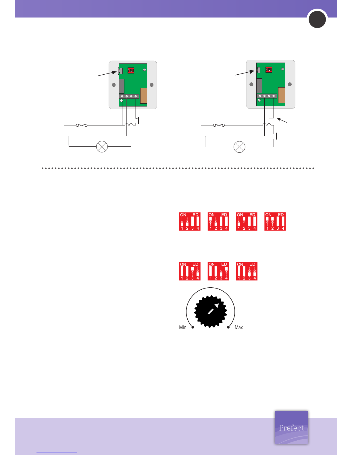
Operation:
Wire the PRE9200 timers as in diagram 1. Connection to the
TRIG terminal is optional on all units except the PRE9220 remote
timer. Applying a live to the trigger terminal will start the timer
running. A momentary switch can be used, for example, in
corridor lighting applications. A permanent input can be used,
for example, in pump overrun applications.
To switch from more than one position simply wire two or more
units in parallel to achieve two way and intermediate switching,
or use the trigger terminal with a slave switch.
For lighting applications that call for the replacement of a three
wire switching system follow diagram 2. When installing touch
switches do not fix to a vibrating or uneven surface.
Installation Instructions:
Prefect Instructions
2
Prefect Control Ltd Unit 2, Church Field Business Park, Church Field Road, Sudbury, Suffolk, CO10 2YF
Tel: 01787 320 604 Fax: 0845 450 3020 Email: mail@prefectcontrols.com Website: www.prefectcontrols.com
Due to our policy of continuous improvement, we reserve the right to change specifications without notice
V1.1
IN-146
Installation Instructions Continued...
WARNING. This device works at mains potential. Be sure to take
care when working with electricity. Ensure all work complies
with relevant regulations in force at time of installation.
1. Perform safe ilsoation procedure of the appropriate cicuits
2. Connect the timer to the conductors
Live supply to the L terminal
Neutral to the N terminal
Load to the LIVE OUT terminal
Where required connect the external trigger to the TRIG
terminal.
3. Set the timing range according to the diagram opposite. For
example; if a timmming range of 100 minutes is required set
the switches to; 1 to 2 hours.
4. Set the thumb wheel to the precise time setting. the
thumbwheel adjusts between the time settings set by the
switches. Following the example above the wheel would need
to be set to a 2 o’clock position.
5. Double check all connections are correct & firmly fitted.
6. Ensuring the cabaling is not in a position to become damaged
fit the unit to the box
7. When safe to do so, switch the mains supply back on at the
distribution board.
Installation & Settings:
Diagram 1 Diagram 2
LOAD: 16 Amp resistive load 10 Amp incandescent lighting 6 Amp
fluorescent lighting 3 Amp compact fluorescent lighting 3 Amp
low energy lighting. 3 Amp low voltage lighting (switch primary of
transformer) Fluorescent lighting (max 6 fittings recommended). For
fluorescent lighting total power factor correction capacitance must
not exceed 40μF. 3 Amp fans and ventilation equipment . Switch
SON lighting loads via a contactor
SUPPLY VOLTAGE: 220-240 Volts AC 50 Hz
TIMING PERIOD: Adjustable 1 second to 2 hours in ranges
FIXING METHOD: Surface fixing 25mm deep plastic surface mount
moulded box. Flush fixing 25mm steel wall box or 32mm deep
cavity wall box.NOTE: When using a metal box ensure the top and
bottom lugs are removed from the box.
TERMINAL CAPACITY: 4.0mm2
MATERIAL: Flame retardant ABS
TYPE: Class 2
TEMPERATURE: -10°C to 35°C CONFORMITY EMC-89/336/EEC
TIMING
ADJUSTMENT
LIVE IN
NEUTRAL
LOAD
CIRCUIT PROTECTION
(IF REQUIRED)
SLAVE TRIGGER
LINK
43
ON
TIME
21
L
N
LIVE
OUT
TRIG
TIMING
ADJUSTMENT
LIVE IN
NEUTRAL
LOAD
CIRCUIT PROTECTION
(IF REQUIRED)
SLAVE TRIGGER
43
ON
TIME
21
L
N
LIVE
OUT
TRIG
1hour2hours
1sec5mins
15mins1hour
5mins15mins
Resetting
mode
non-resetting
mode
on/off
mode
The timming wheel selects
the run time. Clockwise turn
increases time, anti-clockwise
decreases time.
 Loading...