

Prefect Control PRE9275 Installation Instructions Manual

Prefect Instructions
1
Prefect Control Ltd Unit 2, Church Field Business Park, Church Field Road, Sudbury, Suffolk, CO10 2YF
Tel: 01787 320 604 Fax: 0845 450 3020 Email: mail@prefectcontrols.com Website: www.prefectcontrols.com
Due to our policy of continuous improvement, we reserve the right to change specifications without notice
V1
23.09.2015
IN-131
PRE9275 Hob Run Timer
The PRE9275 Hob re-set switch has been designed to limit
wasteful use of energy, whilst reducing the potential risk of pan
fires by allowing the electric hob fitted in kitchens to run for only
15 or 30 minutes.
After the 15 or 30 minutes has elapsed, the control can be
re-activated for a further period.
The PRE9275 is fitted with a single “non latching” push button,
on activation the PRE9275 will allow power to flow to the hob
for a period of 15 or 30 minutes, indicated by
the “Active LED”.
After this time period the supply is disconnected.
Operation:
WARNING. This device works at mains potential. Be sure to take
care when working with electricity.
1. If fitting to a metal back box ensure that top and bottom lugs
are removed.
2. Isolate the mains supply to the circuit at the main consumer
unit.
3. Perform safe isolation procedure
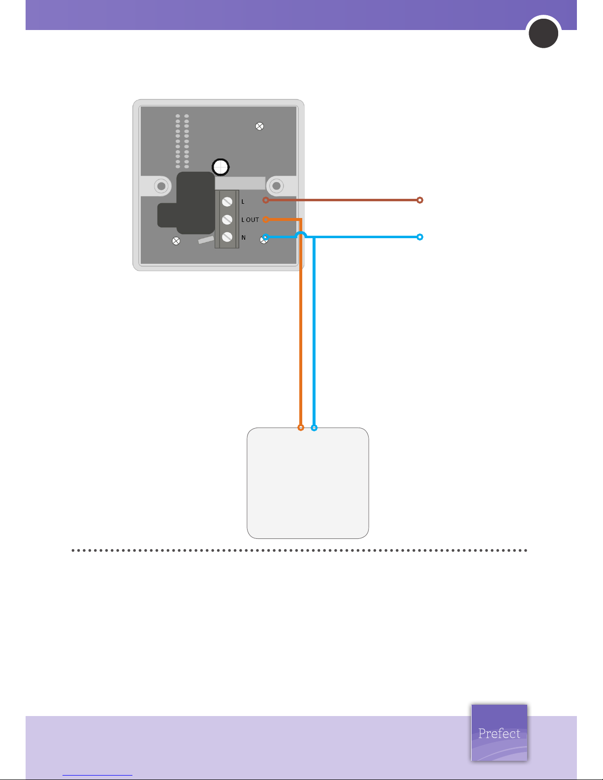
4. Connect the PRE9275 in the following manner: connect Live
supply to the L terminal, the load to the LIVE OUT terminal and
Neutral to the N terminal.
5. Fix the unit to a 45mm or greater surface or sunken back
box, take care not to over tighten the mounting screws, over
tightening of these screws may deform the facia resulting in
the activation button becoming tight or seized.
6. It is strongly recommended that when the unit is mounted to a
smooth surface, for example an acrylic splash back panel, that
a thin bead of silicon is applied around the product. This is
highly recommended as the silicone will protect against water
or over substance ingress, the silicone bead will also stabilise
the unit when mounted onto a smooth surface, as when
fitted to such a surface the product me become moderately
movable.
7. Switch the mains supply back on at the distribution board.
8. Press the activation button and ensure the button moves
freely, ensure the load is functional.
9. Cancel the current cycle by pressing the activation button.
IMPORTANT NOTICE! This device should be installed by a qualified
electrician in accordance with the latest edition of the IEE wiring.
Installation Instructions:
Prefect
PRE9276
Hob
Re-set
Active
Prefect
PRE9275
Hob
Re-set
Active
NOTICE: If the PRE9275 does not complete the desired time run, this may be due to transient volt drop. When transient volt drop caused
by lighting, ventilation equipment, neon indicators or other, the resulting volt drop may reset the unit if below the minimum operation
voltage of 216.2VAC. If this problem occurs fit a PRESCX21uF smoothing capacitor between the Live in and Neutral terminals of the
PRE9275. Do not fit more than one capacitor to the hob circuit, only fit the capacitor to the PRE9275, do not terminate the capacitor to any
other parts of the hob circuit.
Prefect Instructions
2
Prefect Control Ltd Unit 2, Church Field Business Park, Church Field Road, Sudbury, Suffolk, CO10 2YF
Tel: 01787 320 604 Fax: 0845 450 3020 Email: mail@prefectcontrols.com Website: www.prefectcontrols.com
Due to our policy of continuous improvement, we reserve the right to change specifications without notice
V1
23.09.2015
IN-131
Specication:
LOAD: 26 Amp resistive load maximum
SUPPLY VOLTAGE: 216.2-253 Volts AC 50 Hz
TIME OUT PERIOD: 15 or 30 mins selectable only at point of order
FIXING METHOD: Surface fixing 45mm deep plastic surface mount
moulded box. Flush fixing 45mm steel wall box or 32mm deep
cavity wall box.
TERMINAL CAPACITY: 4.0mm
2
MATERIAL: Flame retardant ABS Class 2
TYPE: Class 2
TEMPERATURE: -10˚C to 35˚C
CONFORMITY: EMC-89/336/EEC. LVD-73/23/EEC
WE RECOMMEND THIS PRODUCT BE INSTALLED BY
A COMPETENT PERSON IN ACCORDANCE WITH IEE
REGULATIONS IN FORCE AT THE TIME.
LOAD
27A Resistive load
up to 6.2kW
Mains
Supply
Rear view of unit
Wiring Diagram:
 Loading...