

Preen AFV-P Series, AFV-P-600, AFV-P-1250, AFV-P-2500, AFV-P-5000 User Manual

AFV-P Series
Programmable AC & DC Power Supply
User Manual
AC Power Corp. (Preen)
V 1.05.01EN
The information in this document is subject to change without notice.
© AC Power Corp. (Preen). All rights reserved

Contents
Legal Notices
The information in this product manual is subject to change without notice.
AC Power Corp. makes no warranty of any kind with regard to this user manual, including, but not limited to, the implied warranties of merchantability and fitness for
a particular purpose. AC Power Corp. shall not be held liable for errors contained
herein or direct, indirect, special, incidental or consequential damages in connection
with the furnishing, performance, or use of this material.
Copyright Notices. Copyright 2017 AC Power Corp. (Preen), all rights reserved. Reproduction, adaptation, or translation of this document without prior written permission is prohibited, except as allowed under the copyright laws.

Contents
Warranty
Preen’s AFV-P series is warranted against defects in material and workmanship for a
period of two year after date of shipment. Preen agrees to repair or replace any assembly or component found to be defective, under normal use during this period.
Preen’s obligation under this warranty is limited solely to repairing any such product
which in sole Preen’s opinion proves to be defective within the scope of the warranty when returned to the factory or to an authorized service center. Transportation to
the factory or service center is to be prepaid by the purchaser. Shipment should not
be made without prior authorization by Preen.
This warranty does not apply to any products repaired or altered by persons not authorized by Preen, or not in accordance with instructions furnished by Preen. If the
product is defective as a result of misuse, improper repair, or abnormal conditions or
operations, repairs will be billed at cost.
Preen assumes no responsibility for its product being used in a hazardous or dangerous manner either alone or in conjunction with other equipment. High voltage
used in some products may be dangerous if misused. Special disclaimers apply to
these products. Preen assumes no liability for secondary charges or consequential
damages and in any event, Preen’s liability for breach of warranty under any contract or otherwise, shall not exceed the purchase price of the specific product
shipped and against which a claim is made.
Any recommendations made by Preen for use of its products are based upon tests
believed to be reliable, but Preen makes no warranty of the results to be obtained.
This warranty is in lieu of all other warranties, expressed or implied, and no representative or person is authorized to represent or assume for Preen any liability in
connection with the sale of our products other than set forth herein.
AC Power Corp. (Preen)
USA
192 Technology Dr., Suite S, Irvine, CA 92618
TEL +1 949-988-7799
Taipei
3F No. 200 Gangqian Road, Neihu Dist., Taipei 114, Taiwan
TEL +886 2-2627-1899 FAX +886 2-2627-1879

Contents
SAFETY SUMMARY
The following general safety precautions must be observed during all phases of operation, service, and repair of this product. Failure to comply with these precautions
or specific WARNINGS given elsewhere in this manual will violate safety standards of
design, manufacture, and intended use of the product.
Preen assumes no liability for the customer‘s failure to comply with these requirements.
BEFORE APPLYING POWER
Verify that the product is set to match with the power line input.
PROTECTIVE GROUNDING
Make sure to connect the product to the protective ground to prevent an electric
shock before turning on the power.
NECESSITY OF PROTECTIVE GROUNDING
Never cut off the internal or external protective grounding wire, or disconnect the
wiring of protective grounding terminal. Doing so will cause a potential shock hazard
that may bring injury to a person.
DO NOT OPERATE IN AN EXPLOSIVE ATMOSPHERE
Do not operate the product in the presence of flammable gases or fumes.
DO NOT REMOVE THE COVER OF THE PRODUCT
Personnel who operate the product must not remove the cover of the product.
Component replacement and internal adjustment can be done only by qualified service personnel.
WARNING
LETHAL VOLTAGES. The product can supply 440V peak at its output. DEATH on
contact may result if either the output terminals or the output circuits connected
to the output are touched when the product output is on.

Contents
Table of Contents
1 GENERAL INFORMATION ............................................................................................... 1
1.1 Introduction .................................................................................................... 1
1.2 Key Features .................................................................................................... 2
1.3 Specifications .................................................................................................. 3
1.4 Exterior ........................................................................................................... 5
1.5 Name of Parts ................................................................................................. 6
2 INSTALLATION .................................................................................................................. 9
2.1 Inspection ....................................................................................................... 9
2.2 User Preparation ............................................................................................. 9
2.3 Input Connection ............................................................................................. 9
2.4 Output Connection ......................................................................................... 10
2.5 Remote Sense Connection .............................................................................. 11
2.6 Power-on Procedures ..................................................................................... 12
2.7 Product Handle Installation ............................................................................ 13
2.8 Interface Card Installation .............................................................................. 13
2.8.1 RS232/RS485 9-Pin D-Type Connector ....................................................................... 14
2.8.2 PLC Remote In & Out Connector ................................................................................ 14
3 LOCAL OPERATION ....................................................................................................... 16
3.1 General .......................................................................................................... 16
3.2 Operation via the Touch Screen and the Rotary Knob ............................................. 16
3.3 MAIN Page ..................................................................................................... 18
3.3.1 Output Voltage Range ................................................................................................. 19
3.4 MENU Page .................................................................................................... 20
3.5 SETTINGS Page ............................................................................................... 21
3.5.1 TESTING Subpage (ADVANCED Mode) ........................................................................ 21
3.5.2 TESTING Subpage (BASIC Mode) ................................................................................ 31
3.5.3 SYSTEM Subpage ......................................................................................................... 37
3.6 COMMUNICATION Page .................................................................................. 43
3.6.1 ETHERNET Subpage .................................................................................................... 43

Contents
3.6.2 GENERAL Subpage ...................................................................................................... 44
3.6.3 GENERAL Subpage with GPIB interface (optional) ..................................................... 45
3.7 RESULTS Page ................................................................................................. 46
3.8 WAVE Page ..................................................................................................... 47
3.9 METER Page ................................................................................................... 49
3.10 INFORMATION Page...................................................................................... 51
3.11 Protection .................................................................................................... 52
4 CALIBRATION ................................................................................................................. 54
4.1 HI-Range Voltage 310V ................................................................................... 56
4.2 LO-Range Voltage 155V .................................................................................. 57
4.3 HI-Range Voltage 60V ..................................................................................... 58
4.4 LO-Range Voltage 60V .................................................................................... 59
4.5 HI-Range RMS Current .................................................................................... 62
4.6 LO-Range RMS Current ................................................................................... 63
4.7 Peak Current .................................................................................................. 64
4.8 Output Socket Current (Specialize for AFV-P-5000) .......................................... 66
5 PROGRAMMABLE FEATURES .................................................................................... 68
5.1 General .......................................................................................................... 68
5.2 STEP Feature .................................................................................................. 72
5.3 RAMP Feature ................................................................................................ 82
5.4 TRANSIENT Feature ........................................................................................ 84
6 THEORY OF OPERATION ............................................................................................. 87
7 REMOTE OPERATION ................................................................................................... 88
7.1 General .......................................................................................................... 88
7.2 Remote Control Software: General Mode ....................................................... 90
7.3 Remote Control Software: Program Mode ...................................................... 93
7.4 Remote Control Software: Additional Features ............................................... 95

AFV-P Series User Manual
1
1 General Information
1.1 Introduction
Preen’s AFV-P series is a programmable AC power supply with DC output and precision measurements. This compact power supply comes in four power levels, 600VA,
1250VA, 2500VA and 5000VA, which provides stable output voltage and output frequency with low distortion. The PWM design of power stage allows for full
volt-ampere into loads. The front panel has both touch screen and rotary knob for
setting the product output, which provide an easy operation and measurement
reading display. Remote control for the product can be accomplished selectively via
RS232, RS485, Ethernet, USB or GPIB.
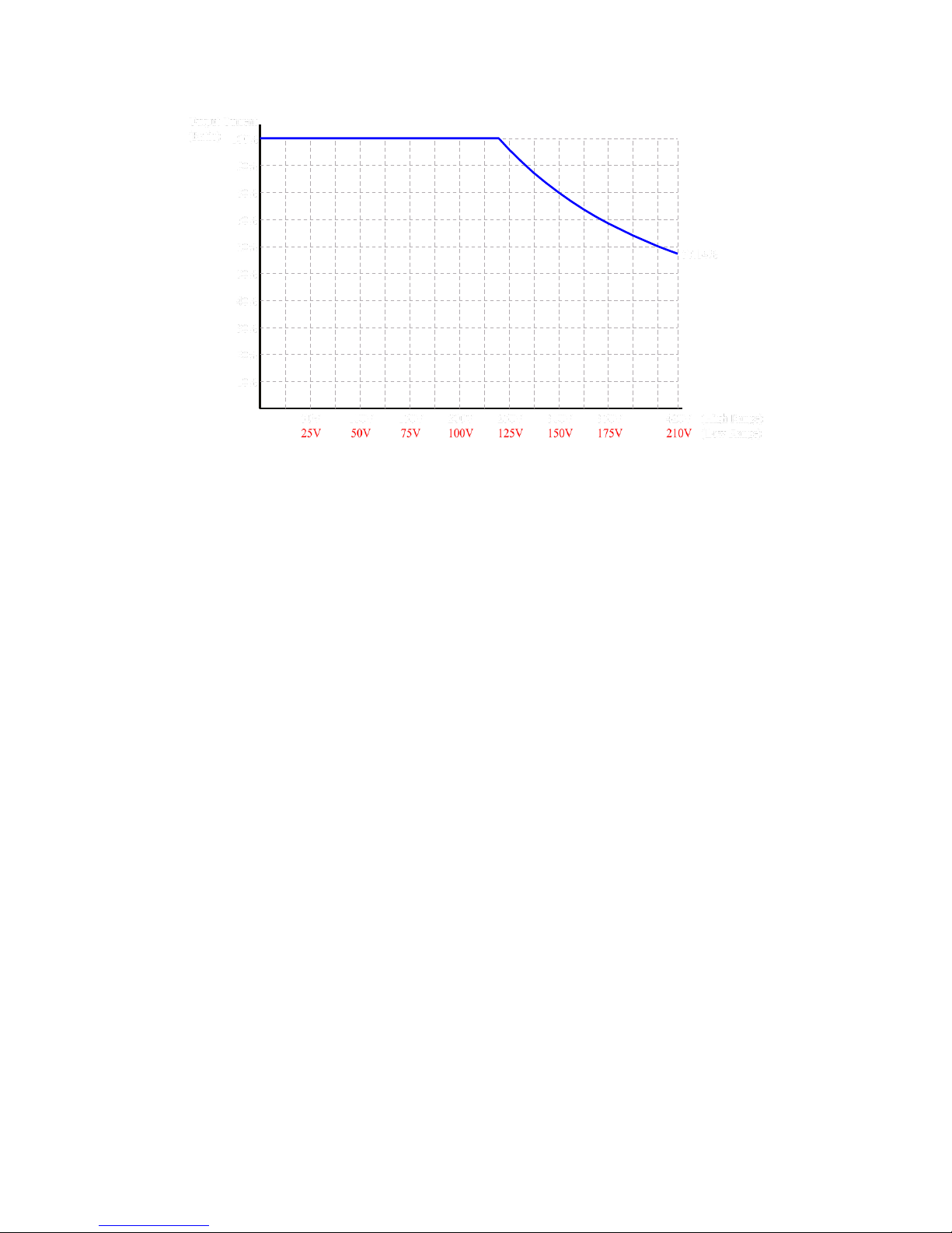
The following figures show the V/I curve according to the AC & DC output of the
product, which can be applied to any product model and any output voltage range of
the product.
Figure 1.1 V/I curve for the AC output of the product
NOTICE
If the Power Factor (PF) corresponding to the AC output is less than 0.65, 100%
output current can be achieved under 0%-100% output voltage, which can be ap-
plied to any product model and any output voltage range of the product.
AFV-P Series User Manual
2
Figure 1.2 V/I curve for the DC output of the product
1.2 Key Features
A. Configuration
1. Local operation via the touch screen and the rotary knob on the front panel.
2. Remote control via RS232, RS485, Ethernet, USB or GPIB.
3. Protection for OVP, LVP, OCP, OPP, OTP, RCP, Fan Fail and AMP Fail.
4. Temperature-controlled fan speed.
B. Input / Output
1. Selective output voltage range with full scale 310V/Auto.
2. Universal input voltage range 98~132VAC/196~264VAC.
3. Wide output voltage from 0 to 310VAC & output frequency from 15 to 1000Hz.
4. Measurement readings of V, I, P, VA , VAR, f, Ipk, CF and PF.
5. Output of Synchronized signal.
AFV-P Series User Manual
3
1.3 Specifications
Technical specifications of product are listed below. All specifications have been
tested according to Preen’s standard test procedures.
Model
AFV-P-600
AFV-P-1250
AFV-P-2500
AFV-P-5000
AC Input
Phase
Single
Input Voltage Range
98-132Vac/196-264Vac
196-264Vac/175-235Vac
Input Frequency
47~63Hz
Max. Current
10A
20A
20A
40A
AC Output
Power (VA)
600VA
1250VA
2500VA
5000VA
Power (W)
500W
1000W
2000W
4000W
Phase
1ϕ /2 Wire + G
Voltage Range
0-155V
rms
/0-310V
rms
Voltage Resolution
0.1V
rms
Frequency
40-500Hz (opt. 15-1000Hz)
Frequency
Resolution
0.1Hz, at 15-100Hz; 1Hz, at 100-1000Hz
Max. Current (RMS)
5A/2.5A
10A/5A
20A/10A
40A/20A
Max. Current (Peak)
22.5A/11.3A
45A/22.5A
90A/45A
180A/90A
Total Harmonic
Distortion (THD)
0.3%, at 40-100Hz; 0.5%, at 101-500Hz; 0.8%, at 501-1000Hz
(Resistive Load)
Line Regulation
0.1V
Load Regulation
0.07% F.S (Resistive Load)
Response Time
300s
Crest Factor
3
Inrush Current
4.5 peak current/RMS current
DC Output
Power
300W
600W
1250W
2500W
Voltage Range
0-210V/0-420V
Max. Current
2.5A/1.25A
5A/2.5A
10A/5A
20A/10A
Ripple & Noise (RMS)
0.15%
0.24%
Measurement
Voltage Range
0-420V
Voltage Accuracy
(0.2% of Reading + 5 Counts)
Voltage Resolution
0.1V
AFV-P Series User Manual
4
Frequency Range
15-1000Hz
Frequency Accuracy
0.1Hz at 40-500Hz;
0.2Hz at 501-1000Hz
Frequency Resolution
0.1Hz
Current Range
Hi: 1-12A/
Lo: 0.005-1.2A
Hi: 2-24A/
Lo: 0.005-2.4A
Hi: 0.05-48A
Current Accuracy
(1% of Reading + 5 Counts), at 40-500Hz;
(1% of Reading + 10 Counts), at 501-1000Hz
Current Resolution
Hi: 0.01A/Lo: 0.001A
Hi: 0.01A
Peak Current Range
0-45A
0-90A
0-180A
Peak Current Accuracy
(1% of Reading + 5 Counts), at 40-500Hz;
(1% of Reading + 10 Counts), at 501-1000Hz
Peak Current Resolution
0.1A
Power Range
Hi: 100-1200W/
Lo: 0-120W
Hi: 200-2400W/
Lo: 0-240W
Hi: 0-4800W
Power Accuracy
(2% of Reading + 10 Counts), at 40-500Hz;
(2% of Reading + 15 Counts), at 501-1000Hz
Power Resolution
Hi: 1W/Lo: 0.1W
Hi: 1W
General
Efficiency
77% at Max. Power
80% at Max. Power
Protection
OVP, LVP, OCP, OPP, OTP, RCP, Fan Fail and AMP Fail
Remote Interface
Standard: RS232/RS485/Ethernet/USB/PLC Remote In & Out;
Option: GPIB/Analog Control
Over Current Foldback
Constant Current (CC) Mode
Synchronized Signal
ON Mode (5V DC Signal) or EVENT Mode (5V DC Pulse Signal)
Memories
50 Memory Sets & 1200 Steps (24 Steps/Memory Set)
Operating Temperature
0-40C
Dimensions
(H×W×D) (mm3)
89×442×450
89×442×600
222.5×442×600
Weight
Approx. 16kg
Approx. 20kg
Approx. 31.3kg
Approx. 70kg
All specifications are subject to change without notice
Table 1.1 Technical specifications
AFV-P Series User Manual
5
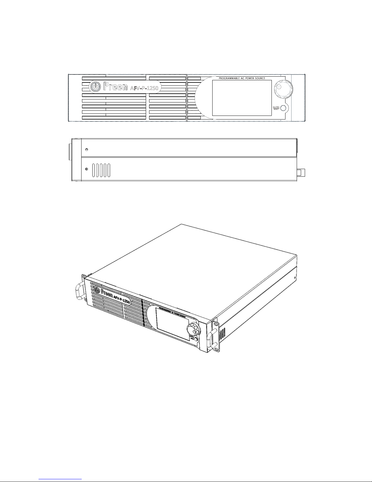
1.4 Exterior
Product exterior of the AFV-P series are given as follows,
(a) Front-side view of the AFV-P series.
(b) Right-side view of the AFV-P series.
Figure 1.3 Product exterior of the AFV-P series
Figure 1.4 Product exterior of the AFV-P series in axis-side view

AFV-P Series User Manual
6
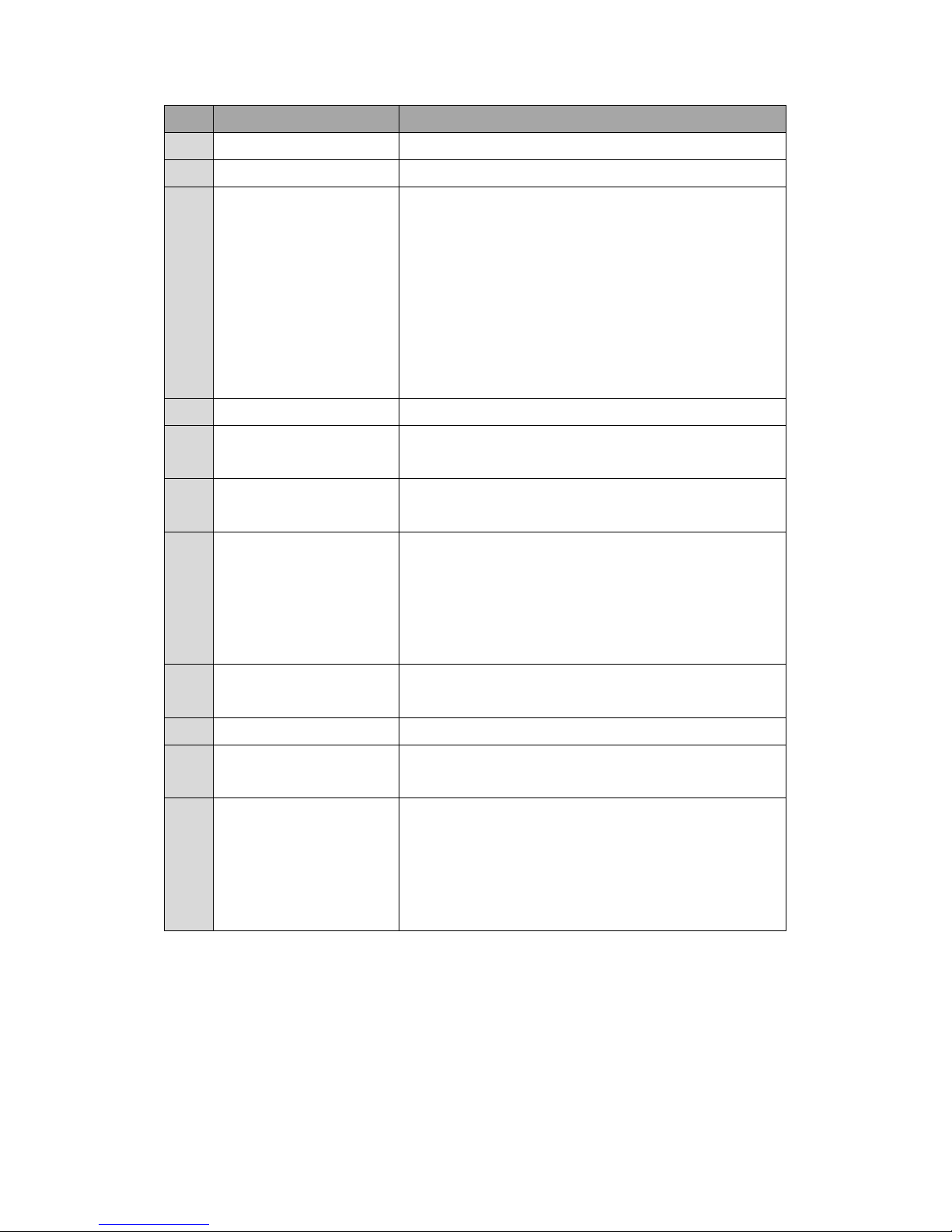
1.5 Name of Parts
A. Front Panel
Figure 1.5 Front panel
Item
Name
Description
1
Power Switch
Press this switch to turn on/ turn off the product.
2
Touch Screen
Input programming data or options by manipulating the
touch screen to the desired one.
3
Rotary Knob
Input programming data or options by turning the rotary
knob to the desired one.
4
Output & Reset Button
Press this button to enable/disable the product output.
B. Rear Panel
Figure 1.6 Rear panel (for the product model of AFV-P-600)

AFV-P Series User Manual
7
Figure 1.7 Rear panel (for the product models of AFV-P-1250)
Figure 1.8 Rear panel (for the product models of AFV-P-2500)
Figure 1.9 Rear panel (for the product model of AFV-P-5000)
AFV-P Series User Manual
8
Item
Name
Description
5
AC Output Socket
This socket is used to output AC power to the load.
6
Output Terminals
These terminals can output AC & DC power to the load.
7
Remote Sense Connector
This connector senses directly at the terminals of the load to
compensate any voltage drop on the connecting cable.
NOTICE: Make sure to connect the terminal “SL” of the remote
sense connector to the terminal “L” of the load, and connect
the terminal “SN” of the remote sense connector to the ter-
minal “N” of the load. Notice that reverse polarity is not al-
lowed. 8 USB Interface
This interface is used for remote control via the USB cable.
9
RS232/RS485 Interface
This interface is used for remote control via the RS232/RS485
cable
10
Ethernet Interface
This interface is used for remote control via the Ethernet ca-
ble.
11
Input Voltage Selector
Verify this selector is switching to the position (either 115V or
230V) matching the input voltage.
NOTICE: This selector is specialized for the product models of
AFV-P-600 and AFV-P-1250.
12
PLC Remote In & Out
These interfaces are used for remote control via the PLC pro-
gramming cable.
13
USB Interface
The interface is used for firmware update via the USB cable.
14
Synchronized Signal I/O
This I/O is used to output synchronized signal via the BNC ca-
ble.
15
Input Terminals
(AC Inlet)
These terminals are used to connect the product with the
power line input.
NOTICE: These terminals are replaced by the AC inlet for the
product model of AFV-P-600.

AFV-P Series User Manual
9
2 Installation
2.1 Inspection
After unpacking the product, please inspect any damage that may have occurred
during the shipment. Save all packing materials in case the product has to be returned one day.
If any damage is found, please file a claim with the carrier immediately. Do not return
the product to the factory without obtaining the prior Return Merchandise Authorization (RMA) acceptance from Preen.
2.2 User Preparation
In the beginning, the product must be connected to an appropriate power line input.
Then, since fans intelligently cool it, it must be installed in sufficient space for circulation of air. It should be used in an area where the ambient temperature does not ex-
ceed 40C.
2.3 Input Connection
The input terminals are located on the rear panel of the product (see Figure 2.1). The
input power cord must be rated at least for 85C. The input power cord must have
rated current which is greater than or equal to the maximum input rated current of
the product.
See Figure 2.1 and do the following procedures step by step:
1. Remove the safety cover from the rare panel of the product.
2. Screw the power cord to the input terminals of the product as follows,
2.1 green or yellow wire to the terminal “G” of the input terminals;
2.2 white or blue wire to the terminal “N” of the input terminals; and
2.3 black or brown wire to the terminal “L” of the input terminals.
3. Slip the safety cover over the input terminals, and secure the cover with two
screws.
WARNING
Protective Grounding. To protect users, the wire connected to terminal “G” (that
is GND) must be connected to the earth ground. Under no circumstances shall
this product operated without an adequate protective grounding connection.
AFV-P Series User Manual
10
Installation of the power cord to the product must be done by a professional and in
accordance with local electrical codes.
Figure 2.1 Input terminals
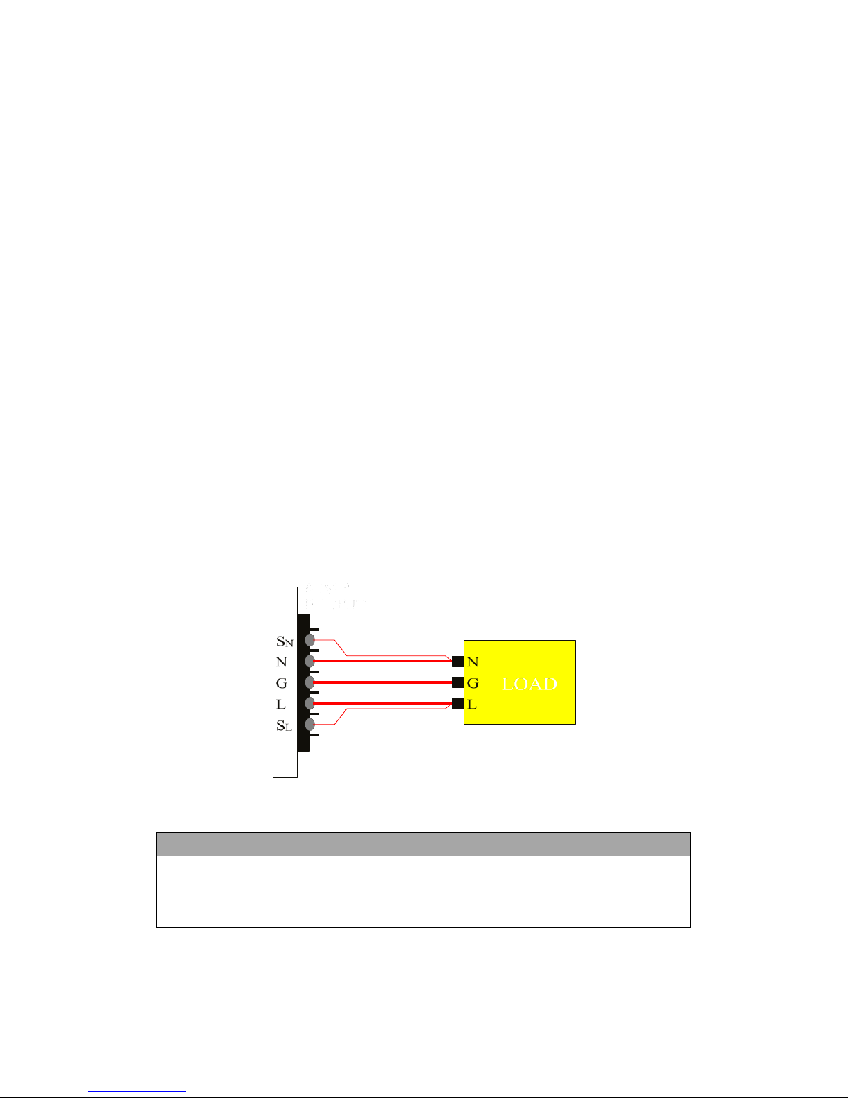
2.4 Output Connection
The output terminals are located on the rear panel of the product (see Figure 2.2).
The terminals “N” and “L” of the output terminals are connected to the load. To
match the safety requirements, the safety cover for the output terminals must be
fastened. The wires to the load must be sufficiently large gauges, so they will not
overheat while carrying the output current.
Figure 2.2 Output terminals
Figure 2.3 Output terminals to the load
NOTICE
When output voltage contains DC composition, Terminal “L” of the output ter-
minals indicates the “+” terminal; terminal “N” of the output terminals indi-
cates the “-” terminal.

AFV-P Series User Manual
11
2.5 Remote Sense Connection
The product supports remote sense function, which monitors the voltage at the load
instead of the output terminal of the product. It ensures the delivery of accurate
voltage as programmed at the load by automatically compensating the output voltage drop over the connecting cable.
Remove the iron chip from the terminals “SN” and “SL” of the remote sense connector,
and connect the terminals of the remote sense connector to the corresponding terminal of the load. Because the sensing leads carry only a few millamperes, the sensing leads are much lighter than the load leads. The sensing leads are part of the
feedback path of the product, so they must be kept at a low resistance in order to
maintain the best performance. The sensing leads must be connected to the load
carefully, so that they will not be open-circuited. If the sensing leads are left unconnected or become open-circuited during operation, the product will disable the output. The sensing leads must be a twisted pair to minimize the pickup of external
noise. The sensing leads need to be connected to the load as close as possible.
Figure 2.4 Remote sense connector

AFV-P Series User Manual
12
2.6 Power-on Procedures
WARNING
Before turning on the product, all protective grounding terminals, extension
cords, and devices connected to the product must be connected to a protective
ground. Any interruption of the protective ground will cause a potential shock
hazard that could result in personal injury.
Apply power and press the power switch to turn on the product, then the touch
screen located on the front panel will light up and display the POWER-ON page
shown as below,
Figure 2.5 POWER-ON page
After displaying the POWER-ON page, the MAIN page is continuously shown on the
touch screen as follows, and then users can input programming data or options by
either manipulating the touch screen or turning the rotary knob.
Figure 2.6 MAIN page
AFV-P Series User Manual
13
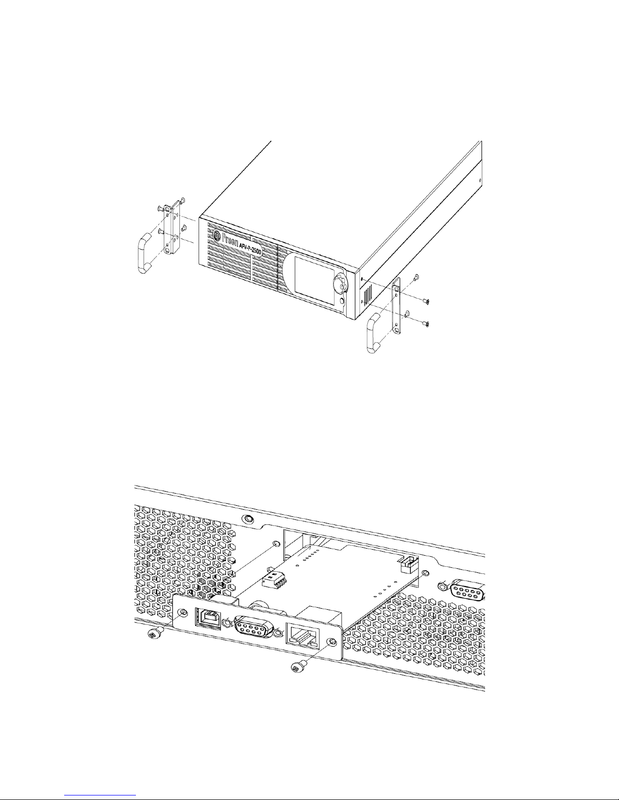
2.7 Product Handle Installation
To install the handles to the right-side and the left-side of the product, please refer to
the Figure 2.7 to fix the handles to the product with eight screws.
Figure 2.7 Product handle
2.8 Interface Card Installation
To install the interface card or replace the standard interface card with optional interface card, please refer to the Figure 2.8 to install or replace the interface card with
two screws.
Figure 2.8 Interface Card
AFV-P Series User Manual
14
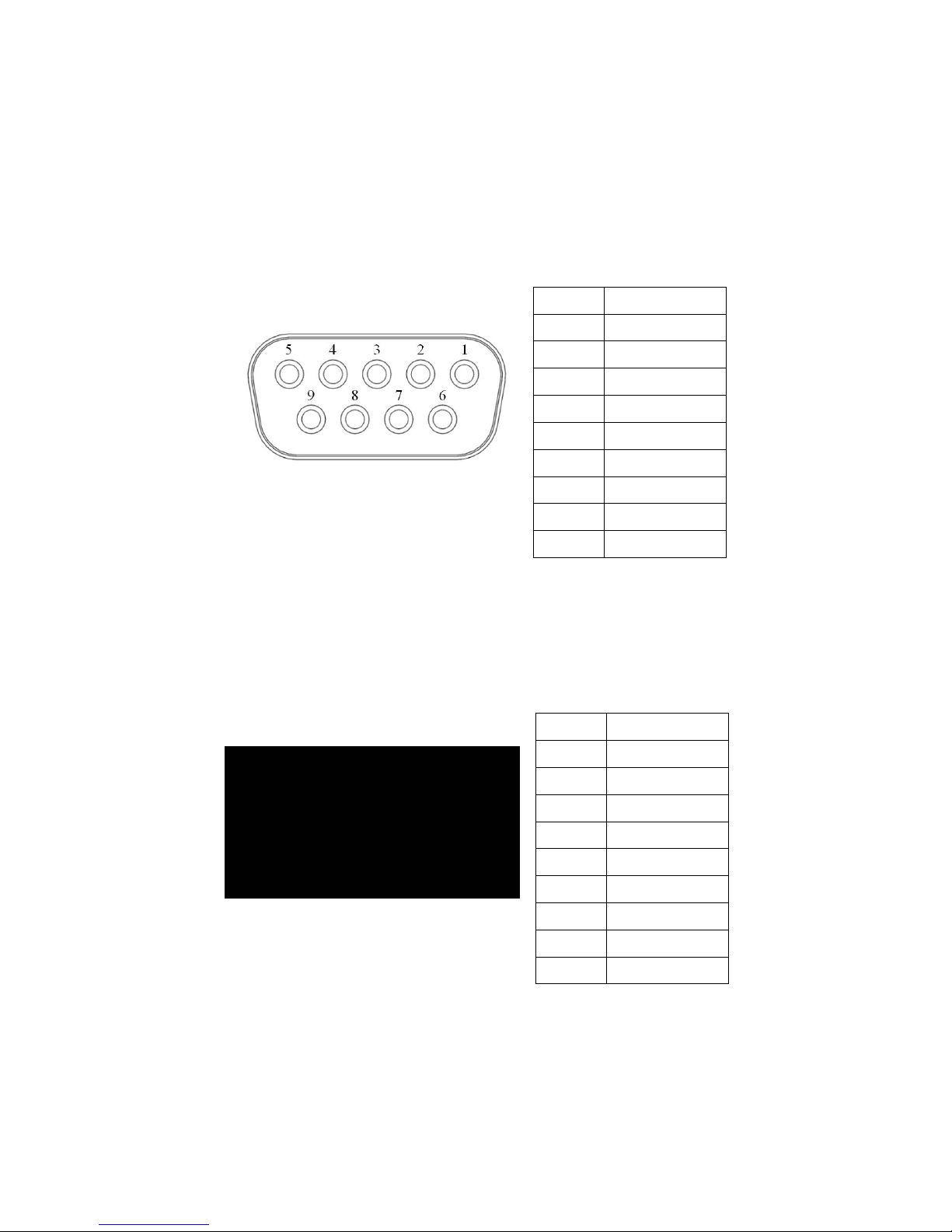
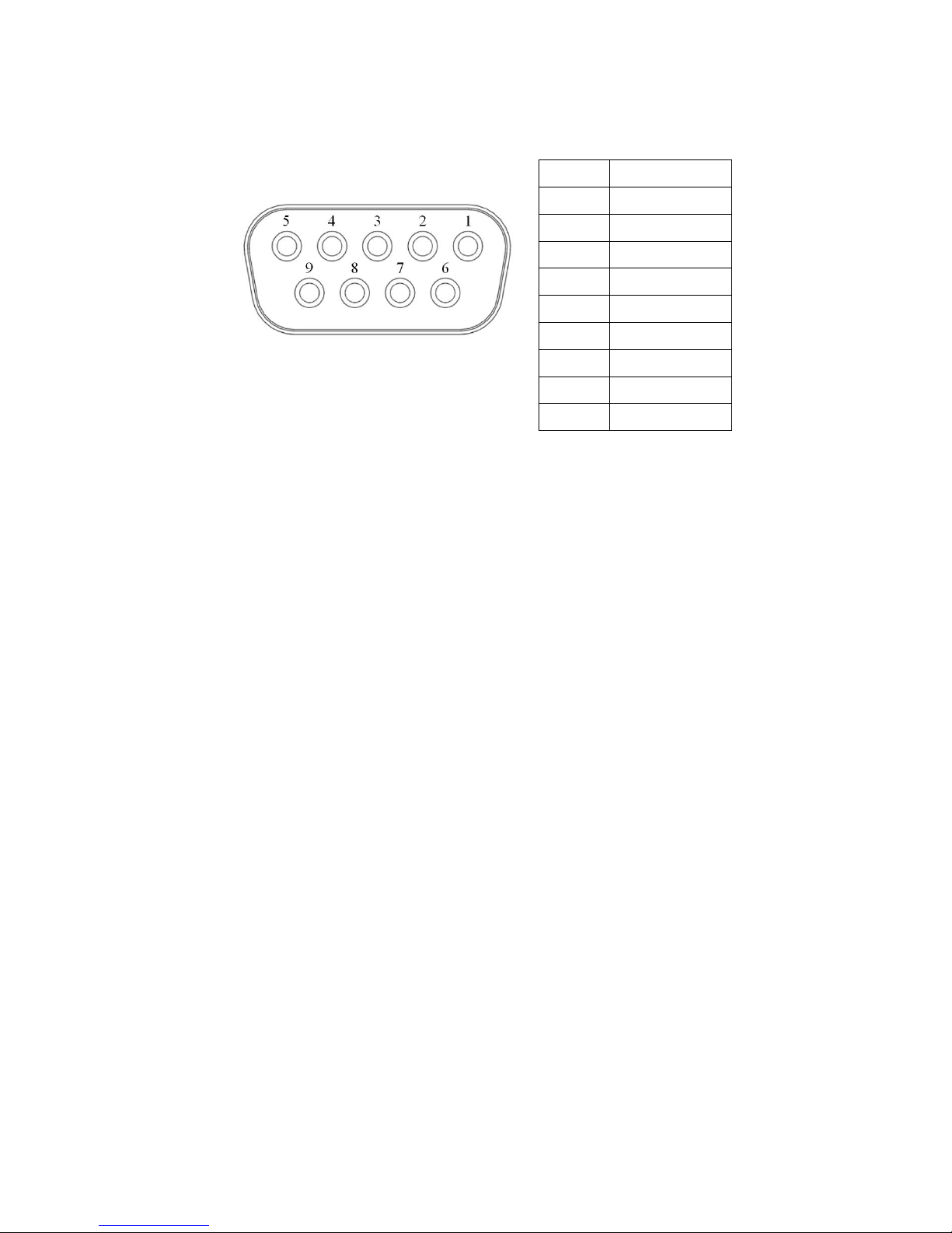
2.8.1 RS232/RS485 9-Pin D-Type Connector
To remotely control the product output via the interface RS232 or RS485, please
connect a computer with the product via the RS232/RS485 9-pin D-type connector
according to the following instructions.
The definition for the pins of the RS232/RS485 9-pin D-type female connector is given as follows:
Figure 2.9 RS232/RS485 9-Pin D-Type
female connector
Pin NO.
Definition
1
No Connection
2
RS232 TX
3
RS232 RX
4
No Connection
5
GND
6
No Connection
7
RS485 D+
8
RS485 D-
9
No Connection
2.8.2 PLC Remote In & Out Connector
To remotely control the product output via the PLC remote interface, please connect
a computer with the product via the PLC remote In & Out connector according to the
following instructions.
The definition for the pins of the PLC remote input male connector is given as follows,
Figure 2.10 PLC remote input male
connector
Pin NO.
Definition
1
No Connection
2
RS232 TX
3
RS232 RX
4
No Connection
5
GND
6
No Connection
7
RS485 D+
8
RS485 D-
9
No Connection
AFV-P Series User Manual
15
The definition for the pins of the PLC remote output female connector is given as
follows:
Figure 2.11 PLC remote output
female connector
Pin NO.
Definition
1
Pass
2
Pass
3
Fail 4 Fail
5
Processing
6
Processing
7
No Connection
8
No Connection
9
No Connection

AFV-P Series User Manual
16
3 Local Operation
3.1 General
The product can support local operation or remote operation. The remote operation
enabled via complete communication interfaces, such as RS232, RS485, Ethernet,
USB or GPIB will be described in Chapter 8. In this section, the local operation enabled via the touch screen and the rotary knob on the front panel will be described.
The product is configured for local operation when it is turned on.
3.2 Operation via the Touch Screen and the Rotary Knob
The product provides the user-friendly programming interface using the touch screen
and rotary knob on the front panel for users. Each display of the touch screen on the
product represents an operational page.
Before describing each operational page, the followings show how to use touch
screen and rotary knob to input programming data or options. When the power-on
procedures are finished (refer to Subsection 2.6), the touch screen will display the
MAIN page subsequently.
A. Touch Screen
Press the item shown on the touch screen directly, so as to choose the desired item
(see Figure 3.1). Use the virtual numeric and decimal keys to set value, and then
press the icon on the touch screen to confirm. After setting value, users can
revise value by pressing the icon , or press the icon to return to the
previous page.
Figure 3.1 Press the desired item on the touch screen

AFV-P Series User Manual
17
Figure 3.2 Virtual numeric and decimal keys
B. Rotary Knob
Turn the rotary knob on the front panel to move the cursor shown on the touch
screen, and press the rotary knob to choose the desired item. After choosing the desired item, continue to turn the rotary knob to set value, and then press the rotary
knob to confirm.
Figure 3.3 Move the cursor on the touch screen by turning the rotary knob

AFV-P Series User Manual
18
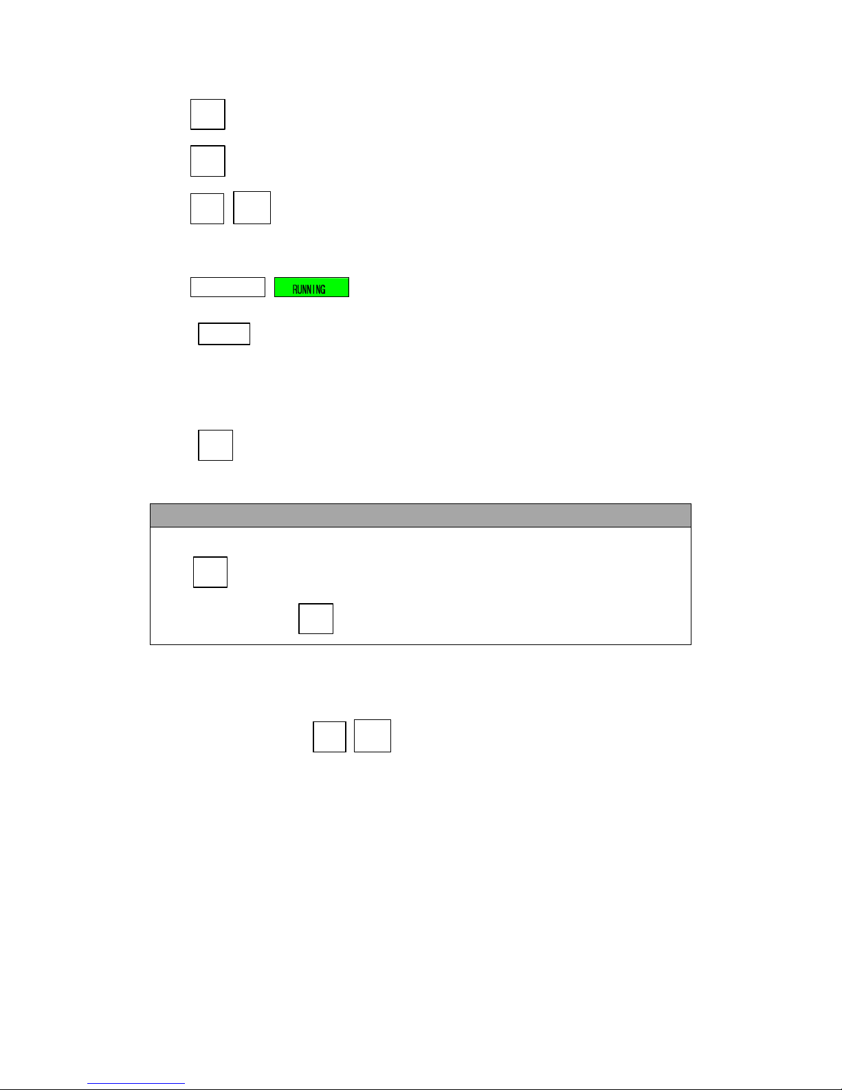
3.3 MAIN Page
When users turn on the product, the touch screen shows the MAIN page after the
power-on procedures. The MAIN page shows the output settings and the measurement readings of the product output. Users can set output value by using the touch
screen or the rotary knob (refer to Subsection 3.2), and then press the output & reset
button on the front panel to enable the output of the product. Please see the following figures:
Figure 3.4 MAIN page when the product output is off
Figure 3.5 MAIN page when the product output is on
The description for the items and the icons on the MAIN page are given as follows:
1) : Press to set the output voltage.
2) : Press to set the maximum rated current.
3) : Press to set the output frequency.
4) : Press to set the maximum rated power.
5) : Press to enter into the MENU page.
AFV-P Series User Manual
19
6) : Press to enter into the METER page.
7) : Press to enter into the PROGRAMMABLE page.
8) / : Press to set the output voltage range, with two options of HIGH
and AUTO.
9) / : Shown the status of the output or the error code.
10) : Press to lock/unlock the operation of the touch screen, and only
allow pages to switch between the MAIN page and the METER page when
the operation of the touch screen is locked.
11) : Press to enter into the WAVE page.
NOTICE
When the product output is off, the upper-right side of the MAIN page will be the
icon ; when the product output is on, the upper-right side of the MAIN
page will be the icon .
3.3.1 Output Voltage Range
The product supplies full output voltage range with two options of HIGH and AUTO.
Users can press the icon / to set output voltage range at the MAIN page.
HIGH indicates that the maximum output voltage will be 310V; AUTO indicates that
the maximum output voltage switches automatically between 155V and 310V as re-
quired.
AFV-P Series User Manual
20
Figure 3.6 Set the output voltage range from HIGH to AUTO
3.4 MENU Page
If the MAIN page is shown on the touch screen, users can press the icon to
enter into the MENU page. Please see the following figures,
Figure 3.7 MENU page 1 Figure 3.8 MENU page 2
The description for the icons at the MENU page is given as follows:
1) : Press to enter into the SETTINGS page.
2) : Press to enter into the PROGRAMMABLE page.
3) : Press to enter into the COMMUNICATION page.
4) : Press to enter into the RESULTS page.
5) : Press to enter into the WAVE page.
AFV-P Series User Manual
21
6) : Press to enter into the METER page.
7) : Press to enter into the INFORMATION page.
8) : Press to return to the MAIN page.
9) : Press to return to the previous page.
10) : Press to move to the previous page of the MENU page.
11) : Press to move to the next page of the MENU page.
3.5 SETTINGS Page
If the MENU page is shown on the touch screen, users can press the icon to
enter into the SETTINGS page, and the SETTINGS page includes two subpages: the
TESTING subpage and the SYSTEM subpage.
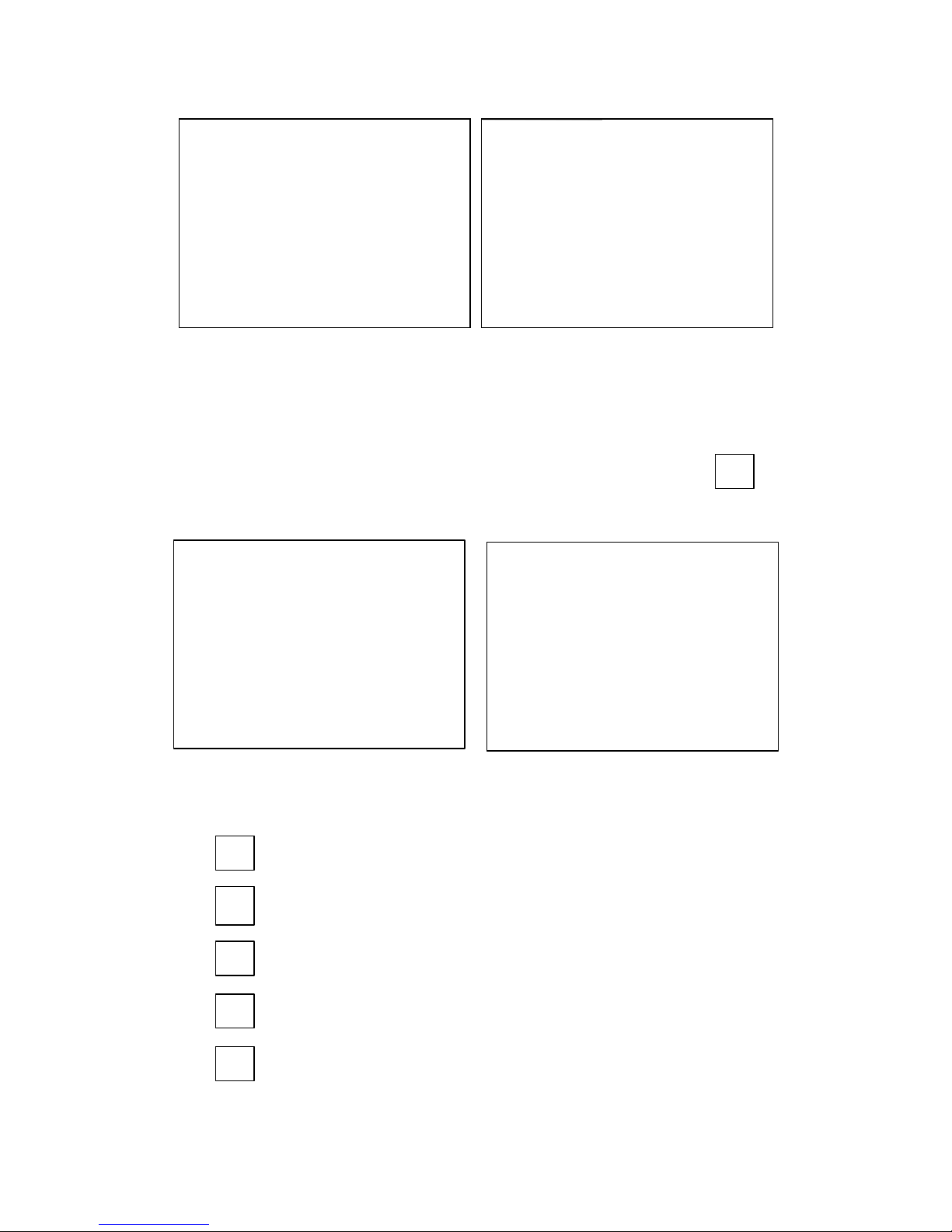
3.5.1 TESTING Subpage (ADVANCED Mode)
After pressing the icon to enter into the SETTINGS page, the TESTING sub-
page at the ADVANCED mode will be shown on the touch screen in advance, and the
ADVANCED mode is the default operational mode. Please see the following figures:
Figure 3.9 TESTING subpages 1 & 2 (ADVANCED mode)

AFV-P Series User Manual
22
Figure 3.10 TESTING subpage 3 & 4 (ADVANCED mode)
The description for the items and the icons at the TESTING subpage (ADVANCED
mode) are given as follows:
1) : Press to set the operational mode, with two options
of ADVANCE and BASIC.
2) : Press to set the output mode, with two options of
AC and DC.
3) : Press to enable/disable the over current foldback,
with two options of OFF and ON.
4) : Press to set the start angle, with options from 0 to
359.
5) : Press to set the end angle, with options from 0 to
359.
6) : Press to set the power-on status, with three options
of OFF, ON and LAST.
7) : Press to set the voltmeter point, with two options of
INT and EXT.
8) : Press to enable/disable the fail stop feature, with
two options of OFF and ON.

AFV-P Series User Manual
23
9) : Press to enable/disable the consecutive step feature,
with two options of ON and OFF.
10) : Press to enable/disable the synchronized signal,
with three options of EVENT, OFF and ON.
11) : Press to move to the previous page of the TESTING subpage.
12) : Press to move to the next page of the TESTING subpage.
NOTICE
The present operational mode can be seen on the lower-left side of the touch
screen (that is, the icon / ). Users can set the operational
mode from the default ADVANCED mode to the BASIC mode by pressing the icon
twice at the TESTING subpage 1 on the touch screen. The
detailed description of the BASIC mode will be given in Section 3.5.2.

AFV-P Series User Manual
24
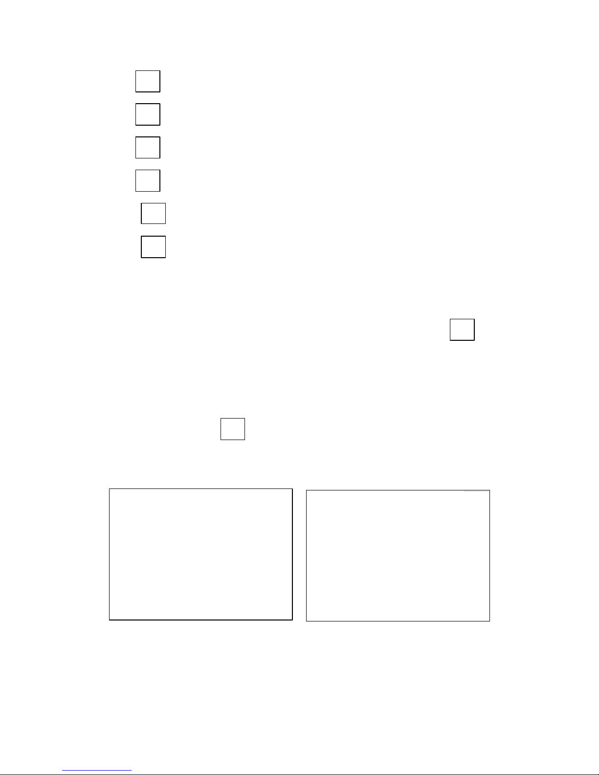
3.5.1.1 Output Mode (AC or DC)
At the TESTING subpage 1 (ADVANCED mode), users are allowed to set the output
mode with two options of AC and DC, so as to fit their application. Then, the MAIN
page will change correspondingly according to the output mode.
Figure 3.11 MAIN page when the output mode is AC
Figure 3.12 MAIN page when the output mode is DC
The procedures of setting the output mode from AC to DC are given as below:
1. Press the item twice to set the output mode from AC
to DC.
2. Press the icon to confirm.
 Loading...