

Preen ADG-P-40-750, ADG-P-100-300, ADG-P-60-500, ADG-P-200-150, ADG-P-240-125 User Manual
...
ADG-P Series
Programmable DC Power Supply
User Manual
AC Power Corp. (Preen)
V 1.02.00EN
The information in this document is subject to change without notice.
©AC Power Corp. (Preen). All rights reserved

Contents
Legal Notices
The information in this product manual is subject to change without notice.
AC Power Corp. makes no warranty of any kind with regard to this user manual, including, but not limited to, the implied warranties of merchantability and fitness for
a particular purpose. AC Power Corp. shall not be held liable for errors contained
herein or direct, indirect, special, incidental or consequential damages in connection
with the furnishing, performance, or use of this material.
Copyright Notices. Copyright 2017 AC Power Corp. (Preen), all rights reserved. Reproduction, adaptation, or translation of this document without prior written permission is prohibited, except as allowed under the copyright laws.

Contents
Warranty
Preen’s ADG-P series is warranted against defects in material and workmanship for a
period of two year after date of shipment. Preen agrees to repair or replace any assembly or component found to be defective, under normal use during this period.
Preen’s obligation under this warranty is limited solely to repairing any such product
which in sole Preen’s opinion proves to be defective within the scope of the warranty when returned to the factory or to an authorized service center. Transportation to
the factory or service center is to be prepaid by the purchaser. Shipment should not
be made without prior authorization by Preen.
This warranty does not apply to any products repaired or altered by persons not authorized by Preen, or not in accordance with instructions furnished by Preen. If the
product is defective as a result of misuse, improper repair, or abnormal conditions or
operations, repairs will be billed at cost.
Preen assumes no responsibility for its product being used in a hazardous or dangerous manner either alone or in conjunction with other equipment. High voltage
used in some products may be dangerous if misused. Special disclaimers apply to
these products. Preen assumes no liability for secondary charges or consequential
damages and in any event, Preen’s liability for breach of warranty under any contract or otherwise, shall not exceed the purchase price of the specific product
shipped and against which a claim is made.
Any recommendations made by Preen for use of its products are based upon tests
believed to be reliable, but Preen makes no warranty of the results to be obtained.
This warranty is in lieu of all other warranties, expressed or implied, and no representative or person is authorized to represent or assume for Preen any liability in
connection with the sale of our products other than set forth herein.
AC Power Corp. (Preen)
USA
192 Technology Dr., Suite S, Irvine, CA 92618
TEL +1 949-988-7799
Taipei
3F No. 200 Gangqian Road, Neihu Dist., Taipei 114, Taiwan
TEL +886 2-2627-1899 FAX +886 2-2627-1879

Contents
SAFETY SUMMARY
The following general safety precautions must be observed during all phases of operation, service, and repair of this product. Failure to comply with these precautions
or specific WARNINGS given elsewhere in this manual will violate safety standards of
design, manufacture, and intended use of the product.
Preen assumes no liability for the customer‘s failure to comply with these requirements.
BEFORE APPLYING POWER
Verify that the product is set to match with the power line input.
PROTECTIVE GROUNDING
Make sure to connect the product to the protective ground to prevent an electric
shock before turning on the power.
NECESSITY OF PROTECTIVE GROUNDING
Never cut off the internal or external protective grounding wire, or disconnect the
wiring of protective grounding terminal. Doing so will cause a potential shock hazard
that may bring injury to a person.
DO NOT OPERATE IN AN EXPLOSIVE ATMOSPHERE
Do not operate the product in the presence of flammable gases or fumes.
DO NOT REMOVE THE COVER OF THE PRODUCT
Personnel who operate the product must not remove the cover of the product.
Component replacement and internal adjustment can be done only by qualified service personnel.
WARNING
LETHAL VOLTAGES. DEATH on contact may result if either the output terminals or
the output circuits connected to the output are touched when the product output
is on.

Contents
Table of Contents
1 GENERAL INFORMATION ............................................................................................... 1
1.1 Introduction .................................................................................................... 1
1.2 Specifications .................................................................................................. 1
1.3 Exterior ........................................................................................................... 6
2 INSTALLATION .................................................................................................................. 9
2.1 Inspection ....................................................................................................... 9
2.2 User Preparation ............................................................................................. 9
2.3 Remove the Front Door from the Product Enclosure ....................................... 10
2.4 Input Connection ............................................................................................ 10
2.5 Output Connection ......................................................................................... 11
3 LOCAL OPERATION ....................................................................................................... 13
3.1 Power-on Procedures ..................................................................................... 13
3.2 General Page .................................................................................................. 14
3.2.1 Output Measurement ................................................................................................. 15
3.2.2 Output Settings ........................................................................................................... 15
3.2.3 Run & Stop .................................................................................................................. 15
3.2.4 Constant Voltage Mode .............................................................................................. 15
3.2.5 Constant Current Mode .............................................................................................. 16
3.3 Function Page ................................................................................................. 17
3.3.1 Step Setting ................................................................................................................. 17
3.3.2 Step Performing .......................................................................................................... 18
3.3.3 Gradual Setting ........................................................................................................... 19
3.3.4 Gradual Performing .................................................................................................... 20
3.4 Protection ...................................................................................................... 21
3.4.1 Protection: Vin UVP .................................................................................................... 21
3.4.2 Protection: Vin OVP .................................................................................................... 21
3.4.3 Protection: OVP .......................................................................................................... 22
3.4.4 Protection: OCP .......................................................................................................... 22
4 REPAIR AND MAINTENANCE ..................................................................................... 23

Contents
4.1 Emergency Troubleshooting ........................................................................... 23
4.2 Dust Check ..................................................................................................... 23
4.3 Product Maintenance ..................................................................................... 23
4.3.1 Daily Maintenance ...................................................................................................... 23
4.3.2 Monthly Maintenance ................................................................................................ 25
5 REMOTE CONTROL ....................................................................................................... 26
5.1 Remote Read .................................................................................................. 26
5.2 Remote Write ................................................................................................. 27
5.3 Transmission Example .................................................................................... 28
5.4 MODBUS Address Table .................................................................................. 31

ADG-P Series User Manual
1
1 General Information
1.1 Introduction
Preen’s ADG-P series is a programmable DC power supply with high power density
and high output power, and it offers great response time, high accuracy and many
output voltage and current combinations. Designed for the increasing demand of
high power DC power supplies, ADG-P series is ideal for testing EV-type motor/compressor, server power supply, fuse, circuit breaker, contactor and PV inverter,
or ADG-P series can be used as a facility power or EMC chamber power.
With output power up to 100kW per unit, ADG-P series can offer output voltage up
to 1600V or output current up to 2000A. Users can select standard interface RS-485
or optional interfaces RS-232 and GPIB. With built-in STEP and GRADUAL features,
ADG-P series allows easy setup on test sequence. According to CV/CC settings and
load conditions, ADG-P series can operate as a current or voltage source. Its remote
sense feature can effectively reduce voltage drop caused by cable length and provides more flexibility on installation.
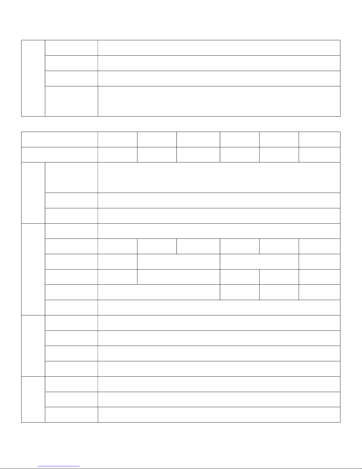
1.2 Specifications
Technical specifications of product are listed below. All specifications have been
tested according to Preen’s standard test procedures.
30kW ADG-P-40-750 ADG-P-60-500 ADG-P-100-300 ADG-P-200-150 ADG-P-240-125 ADG-P-320-94
50kW ADG-P-40-1250 ADG-P-60-834 ADG-P-100-500 ADG-P-200-250 ADG-P-240-208 ADG-P-320-156
AC
Input
Voltage
3Φ3W + G
380 VAC/400VAC/415VAC/440VAC/480VAC ± 10%
Frequency 47-63Hz
Power Factor
≧90% at maximum power
DC
Output
Line Regulation
≦0.3% ≦0.1%
Load Regulation
≦0.3% ≦0.065% ≦0.104% ≦0.14%
Voltage Ripple (RMS)
≦0.5% ≦0.26% ≦0.19% ≦0.16%

ADG-P Series User Manual
2
Voltage Noise (Peak)
≦3.7% ≦2% ≦0.88%
Voltage Slew Rate*1
≦65ms ≦60ms ≦85ms
Transient Response*2
≦4-12ms
Measurement
Voltage Accuracy 0.5% F.S.
Voltage Resolution 0.1V
Current Accuracy 0.5% F.S.
Current Resolution 0.1A
Protection
Type Vin OVP, Vin UVP, OVP, OCP and OTP
OVP Range 5% - 115% from front panel
OVP Accuracy 1% F.S.
OCP Range 5% - 115% from front panel
OCP Accuracy 1% F.S.
General
Efficiency
≧87% ≧90%
Remote Sense Limits
3% maximum voltage drop from product output to load
(for product models with output voltage lower than 1000VDC)
Operational Temperature
0°C-40°C
Storage Temperature -20°C-70°C
Isolation Input to product cover: 2000VAC
Dimension (H×W×D) 41.5×23.6×31.5 inch3/1050×600×800 mm3
Weight*3
30kW: approx. 496lbs/225kg
50kW: approx. 511lbs/232kg
30kW: approx. 412lbs/187kg
50kW: approx. 423lbs/192kg

ADG-P Series User Manual
3
30kW ADG-P-400-75 ADG-P-500-60 ADG-P-640-47 ADG-P-800-38 ADG-P-1000-30 ADG-P-1600-18
50kW ADG-P-400-125 ADG-P-500-100 ADG-P-640-78 ADG-P-800-63 ADG-P-1000-50 ADG-P-1600-31
AC
Input
Voltage
3Φ3W + G
380 VAC/400VAC/415VAC/440VAC/480VAC ± 10%
Frequency 47-63Hz
Power Factor
≧90% at maximum power
DC
Output
Line Regulation
≦0.1%
Load Regulation
≦0.032% ≦0.14% ≦0.132% ≦0.034% ≦0.02% ≦0.05%
Voltage Ripple (RMS)
≦0.13% ≦0.109% ≦0.07% ≦0.05% ≦0.08%
Voltage Noise (Peak)
≦0.88% ≦1.34% ≦0.77% ≦0.29% ≦0.27% ≦0.4%
Voltage Slew Rate*1
≦115ms ≦280ms
Transient Response*2
≦4-12ms
Measurement
Voltage Accuracy 0.5% F.S.
Voltage Resolution 0.1V
Current Accuracy 0.5% F.S.
Current Resolution 0.1A
Protection
Type Vin OVP, Vin UVP, OVP, OCP and OTP
OVP Range 5% - 115% from front panel
OVP Accuracy 1% F.S.
OCP Range 5% - 115% from front panel
OCP Accuracy 1% F.S.
General
Efficiency
≧90%
Remote Sense Limits
3% maximum voltage drop from product output to load
(for product models with output voltage lower than 1000VDC)
Operational Temperature
0°C-40°C
ADG-P Series User Manual
4
Storage Temperature -20°C-70°C
Isolation Input to product cover: 2000VAC
Dimension (H×W×D) 41.5×23.6×31.5 inch3/1050×600×800 mm3
Weight*3
30kW: approx. 412lbs/187kg
50kW: approx. 423lbs/192kg
75kW ADG-P-40-1875 ADG-P-60-1250 ADG-P-100-750 ADG-P-320-234 ADG-P-640-117 ADG-P-1000-75
100kW ADG-P-40-2500 ADG-P-60-1666 ADG-P-100-1000 ADG-P-320-313 ADG-P-640-156 ADG-P-1000-100
AC
Input
Voltage
3Φ3W + G
380 VAC/400VAC/415VAC/440VAC/480VAC ± 10%
Frequency 47-63Hz
Power Factor
≧90% at maximum power
DC
Output
Line Regulation
≦0.1%
Load Regulation
≦0.1% ≦0.15% ≦0.15% ≦0.08% ≦0.08% ≦0.1%
Voltage Ripple (RMS)
≦1.3% ≦1.5% ≦0.1% ≦0.2%
Voltage Noise (Peak)
≦7% ≦5% ≦0.65% ≦0.35% ≦0.8%
Voltage Slew Rate*1
≦120ms ≦90ms ≦120ms ≦130ms
Transient Response*2
≦10-20ms
Measurement
Voltage Accuracy 0.5% F.S.
Voltage Resolution 0.1V
Current Accuracy 0.5% F.S.
Current Resolution 0.1A
Protection
Type Vin OVP, Vin UVP, OVP, OCP and OTP
OVP Range 5% - 115% from front panel
OVP Accuracy 1% F.S.

ADG-P Series User Manual
5
OCP Range 5% - 115% from front panel
OCP Accuracy 1% F.S.
General
Efficiency
≧90%
Remote Sense Limits
3% maximum voltage drop from product output to load
(for product models with output voltage lower than 1000VDC)
Operational Temperature
0°C-40°C
Storage Temperature -20°C-70°C
Isolation Input to product cover: 2000VAC
Dimension (H×W×D) 59.8×23.6×31.5 inch3/1520×600×800 mm3
Weight*3
≦300kg
*1 For output voltage change from 5% to 90% at maximum power after output softstart.
*2 Recover to ±0.1% of regulated output with a 50% to 100% or 100% to 50% step load change.
*3 Weight might be different due to optional features or different input voltage. Please contact us for details.
All specifications are subject to change without notice.
Above specification is for output voltage over 1%.
Table 1.1 Technical specifications
ADG-P Series User Manual
6
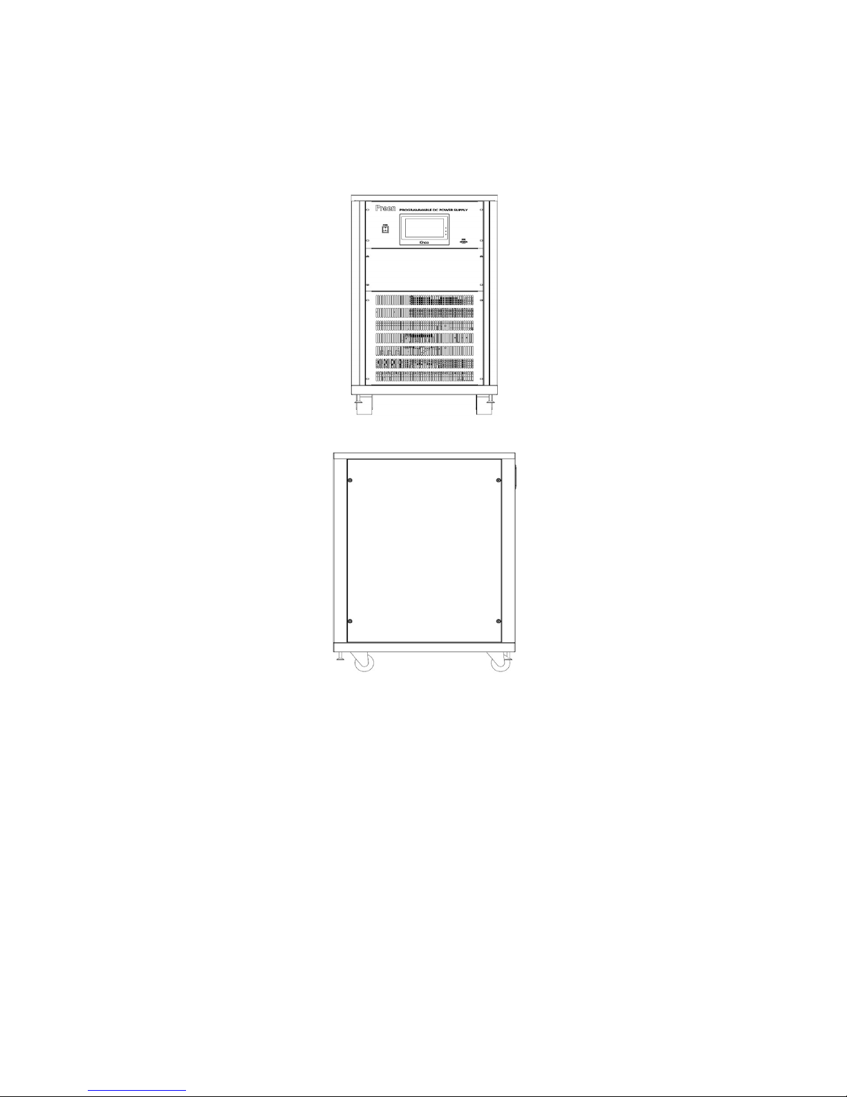
1.3 Exterior
Product exterior of the ADG-P series with power level 30kW, 50kW, 75kW and 100kW
are given as follows,
(a) Front-side view of the ADG-P series (30kW&50kW)
(b) Right-side view of the ADG-P series (30kW&50kW)
Figure 1.1 Product exterior of the ADG-P series (30kW&50kW)

ADG-P Series User Manual
7
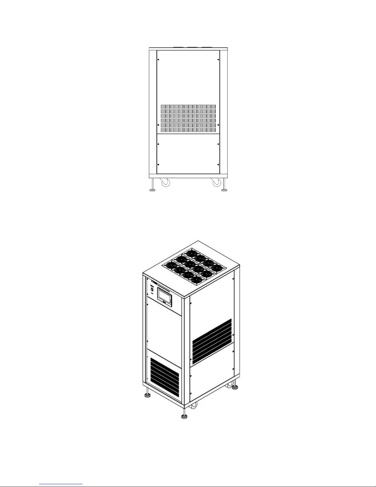
Figure 1.2 Product exterior of the ADG-P series in axis-side view (30kW&50kW)
(a) Front-side view of the ADG-P series (75kW&100kW)
ADG-P Series User Manual
8
(b) Right-side view of the ADG-P series (75kW&100kW)
Figure 1.3 Product exterior of the ADG-P series (75kW&100kW)
Figure 1.4 Product exterior of the ADG-P series in axis-side view (75kW&100kW)

ADG-P Series User Manual
9
2 Installation
2.1 Inspection
Each ADG-P series DC power supply has been carefully tested by Preen before shipping, but some damage might occur on the product during shipping, so please inspect the product carefully before installation. If there is any damage, please contact
the shipping company or directly contact Preen, and provide photos according to the
damage. A technical staff will contact users immediately.
2.2 User Preparation
ADG-P series should be installed in indoor and in dry environment with little dust.
Location for installing ADG-P series must be stable and secure due to its heavy
weight, and users should notice that ADG-P series is better to be placed on the
ground.
The front space for the product should be space with at least 105 cm length in order
to fully remove the front door. For easy maintenance and well ventilated, the back
space for the product should be space with at least 80 cm length, and its top space
should be space with at least 60 cm length.
Make sure that the ambient temperature around the product should be lower than
40˚C.

ADG-P Series User Manual
10
2.3 Remove the Front Door from the Product Enclosure
For input/output connection, please remove the front door from the product enclosure since the front door is fixed to the product via screws, and there are terminals
of AC input and DC output inside the front door.
Figure 2.1 Remove the front door from the product enclosure
2.4 Input Connection
The AC input terminals are located inside the front door of the product (see Figure
2.2). AC wires must be rated at least for 85C. The AC wires must have rated current
which complies with Spec. limit of the product.
To perform input connection for the product, please see Figure 2.2 and do the following procedures step by step:
1. Use a multi-meter to confirm that power line input complies with the Spec.
limit of the product.
2. Stop the power line input, and use the multi-meter to confirm that input voltage (L-L) from the power line input should be 0.
3. Connect the AC input terminals of L1, L2 and L3 with the power line input of L1,
L2 and L3 via AC wires sequentially.

ADG-P Series User Manual
11
4. Confirm that the AC wires between the power line input and the AC input terminals are secured.
Installation of the AC wires to the product must be done by a professional and according to local electrical codes.
Figure 2.2 AC Input terminals
2.5 Output Connection
To perform output connection for the product, please see Figure 2.3 and do the following procedures step by step:
1. Stop the product output, and use the multi-meter to confirm that output voltage should be 0.
2. Connect the DC output terminals “+” and “-” with positive and negative terminals from the load via metal wires sequentially.
3. Confirm that metal wires between the DC output terminals and the load are
secured.
AC Input Terminals

ADG-P Series User Manual
12
Figure 2.3 DC output terminals
DC Output Terminals

ADG-P Series User Manual
13
3 Local Operation
3.1 Power-on Procedures
WARNING
Before turning on the product, all protective grounding terminals, extension
cords, and devices connected to the product must be connected to a protective
ground. Any interruption of the protective ground will cause a potential shock
hazard that could result in personal injury.
After applying power and turning on the product, the touch screen located on the
front panel will light up and display the start-up page shown as below, and then it
will enter into General page in few seconds.
Figure 3.1 Start-up page

ADG-P Series User Manual
14
3.2 General Page
The description for the items and the icons at the General page are given according
to the figure below. Users can press the display area, and then the digital scope will
be shown at the General page to provide product output waveform.
Figure 3.2 General page
Figure 3.3 Digital scope at the General page
NOTICE
Before pressing the icon “RUN” at the General page to start the product output,
make sure that output terminals are correctly connected to the load.

ADG-P Series User Manual
15
3.2.1 Output Measurement
At the General page, the item “Voltage” indicates measurement of the present DC
output voltage; the item “Current” indicates measurement of the present DC output
current; the item “Power” indicates measurement of the DC output power.
3.2.2 Output Settings
At the General page, the item “V-set” indicates the DC output voltage set; the item
“I-set” indicates the DC output current set; the item “Setting” indicates function of
time setting; the icon “Reset” indicates function of product reset after protection.
3.2.3 Run & Stop
The product will start the DC output after pressing the icon “Run” at the General
page. Similarly, the product will stop the DC output after pressing the icon “Stop” at
the General page.
3.2.4 Constant Voltage Mode
When the output current from the load is lower than or equal to the DC output current set, the product will perform at the constant voltage mode. Once the product
performs at the constant voltage mode, the sign will be shown next to the
item “Voltage” at the General page.
Figure 3.4 General page when the product performs at the constant Voltage mode

ADG-P Series User Manual
16
3.2.5 Constant Current Mode
When the output current from the load is higher than the DC output current set, the
product will perform at the constant current mode. Once the product performs at
the constant current mode, the sign will be shown next to the item “Current” at the General page.
Figure 3.5 General page when the product performs at the constant Voltage mode
NOTICE
When ADG-P series performs at the constant current mode, the DC output voltage
will be automatically adjusted to match load conditions.
ADG-P Series User Manual
17
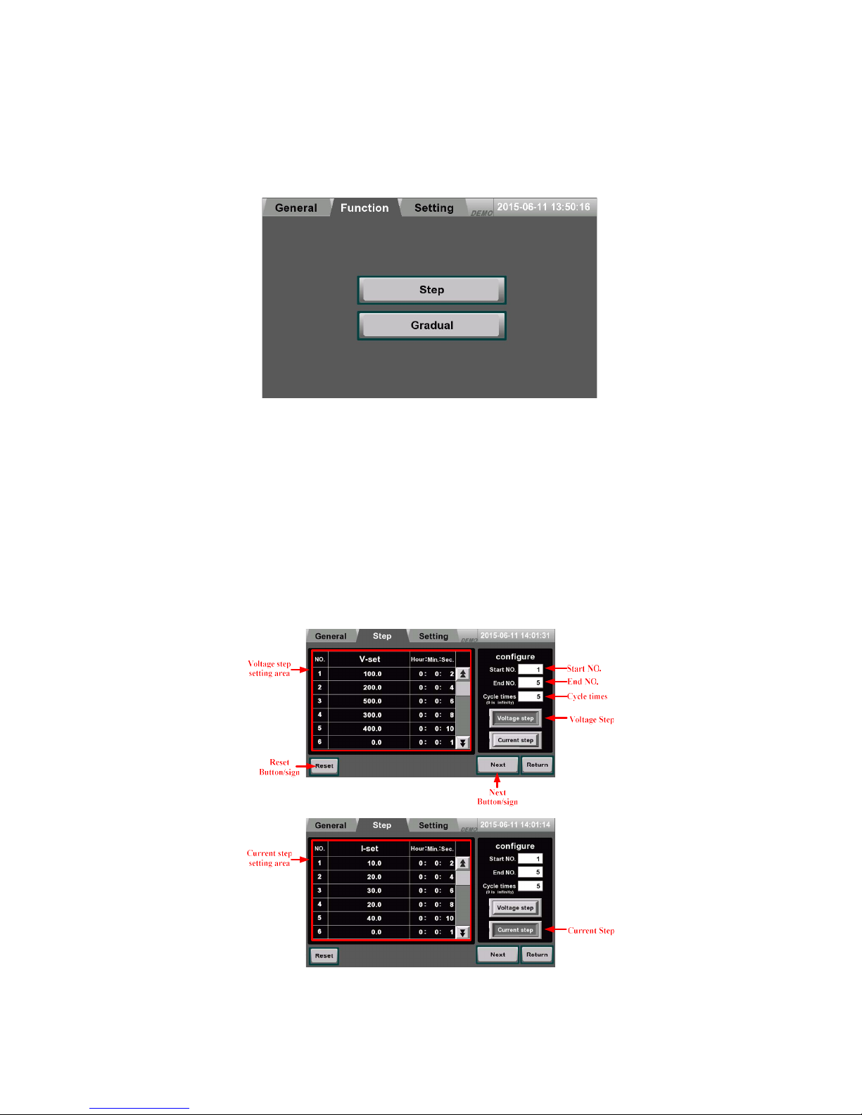
3.3 Function Page
Press the icon “Function” to enter into the function page.
Figure 3.6 Function page
3.3.1 Step Setting
Press the icon “Step” to enter into the step page, and the step page is shown below.
After entering into the step page, press the icon “Voltage step” or “Current step” to
operate at voltage/current step mode. Then, set output voltage/current and dwell
time for each set (up to 24 sets) in the step setting area, and set start number, end
number and cycle times for performing the step feature (repeatedly performing the
step feature when setting the cycle times as 0). After finishing the setting above,
press the icon “Next” to enter into the next page.
Figure 3.7 Step setting

ADG-P Series User Manual
18
3.3.2 Step Performing
Press the icon “Run” to perform the step feature, and output status is shown on the
output display area. Similarly, the output display area can show the output status by
waveform display or digit display. “Run status” includes performing number, output
voltage, elapsed time and total cycle times. Press the icon “Lock” to lock the function
of other icons. Press the icon “Stop” to stop the step feature. Once an abnormal condition occurs, press the icon “Reset” to eliminate the abnormal condition, and press
the icon “Return” to return to the step page.
Figure 3.8 Step performing

ADG-P Series User Manual
19
3.3.3 Gradual Setting
Press the icon “Gradual” to enter into the gradual page, and the gradual page is
shown below. After entering into the gradual page, press the icon “Voltage grad” or
“Current grad” to operate at voltage/current gradual mode. Then, set start output
voltage/current, end output voltage/current and dwell time for each set (up to 12
sets) in the gradual setting area, and set start number, end number and cycle times
for performing the step feature (repeatedly performing the gradual feature when
setting the cycle times as 0). After finishing the setting above, press the icon “Next”
to enter into the next page.
Figure 3.9 Gradual setting
ADG-P Series User Manual
20
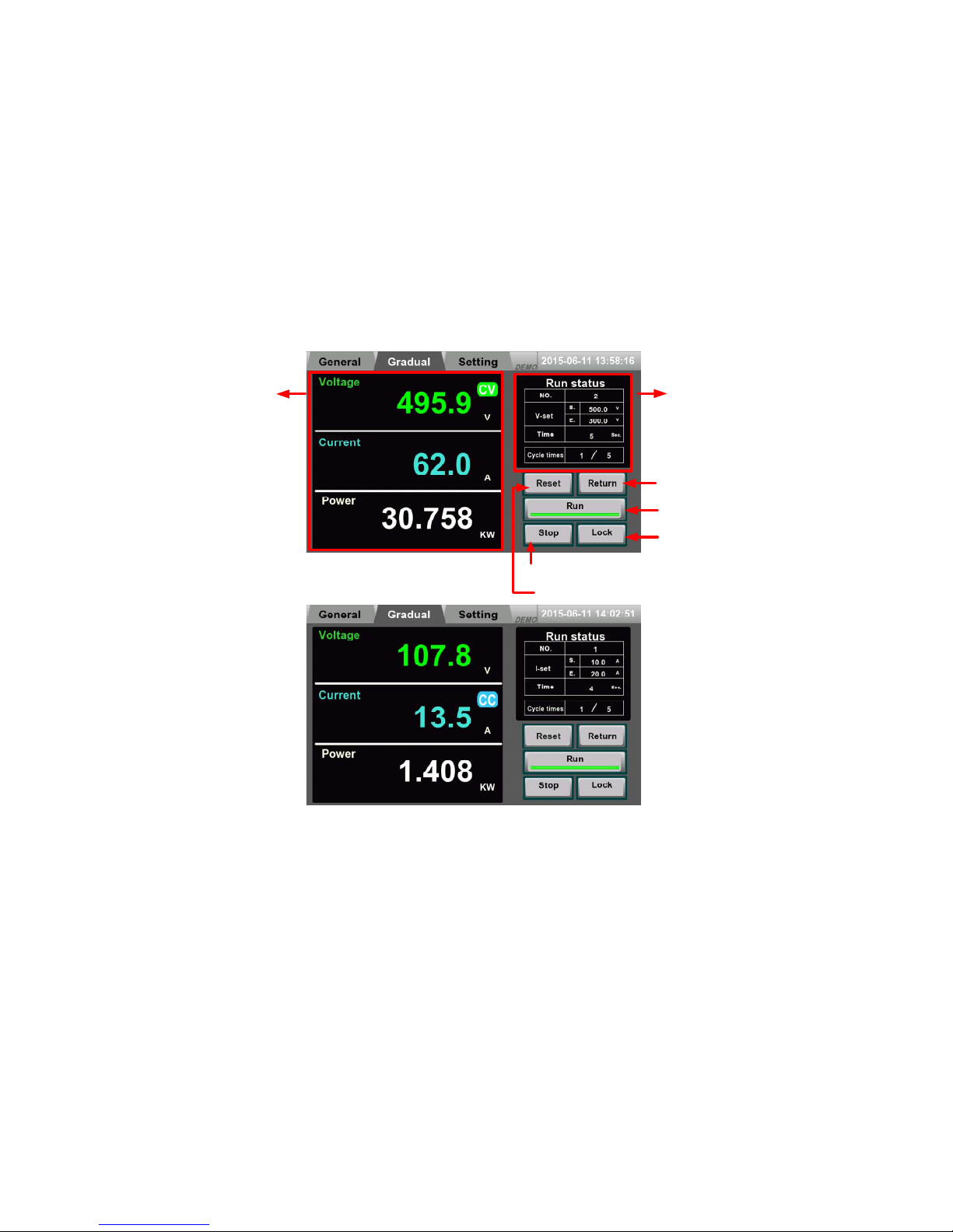
3.3.4 Gradual Performing
Press the icon “Run” to perform the gradual feature, and output status is shown on
the output display area. Similarly, the output display area can show the output status
by waveform display or digit display. “Run status” includes performing number, output voltage, elapsed time and total cycle times. Press the icon “Lock” to lock the
function of other icons. Press the icon “Stop” to stop the gradual feature. Once an
abnormal condition occurs, press the icon “Reset” to eliminate the abnormal condition, and press the icon “Return” to return to the gradual page.
Run status
Lock
Button/sign
Return
Button/sign
Output
Button/sign
Close
Button/sign
Reset
Button/sign
Output
display
area
Figure 3.10 Gradual performing

ADG-P Series User Manual
21
3.4 Protection
3.4.1 Protection: Vin UVP
When the input voltage for the product is lower than a default value, Vin UVP will be
triggered and the product will immediately stop the output. Then, the sign “Vin UV”
will be shown below the item “Voltage” at the General page. To reset the product
from Vin UVP, please press the icon “Reset”.
3.4.2 Protection: Vin OVP
When the input voltage for the product is higher than a default value, Vin OVP will be
triggered and the product will immediately stop the output. Then, the sign “Vin OV”
will be shown below the item “Voltage” at the General page. To reset the product
from Vin OVP, please press the icon “Reset”.

ADG-P Series User Manual
22
3.4.3 Protection: OVP
When the output voltage of the product is higher than a default value, OVP will be
triggered and the product will immediately stop the output. Then, the sign “OV” will
be shown below the item “Voltage” at the General page. To reset the product from
OVP, please press the icon “Reset”.
3.4.4 Protection: OCP
When the output current of the product is higher than the DC output current set,
OCP will be triggered and the product will immediately stop the output. Then, the
sign “OC” will be shown below the item “Current” at the General page. To reset the
product from OCP, please press the icon “Reset”.

ADG-P Series User Manual
23
4 Repair and Maintenance
4.1 Emergency Troubleshooting
If ADG-P series has any abnormal conditions or triggers any product protection, users
must immediately stop the product output and turn off the product.
4.2 Dust Check
ADG-P series must be installed in dry and clean room, and please clean the dust for
the product every six months once.
4.3 Product Maintenance
Extreme temperature, high humidity, heavy dust, chemical pollution and physical vibration all could impose negative impacts on the life and reliability of the product.
However, the natural aging of all the electrical and mechanical components would
further cause it to be more vulnerable to all kinds of faults. Therefore, daily and
monthly maintenance are necessary, and they are important to the reliability of the
product in the long run.
NOTICE
Only authorized and trained technical staffs are allowed to carry out the maintenance on the product.
4.3.1 Daily Maintenance
First, this product must operate in the environment stated in this user manual. Daily
inspection on the environment and this product should be carried out regularly. It is
recommended to record product data of operational environment, operational condition, output settings and etc. For product maintenance and its reference, it is also
recommended to build detailed “product usage log file”.

ADG-P Series User Manual
24
Abnormal conditions on the product can be detected by the daily inspection and
maintenance. Once an abnormal condition is detected, users should identify its root
cause, and eliminate the abnormal condition accordingly. If users are unable to identify the root cause or eliminate the abnormal condition, please call our customer service for technical support immediately. The earlier the abnormal condition can be
removed, the longer the life of the product. Please check the daily maintenance list
given below,
Object
Details
Criteria
Items Period
Methods
Environment
1. Temperature and humidity
2. Dust, moisture and water
leakage
3. Abnormal chemical vapor
Anytime
1. Thermometer and hygrometer
2. Visual inspection
3. Visual inspection and smell
1.1. Ambient temperature must
be lower than 40˚C or full load
output should be de-rated
1.2 Humidity should be complied
with the Spec. limit
2. Little dust is allowed; no con-
densing; no water drop on the
product
3. No abnormal smell; no abnor-
mal color in the air
Product
1. Abnormal physical vibration
2. Heat dissipation
3. Acoustic noise
Anytime
1. Visual inspection
2. Thermometer
3. Sense of hearing
1. No abnormal physical vibration
2.1. Fan speed and air flow
should be complied with product
operation
2.2 Temperature on the surface of
the product enclosure must be
lower than 30˚C
3. No abnormal acoustic noise
In/Out
Conditions
1. Input voltage
2. Output Voltage
3. Output Current
4. Temperature inside the prod-
uct
Anytime
1. Voltmeter
2. Voltmeter
3. Ammeter
4. Thermometer
1. Within the Spec. limit
2. Within the Spec. limit
3. Within the Spec. limit
4. Inside temperature must be
lower than 40˚C
Table 4.1 Daily Maintenance List

ADG-P Series User Manual
25
4.3.2 Monthly Maintenance
For monthly maintenance, screen filter for the air inlet should be detached and clean
for well ventilated. According to the usage of this product and the environment
where it operates, monthly maintenance can be carried out every 3-6 months once.
NOTICE
Remover the front door of the product enclosure to detach and re-install the
screen filter. There is a cover in front of the screen filter, and this cover should be
removed before detaching the screen filter.

ADG-P Series User Manual
26
5 Remote Control
Preen provides specialized control software for ADG series programmable
high power DC power supply, and this control software eases remote op-
eration for users to quickly set product output. Additionally, Preen pro-
vides MODBUS protocol for users, and users can use such protocol to
program product control according to their practical requirements.
5.1 Remote Read
Read packet format
ID Function Code 03H Length Start Address CRC16
1 Byte
1 Byte 1 Byte
2 Bytes 2 Bytes
Read feedback packet format (correct)
ID Function Code 03H Status Code Length Data (High to Low) CRC16
1 Byte
1 Byte 1 Byte 1 Byte
N Bytes 2 Bytes
Read feedback packet format (error)
ID Function Code 03H Status Code Length CRC16
1 Byte
1 Byte 1 Byte 1 Byte 2 Bytes

ADG-P Series User Manual
27
5.2 Remote Write
Write packet format
ID Function Code 10H Length Start Address Data (High to Low) CRC16
1 Byte
1 Byte 1 Byte
2 Bytes N Byte 2 Bytes
Write feedback packet format (correct)
ID Function Code 10H Status Code Length CRC16
1 Byte
1 Byte 1 Byte 1 Byte 2 Bytes
Write feedback packet format (error)
ID Function Code 10H Status Code Length CRC16
1 Byte
1 Byte 1 Byte 1 Byte 2 Bytes
The following descriptions are for the packet format mentioned above:
1. ID: Product MODBUS ID, which has default setting 01H.
2. Function Code: MODBUS identification code, which is used for re-
mote read or remote write.
3. Status Code: Status code will be 00H while transmitting correctly;
otherwise, status code will be error code while transmitting incorrect-
ly.

ADG-P Series User Manual
28
Status Code
Description
00H Correct
02H CRC error
03H Data length error
04H Function code error
05H Address error
06H Output voltage exceeding the rated value
07H Output current exceeding the rated value
08H Product output writing prohibited
5.3 Transmission Example
Remotely read the product (correct)
Remotely read the setting value Vout_set. Start address will be 0000H, and
data length will be 4 bytes.
ID Function Code 03H Length Start Address CRC16
01H
03H 04H 00 00H 58 45H
Feedbacks status code 00H from the product to indicate correct
reading
The setting value will be 42C80000H(Format of IEEE754), which indicates

ADG-P Series User Manual
29
100V.
ID Function Code 03H Status Code Length Data (High to Low) CRC16
01H
03H 00H 04H 42 C8 00 00H D6 81H
Remotely read the product (error)
Remotely read the setting value Vout_set. Start address will be 0000H,
data length will be 4 bytes, and CRC16 is incorrect.
ID Function Code 03H Length Start Address CRC16
01H
03H 04H 00 00H 58 40H
Feedbacks status code 02H from the product to indicate incorrect
reading
It is known that 02H indicates CRC error by looking up the table.
ID Function Code 03H Status Code Length CRC16
01H
03H 02H 00H F0 B8H
Remotely write into the product (correct)
Remotely write the setting value Vout_set 100V. Start address will be
0000H, and data length will be 4 bytes. 100V can be transformed into
42C80000H.
ID Function Code 10H Length Start Address Data (High to Low) CRC16

ADG-P Series User Manual
30
01H
10H 04H 00 00H 42 C8 00 00H D6 2AH
Feedbacks status code 00H from the product to indicate correct writ-
ing
ID Function Code 10H Status Code Length CRC16
01H
10H 00H 00H 00 DH
Remotely write into the product (error)
Remotely write the setting value Vout_set 800V. Start address will be
0000H, and data length will be 4 bytes. 800V can be transformed into
44480000H.
ID Function Code 10H Length Start Address Data (High to Low) CRC16
01H
10H 04H 00 00H 44 48 00 00H D7 4AH
Feedbacks status code 06H from the product to indicate incorrect
writing.
It is known that 06H indicate incorrect setting value Vout_set by looking
up the table.
ID Function Code 10H Status Code Length CRC16
01H
10H 06H 00H 03 BDH

ADG-P Series User Manual
31
5.4 MODBUS Address Table
Parameter Name Start Address Function Length
Format
Output Voltage Setting 0000H 03H/10H 4 bytes IEEE754
Output Voltage Setting 0004H 03H/10H 4 bytes IEEE754
Product Output 0008H 03H/10H 1 byte
00H: Stop
01H: Output
Remote Control 0009H 03H/10H 1 byte
00H: Local Operation
01H: Remote Operation
Error Reset 000BH 10H 1 byte
01H: Reset the product after
eliminating the an error con-
dition
Input Voltage 04C0H 03H 4 bytes IEEE754
Output Voltage 04C4H 03H 4 bytes IEEE754
Output Current 04C8H 03H 4 bytes IEEE754
Product Status 04CCH 03H 1 byte
Each bit indicates different
status flag.
Bit 0: Reserved
Bit 1: CV Mode
Bit 2: CC Mode

ADG-P Series User Manual
32
Bit 3: Vin OVP
Bit 4: Vin UVP
Bit 5: OVP
Bit 6: UVP
Bit 7: OTP
 Loading...