

Page 1
R
0
R
Low Impact
Treadmill
0
Owner’s Manual
R
USA
page 1
Page 2

Safety Information—Save These Instructions
Before beginning any fitness program, you should have a complete
physical examination by your physician.
Il est conseillé de subir un examen médical complet avant d’entreprendre tout
programme d’exercise. Si vous avez des étourdissements ou des faiblesses,
arrêtez les exercices immédiatement.
When using an electrical appliance, basic precautions should always be taken,
including the following:
• Read, observe, and follow all instructions in this owner’s manual when
using the M9.20 or M9.20s Low Impact Treadmill. These instructions were
written to ensure your safety and to protect the treadmill.
Prevent Electrical Shock
DANGER
To reduce the risk of electrical shock always unplug the M9.20 or M9.20s Low
Impact Treadmill from the electrical outlet immediately after using and before
cleaning.
WARNING
Connect the M9.20 or M9.20s to a properly grounded outlet. For more
information, refer to
electric shock, or injury to persons, take the following precautions:
• The M9.20 or M9.20s treadmill should never be left unattended when
plugged in. Unplug the treadmill from the outlet when it is not in use, and
before putting on or taking off parts.
• Do not allow children on or near the M9.20 or M9.20s treadmill without
adult supervision. Do not leave children unsupervised around the treadmill.
• Use the M9.20 or M9.20s treadmill only for its intended use as described in
this manual. Do not use accessory attachments that are not recommended
by the manufacturer—such attachments might cause injuries.
• Check the M9.20 or M9.20s treadmill before each use. Completely
assemble the treadmill before using it. Do not use the treadmill if the cord
or plug is damaged. Do not continue to operate the treadmill when it is not
working properly. Never operate the M9.20 or M9.20s treadmill if it has
been dropped, damaged, immersed in water or sprayed with water.
Return the M9.20 or M9.20s treadmill to a service center for examination
and repair.
Grounding Instructions
. To reduce the risk of burns, fire,
page 2
• Turn OFF and unplug the treadmill when adjusting or working near the rear
Page 3

roller. Do not make any adjustments to the running belt when someone is
standing on the machine.
• Keep the power cord away from heated surfaces.
• Never drop or insert any object into any opening. Keep hands away from
moving parts.
• Do not operate where aerosol (spray) products are being used or where
oxygen is being administered.
• Keep all electrical components, such as the motor, power cable, and
ON/OFF switch, away from water or other liquids to prevent shock. Do not
set anything on the handrail, electronic console, or hood. Never place
liquids on any part of the treadmill.
• Do not use outdoors.
• To disconnect, turn all controls to the OFF position, then remove the power
plug from the wall outlet.
Personal Safety
• Always attach the safety clip to your clothing prior to beginning your
workout. The safety clip is connected by a cord to the magnetic safety key
on the electronic console. If you encounter difficulties, you can pull on the
cord and disengage the magnetic safety key from the ACTIVATE position.
This process trips a circuit breaker which turns OFF the treadmill and stops
the running belt.
• Assemble and operate the M9.20 or M9.20s treadmill on a solid, level
surface. Locate the treadmill at least 4 feet from walls or furniture. Keep the
area behind the treadmill clear.
• Wear proper exercise clothing and shoes for your workout—no loose
clothing. Do not wear shoes with heels or leather soles. Check the soles of
your shoes and remove any dirt and embedded stones. Tie long hair back.
• Keep all loose clothing and towels away from the treadmill running surface.
A treadmill running belt will not stop immediately if an object becomes
caught in the belt or rollers.
• Use care when getting on or off the M9.20 or M9.20s treadmill. Use the
handrails whenever possible. Do not get on or off the treadmill when the
running belt is moving.
• Before the running belt begins moving, straddle the belt by placing your
feet firmly on the right or left side platforms. You should also step onto the
side platforms after turning OFF the running belt.
• Never turn ON the treadmill when someone is standing on the machine.
• Keep your body and head facing forward. Never attempt to turn around on
the treadmill when the running belt is moving.
page 3
Page 4

• Do not rock the unit. Do not stand or climb on the handrails, electronic
console, or hood.
• Do not attempt to service the M9.20 or M9.20s treadmill yourself other than
the assembly and maintenance instructions found in this manual. See
Obtaining Service
• Do not overexert yourself or work to exhaustion.
• Stop your workout immediately if you feel any pain or abnormal symptoms,
and consult your physician
Precor treadmills are designed for the enjoyment of the serious runner as well
as the dedicated walker. By following the above precautions and using good
common sense, you will have many safe and pleasurable hours of healthful
exercise with your Precor treadmill.
in the maintenance section of this manual.
FCC Information
The M9.20 and M9.20s treadmills are currently being tested and we are
confident that they will comply with the limits for a Class B digital device,
pursuant to part 15 of the FCC Rules. These limits are designed to provide
reasonable protection against harmful interference in a residential installation.
The M9.20 or M9.20s treadmill generates, uses, and can radiate radio
frequency energy and, if not installed and used in accordance with the owner’s
manual instructions, may cause harmful interference to radio communications.
However, there is no guarantee that interference will not occur in a particular
installation. If the M9.20 or M9.20s treadmill does cause harmful interference to
radio or television reception, which can be determined by turning the M9.20 or
M9.20s treadmill OFF and ON, you are encouraged to try to correct the
interference using one or more of the following measures:
• Reorient or relocate the receiving antenna for your TV, radio, VCR, etc.
• Increase the separation between the M9.20 or M9.20s treadmill and the
receiver (TV, radio, etc.).
• Connect the M9.20 or M9.20s treadmill into a different power outlet—on a
circuit different from the one used by the receiver (TV, radio, etc.).
• Consult your dealer or an experienced radio/TV technician for help.
Grounding Instructions
The M9.20 or M9.20s Low Impact Treadmill must be grounded. If it should
malfunction or break down, grounding provides a path of least resistance for
electric current which reduces the risk of electrical shock. The treadmill is
equipped with a cord having an equipment-grounding conductor and a
grounding plug. The plug must be plugged into an appropriate outlet that is
properly installed and grounded in accordance with all local codes and
ordinances.
page 4
Page 5
DANGER
Improper connection of the equipment-grounding conductor can result in a risk
of electric shock. Check with a qualified electrician or serviceperson if you are
in doubt as to whether the treadmill is properly grounded. Do not modify the
plug provided with the treadmill—if it will not fit the outlet, have a proper outlet
installed by a qualified technician.
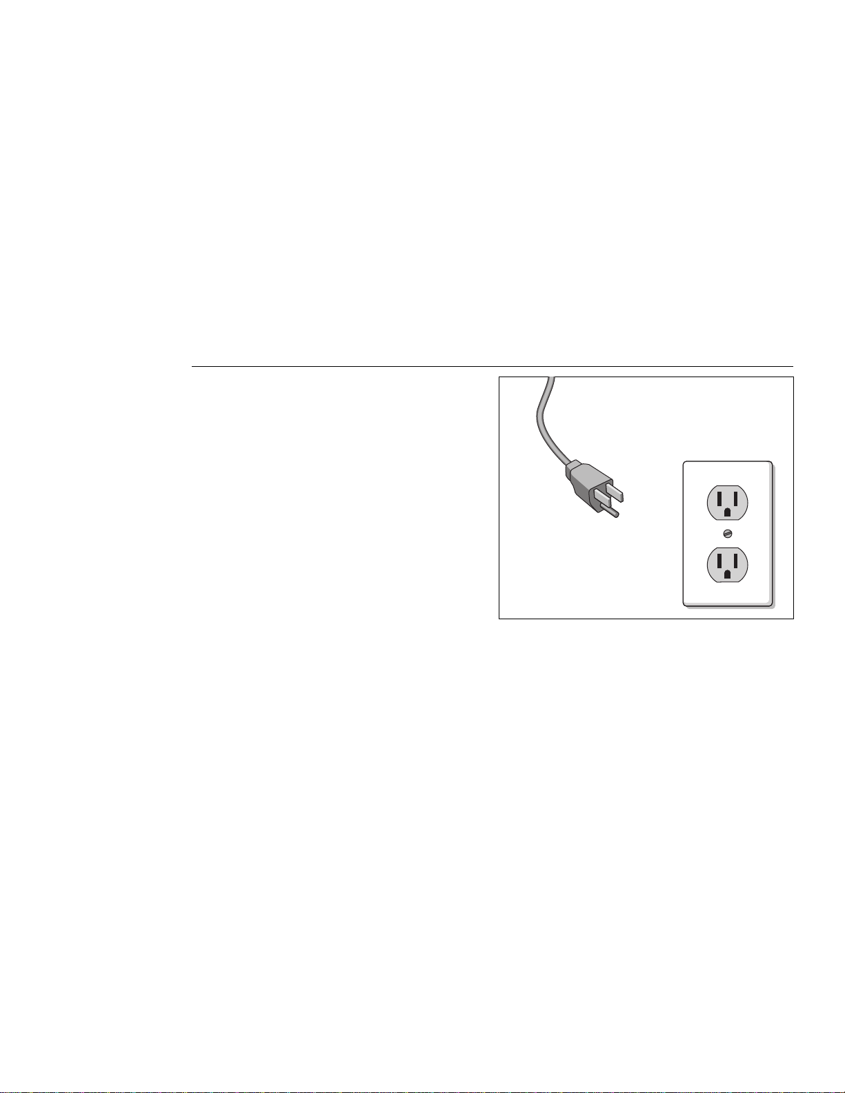
The treadmill is for use on a nominal 120-volt circuit (refer to the WARNING
below and to the
plug that looks like the plug illustrated in Diagram A. Make sure that the
treadmill is connected to an outlet having the same configuration as the plug.
No adapter should be used to connect the treadmill to a power outlet or power
transformer. If the treadmill must be reconnected for use on a different type of
electrical circuit, the reconnection should be made by qualified service
personnel.
Installation Requirements
on page 4) and has a grounding
Diagram A
Proper grounding
plug and power
outlet for 120v
connection
WARNING
This product is for use on a circuit (1) rated for more than 15 amps and is for
use on a circuit having a nominal rating of 120 volts or (2) having a nominal
rating of more than 120 volts and is factory-equipped with a specific electric
cord and plug to permit connection to a proper electric circuit. Make sure that
the product is connected to an outlet having the same configuration as the plug.
No adapter should be used with this product. If the product must be
reconnected for use on a different type of electric circuit, the reconnection
should be made by qualified service personnel.
ATTENTION: Haute Tension
Débranchez avant de réparer.
Safety Information—Save These Instructions
page 5
Page 6

Before You Begin 7
1
2
3
About this Manual 7
Unpacking the M9.20 or M9.20s Treadmill 8
Setting Up the M9.20/s Low Impact Treadmill 10
Installation Requirements 10
Assembly Instructions 11
Checking the Alignment of the Running Belt 17
Using the M9.20/s Low Impact Treadmill 18
Understanding the Electronic Console. 18
Keys on the Electronic Console 19
Using the Magnetic Safety Key 21
Pausing and Ending Your Workout 21
Working Out on Your M9.20/s Treadmill 22
4
5
Using the Manual Course Mode 24
Changing the Interval Course Profile 24
Using the Weight Loss Mode 26
Changing the Display to U.S. Standard or Metric 27
Selecting the Time or Distance Prompt 28
Using a Preprogrammed Course on the M9.20s 29
Creating Custom Courses on the M9.20s 32
Deleting Custom Courses on the M9.20s 33
Getting the Most Out of Your Workout 34
How Hard Should I Exercise? 35
How Long Should I Exercise? 36
How Often Should I Exercise? 36
Maintaining the M9.20/s Low Impact Treadmill 37
Cleaning the Treadmill 37
page 6
Aligning the Running Belt 37
Adjusting the Tension of the Belt 39
Obtaining Service 39
Page 7

Before You Begin
1
Thank you for purchasing one of the most technologically advanced electronic
treadmills available: the M9.20 and M9.20s Low Impact Treadmills. These
treadmills feature two of the most sophisticated and beneficial technologies
Precor has ever created:
Footplant Technology
Ground Effects allows the treadmill running bed to “float” on specially
formulated elastomeric springs, which cushion impact and control lateral
motion without diminishing the bed’s lively, responsive feel. Because it’s fully
suspended, the bed provides optimum shock absorption anywhere your feet
land, not just in the center of the running area.
Integrated Footplant Technology (IFT) is a microprocessor-regulated motor
control system. This patented technology collects motor and belt speed data,
using it to monitor your workout and enhance your safety and comfort. It
replicates the natural walking and running motion of your feet. By allowing
slight, natural speed variations throughout your stride, Precor treadmills reduce
shock and pounding to your body.
The M9.20 Low Impact Treadmill offers an easy-to-understand electronic
console that gives motivating feedback about your workout. Professionally
designed exercise options incorporate the latest in exercise science. Three
different modes enhance your workout capabilities: Manual, Interval, and
Weight Loss.
Ground Effects Low Impact System
. Both are true breakthroughs in technology.
and
Integrated
The M9.20s combines all the benefits of the M9.20 and provides an additional
feature: Program mode. Ten factory-programmed courses provide variety to
help motivate you during your workout.
The M9.20 and M9.20s Low Impact Treadmills have many unique features
which set them apart from conventional treadmills. To maximize your use of
the M9.20 and M9.20s treadmills, please study this guide thoroughly.
About this Manual
This manual explains how to assemble, use, and maintain the M9.20 and
M9.20s (hereafter titled, M9.20/s) Low Impact Treadmills. The following
conventions are used in this manual:
“Note:” Contains additional information that applies to the preceding text.
“Important:” Indicates information to which you should pay special attention.
“CAUTION:” Indicates steps or information necessary to prevent harm to
yourself or damage to the equipment.
“WARNING:” Provides instructions to prevent electrical damage to the
equipment and prevent injuries to yourself or others.
“DANGER:” Indicates steps you must take to prevent electrical shock.
page 7
Page 8

Unpacking the M9.20 or M9.20s Treadmill
The M9.20 or M9.20s treadmill is carefully tested and inspected before
shipment. Precor ships the unit in six pieces as listed below:
• running bed assembly
• lift column assembly
• electronic console display
• handrails
• lift column trim
• owner’s manual, limited warranty card, and hardware kit (The hardware kit
is shown in Diagram 1.)
CAUTION: This unit weighs over 160 pounds. To avoid injury and to
ensure the safety of the unit and yourself, get adequate assistance before
dropping the sidewalls of the box and sliding the running bed assembly
out of the box. Do not lift the running bed from the box.
Carefully unpack the pieces of the treadmill and lay them on the floor near the
location where you plan to use the treadmill. At this time, do not cut the cable
tie that runs through the elevation tube and the lift column. The elevation tube
is calibrated at the factory and the plastic cable tie prevents excessive
movement during shipment.
page 8
Page 9
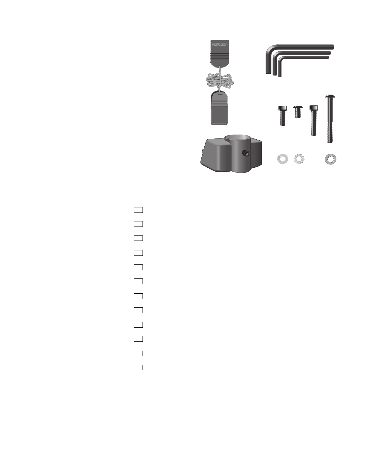
Diagram 1
Hardware kit
J
I
H
L
BA
D
C
K
GF
E
After unpacking the treadmill, open the hardware kit (refer to Diagram 1) and
make sure that you have the following items:
(A) five frame-to-base plate bolts
(B) four bolts–upper handrail clamp
(C) three upper handrail clamp screws
(D) two lower handrail clamp screws
(E) two internal star washers
(F) two external star washers
(G) five split lock washers
(H) one 5/32" hex key—upper and lower handrail clamp
(I) one 3/16" hex key—frame-to-base bolts
(J) one 1/4" hex key—belt tracking and tension adjustment
(K) two lower handrail clamps
(L) one magnetic safety key
If any items are missing, contact the dealer from whom you purchased the
treadmill, or call 1-800-4-PRECOR for the dealer nearest you.
Important: The packaging for this equipment was designed to protect it during
shipment. If you plan on moving in the near future, please store the original
packaging in a safe place.
page 9
Page 10

Setting Up the M9.20/s Low Impact Treadmill
2
You do not need any special knowledge or experience to set up a M9.20 or
M9.20s Low Impact Treadmill. However, you must review and follow the
instructions in this manual. If you do not assemble and use the treadmill
according to the following guidelines, you could void the Precor limited
warranty.
Note: Throughout this manual reference is made to the M9.20/s. The M9.20/s
designation indicates that the information you are reading applies to both the
M9.20s and the M9.20 treadmills.
Installation Requirements
Follow these installation requirements when installing the treadmill:
• Fill out and mail the limited warranty card. The serial number is printed
on a label located underneath the treadmill on the left, rear corner of the
running bed. The best time to locate and write the serial number onto the
limited warranty card and in this manual is while the treadmill is on its side
during the assembly process. Refer to
• Set up the M9.20/s treadmill on a solid, flat surface. Do not install the
treadmill on deeply padded, plush, or shag carpeting due to possible
damage to the carpet and machine. If the treadmill is installed in a carpeted
area, place a piece of heavy cardboard, plywood, or other solid, smooth,
flat surface under the unit to protect the carpet and treadmill. If the floor is
not even, the running belt will not track properly. Refer to
Alignment of the Running Belt,
page 11.
Obtaining Service
, page 33.
Checking the
page 10
• Locate the treadmill at least 4 feet from walls and furniture. Be sure to
provide ample space in front of the machine to allow easy access to the
ON/OFF switch. Open space to the sides and back of the machine makes
for a safer mount and dismount and easier belt adjustment.
• Use a standard 120-volt household outlet. Precor recommends that you
plug the treadmill into an outlet with a dedicated 20 amp house circuit
breaker. The treadmill is equipped with a 20 amp circuit breaker to protect
the electrical and electronic components from sustained overloads, and an
integral 3-prong grounded plug to provide for your safety and to protect the
machine.
CAUTION: Do not remove or otherwise bypass the 3-prong plug with an
adapter or extension cord in order to use a non-grounded outlet. Electrical damage can occur if the treadmill is connected to an improper power
source.
Page 11
Assembly Instructions
To assist you in the assembly of the treadmill, the items in the hardware kit
shown in Diagram 1, correspond to a particular letter in the alphabet. These
letters appear throughout the assembly instructions. Refer to Diagram 1 while
performing the steps below.
To assemble the M9.20/s treadmill, take the following steps:
1. Locate the power switch at the front of the treadmill. Make sure that the
power switch is in the OFF position and that the treadmill’s power cord is
unplugged. Do not assemble the M9.20/s treadmill if it is plugged in.
CAUTION: Do not try to assemble the treadmill by yourself. Because
of the weight of the treadmill and its parts, get additional help from
other people before performing the following steps.
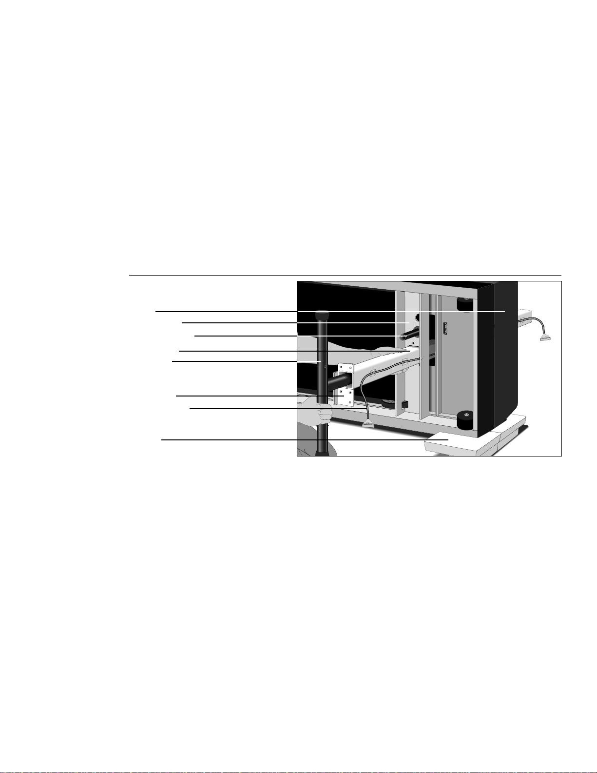
Diagram 2
Hood
Crossbeam
Elevation tube
Lift column
Crossbar
Base plate
Ribbon cable
Blocks
Install lift
column
2. Obtain appropriate assistance to lay the treadmill on its left-hand side.
Placing the foam blocks on the hood of the treadmill, as shown in
Diagram 2, helps elevate the treadmill and keep pressure off the hood
and side rail during assembly. Due to the rounded corners on the side rail,
one assistant will need to balance the treadmill on its side, while another
assistant helps you install the lift column assembly.
Note: Right and left are determined while standing to the rear of the
treadmill facing toward the hood.
3. Pick up and rotate the lift column assembly so that the crossbar is at a 90
degree angle to the base of the treadmill and the hole inside the crossbar is
on the same side as the elevation tube. If necessary, remove the lower
cable connector from the hole inside the crossbar.
4. Slide the crossbar a few inches out of the lift column. Insert the top of the
lift column assembly into the crossbeam. Push the lift column through until
the base plate is flush with the crossbeam. Have your assistant support the
far end of the lift column.
page 11
Page 12
5. Align the five holes in the lift column assembly base with the five holes in
the crossbeam. While your assistant holds the lift column assembly firmly in
place, put a split lock washer (G) on each of the five frame-to-base plate
bolts (A). Insert the bolts into the five holes and finger-tighten.
6. Using the hex key (I) provided, begin to tighten the five bolts. Alternate
between each one, until the base plate is snug up against the crossbeam.
Do not overtighten the bolts.
7. Clip the tie wrap holding the clevis pin in the elevation tube. Remove the
clevis and hitch pins. Due to the sensitivity of the lift calibration, do not
rotate the elevation tube more than 90 degrees in either direction.
8. Carefully align the mounting holes on the crossbar and elevation tube and
slide the elevation tube into the crossbar. Insert the clevis pin (head of the
clevis pin should be toward the rear of the treadmill) through both holes
and re-attach the hitch pin.
Note: The lift is elevated to a 1 percent incline for ease of assembly. The
functioning and accuracy of your lift mechanism depends on properly
installing the clevis and hitch pins.
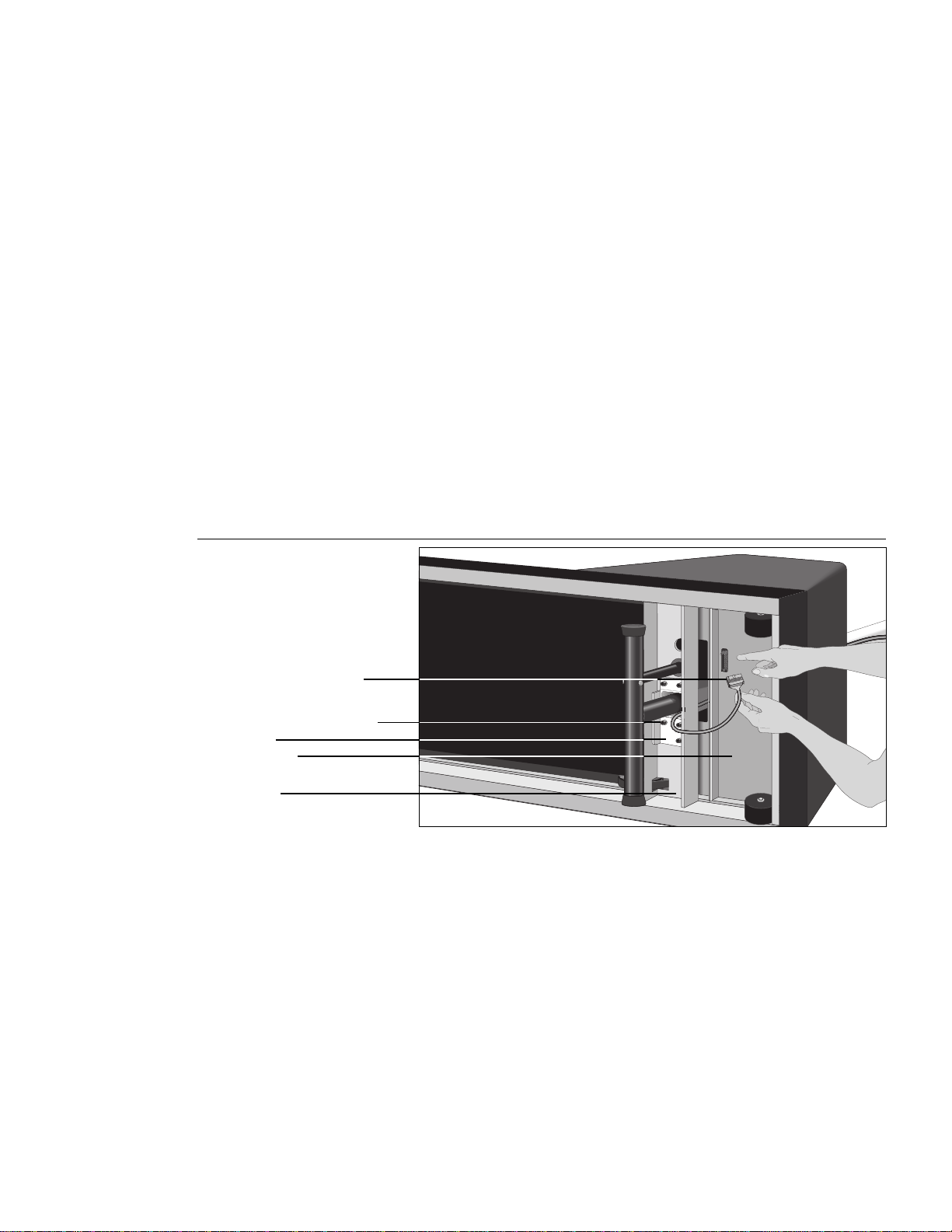
Diagram 3
Plug
connector
into lower
board
Ribbon cable connector
Frame-to-base plate bolts
Base plate
Motor chassis
Crossbeam
9. Route the ribbon cable as shown in Diagram 3, so that you have easy
10. Align the tab on the ribbon cable connector with its counterpart located on
access to the receptacle on the motor chassis.
the receptacle in the motor chassis. Plug the connector into the receptacle.
See Diagram 3. The plastic flanges on the receptacle should clip onto the
connector when you plug it in. Since the connector is designed to engage
in one direction only, do not force the connector into the receptacle.
page 12
11. Have your assistants help you return the treadmill to an upright position, so
that the base is flat on the floor.
Page 13

Diagram 4
CAUTION
Keep hands and clothing away from
bed, belt and rear roller when treadmill
is in operation. As with any power
drivern equipment, DO NOT allow
children and persons unfamiliar with
operation on or near this treadmill.
Always straddle belt when starting
the treadmill. Step onto belt only at
speeds 1mph and slower.
Handrail clamp
Lift column
Ribbon cable
Install
upper
handrail
clamp
12. Place two external star washers (F) onto two of the upper handrail clamp
bolts (B) and have your assistant help you place the handrail clamp into the
groove on the lift column. Align the upper handrail clamp with the mounting
holes on the lift column. See Diagram 4.
13. Insert the bolts (B) through the handrail clamp and into the lift column.
Tighten the bolts securely with the hex key (H) provided.
14. Carefully route the ribbon cable through the slot on the left-hand side of the
handrail clamp.
Note: Right and left are determined while standing to the rear of the
treadmill facing toward the hood.
15. If your hands are dirty, wash your hands before continuing to the next step.
This will help keep the electronic console display clean.
Diagram 5
Attach
cable to
display
Connector
Plastic flange on receptacle
Ribbon cable
16. Hold the electronic console over the handrail clamp to attach the ribbon
cable connector into its receptacle. Align the tab on the ribbon cable
connector with its counterpart located on the receptacle and plug the
connector into the receptacle using your fingers as shown in Diagram 5.
The plastic flanges on the receptacle should clip onto the connector when
you plug it in. If, at a later date, you need to disengage the connector, push
the flanges off of the connector and use your fingers to pull the connector
away from its receptacle. Note that the connector is designed to engage in
one direction only.
Do not force the connection
INCLINE
.
page 13
Page 14

Diagram 6
Handrail clamp
Electronic console
Ribbon cable
Lift column
Attach electronic
console to
handrail clamp
17. Align the electronic console mounting holes with the handrail clamp. Mount
the electronic console onto the handrail clamp by placing the two external
star washers (F) onto the two handrail clamp bolts (B). See Diagram 6.
Insert the bolts through the base of the handrail clamp and into the electronic console. Tighten the bolts securely with the hex key (H) provided.
18. Carefully push the excess cable up inside the handrail clamp compartment.
Check to be sure that the cable forms a smooth loop. If the cable is
pinched or damaged by improper installation, it will not be covered by the
limited warranty.
Diagram 7
Upper handrail
clamp
Trim strip
Electronic
console display
Upper handrail
Upper handrail
clamp
Cable tie & fastener
Ribbon cable
Install
upper
handrails
19. Insert the upper end of a handrail into the upper handrail clamp until the
black foam wrap just touches the clamp as shown in Diagram 7. Repeat
this step for the other handrail.
Note: Look underneath the handrail clamp and make sure that the
handrail ends meet in the middle of the clamp. Re-adjust the handrails,
if necessary.
page 14
20. Insert the three upper handrail clamp screws (C) into the upper handrail
clamp and finger-tighten.
Do not tighten the screws more than finger tight
at this point.
Page 15

Diagram 8
Handrail
Side rail
Lower handrail flange
Lower handrail clamp
Attach lower
handrails
21. To mount the lower portion of the handrails, refer to Diagram 8 while taking
the following steps:
Note: Perform the following steps on one side of the treadmill before
proceeding to the other side.
a. Slide the lower handrail flange along its guide rail until it is aligned with
the handrail mounting bolt hole. The flange should line up with the
seam in the side rail label.
b. Position the lower handrail clamp onto the flange, align the screw
holes, and push the clamp into place.
c. Place the lower portion of the handrail into the clamp. You may need to
push the lower handrail clamp down along its track to securely seat the
end of the tube into the clamp.
d. Put an internal star washer (E) on the lower handrail clamp screw (D),
align the screw holes, and finger-tighten the screw.
e. To secure the handrail inside the clamp, use the hex key (H) provided.
Do not overtighten the screw or damage may occur to the clamp.
Note: After extensive use, vibrations from the treadmill may cause the
clamp to loosen. You may need to periodically inspect the screws and,
if necessary, tighten the handrail clamp screws using the hex key (H)
provided.
f. Proceed to the other side of the treadmill and follow steps a through e
to complete the installation of the lower handrails.
22. Return to the upper handrail clamp, look underneath the clamp to be sure
that the handrail ends meet in the middle of the clamp, re-adjust the
handrails if necessary, and
tighten the screws securely using the
hex key (H) provided.
page 15
Page 16

Diagram 9
Notched end
of trim strip
Velcro strips
Trim strip
Ribbon cable
Lift column
Attach trim strip
to lift column
23. Attach the lift column trim by following these steps. While performing these
steps, refer to Diagram 9 for further clarification.
a. Position the trim strip so that the notched end points up. See
Diagram 9.
b. Insert the base of the trim through the opening in the hood.
c. Raise the trim until the notched end of the trim touches the underside
of the upper handrail clamp. Be careful to maintain vertical alignment of
the trim with the lift column.
CAUTION: Make sure that the ribbon cable is situated in the trim’s
center slot before you take the next step. Cables crimped or
pinched due to inaccurate assembly may not be covered by the
limited warranty.
d. While maintaining alignment, attach the trim by pressing firmly against
the lift column until the hook and loop pads fasten securely to each
other.
24. If you need to move the treadmill, ask for assistance from one or more
persons. Roll the treadmill on its front wheels to the new location by lifting
the rear end of the unit.
CAUTION: Do not remove the 3-prong plug or otherwise bypass it
with an adapter in order to use a non-grounded outlet.
25. Plug the treadmill into a standard 120v household outlet. Make sure that no
other appliances use the same circuit as the treadmill.
26. Continue on to
Checking the Alignment of the Running Belt
on the following
page to complete the installation of the M9.20/s treadmill.
page 16
Page 17

Checking the Alignment of the Running Belt
The belt is aligned at the factory before shipment. However, during shipment
or by using the treadmill on an uneven surface, the belt might move off center.
Proper belt alignment is important because it allows the belt to remain
centered and assures smooth operation.
Follow these steps to check the alignment:
CAUTION: Do not walk on the running belt during this procedure.
1. On the electronic console, move the magnetic safety key to the ACTIVATE
position. Locate the ON/OFF switch at the front of the treadmill and turn
ON the treadmill.
2. Stand beside the treadmill and answer the standard start-up questions as
instructed below:
a. At the “ENTER WEIGHT” prompt, use the arrow keys to specify a
weight and press the SCAN/ENTER key.
b. At the “SELECT COURSE” prompt, use the arrow keys to select
“MANL” (Manual) mode and press SCAN/ENTER.
3. Continue standing next to the treadmill and bring the running belt up to a
speed of 2 miles per hour by pressing the SPEED key.
CAUTION: If you hear or notice any chafing or the running belt
appears to be getting damaged, stop the running belt immediately
by pressing the STOP key.
4. Walk to the back of the treadmill and observe the belt as it moves (watch
for a couple of minutes).
If the running belt,… Then,...
tracks centered on the running surface the belt is functioning
correctly and no adjustment
is necessary.
runs or drifts off center you need to adjust the belt;
see
Aligning the Running Belt
in Chapter 5.
Important: If you notice that the belt needs alignment, make the adjustments at once. Failure to do so might cause the belt to tear or fray which is
not covered by the limited warranty.
5. Press STOP to stop the running belt.
If the belt is functioning correctly, the M9.20/s treadmill is ready to use. If the
belt needs alignment, refer to
Aligning the Running Belt
for instructions before
using the treadmill.
page 17
Page 18

Using the M9.20/s Low Impact Treadmill
3
As simple as using the M9.20/s treadmill might seem, you should read this
section so that you can use it safely and effectively. This section provides the
basic information you need for exercising on your treadmill, including the
following:
• a brief description of the electronic console
• instructions for using the magnetic safety key
• instructions for pausing or ending your workout
• instructions for exercising on the treadmill
• information about using Interval, Weight Loss, and Program modes
• instructions for changing the display from U.S. Standard to Metric
• information regarding the preprogrammed courses on the M9.20s
Understanding the Electronic Console
The electronic console lets you control your M9.20 or M9.20s treadmill session.
As you work out, the electronic display provides constant feedback about your
progress. Information about distance covered, elapsed time, speed, calories
burned, and degree of incline is available at any time. Diagram 10 shows an
example of the M9.20s electronic console.
page 18
Diagram 10
M9.20s electronic
console display
Manual Course - Change your speed and
incline as you exercise.
Interval Course - Alternating rest and work
intervals maximize aerobic conditioning.
Weight Loss Course - 28 minute program
maximizes caloric burn.
Walking Courses - Segments = 0.05 miles.
1
2
3
Running Courses - Segments = 0.1 miles.
1
2
3
Custom Courses - Create and store two.
CAUTION
Keep hands and clothing away
from bed, belt, and rear roller when
treadmill is in operation. Do not
allow children near treadmill without
supervision. Do not allow children
and people unfamiliar with operation
on or near this treadmill. Always
straddle the belt when starting the
treadmill. Step onto the belt only at
speeds 1 mph and slower.
WARNING
Remove safety key when not in use
and store out of reach of children.
ERGO/SMART
SPEED
INCLINE
DISTANCE
TIME
SPEED
CALORIES
INCLINE
SCAN
STOP
HOLD TO RESET
ACTIVATE OFF
WARNING
Remove safety key when not in use and store
out of reach of chinldren.
SCAN
ENTER
The indicator lights on the electronic console show you what information is
being displayed. Information from five distinct fields as shown in Diagram 10
can appear: DISTANCE, TIME, SPEED, CALORIES, and INCLINE.
Note: The M9.20 electronic console is very similar to the M9.20s. The course
label on the left of the console (in Diagram 10) does not appear on the M9.20
console.
Page 19

When you are working out, if the display is set to “scan” two indicator lights
appear to the left of the word SCAN on the display and remain stationary while
you are in the SCAN mode. Another two indicator lights appear next to the field
that is being displayed. The indicator lights move sequentially through each
field every time a new field appears on the display.
DISTANCE
TIME
SPEED
CALORIES
INCLINE
The distance you have travelled appears once you begin a workout. Distance
can appear in miles or kilometers. If you bought your treadmill in the U.S., it is
programmed at the factory to display the U.S. standard units of measure. If you
wish to change the display, you can follow the instructions found in
the Display to U.S. Standard or Metric
you can travel in a single workout is 99.99 miles (161 km) before the odometer
resets at 00.00 and begins over again.
During your workout, a time (00:00) display appears automatically and stops
whenever you stop walking or running. As you work out, you will notice that the
time starts at zero and counts up when you use manual, interval, or weight loss
modes. Time appears in minutes and seconds until you reach 90 minutes
(during a single workout), then it appears in hours and minutes.
Once you begin a workout, the speed at which you are travelling appears in
this display. Your speed can appear in miles per hour (.5 to 9 mph) or
kilometers per hour (.8 to 14 kph). If you wish to change the display, you can
follow the instructions found in
Changing the Display to U.S. Standard or
in this manual. The maximum distance
Changing
Metric.
When you enter your accurate weight, the number of calories you are burning
appears in this display while you work out. At the end of your workout, the total
calories burned is displayed.
The M9.20/s treadmill provides a range of inclines from 1% to 10%. You can
change the incline and increase or decrease the level of your workout by
pressing the INCLINE keys.
SPEED
Keys on the Electronic Console
The keys on the electronic console let you change the speed and incline, stop
or reset the treadmill and its displays, and set the SCAN mode or display a
particular feature. Each key and its function is explained below:
Use the SPEED keys to change belt speed. Belt speed starts at .5 miles
per hour (mph) and increases in .1 mph (.2 kilometers per hour) increments
while you hold the key. The M9.20/s treadmill allows you to increase speed
up to 9 mph (14 kph). When you decrease speed, belt speed decreases at a
rate of .1 mph (.2 kph) while you hold the key.
Anytime during your workout, you can view your speed in minutes per mile (or
kilometer). In other words, you can see how many minutes it takes you to walk
or jog a mile (or kilometer). To use this feature, simultaneously press both
SPEED keys and the information will appear on the screen. When you
release both keys, the speed display returns to the per hour measurement you
originally set. See
Changing the Display to U.S. Standard or Metric.
page 19
Page 20

INCLINE
Use the INCLINE keys to change the running bed incline up to 10 %.
Simply, press the appropriate arrow key until the desired percent of incline is
displayed. You can change the incline anytime during a workout.
When you change incline, note that the number shown on the display changes
faster than the elevation motor can respond. Once you select an incline, there
is a brief delay before the running belt reaches that elevation.
Important: Whenever you change the incline, always use one hand to hold
onto the handrail.
STOP
HOLD TO RESET
SCAN/ENTER
To pause during your workout or to end your workout, press the STOP key.
The running belt gradually slows to a stop and the displays on the console
show your workout statistics.
To return to the start-up prompt, press and hold the HOLD TO RESET key for a
few seconds. Your workout statistics are added to the cumulative totals.
The SCAN/ENTER key has two functions which let you:
• alternate between the displays every few seconds (SCAN)
• select the specific workout information you want to display (ENTER)
• address each prompt and “enter” the information into the treadmill’s
memory (ENTER).
SCAN
In general, the electronic console display is set to scan, so the different
features (DISTANCE, TIME, SPEED, CALORIES, and INCLINE) alternately
appear in sequence every few seconds. A pair of lights next to the word
“SCAN” indicates that you are in SCAN mode. Another pair of lights on the
display indicate which feature is currently displayed.
ENTER
page 20
ACTIVATE
OFF
To cause a specific feature, such as the SPEED, to continuously appear on the
display, press the ENTER key until the two round indicator lights appear next to
the word SPEED.
To specify a weight, select a workout mode, or reset U.S. Standard or Metric
configurations, you need to use the ENTER key.
If the magnetic safety key is not in the ACTIVATE position, you cannot turn
ON the treadmill. If used properly, the magnetic safety key helps to protect you
from injury during your workout. Attach the magnetic safety key to your clothing
prior to stepping onto the running belt and beginning your workout. If you
encounter a problem during your workout, simply pull on the safety key’s cord
to stop the running belt. When the magnetic safety key is removed from the
ACTIVATE position, it trips the treadmill’s circuit breaker, turns OFF the treadmill and gradually slows the running belt to a stop.
After completing your workout by pressing the STOP key, move the magnetic
safety key to the OFF position. This turns OFF the treadmill. To prevent
unauthorized use, remove the magnetic safety key and store it in a safe place.
Page 21

Using the Magnetic Safety Key
The magnetic safety key lets you stop the treadmill’s running belt. Use this key
in an emergency or when you are finished exercising. Pulling the key off the
console or moving it to the OFF position, has the same effect as turning OFF
the treadmill using the ON/OFF switch. Once you remove the key from the
ACTIVATE position, the running belt slows to a gradual stop.
Important: Always attach the magnetic safety key to your clothing before each
workout. Use the clip provided on the end of the cord.
Diagram 11
Electronic
console display
Magnetic key
Magnetic safety
key on the M9.20s
console
Manual Course - Change your speed and
incline as you exercise.
Interval Course - Alternating rest and work
intervals maximize aerobic conditioning.
Weight Loss Course - 28 minute program
maximizes caloric burn.
Walking Courses - Segments = 0.05 miles.
1
2
3
Running Courses - Segments = 0.1 miles.
1
2
3
Custom Courses - Create and store two.
CAUTION
Keep hands and clothing away
from bed, belt, and rear roller when
treadmill is in operation. Do not
allow children near treadmill without
supervision. Do not allow children
and people unfamiliar with operation
on or near this treadmill. Always
straddle the belt when starting the
treadmill. Step onto the belt only at
speeds 1 mph and slower.
WARNING
Remove safety key when not in use
and store out of reach of children.
ERGO/SMART
SPEED
INCL INE
DISTANCE
TIME
SPEED
CALORIES
INCLINE
SCAN
STOP
HOLD TO RESET
ACTIVATE OFF
WARNING
Remove safety key when not in use and store
out of reach of chinldren.
SCAN
ENTER
Before you can turn ON the treadmill, you must move the magnetic safety key
to the ACTIVATE position on the electronic console. See Diagram 11. The
treadmill's ON/OFF switch cannot be turned ON unless the safety key is in this
position.
Pausing Your Workout
You can pause your workout at any time by pressing STOP. To continue your
workout, use the SPEED keys to restore your speed.
Ending Your Workout
To end your workout, press STOP. This slows the treadmill’s running belt to a
gradual stop. The display then begins to scan and allows you to review the total
time, distance, and caloric burn of your workout.
When using Interval Mode, you can cool down before ending your workout by
changing to Manual Mode; simply press STOP twice in quick succession.
To reset the displays on your treadmill, press and hold the HOLD TO RESET
key for several seconds. This clears all data from the display, and adds your
workout statistics to the cumulative total.
page 21
Page 22

Working Out on Your M9.20/s Treadmill
Before using your treadmill, we recommend that you follow these instructions
and go through a preliminary demonstration of the treadmill. Then you will be
familiar with the treadmill when you begin your workout.
When using the treadmill, follow these general guidelines:
• At the beginning of a workout, take several minutes to bring your heart rate
into your training zone, which is shown in Diagram 14 on page 29.
• After your workout, walk slowly for several minutes to cool down your body
and lower your pulse rate.
• Using the clip provided, attach the magnetic safety key to your clothing
before each workout. Then, if you encounter difficulties or want to end your
workout, you can easily stop the running belt by pulling on the cord.
• Gently stretch your lower body and back before and after a workout to help
prevent stiffness or soreness.
Photo 1
Working out
on the M9.20/s
To use the treadmill, follow these instructions.
page 22
CAUTION: If this is the first time you have operated this treadmill, DO
NOT STAND on the running belt until you become familiar with M9.20/s
operation.
1. On the electronic console, place the magnetic safety key in the ACTIVATE
position. Walk to the front of the treadmill and turn ON the treadmill using
the ON/OFF switch. The treadmill's ON/OFF switch will not turn ON unless
the safety key is in the ACTIVATE position.
Page 23

2. Straddle the running belt with your feet firmly planted on the right and left
side platforms. Stand close enough to the electronic console so you can
extend your arms and touch the keypad.
3. Using the clip provided, securely attach the magnetic safety key to your
exercise clothing at your waistline where it will not interfere with your
workout.
4. When you see “ENTER WEIGHT” scroll across the display, specify your
weight using the keys. When the correct weight is displayed, press the
ENTER key.
The number on the display moves in 5-pound (2 kg) increments up
or down, depending on the arrow key pressed. You must specify this
information so the treadmill can provide accurate feedback about calories
burned during a workout.
Once your weight is specified, you may not need to enter it again. The
treadmill automatically remembers the last weight entered. At your next
workout, simply press ENTER at the “ENTER WEIGHT” prompt.
(If another person has used the machine and changed the weight, you
will need to re-enter your weight as described in this step.)
5. At the “SELECT COURSE” prompt, choose your workout mode, either
Manual (MANL), Interval (INTV), Weight Loss (WT.LS.), or one of the
M9.20s preprogrammed courses. Press the keys until you see the
desired mode or course number appear on the display, then press ENTER.
For more information about the different modes, read the following pages.
Once you specify the mode, the treadmill automatically remembers it. If
no one else uses the treadmill or makes any changes before your next
workout, you can simply press ENTER at the “SELECT COURSE” prompt
and activate the same mode.
Important: If you choose the INTV mode, refer to
Course Profile
before continuing on to the next steps.
Changing the Interval
6. Hold onto the handrail with one hand and press the SPEED key with the
other hand. Step onto the running belt while it is at or below 1 mph. Once
you are comfortable with the walking or running speed, you may remove
your hands from the handrail.
Note: To pause during your workout session, press the STOP key. The
displays on the console stop updating. See
Ending Your Workout
for more information. Remember to hold onto the
Pausing Your Workout
or
handrail when using the electronic console and when slowing down or
stopping the running belt.
7. When you are finished exercising, hold onto the handrail and press STOP.
The treadmill’s running belt slows to a stop. You can then review your
workout results as the display scans through DISTANCE, TIME, and
CALORIES.
Note: Always allow yourself a cool-down period of a few minutes before
bringing the running belt to a complete stop.
page 23
Page 24

8. If desired, after reviewing the displays, reset them to zero by pressing and
holding HOLD TO RESET for several seconds.
9. Detach the magnetic safety key cord from your clothing and place the
safety key in the OFF position on the electronic console. Placing the safety
key in the OFF position trips the circuit breaker and turns OFF the treadmill.
To prevent unauthorized use, remove the safety key from the treadmill and
store it in a safe place.
Using the Manual Course Mode
Manual mode lets you use the treadmill for an indefinite period of time while
controlling the speed and incline of your workout. All of your workout statistics
are compiled and displayed on the electronic console.
To use the manual mode, follow the steps in
Treadmill
ENTER.
. At the “SELECT COURSE” prompt, choose “MANL” and press
Working Out on Your M9.20/s
Changing the Interval Course Profile
Interval training provides numerous benefits. Since interval training segments
the workout into smaller components, a 20- or 30-minute workout seems to
pass more quickly. In addition, studies have shown that it is a more efficient
method for achieving aerobic benefits—you start seeing improved cardiovascular fitness much sooner with less effort. Studies also show that people
who interval train are more likely to stick with their fitness program.
The interval course on the M9.20/s treadmill lets you set the course intervals
according to your training regimen. It alternates between 60 seconds of “Rest”
and 60 seconds of “Work.” During the Rest interval, you can walk or jog slowly;
during the Work interval, you can stride quickly or run. You set the speed for
the first rest and work interval and the software takes over from there, repeating
the intervals throughout the course until you press the STOP key.
At any point during the workout, you can change the speed of the current
interval. For example, if 8 mph is a little faster than you prefer during a Work
interval, simply use the SPEED key to reduce speed. The software
remembers the new speed for the next Work interval.
page 24
To help you monitor your workout, you can set the treadmill’s electronic display
to SCAN. This mode displays a sequential readout on DISTANCE, TIME,
SPEED, CALORIES, and INCLINE.
Note: If you pause your workout during an Interval mode, you must reset the
speed of the mode you were in when you paused your workout. For example, if
you paused your workout during the Rest interval, you must reset the speed for
that interval. In this example, you would not need to reset the speed for the
Work interval since it is stilled stored in memory.
Page 25

Below are some suggestions that may help you incorporate the Interval mode
into your workout:
• If you are starting an exercise program, the Interval mode option can help
you increase your workload gradually. For example, in the beginning, you
may simply want to specify the same speed for both Work and Rest
intervals. Then, to increase your effort level, change to a higher speed for
your Work interval.
• If you are training with the goal of maintaining a constant pace when on
level ground or grade, specify the same speed for both Work and Rest
intervals. Then, gradually increase the incline during the Work interval until
you can maintain a constant pace.
To use the interval course, follow the steps in
Treadmill
. At the “SELECT COURSE” prompt, use the keys to display
Working Out on Your M9.20/s
“INTV,” and press ENTER.
To set the interval for the course, take the following steps:
1. When you see “ENTER REST SPEED & INCLINE” scroll across the
display, stand on the running belt with one hand on the handrail, prepared
to start walking. With your other hand, press the SPEED key until you
reach a comfortable rest speed, either running or walking. Press the
INCLINE or key to specify an appropriate incline. When the desired
speed and incline are displayed, simply continue working out—you do not
need to press ENTER.
Once you reach your desired rest speed and incline, the treadmill returns to
it at the beginning of each rest interval, until you change the speed or
incline, or end your workout.
2. When “ENTER WORK SPEED & INCLINE” scrolls across the display,
specify your work speed (up to 9 mph). With one hand on the handrail, use
the other hand to press the SPEED keys until the desired work speed
is shown. Use the INCLINE or key to set the incline. When you are
comfortable with the rest and work speeds and inclines, you can let go of
the handrail.
Each rest and work interval lasts 60 seconds. The display automatically counts
down to the next interval. When the count reaches 30 seconds, the display
changes and gives information about distance travelled, time elapsed, speed,
calories burned, and percent of incline.
When the treadmill changes intervals, it informs you by scrolling “GOING TO
REST SPEED” or “GOING TO WORK SPEED” across the display.
Using the interval course mode, you can cool down before ending your workout
by pressing STOP twice in quick succession. The treadmill enters Manual
Mode, letting you specify the speed of your cool-down period.
page 25
Page 26

Using the Weight Loss Mode
The Precor Weight Loss mode program incorporates the latest findings on fatburning and weight loss through exercise. It is based on research at the worldrenowned Cooper Institute for Aerobics Research.
The Weight Loss mode is similar to the interval course program on your
M9.20/s treadmill. The Weight Loss mode program provides a 28-minute
workout with inclines preset to a minimum level for the 4-minute rest interval
and a maximum level for the 4-minute work interval.
You can adjust the incline during any interval segment. However,
incline will reduce the effectiveness of your weight loss program
changing the
. Any time you
adjust the incline, the software returns to the default incline of minimum or
maximum at the beginning of the next rest or work interval. The treadmill alerts
you of upcoming incline or interval changes by scrolling messages across the
display.
The Weight Loss mode is designed to help you burn the most fat during a
28-minute workout, while minimizing the risk of discomfort and injury. Performed three or four times a week, the weight loss mode will help you reach
your ideal weight and fitness level quickly and efficiently.
CAUTION: Before beginning any fitness program, you should have a
complete physical examination from your personal physician.
To use the Weight Loss mode, follow the steps found in the section titled
Working Out on Your M9.20/s Treadmill.
When the electronic console display
prompts you to select a mode, use the keys to select “WT. LS.” and then,
press ENTER.
Note: Be sure to enter your correct weight at the weight prompt. Deviating
from your actual weight reduces the effectiveness of the weight loss program.
page 26
Table 1
Speed calculated
in MPH
Perceived Level of Fitness
Medium Low
5
4
3
2
1
1.3
Speed in miles per hour
0
2.2
3.1
Medium HighMedium
3.6
HighLow
4.5
Page 27

Table 2
Perceived Level of Fitness
Speed calculated
in KPH
Medium Low
6
5
4
3
2
2.1
1
Speed in kilometers per hour
0
3.5
5.0
Medium HighMedium
5.8
HighLow
7.3
Set the speed of the treadmill based on your perceived level of fitness
(low, medium, or high—see Table 1 or Table 2). The incline is preset to
accommodate your level of fitness.
CAUTION: If you are unsure about your level of fitness, start at the
low speed. Do not increase your speed beyond 1.3 mph or 2.1 kph.
Remember, always consult your physician before beginning any new
exercise routine.
If you wish to continue the weight loss program at the end of the 28-minute
period, press the SPEED . The speed remains constant, but the incline
gradually increases to 10% and the preset 4-minute rest and work intervals
continue to repeat until you press the STOP key. If you want to adjust the
speed, press the SPEED or key until the desired speed appears in the
display.
Always monitor your pulse (heart rate) during and at the end of your workout. It
should never exceed 80% of your maximum heart rate or go above your
training zone. Refer to Diagram 14 in
Getting the Most Out of Your Workout
for
your appropriate training zone.
Changing the Display to U.S. Standard or Metric
The M9.20/s treadmill can display speed in either miles per hour (mph) or
kilometers per hour (kph). When the M9.20/s is shipped from the factory, it is
set to display to U.S. Standard units of measure. You can easily change these
settings by taking the following steps:
Note: The M9.20/s treadmill will retain your selection even when it is turned
OFF and unplugged. You can change your selection at any time, simply by
repeating the following steps.
1. Place the magnetic safety key in the ACTIVATE position on the electronic
console. Walk to the front of the treadmill and turn the power switch ON.
(The magnetic safety key must be placed in the ACTIVATE position before
you can turn ON the treadmill.)
page 27
Page 28

2. Straddle the running belt with your feet firmly planted on the right and left
side platforms. (Stand close enough to the electronic console, so that you
can extend your arm and touch the keypad.) Use the clip on the magnetic
safety key and attach it to your clothing at your waistline.
3. At the “ENTER WEIGHT” prompt, simultaneously press and hold the
SPEED key and the SCAN key. The prompt, “PRESS FOR MPH
OR FOR KPH” appears on the display. Release both keys.
4. Use the appropriate SPEED or key to indicate your selection.
You can continue your workout by following the appropriate steps below in
Selecting the Time or Distance Prompt
or turn OFF the treadmill by moving the
magnetic safety key to the OFF position.
Selecting the Time or Distance Prompt
When using a preprogrammed course, you can measure your workout by
distance or time. You see the “SELECT DISTANCE” or “SELECT TIME”
prompt after you enter a course selection. The default measurement is
distance.
To change the prompt, follow the steps above in
Standard or Metric
.
Changing the Display to U.S.
1. After step 4 above, two messages scroll across the display: one confirms
your mph or kph selection and the other states, “PUSH FOR
DISTANCE FOR TIME OR ‘STOP’ FOR ASK.” Press the appropriate
key after answering one of the following if/then scenarios:
If you want,... Then,...
your workout measured by distance press the key
your workout measured by time press the key
the option of selecting time or
distance prior to each workout press STOP
After you press an arrow key, a message scrolls across the display
confirming your selection.
2. Continue with your workout or turn OFF the treadmill by removing the
magnetic safety key from the ACTIVATE position on the electronic console.
If you turn OFF the treadmill, be sure to store the safety key in a safe place
to prevent unauthorized use.
page 28
Page 29

Using a Preprogrammed Course on the M9.20s
To use a preprogrammed course, follow the instructions below. Remember,
when you use the electronic console, hold onto the handrail to maintain your
balance. You should also use the handrail whenever you speed up, slow down,
or stop the treadmill.
CAUTION: If this is the first time you have operated this treadmill, DO
NOT STAND on the running belt until you become familiar with M9.20s
operations. Be sure to read and follow the general guidelines found in
Working Out on Your M9.20/s Treadmill
1. On the electronic console, move the magnetic safety key to the ACTIVATE
position (shown in Diagram 11, page 15). Walk to the front of the treadmill
and turn ON the treadmill using the ON/OFF switch. The treadmill switch
will not turn ON unless the safety key is seated securely in the ACTIVATE
position.
2. Straddle the running belt with your feet firmly planted on the right and left
side platforms. Stand close enough to the electronic console so that you
can extend your arms and activate the keys.
3. Using the clip provided, securely attach the magnetic safety key to your
clothing at your waistline, where it will not interfere with your workout.
prior to using the treadmill.
4. When you see “ENTER WEIGHT” scroll across the display, specify your
weight using any key. When the correct weight is displayed, press
ENTER. This information allows the M9.20s to calculate how many calories
you use during your workout.
The number on the display moves in 5-pound increments up or down,
depending on the arrow key pressed. Use to increase and to decrease
the weight displayed.
Once your weight is specified, you may not need to enter it again. The
treadmill automatically remembers the last weight entered (unless the
treadmill is turned OFF). At your next workout, you restore your weight from
the treadmill’s memory by simply pressing ENTER at the “ENTER
WEIGHT” prompt. However, if someone else has used the treadmill and
made changes prior to your workout, you will need to re-enter your weight.
Note: The prompt “PRESS ENTER TO BEGIN” appears after a few
seconds if you have not chosen a course and pressed ENTER. This
prompt continues to scroll across the display every few seconds until you
press ENTER.
CAUTION: Before beginning any fitness program, you should have a
complete physical examination by your physician. If you are unsure
about your level of fitness, consult your physician. Always start your
workout at the low or “easy” level and work to increase your level of
fitness before performing moderate or advanced workout routines.
page 29
Page 30

Diagram 12
Manual Course
M9.20s course profiles
Change your speed and
incline as you exercise.
Interval Course
Alternating one minute
rest and work intervals.
Weight Loss Course
28 minute program.
Maximizes calorie and
fat burn.
Walking Courses
Each segment equals
0.05 miles.
page 30
Running Courses
Each segment equals
0.1 miles.
Custom Courses
Create and store two of
your own courses.
Page 31

5. At the “SELECT COURSE” prompt, choose your workout course using the
keys: either WALK, RUN, CUST. 1, CUST. 2, MAN’L, INTV, WT.LS.
and then press ENTER. The course you choose takes you through a set
series of incline intervals, with inclines varying according to the level of the
course.
If you choose WALK or RUN a prompt appears asking that you select a
level: (EASY, MODerate, or ADVanced). It is always recommended that
you start a workout at the EASY level.
Diagram 12 on the previous page provides an illustration of the available
preprogrammed courses. The courses combine .5-mile segments with a set
series of inclines. The percent of incline and the frequency with which inclines
are encountered indicate the difficulty of the course. For example, WALK EASY
takes the user through inclines ranging from 0 to 3 percent grade, while RUN
ADV uses inclines in the minimum to maximum range on a more frequent
basis. The software simply repeats the .5-mile segments until the distance or
time limit you set is reached, or you press the STOP key.
Note: If you do not press ENTER to select a course, after 10 seconds the
prompt “PRESS ENTER TO BEGIN” appears. This prompt continues to scroll
across the display every few seconds until ENTER is pressed.
6. At the “SELECT MILES (kilometers)” prompt, specify the length of your
course. Press the arrow keys to choose distance; the display moves in
.5 increments, from .5 to 50 miles (.8 to 80 kilometers). Press ENTER
when the desired distance appears.
Note: You can change the “SELECT TIME” prompt to “SELECT
DISTANCE” if you prefer to measure your workout by distance. Follow
the procedure in
Selecting the Time or Distance Prompt.
If you see “SELECT TIME” scroll across the display, specify the length of
your workout. Press the or key to choose time; the display moves in
1-minute increments, from 5 to 50 minutes. Press ENTER when the
desired time appears.
7. Stand on the running belt with one hand on the handrail, prepared to start
walking. With your other hand, press the SPEED until you reach your
desired speed.
The course will continue until the specified distance or time is reached, or
until the STOP key is pressed. Any time during your workout, you can
change your speed. However, since the incline is pre-set, the incline keys
are disabled.
8. When you are finished working out or you have come to the end of the
course, hold onto the handrail and press STOP. The treadmill will come to
a safe stop. Be sure to remove the magnetic safety key from your clothing
and return it to the OFF position on the electronic console. To prevent
unauthorized use, remove the safety key and store it in a safe place.
Note: If desired, you can cool down before ending your workout by
pressing STOP twice in quick succession. The treadmill will stop and enter
the Manual mode, allowing you to specify the speed and incline of your
cool-down period.
page 31
Page 32

Creating Custom Courses on the M9.20s
You can program the M9.20s and create your own course profiles using the two
custom courses (“CUST. 1” and “CUST. 2”). Programming a custom course is
easy. You just create the custom courses as you work out by determining the
speed and incline for each 0.1 mile segment along the 8-mile maximum course
length. Speed and incline settings are saved once every .1 of a mile which
equals 10 dots on the display. Once you complete your workout, the course is
stored in memory and can be automatically recalled using the same program
number.
To create a custom course, take the following steps:
1. Straddle the running belt and hold onto the handrail with one hand. Use
your other hand to press the keys on the electronic console.
2. When you see “PRESS ENTER TO BEGIN” scroll across the display,
specify your weight using the arrow keys. When the correct weight is
displayed, press ENTER.
3. At the “SELECT COURSE” prompt, choose your custom course: either
“CUST. 1” or “CUST. 2.” Press the or keys until you see the desired
course, then press ENTER.
Note: After pressing ENTER, a prompt scrolls across the display warning
you that the custom course contains set speed and inclines. You are not
to use the course if you are not familiar with it. The following instructions
(5 through 9) assume that you are programming a new custom course.
However, if you want to use the existing custom course, press SPEED
to begin.
Important: After pressing ENTER, clear an existing custom course
profile by simultaneously pressing both the INCLINE keys for at
least 3 seconds. The course profile reverts to a blinking line at 0% incline.
Be cautious about performing this procedure. Once you clear an existing
course profile, you cannot retrieve it.
4. Hold onto the handrail and press the SPEED key. Step onto the running
belt while the speed is at or below 1 mph and begin walking. Use the
INCLINE keys to change the course profile as you walk. The first time
the custom courses appear, the profile appears flat (0 % incline) until you
change it.
page 32
Page 33

5. As you move through the course, you can continue to change the course
profile by using the SPEED and INCLINE keys on the segment that is
blinking. You cannot “go back” to a segment once you move beyond it.
However, you can pause by pressing STOP. The following prompts appear
and scroll across the display:
•“PRESS “ENTER” TO SAVE or A SPEED KEY TO CONTINUE”—
pressing ENTER saves the course profile up to the point (mile or
kilometer) where you stopped and resets any previously saved
program course.
Note: You must program at least .10 mile (10 dots on the display)
before your new course can be saved otherwise the software reverts
back to the existing course the next time you work out in custom
course mode. If an existing course profile extended beyond the
segment where you stopped, it will be discarded.
•“PRESS SPEED-UP TO CONTINUE”—pressing the SPEED key
starts the running belt and allows you to continue from where you left
off. Be sure to hold onto the handrail before pressing SPEED .
6. If you attempt to program the course profile past the maximum distance of
8 miles, the prompt, “END COURSE” appears and scrolls across the
display. The running belt slows to a gradual stop, the incline returns to 0%,
and the prompts appear requesting that you save your changes.
7. Save your changes by pressing ENTER. Once you save your custom
course, you can work out and use the same course over and over by
entering the associated custom course number. The M9.20s can store two
custom courses.
Deleting Custom Courses on the M9.20s
An existing custom course can be deleted by pressing both INCLINE keys
when the custom course profile appears on the display.
Take the following steps to delete a custom course:
1. After answering the start-up prompts and choosing your custom course, a
“CAUTION” message scrolls across the screen indicating that an existing
custom course exists.
CAUTION: Once you press the INCLINE keys to reset the course
profile, you cannot retrieve the old custom course.
2. When the course profile appears on the display, press both INCLINE
keys and hold for at least 3 seconds.
3. A message appears indicating that the custom course profile has been
reset (0% incline and 0 speed).
page 33
Page 34

Getting the Most Out of Your Workout
4
A workout on the M9.20/s Low Impact Treadmill provides excellent and efficient
cardiovascular conditioning, while strengthening and toning all the major
muscle groups in the lower body. Darkened areas in Diagram 13 indicate the
muscles improved.
Diagram 13
1. Trapezius
2. Deltoid
3. Pectorals
4. Rhomboids
5. Triceps
6. Biceps
7. Latissimus Dorsi
8. Forearm Flexors/Extensors
9. Abdominals
10. Erector Spinae
11. Gluteals
12. Hip Flexors
13. Quadriceps
14. Hamstrings
15. Gastrocnemius/Soleus
16. Peroneus Longus/Brevis
Muscles
improved
page 34
To get the most out of each workout, a general understanding of the principles
behind aerobic training is invaluable. The best source of information is your
specialty fitness dealer. In addition to providing information on which exercise
equipment is best for your individual needs, your fitness dealer can provide
useful advice on training, technique, and exercise physiology. Your dealer can
also recommend good books and audio/video tapes on these subjects.
To help you get started in planning and carrying out your fitness program, this
section provides some basic information on aerobic exercise—such as how
hard you should work out, how long each session should be, and how often you
need to exercise to benefit from a regular program.
Page 35

Diagram 14
Training zones
HEART RATE TRAINING ZONE
190
190
180
170
160
150
140
130
YOUR HEART RATE
120
110
100
90
80
70
How Hard Should I Exercise?
185
180
152
148
144
124
120
117
20
25 30 35 40 45 50 55 60 65 70 75
175
170
165
160
155
140
136
132
128
104
124
101
RECOMMENDED TRAINING ZONE
114
110
107
YOUR AGE
150
120
98
145
116
94
140
112
91
135
108
88
MAX.
HEART
RATE
80% OF
MAX.
HEART
RATE
65% OF
MAX.
HEART
RATE
Studies show that to achieve the benefits of aerobic exercise, it is necessary to
work out hard enough to raise your heart rate to a certain minimum level, called
the “training zone.” Your training zone depends on your age and level of
fitness.
Diagram 14 shows your recommended heart rate training zone, which is
calculated using your age and your maximum attainable heart rate. The chart is
based on a resting heart rate of about 72 for males and 80 for females. Your
optimum training zone is between 65% and 80% of your maximum heart rate.
For efficient aerobic exercise, work only hard enough to keep your heart rate in
this zone. You will obtain the greatest fat-burning benefits when you exercise
within the optimum training zone.
Pushing yourself beyond the recommended range, (that is, exercising so hard
that your heart rate rises above 80% of maximum) can overstress your
muscles. To increase cardiovascular improvement, exercise
longer
, not harder.
Keep in mind that this zone is an approximation, to be used as a guideline—
individual heart rates vary according to several physiological factors. To
determine your training zone, find your age on the diagram, and then find the
line where they intersect. For example, if you are 35 years old, your training
zone is between 114 and 140 beats per minute. Remember this zone—this is
the heart rate zone you should try to maintain as you work out.
If you do not have an accurate heart rate monitor, you can determine your heart
rate by taking your pulse at a place that you can reach easily and comfortably
while you exercise. Typical places for measuring heart rate are directly over the
heart on the left side of the chest, on either side of the neck, over the temple, or
on the thumb side of either wrist. Wherever you measure your pulse, make
sure that you use your index and middle fingers—not your thumb. Your thumb
has a strong pulse which can affect your pulse rate reading.
page 35
Page 36

Once you locate your pulse, look at a clock with a second hand, and count the
beats for six seconds. Multiply that number by 10 to determine the total number
of beats per minute. For example, if you count 14 beats over six seconds, the
total number of beats per minute is 140. Compare the total number of beats
with your training zone as identified in Diagram 14. If necessary, increase or
decrease your activity level to bring your heart rate into your training zone. You
can regulate your work level (and heart rate) by changing belt speed and
incline. Remember—your heart rate is the definitive measure of how hard
you are working.
Regardless of your fitness level, avoid doing too much too soon. Running or
walking too fast or choosing too high of an incline are common errors. Give
yourself time to become familiar with your treadmill and to improve your fitness
level. Then you can gradually increase speed and incline to make your workouts more challenging.
How Long Should I Exercise?
The length of each exercise session depends on your fitness level. Exercise
physiologists have determined that, to attain cardiovascular benefits from
exercise, you should maintain your heart rate in its training zone for at least
15 minutes. This is in addition to your warm-up time, and does not include cool
down. You should always allow several minutes to bring your heart rate into the
training zone, by starting out slowly and gradually increasing work level.
Similarly, use several minutes of light exercise after the workout to bring your
heart rate down to near resting level.
The higher your fitness level, the longer you should maintain your heart rate in
the training zone (between 20 and 30 minutes). Beginners should always start
slowly, and gradually bring their sessions up to 20 minutes or more.
How Often Should I Exercise?
Research indicates that aerobic sessions of 20 minutes or more should be
done at least three to five times a week to obtain significant cardiovascular
benefits. Most experts agree that sensible eating habits and regular aerobic
exercise are the keys to weight control and fitness. A recent study, which
tracked several subjects over a period of years, conclusively shows that
exercise, not dieting, is the key factor to long-term weight loss.
page 36
Page 37

Maintaining the M9.20/s Low Impact Treadmill
5
The M9.20/s Low Impact Treadmill requires little maintenance to keep it running
smoothly and efficiently. However, the customer is responsible for the typical
maintenance tasks such as, cleaning the treadmill and adjusting the running
belt. If you fail to maintain the treadmill as described below, it could affect or
void the limited warranty.
CAUTION: Turn OFF the treadmill and disconnect the power cable before
performing most maintenance tasks.
Cleaning the Treadmill
Your Precor treadmill relies on low friction for efficient operation. To keep the
friction low, the treadmill must be as clean as possible.
Before a workout, use a damp, soft, clean cloth to clean the side platforms and
running bed, (refer to Diagram 15 to view the different parts of the treadmill).
This removes any dirt or dust that might affect the smooth operation of the
treadmill.
Vacuum the floor underneath the unit every week to prevent the accumulation of
dust and dirt on the running belt.
Periodically clean the treadmill’s frame, electronic console, and running belt
using a damp cloth soaked in a solution of mild soap and water. To clean the
running belt and the groves on the plastic trim strip, use a soft nylon scrub
brush. Never pour water or spray liquids on the electronic console. Allow the
treadmill to dry completely before using.
Aligning the Running Belt
Before aligning the running belt, check its operation by following the procedure
in
Checking the Alignment of the Running Belt
needs alignment, follow the instructions here.
Realigning the belt takes a few simple adjustments. If you are unsure about this
procedure, call your authorized Precor dealer for service (see
Service
CAUTION: Special care must be taken when aligning the running belt. Turn
OFF the treadmill while adjusting or working near the rear roller. Remove
any loose clothing and tie back your hair. Be very careful to keep your
fingers or any other object clear of the belt and rollers, especially in front
of the roller and behind the deck. The treadmill will not stop immediately if
an object becomes caught in the belt or rollers.
Take the following steps to adjust the running belt on the M9.20/s treadmill. To
ensure your safety, make all adjustments while the treadmill is OFF.
1. Make sure the treadmill is OFF and the running belt has completely
).
stopped.
. If you determine that the belt
Obtaining
page 37
Page 38

Diagram 15
Alignment of the
running belt
Side platform
Running bed
Rear roller
Belt adjustment bolt
Running belt
CAUTION: Turn OFF the treadmill and wit for the belt to stop
when adjusting or working near the rear roller. Be very careful
to keep your fingers or any loose object clear of the belt and
rollers. The treadmill wll not stop immeadiately if an object
becomes caught in the belt or rollers.
2. Locate the left belt adjustment bolt at the rear of the treadmill as shown in
Diagram 15. The direction you turn the bolt depends on how the belt is
tracking. Make all belt adjustments on the left rear corner bolt using
the hex key (J) provided.
• If the belt is off center to the LEFT, turn the adjusting bolt 1/4 turn
clockwise, which moves the running belt to the right.
• If the belt tracks off center to the RIGHT, turn the bolt 1/4 turn
clockwise
; this moves the belt to the left.
counter-
Important: Do not turn the adjusting bolt more than 1/4 turn at a time.
Overtightening the bolt can damage the treadmill
.
3. Turn ON the treadmill, answer the start-up prompts, and then increase the
running belt speed to 2 miles per hour by pressing the SPEED key.
CAUTION: If you hear a chafing sound or the belt begins to tear or
fray, stop the running belt immediately by pressing the STOP key or
pulling the magnetic safety key off of the ACTIVATE position. Contact
your Precor service representative.
4. Observe the running belt for a couple of minutes. The belt should track
centered on the running bed.
5. Press STOP to stop the running belt.
6. If the belt needs additional alignment, repeat steps 1 through 5 of this
procedure until the belt is properly aligned.
page 38
Page 39

Adjusting the Tension of the Belt
Proper belt tension is important for a smooth, steady run. If your physical
condition permits, test the belt tension by jogging at 6 mph. If the belt tension is
too loose, you will feel a pause in the belt with each footplant (step).
To adjust the running belt tension, take the following steps:
1. Make sure that the treadmill is OFF. If the treadmill is ON, switch it to OFF.
Wait for the running belt to come to a complete stop.
2. Standing behind the treadmill use the rear belt adjustment bolts (refer to
Diagram 15 on the previous page). Simply turn each bolt
to adjust the tension of the belt.
3. Turn ON the treadmill, answer the start-up prompts, then increase the
speed of the running belt to 6 miles per hour by pressing the
SPEED key.
4. Jog on the running belt for 1 minute or more. If you feel a pause in the belt
with each footplant (step), you need to continue to adjust the belt tension.
5. Press STOP to stop the running belt.
6. Continue with steps 1 through 5 until the belt tension has been properly
adjusted and you no longer feel the pause in the belt with each footplant.
clockwise
1/4 turn
Important: Do not turn the adjusting bolts more than 1/4 turn at a time.
Overtightening the bolts can damage or cause premature failure of the
precision bearings in the front and rear rollers.
Obtaining Service
Do not attempt to service the M9.20 or M9.20s Low Impact Treadmills yourself
except for minor belt adjustments and maintenance as described in this
manual. The M9.20 and M9.20s treadmills do not contain any user-serviceable
parts.
For information about product operation or service, contact an authorized
Precor dealer or a Precor Factory Authorized Service Company. To locate the
dealer or servicer nearest you, call 1-800-4-PRECOR.
To help the customer service representative expedite your call, have your serial
number available.
The serial number on the M9.20 or M9.20s treadmill is written on a label
located underneath the treadmill at the left, rear corner of the running bed
frame. If you haven't already written the serial number in the space provided
below during the assembly process, you will need to get on your knees and
bend down to see it.
Model number: ___________ Serial number: _________________________
If you have any questions regarding the treadmill, use the model and serial
numbers whenever you call your Precor dealer or servicer.
page 39
Page 40

Precor Incorporated
P.O. Box 3004
Bothell, WA USA 98041-3004
page 40
Precor and "M" are registered trademarks of Precor Incorporated.
© 1989 Precor Incorporated.
Specifications subject to change without notice.
1-800-4-PRECOR
P/N 36188-102
9/94
 Loading...