

Precor CROSSTRAINER EFX 700 Series, Experience 800 Series, Experience 800 EFX Getting Started Manual
Page 1

This addendum accompanies your equipment documentation and is additional
information concerning the heart rate features for your equipment and console.
Important
The heart rate features are intended for reference only. They may not be accurate
for every user or at every speed and are not intended for use as a medical device.
Holding the heart rate handle touch sensor while exercising at higher intensity
may also decrease accuracy of the heart rate reading and is not recommended.
Please also read your product documentation and visit:
www.precor.com/en-us/customer-service/faq.
P/N 305324-101 rev A, ENU
©Precor Incorporated | October 2017
Page 2
ELLIPTICAL FITNESS CROSSTRAINER™ (EFX) 700 LINE
personalized fitness experience
GETTING STARTED GUIDE
Welcome to a
The Experience™ Series cardio line gives operators the proven, reliable performance they count on. Each piece delivers the personalized
exercise experience and entertainment choices your members seek. The Elliptical Fitness Crosstrainer™ (EFX®) keeps exercisers
engaged, challenged, and loyal.
Get to know Precor equipment
The EFX 700, with patented stride path technology, offers a total body workout
in one piece of equipment. Moving handlebars and a fixed ramp are optimized
for upper and lower body workouts, respectively.
The EFX:
Helps exercisers burn more calories with more enjoyment.
Provides a low-impact cardio and muscle-toning workout while engaging
the core.
Pr
eset workouts can help you tailor your workouts to meet your fitness goals and stay challenged. Built-in warm up and cool-down
periods are designed to give you the best possible benefits and adding variety helps you avoid plateaus.
for your members
Get to know Precor cardio workouts
Our instructional videos provide information vital to the safe and effective use of the equipment and can help users, trainers, and
operators get the most out of their EFX.
ariety of manual and preset programs such as Lose Weight, Be Fit, Get Toned, and Push Performance can help trainers and users meet
A v
their goals and build training programs tailored to produce the best possible results.
Ins
tructional videos and complete EFX operating instructions are available at www.precor.com.
Also available at precor.com are regularly-updated blog posts with more ideas about fitness routines and advice from
trusted industry experts.
EFX 700 Line Getting Started Guide | P/N 304383-101 rev B, ENU
©2017 Precor Incorporated | April 2017
Page 3

TRAINING AND EXERCISING
CAUTION Before beginning any fitness program, see your physician for a thorough physical exam. Seek advice
from your physician to learn the target heart rate appropriate for your fitness level.
Read all safety and operating instructions included with your equipment. For more information, visit us at www.precor.com
and look for your equipment model number.
Start a workout
Step 1: Place hands on handlebars, then place a foot on the
lower foot plate to enter the equipment.
Step 3: Start stepping using the moving arms. A stride rate of
130-160 is optimal.
Step 5: Adjust the motion control to alter resistance level. Hold
the motion control longer to change the resistance more quickly.
Step 2: Hold on to the fixed handlebars.
Step 4: Press QuickStart, or choose a workout, then press OK
to begin.
Step 6: To stop the workout, stop moving, then press Pause.
Step 7: To dismount safely, hold the fixed handlebars and then
slowly step off the EFX.
Remember to check out our trend-based workouts and Precor
product tutorials on www.precor.com/education.
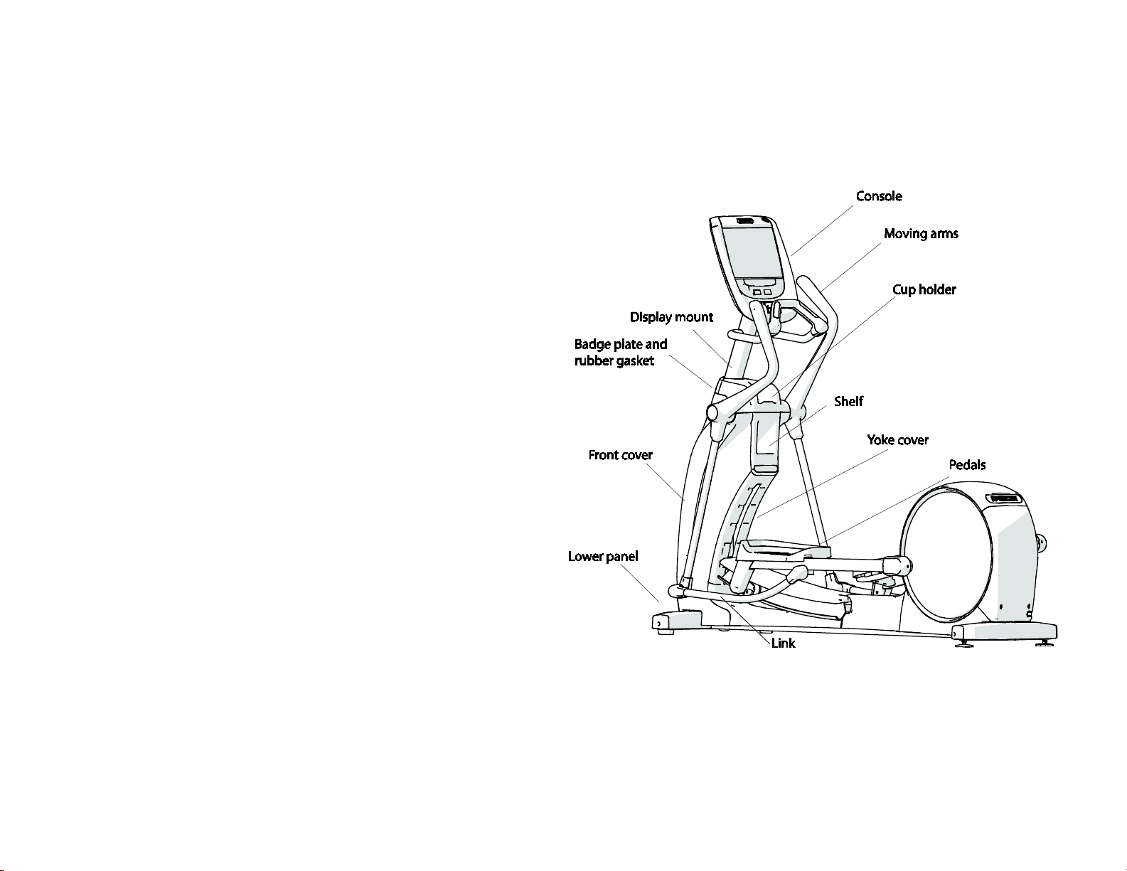
Page 4

1
Experience™ Series 800 Line
Elliptical Fitness Crosstrainer™ (EFX)
Assembly Guide
Equation 1: English
Page 5
3
800 Line EFX® Assembly Guide
WARNING
At least two people are required to assemble the equipment. DO
NOT attempt assembly by yourself.
Follow the steps in the order listed in this assembly guide. For more product
information, visit us at www.precor.com.
Assembly requirements
Important Before you fully tighten a fastener, check that its head is flush with the
surface of the equipment. If not, cross-threading may have occurred. DO NOT attempt
to rework the assembly as more damage to the equipment will occur. Instead, contact
Customer Support at www.precor.com
We recommend you:
• Assemble the equipment close to where you plan to use it.
• Assemble the equipment on a solid, flat surface, so that it remains level
and stable.
• Locate the equipment at least 19.7 inches (0.5 meter) away from walls or
furniture on either side of the equipment, and 19.7 inches (0.5 meter)
away from objects behind or in front of the equipment.
• DO NOT move the equipment without assistance.
Torque measurements
• Display bolts 180 in-lbs (20 N-m)
• Links 300 in-lbs (34 N-m)
• Set screws 300 in-lbs (34 N-m)
• Plastite screws 20 in-lbs (3.4 N-m)
Fig
ure 1
Page 6
4
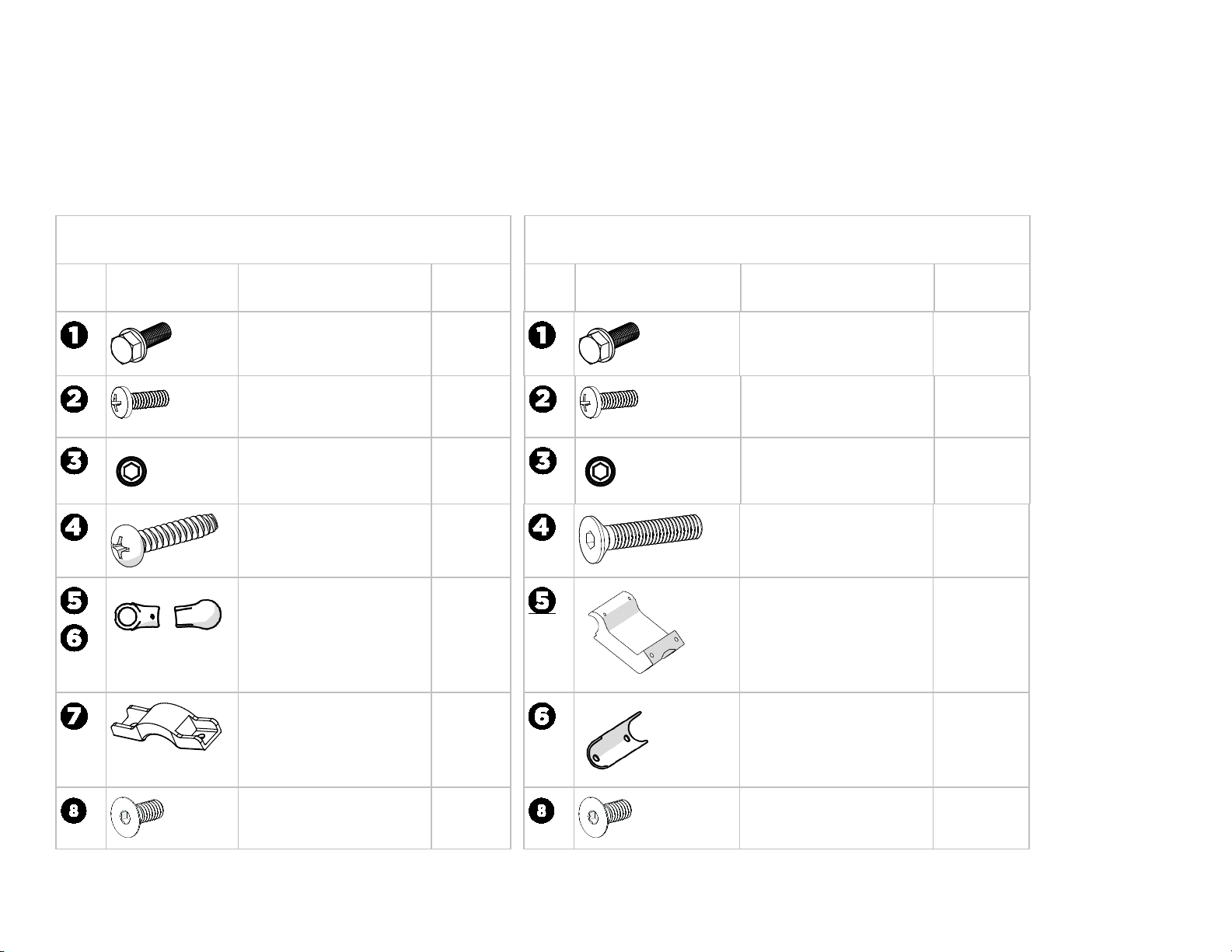
Tools and Hardware
3/16-inch Allen wrench
9/16-inch hex wrench (or socket)
#2 Phillips screwdriver
1/2-inch hex wrench (or socket
7/16-inch open-end wrench
Tape
Moving Arms Hardware Kit
Fixed Arms Hardware Kit
Component
Description
Quantity
Component
Description
Quantity
16-18 x 1-inch
5/
Sems bolt
4 x 3/4-inch Phillips self-
1/
tapping screw
3/
8-16 set screw 2, plus 2
#
8 Plastite screw
1/4-20 x 1 1/2-inch
I
nner and outer
link covers
ide panel anchor
S
(used in both Moving and
Fixed Arms)
4
18
extra
2
Set of 2
2
16-18 x 1-inch
5/
Sems bolt
/4 x 3/4-inch Phillips self-
1
tapping screw
8-16 set screw 2, plus 2
3/
4-20 x 1 3/4 long
1/
flathead screw
Fi
xed arm bracket 1
Fi
xed arm cover 1
4
20
extra
4
1/
4-20 x 3/4-inch flathead
screw
4, plus 1
extra
4-20 x 3/4-inch flathead
1/
screw
2, plus 1
extra
Page 7
5
Begin assembly
this procedure, retrieve the electrical and communication cables for
DANGER DO NOT attempt to connect electrical power until all assembly procedures are complete and the console is properly installed.
To install the console mount:
Before you begin
the console that you plan to install on this EFX. These cables are shipped with the
console.
1. Position the display mount on top of the base frame and attach it using the four
bolts (see Figure 2). Fully tighten all bolts (torque=180 in-lbs, 20 N-m).
Figure 2
2. For touchscreen consoles: Group all four cables--communication, coax, power
extension supply, and Ethernet--and thread them upward through the center
column and out through the center opening in the console mount. Tape it to the
top of the console mount to secure it temporarily.
Note For non-touchscreen consoles,the communication cable is pre-threaded.
Important DO NOT stretch, crimp, or damage the cable.
Cables damaged by improper installation will not be covered by the Precor Limite
arranty.
W
d
Page 8

6
To install side panels:
1. Secure each side panel using four self-tapping screws
2. Make sure to fully tighten fasteners (torque = 35 in-lbs,
for each panel.
3.95 n-M.)
Figur
e 3
Page 9
7
WARNING DO NOT allow cables to touch any moving parts around the lift motor body—lift screw, yoke, or ramp. Run
the ramp through its movement path a few times and have someone else watch to make sure no cables are
caught up or hanging loosely.
Depending on the site location and distance from an outlet, you might need to route the power supply either internally (below) or externally (see page 8).
To route the power supply internally:
1. Hook the Power Supply Bracket* onto the right upright
(see Figure 4a).
* Included only in touchscreen console boxes
2. Coil up all cables—coax, power extension , and Ethernet—and hold
the power supply on the holder with one hand, and with the other
hand, thread a large zip tie around the upright support (see Figure 4b).
Note Make sure you thread the zip tie through the designated slots
in the power supply bracket .
3. Pull the zip tie tight only after you have reduced any slack by pulling
the cables tighter from the top.
4. Insert the grounding jumper in to the ground connector, and then
secure the cables inside each of the three cable clips attached to the
right upright support. Leave cable connectors loose until after the
lower panel is installed (see page 9).
support
Figu
re 4a
To complete the console installation, refer to the installation guide shipped with your console.
Figu
re 4b
Page 10

8
WARNING DO NOT allow cables to touch any moving parts around the lift motor body—lift screw, yoke, or ramp.
Run the ramp through its movement path a few times and have someone else watch to make sure no cables are caught up or
hanging loosely.
To route the power supply externally:
1. Coil up all cables—coax, power extension , and Ethernet—and hold them
in place with one hand, and with the other hand, thread a large zip tie around
the upright support (see Figure 5).
Note Make sure you thread the zip tie through the designated slots in the
power supply bracket .
2. Pull the zip tie tight, making sure you have enough slack in the power and
extension cable.
3. Insert the grounding jumper in to the ground connector, and then secure the
cables inside each of the three cable clips attached to the right upright
support. Leave cable connectors loose until after the lower panel is installed
(see To install lower panel and front cover).
To complete the console installation, refer to the installation guide shipped with your console.
Figu
re 5
Page 11

9
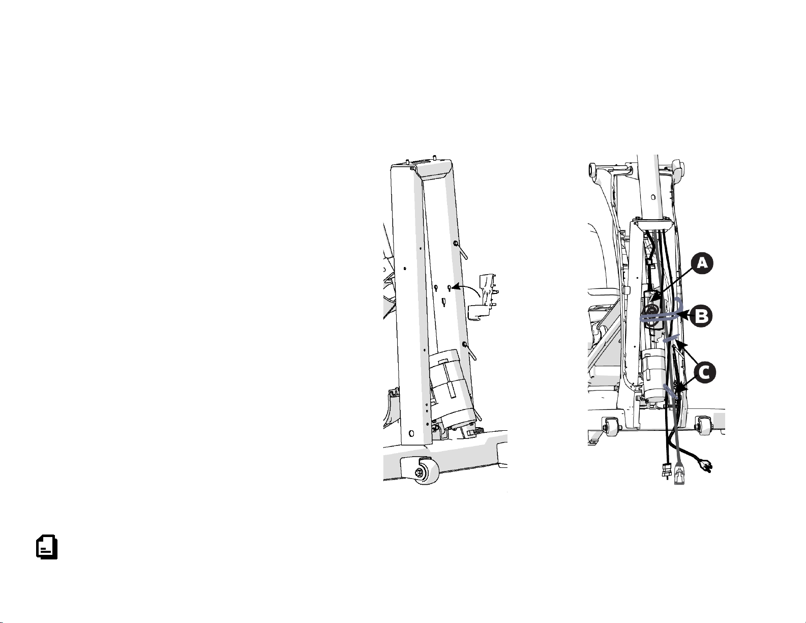
To install lower frame cover:
1. Lift up the lower frame cover, about an inch from the frame.
Figure 6a Insert screws for lower frame
2. Install lower frame
3. Press the side panels in place, ensuring the latches under the
arrows on each panel are secured.
Notes
• Make sure cables don't catch on latch of forward frame cover
(see Figure 6b) and are tied to the outside and away from the
screw (see Figure 6c).
screws (see Figure 6a).
re 6b Close up to show detail
Figu
• Make sure the clips on the lower frame cover hook
over the clips on the right and left side panels
(see Figure 6b). Use finesse not force to secure the parts
together with no gap between them.
Figure 6c Correct and incorrect cable placement
Page 12

10
To install lower panel and front cover:
1. Position the cover plate into the center opening of the lower panel.
2. Install the coax coupler, star washer, and nut, into the jack plate on the lower panel and tighten (see Figure 7).
3. C
onnect the coax cable to the inside end of the coax coupler . Tighten the connector using a 7/16-inch open-end wrench.
Note Check the bend radius (about 6 inches) on the coax cable so that it is at a natural angle.
4. Attach the Ethernet coupler
5. Attach the lower panel using two screws, routing the power cable through designated far right slot. Fully tighten fasteners on the panel.
into the jack plate on the lower panel (see Figure 7) and plug the
re 7
Figu
Fi
gures 8 and 9
Ethernet cable into the coupler.
Page 13

11
To install yoke cover and shelf:
1. Attach the yoke cover to the back of the base mount using two screws (see Figure 10). Note Make sure the small latches engage with the side covers.
2. Fully tighten fasteners (torque for = 300 in-lbs, 34 N-m).
3. Position the shelf in to the tabs near the top of the yoke cover then, secure the anchors over the bar using two screws .
Fig
ure 10
4. Push the front cover onto the front of the base mount all the way in, and with your fingers, press the arrows on either side of the cover (see Figure 11).
Fig
ure 11
Page 14

12
To install moving arms:
1. Insert the shaft of the moving arm to the center mount and align pre-installed set
sc
rews to the shaft (see Figure 12). Fully tighten all screws, including pre-
installed ones (torque = 300 in-lbs, 34 N-m).
ure 12
Fig
2. Attach the link to the moving arm using the 9/16-inch socket wrench
on the pre-installed bolts.
Note Make sure to place the inner cover between parts before bolting the
components together.
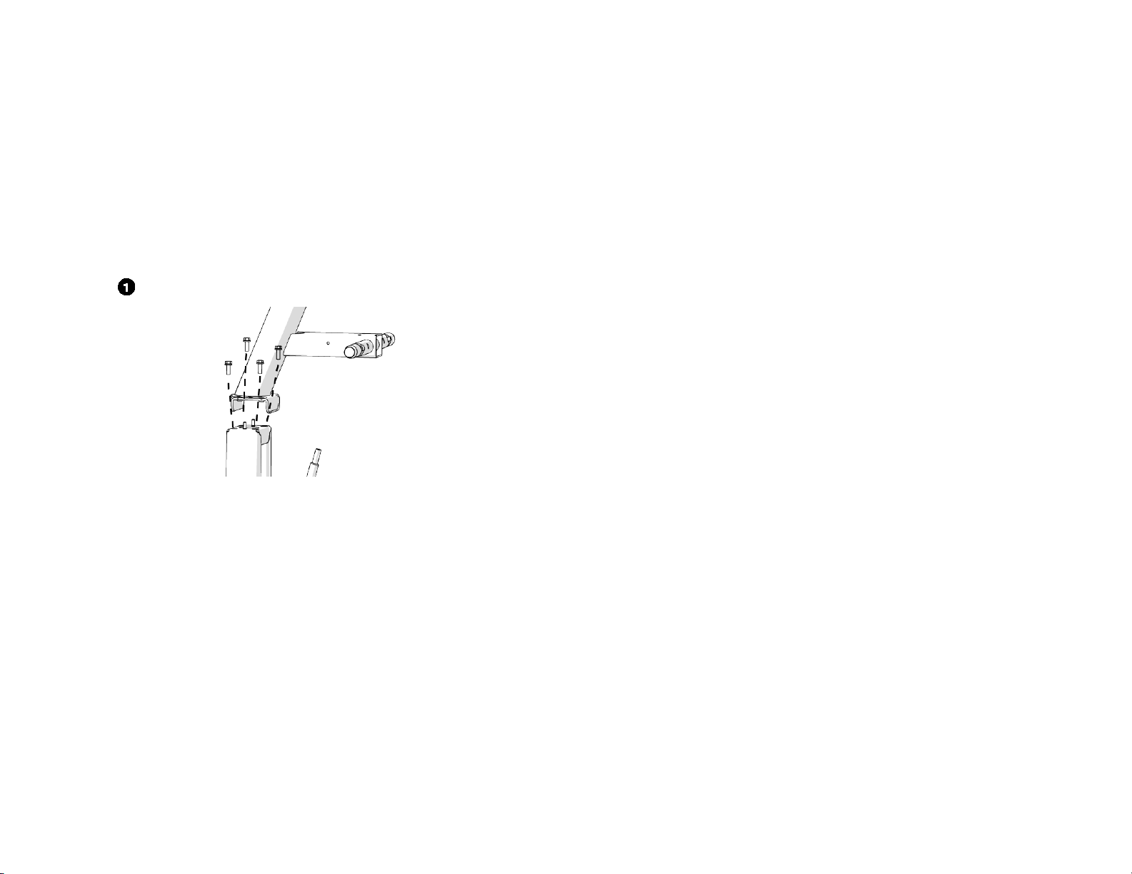
To install fixed arms:
1. Install the console. For instructions, refer to the console guide included in
the console box.
2. Install two Plastite screws into the upper display (see Figure 13).
3. Insert the shaft of the arm to the center mount using two set screws .
Partially tighten mounting fasteners.
4. Rotate arm assembly up and attach clamp using two self-tapping screws
.
5. Fully tighten all fasteners (torque for 2 and 3 = 300 in-lbs, 34 N-m an
tor
que for 4 =20 in-lbs, 3.4 N-m).
d
3. Attach the outer link covers using two Plastite screws (torque for 4= 20
in-lbs, 3.4 N-m.).
Fig
ure 13
Page 15

13
To attach the cup holder:
1. Position the cup holder on top of the lower shelf, making sure to catch the
bottom latch in the shelf component (see Figure 14).
re 14
Figu
2. Position your hands on the arrows and press down at the top of the panel.
To complete the installation:
1. Position the badge plate on the front cover and press into place (see Figure 15).
re 15
Figu
2. Wrap the rubber gasket on top of the badge plate from the back of the display
mount so the split is pointed toward the front. Press down to snap in two tabs at
the back, then walk your hands around wiggling and aligning the remaining tabs
as you go.
3. Refer to the corresponding Console Installation Guide found (in the console box)
to attach your console.
4. Plug in the power cord.
Page 16

800 Line EFX® Ass
©2016 Precor Incorporated | October 2016
embly Guide | P/N 304293-101 rev C, ENU
Page 17

Cardio Equipment Quick Reference
Maintenance Guide
Page 18

Cardio Equipment Quick Reference Maintenance Guide
complete
Important
Weekly Maintenance Tasks
DO NOT lift and hold equipment while vacuuming.
Keep excess moisture away from electronic components to prevent electrical shock or damage, and
dry completely.
For elliptical and treadmill only
Elliptical only
Treadmill only
For
to www.precor.com for more information.
maintenance and cleaning information, visit us at www.precor.com. For torque settings, review the product Assembly Guide included with your equipment, or go
The owner is responsible for maintaining Precor equipment in their facility based on the recommendations below and any accompanying material.
Cleaning procedures
Use a lint-free cloth dampened with water or an approved cleaner in the procedures below.
• Clean the floor under the equipment.
When the floor is completely dry, restore power and return the
equipment to its level position.
• Clean all surfaces of the frame and plastic components.
• Use a soft nylon scrub brush to clean grooves and textured surfaces on foot contact locations.
• On LCD- or PVS- equipped equipment, clean the screen using only a diluted solution of one part 91% isopropyl alcohol to one part water on a damped, lint-free cloth.
Dry completely.
•
Other weekly maintenance tasks for all equipment
• Unplug the power cords from any equipment or entertainment devices plugged into a wall outlet. For treadmill: Turn off the circuit breaker.
• Verify all equipment feet sit squarely on the floor, and adjust if necessary to ensure the equipment does not wobble.
• Verify that the power cords are not damaged or pinched.
• Plug in the equipment, turn it on, and verify the following features are performing properly:
Handheld Heart Rate (HHHR)
Incline, Speed, and Resistance controls
•
Elevate the equipment to its maximum incline.
Clean the ramp (no disassembly required). Debris build-up will shorten the life of the product.
•
Verify the safety lanyard works.
Emergency Stop Button
Elevate the equipment to its maximum incline.
Follow the procedures, Check the alignment of the running belt and Adjust the running belt, in this Guide.
Clean debris from all wheels (for treadmill and elliptical) and CrossRamp® (for elliptical). Dry completely.
4
Page 19

Monthly Maintenance Tasks
Treadmill, elliptical, and AMT only
Treadmill only
Treadmill only
Elliptical only
AMT and climber only
All equipment except treadmill
Bikes only
For treadmill only
Perform all checks listed under Weekly Maintenance Tasks plus the following:
For all equipment
• Verify the Wireless Heart Rate feature is performing properly by following the procedure, Verify that the heart rate feature works, in this Guide.
• Remove plastic enclosures from the drive compartments and remove any lint or debris, and then do the following in order:
Clean the drive belts and pulleys with a small wire brush.
Vacuum out any debris, being careful not to bring the vacuum cleaner nozzle too close to any circuit board. Precor recommends you use a vacuum that protects
against static buildup.
Inspect visible welds, frame, and wire connections.
Check all fasteners for proper tightness and torque.
Clean and lubricate the lift motor screw with an approved grease such as SuperLube® with Teflon or Mobil 1™ synthetic
grease, if necessary.
Replace all removed plastic enclosures.
•
•
Verify that the wheels run smoothly on the CrossRamp®.
Check all wheels for wear or cracks.
Lift the badge plate from the bottom front to loosen the rubber gasket. Remove the gasket (at the split) from the back of the display mount. Clean debris then
Verify the power cord clamp is securely installed.
Visually inspect the running deck and belt. Make sure the deck and belt are in good condition and replace the belt, if necessary.
replace the gasket from back to front, aligning the tabs as you go.
DO NOT pull the gasket ring off before removing the badge plate first.
•
•
•
•
Verify that the seat moves through the entire adjustment range and that the position latch works correctly.
Inspect support belts and pulleys for wear or damage. Check torque on belt clamps.
Verify pedals move smoothly and freely in all directions.
Clean the underside of the running belt and top deck by following the procedure, Clean the running belt and deck in this Guide or visit us at
www.precor.com.
5
Page 20

Quarterly Maintenance Tasks
AMT only
EFX only
Bikes only
Climber only
Semi-Annual Tasks
All equipment except treadmill
Treadmill only
Perform all checks listed under Weekly Maintenance Tasks and Monthly Maintenance Tasks, plus the following:
• Check tension of the running belts and adjust if necessary. Inspect belts for excessive wear.
• Perform software diagnostics and check LED function.
•
•
•
•
Inspect the gas spring shock. Contact Precor Customer Support if you have questions.
Check the belt tension.
Verify that the seat is secure and stable.
Inspect the tension springs and pedal stops for damage and function.
•
•
Lubricate the lift motor screw.
Verify battery voltage.
6
Page 21

Error Codes
Error Codes
Action
Equipment
The following is a list of error codes and how to resolve the issue:
Turn t
00-09, 11-16, 50
10, 20-23, 26-28, 32, LS, ERR, E2,
E4
40, 42, 44-46 Logs error and displays code to user. User can continue the workout without interruption. AMT, elliptical, treadmill, RBK, UBK, and CLM
80-83
30, 31
62, 70-77 Contact a Precor certified service technician. AMT only
he equipment off and on. Repeat twice. If the message still appears, contact a Precor certified
service technician.
Contact a Precor-certified service technician. AMT, elliptical, treadmill, RBK, UBK, and CLM
Turn t
he equipment off and on. Repeat twice. If the message still appears, contact a Precor certified
service technician.
Displays the error on the console to the user. Restart the equipment or reset the E-STOP to use. Logs as a
fatal error.
AMT, elliptical, treadmill, RBK, UBK, and CLM
AMT, elliptical, treadmill, RBK, UBK, and CLM
AMT, elliptical, treadmill, RBK, UBK, and CLM
78
79
17-20, 25, 85-88
29
33, 35-37, 60, 62
Display the message, "Belts must be changed soon", in place of the standard banner text. Logs the error
and allows the user to begin the workout. Contact a Precor certified service technician.
Displays the message, "Belts change required", in place of the standard banner text. No workout can be
started. Contact a Precor-certified service technician.
Turn t
he equipment off and on. Repeat twice. If the message still appears, contact a Precor certified
service technician.
Displays the error on the console to the user and pauses the workout. The treadmill speed MUST return
to 0 before starting again. Logs the error.
Displays the error on the console to the user. Restart the equipment or reset the E-STOP to use. Logs as a
fatal error.
AMT only
AMT only
treadmill only
treadmill only
treadmill only
7
Page 22

Verify that the heart rate display works
To verify that the heart rate display is operational:
Moving the equipment
To move the elliptical (EFX):
To move the AMT:
To move the treadmill:
1. Begin exercising on the equipment and grasp both touch-sensitive handlebars. The heart icon flashes while the heart rate is read. You must maintain contact with both
metal plates on each handlebar to ensure an accurate reading.
2. Within ten seconds, your heart rate number appears in the HEART RATE display. If a number does not appear, perform the following checks:
Verify that the HR cable is properly connected.
Repeat the test with a different person. In rare instances, it may not work properly for a few individuals.
Repeat this test using a chest strap or a wireless pulse simulator. You’ll get better results than if you only grasp the touch-sensitive handlebars. DO NOT hold
onto the handlebars during the reading or you’ll override those results.
The equipment is very heavy. If you plan to move it to a new location, obtain the help of an adult assistant and use proper lifting techniques. If the equipment includes roller
wheels on one end, use the wheels to reduce the load on yourself and your assistant.
• Precor recommends using a four-wheeled dolly to move the EFX.
1. Disconnect, unplug, and remove all external connections (television, Ethernet, and power).
2. Lift the rear platform molding to remove it.
3. Lift the rear foot supports to tip the AMT forward onto its roller wheels.
4. Push the AMT into its new location.
5. Lower the rear foot supports to the floor, then reattach the rear platform molding.
A treadmill in an inclined position is easier to move.
Important
The plastic end caps on Precor treadmills are designed specifically for lifting. Working with your assistant, place a hand under each side of the end cap. Then,
using proper lifting techniques, lift the rear of the treadmill so that it rolls on its front wheels.
8
Page 23

To put the treadmill into an inclined position for moving:
GO
Check the alignment of the running belt (treadmill only)
Important
1. Press
2. Increase the incline to Level 4 or more.
3. While the treadmill is running, turn the main power switch to OFF.
4. Disconnect the treadmill’s power cord.
on the console.
Failure to align the belt may cause the belt to tear or fray, which is not covered by the Precor Limited Warranty.
Proper alignment allows the belt to remain centered and ensures smooth operation. Realigning the belt takes a few simple adjustments. If you are unsure about this
procedure, contact Precor Customer Support.
CAUTION DO NOT adjust the running belt when someone is standing on it.
To check the alignment of the running belt:
1. Make sure that the running surface is as level as possible. If necessary, adjust the rear feet to level the treadmill.
Adjusting the rear feet cannot compensate for extremely uneven surfaces. If you cannot make the running surface level and stable, move the treadmill.
Note
2. Turn the treadmill on.
3. Stand beside the treadmill (not on it), and press GO or QuickStart on the console.
4. If necessary, enter the safety code by pressing the number keys in sequence. The running belt starts automatically after a 3-second countdown appears on the console.
5. Press SPEED UP until the console shows a speed of 3 mph (5 kph).
6. Observe the belt from the rear of the treadmill for a few minutes. The belt should remain centered along the running bed. If it drifts off center, you need to adjustment it.
CAUTION If you hear any rubbing or the running belt appears damaged, press the red STOP button immediately and contact Precor Customer Support.
7. Press STOP to stop the belt and turn the treadmill off.
9
Page 24

Adjust the running belt (treadmill only)
CAUTION
Take special care when aligning the running belt. The treadmill will not stop immediately if an object becomes caught
in the belt or rollers. Turn OFF the treadmill while adjusting or working near the rear roller. DO NOT wear loose
clothing or allow your hair to hang loose during this procedure. DO NOT adjust the running belt when someone is
standing on it. Keep your fingers and any other object clear of the belt and rollers, especially in front of the roller and
behind the deck.
Important
To adjust the running belt:
Figure 1
If the belt ...
Then ...
Note
If you are unsure about adjusting the running belt, contact Precor Customer Support.
Make all belt adjustments on the adjusting bolts at the rear corners of the treadmill using the hex key provided, and DO NOT turn either bolt more than
¼ turn before checking the alignment of the running belt again. Overtightening the adjusting bolts can damage the treadmill.
1. Locate the adjusting bolt in the right side end cap at the rear corner of the treadmill
(Figure 1).
2. Use the hex key to tighten the adjusting bolt in the direction that the belt is shifting.
Turn the bolt ¼ turn clockwise.
Continues to shift in the original
direction
Starts to shift in the opposite
direction
3. Re
check the belt position as described in Check the Alignment of the running belt.
If the belt slips after you have adjusted it, tighten the adjusting bolt evenly, ¼ turn at a time, until the slipping stops. DO NOT overtighten the belt.
Turn the same adjusting bolt an
additional ¼ turn clockwise.
Turn the same adjusting bolt ⅛
turn or less counterclockwise.
10
Page 25

Clean the running belt and deck (treadmill only)
CAUTION
DO NOT stand or allow others to stand on the treadmill running belt during this procedure.
To make sure the safety stop key works:
To clean the treadmill belt and deck:
Figure 2
Before you begin the cleaning procedure, check that the safety stop key works correctly.
1. Stand to one side of the treadmill.
2. Make sure that the stop key lanyard is hanging straight down and is not wrapped around the handle bars.
3. Press QuickStart and wait for the running belt to begin moving.
4. Press the safety stop key.
5. The running belt should stop immediately. When it stops, reset the safety stop key.
CAUTION If the running belt does not stop, turn off the treadmill power using the On/Off switch at the front of the treadmill and unplug the
power cord. The treadmill must remain out of service until the stop switch is repaired. Place an "out of order" sign on the treadmill
and contact Precor Customer Support.
6. Turn the treadmill power switch to Off. The On/Off switch is located at the front of the treadmill.
1. Make sure the treadmill is turned off.
2. Take a clean, dry cotton towel that is at least 36 in. (2 m) long and fold it in half
lengthwise.
3. Lift the r
inches of towel extend over the deck trim on each side.
4. Push the t
safety stop key.
5.
Turn the power switch to On.
6. Step on
to your clothes.
Important
7. Stand firmly on both ends of th
unning belt up and push the towel under the belt. Make sure a few
owel forward to the front of the machine so it is located beneath the
to machine by standing on the side rails and attach the stop key lanyard
DO NOT stand on the running belt at any time.
e towel keeping your feet off of the treadmill running belt (Figure 2). Brace yourself using the handlebars or side hand rails.
11
Page 26

8. Press Quick Start.
DO NOT adjust the treadmill’s speed or run it higher than 1 mph.
Important
You have three seconds before the treadmill belt begins to move. Hold the handlebars or side hand rails to help maintain balance.
9. The treadmill will run at 1 mph. Allow the treadmill to run for one minute while keeping the towel firmly in place.
CAUTION
Press the safety stop key if the towel becomes loose to prevent it from being pulled into the treadmill’s rollers.
10. After one minute, press Stop to stop the treadmill belt.
11. When the belt is completely stopped, remove the stop key lanyard from your clothing, and step off the treadmill.
12. Turn the treadmill power switch to Off.
13. Grasp both sides of the towel and run it up and down the length of the belt several times to clean the top of the deck before removing it from beneath the belt.
14. Turn the power switch to On and return the treadmill to normal use.
Maintenance Guide | P/N 305034-101 rev A, ENU
©2016 Precor Incorporated | April 2016
12
Page 27

Page 28

Page 29

Page 30

Page 31

Page 32

Page 33

Page 34

 Loading...