

Page 1

Electronic
Console
with the
Pulse Feature
R
USA
Owner’s Manual
Assembly and Operation
page 1
Page 2

Safety Information
Please review and observe the following safety guidelines when
assembling and using the Precor 903/904 electronic console:
Before beginning any fitness program, you should see your
physician for a thorough physical examination.
• Read the Owner’s Manual and follow all instructions.
These instructions are written to ensure your safety
and to protect the equipment.
• Handle the Precor 903/904 electronic console with
care. Do not drop the equipment. It might damage the
device and you could void the Precor limited warranty.
• After extensive use, the batteries may wear out which
causes the information on the display to flicker
erratically or not appear at all. If you need to replace
the batteries, refer to
maintenance section of this manual.
• Do not operate the treadmill for a 24-hour period after
installing the magnet and reed switch. A 24-hour
period is required so that the adhesive on the
mounting pads can bond properly.
The Precor 903/904 electronic console is designed to
enhance your workout. By following the above precautions
and using good common sense, you will have many safe
and enjoyable hours of healthy exercise with your Precor
products.
Replacing the Batteries
in the
page 2
Obtaining Service
Do not attempt to service the 903/904 electronic console
yourself other than assembling the magnet and reed switch
and maintaining the electronic console as discussed in this
manual.
For information about product operation or service, contact
an authorized Precor dealer (or a Precor Factory Authorized
Service Company). To locate the Precor dealer or service
company nearest you, call 1-800-4-PRECOR.
Page 3

Table of Contents
Safety Information ........................................................... 2
Obtaining Service ........................................................ 2
Before You Begin.......................................................... 4
Unpacking the Electronic Console ................................ 4
Installing the Electronic Console ................................. 5
903 Assembly Procedures........................................... 5
904 Assembly Procedures........................................... 9
Installing the Mounting Pads ....................................... 12
Attaching the Magnet and Reed Switch ....................... 14
Using the Electronic Console ....................................... 17
Electronic Console Buttons.......................................... 17
Electronic Console Displays......................................... 18
Setting the Timer ......................................................... 19
Setting the Distance..................................................... 20
Choosing a Target Heart Rate ...................................... 20
Resetting Your W orkout Statistics .................................... 22
Maintaining the Electronic Console .................................... 23
Replacing the Batteries................................................ 23
Appendix A — Flywheel Template ............................... 26
page 3
Page 4

Before You Begin
Thank you for purchasing the easy-to-use electronic
console option for your Precor 903 Manual or 904 Total Body
Treadmill. Before assembling the console onto your
treadmill, take the time to read through this manual so that
you are familiar with the contents of the package and the
features on the electronic console.
Obtain the appropriate tools before assembling the electronic
console onto the 903 or 904 treadmill. You will need a Phillips
head screwdriver to attach the electronic console onto the
handrail clamp.
Unpacking the Electronic Console
Carefully unpack the electronic console and its components.
Make sure that you have the following items:
❑ one electronic console
❑ one mounting bracket with four (two short and two
long) Phillips head screws
❑ one reed switch and wire
❑ one magnet
❑ one ear clip and wire connector
page 4
❑ three C clips—holds reed switch wire to handrail
❑ two mounting pads (one thick and one thin pad)
If any items are missing, contact the dealer from whom you
purchased the treadmill or call 1-800-4-PRECOR for the dealer
nearest you.
Page 5
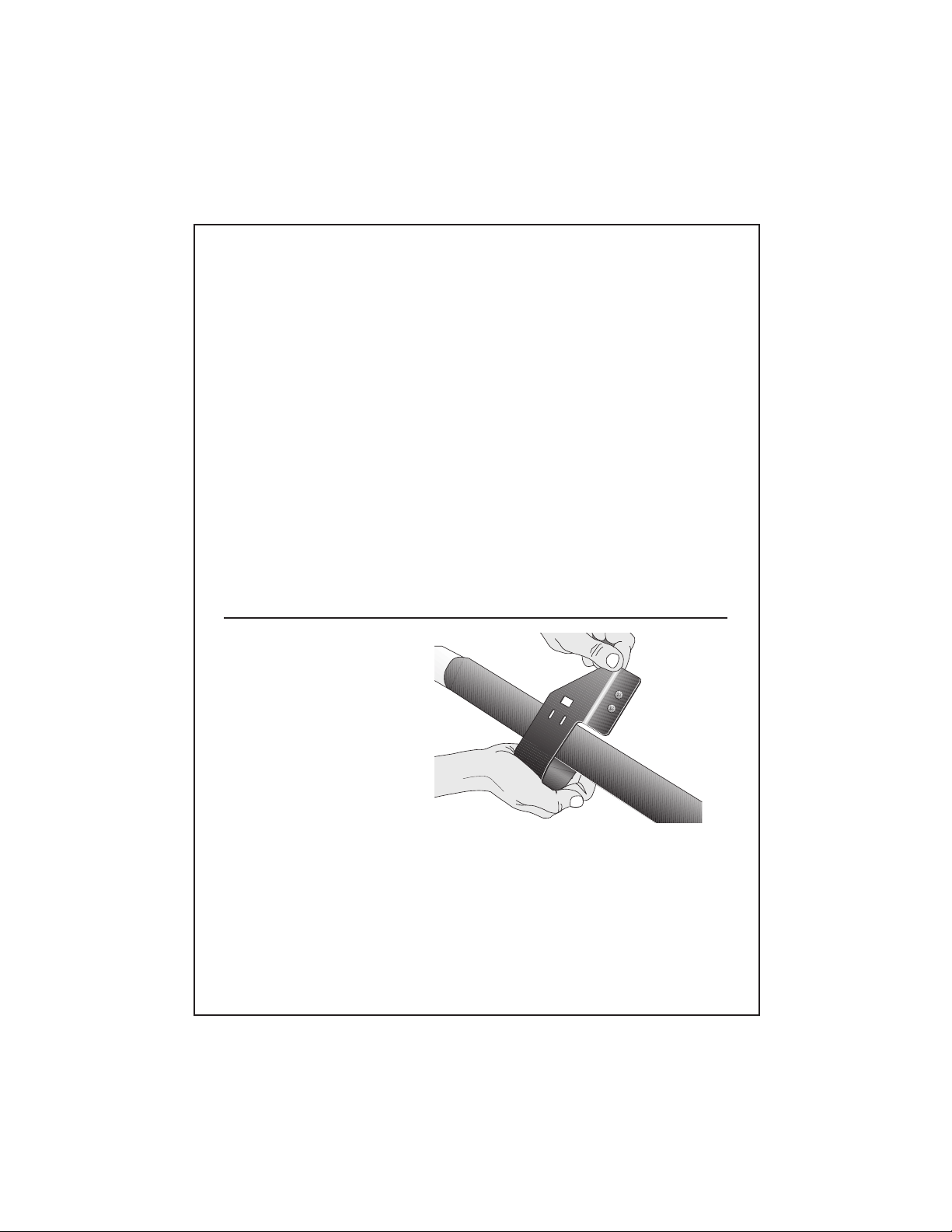
Diagram 1
Installing the Electronic Console
The handrail clamp can be used on either the 903 or 904
treadmill. However, the steps used to install the console
onto the clamp are slightly different depending on which
treadmill you have. Please refer to the steps that apply to
your treadmill.
903 Assembly Procedures
To install the 903 electronic console, take the following
steps:
1. Locate the handrail clamp in the box that accompanies the
electronic console’s box. Remove the long and short
screws from the handrail clamp using your fingers or a
Phillips head screwdriver. Set the screws aside. You can
discard the short screws since they are only used for the
904 assembly.
2. Place the handrail clamp around the mid-portion of the
handrail as shown in Diagram 1. Place a hand on
either side of the handrail clamp to gently pull it apart
so that you can slide it onto the handrail’s foam grip.
Important: Do not mount the clamp on the painted surface
of the handrails.
page 5
Page 6
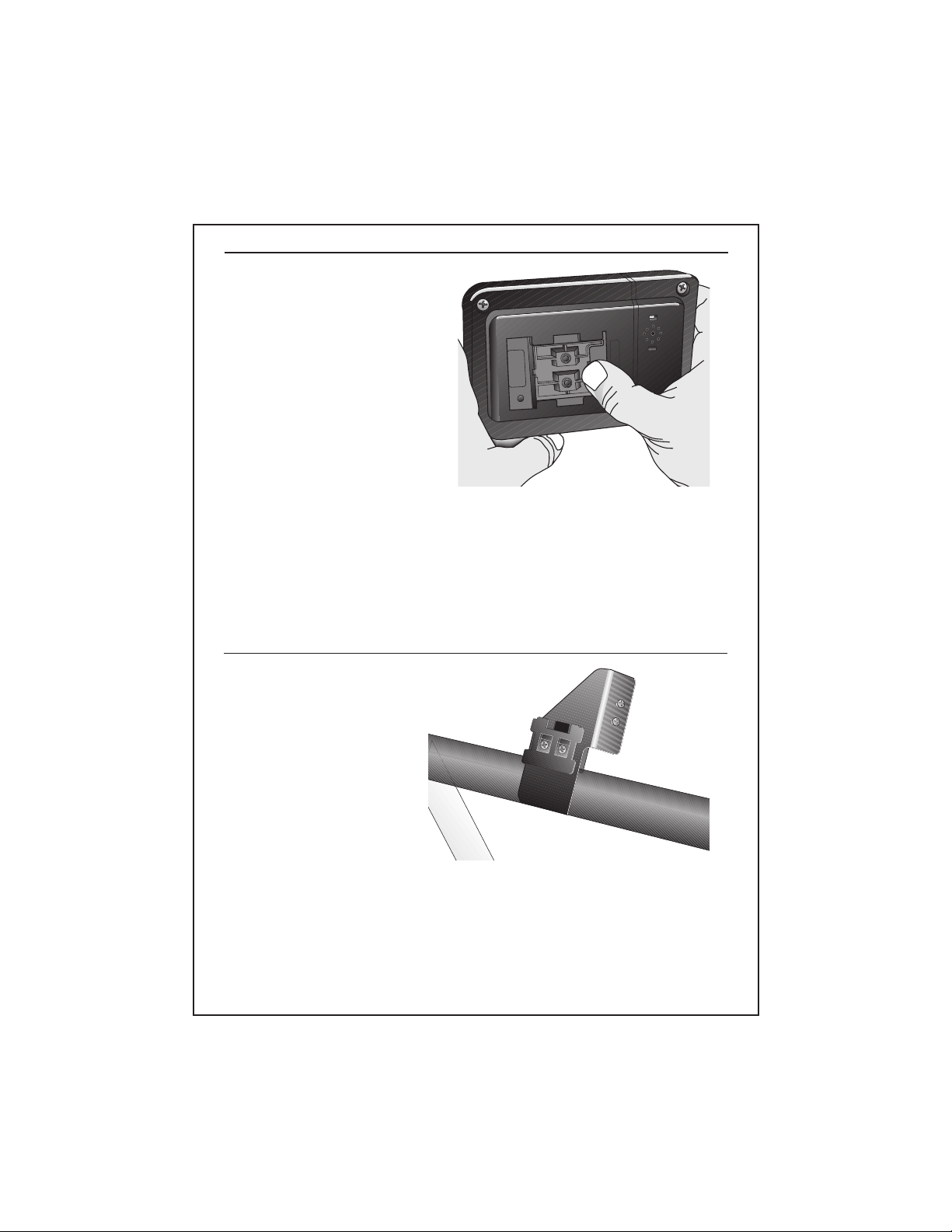
Diagram 2
Diagram 3
3. Unlock and remove the mounting bracket from the back of
the electronic console. Unlock the mounting bracket by
pushing it down toward the base of the console. See
Diagram 2.
page 6
4. Position the mounting bracket onto the handrail clamp so
that the smooth side of the plate is facing you. See
Diagram 3.
Page 7
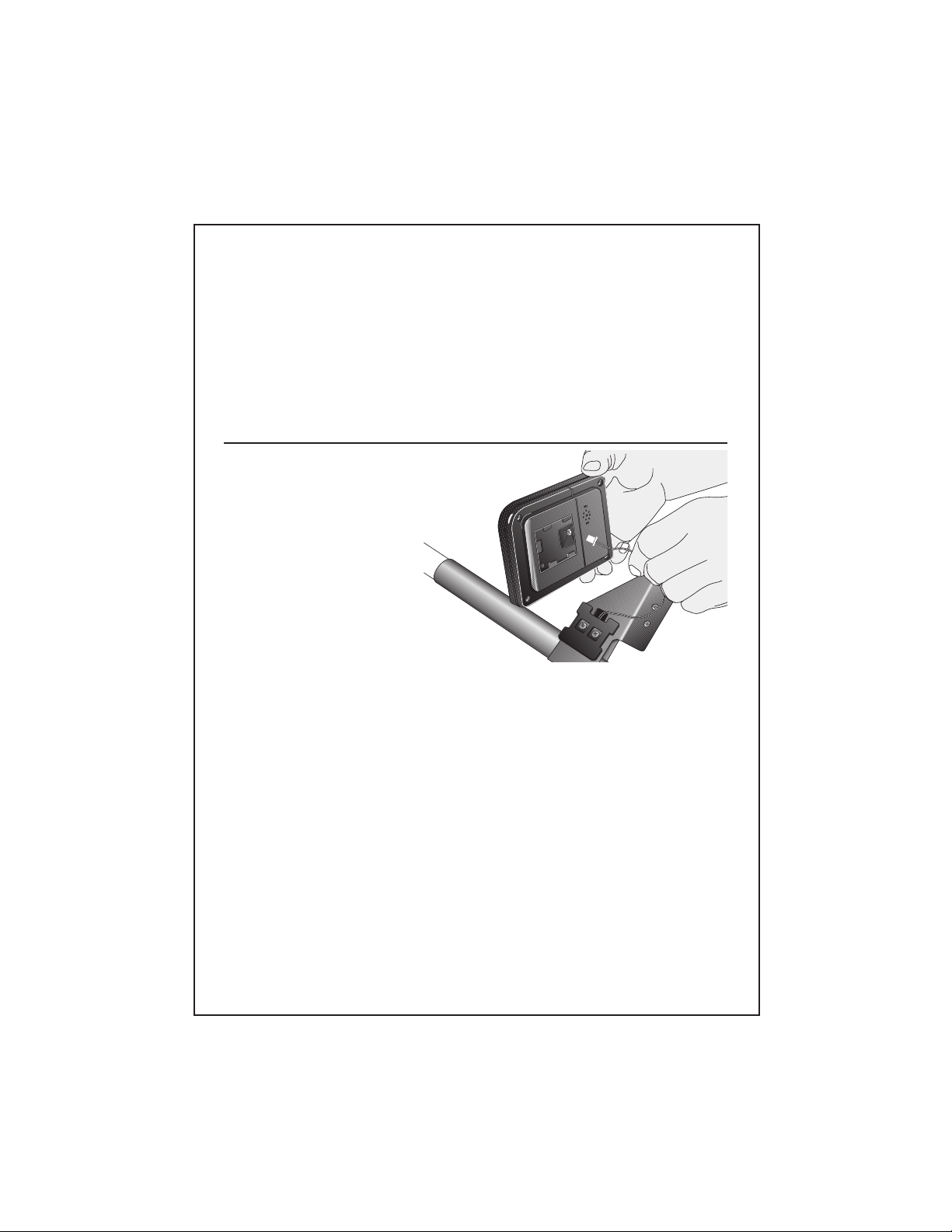
Diagram 4
5. Secure the mounting bracket and clamp by inserting the
two long screws through the mounting holes. You may
need to squeeze the ends of the clamp together to install
the screws. See Diagram 3. Tighten the screws into the
recessed holes on the mounting plate using the Phillips
head screwdriver. Do not over tighten the screws. A gap
should remain between the opposite sides of the handrail
clamp.
6. Unwrap the reed switch wire. Route the connector and
wire through the hole in the handrail clamp. See
Diagram 4.
7. Plug the connector into the receptacle as shown in
Diagram 4. Do not force the connection. The
connector is designed to engage in one direction only.
A tab on the connector and a slot on the receptacle
help you determine the proper alignment.
8. Align the back of the console with the mounting
bracket and slide the electronic console onto it. Gently
pull the excess wire through the hole in the handrail
clamp while you slide the console toward the rear of
the treadmill.
page 7
Page 8
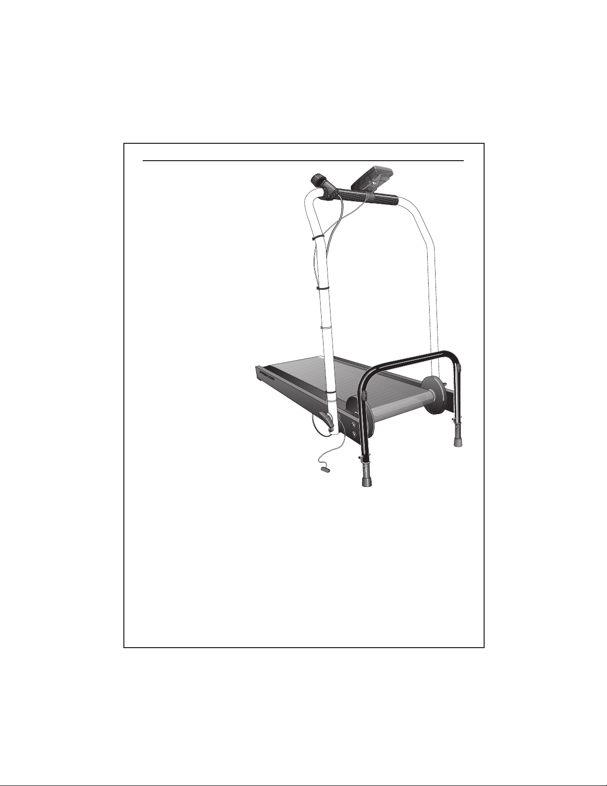
Diagram 5
903
R
USA
page 8
9. Attach the C clips around the handrail as shown in
Diagram 5. Position the slight protrusion on the C clip
around the reed switch wire and micro-adjustment knob
cable. Squeeze the C clips together to close them and
secure the wires in place.
10. With the electronic console successfully mounted, continue
to
Installing the Mounting Pads
.
Page 9
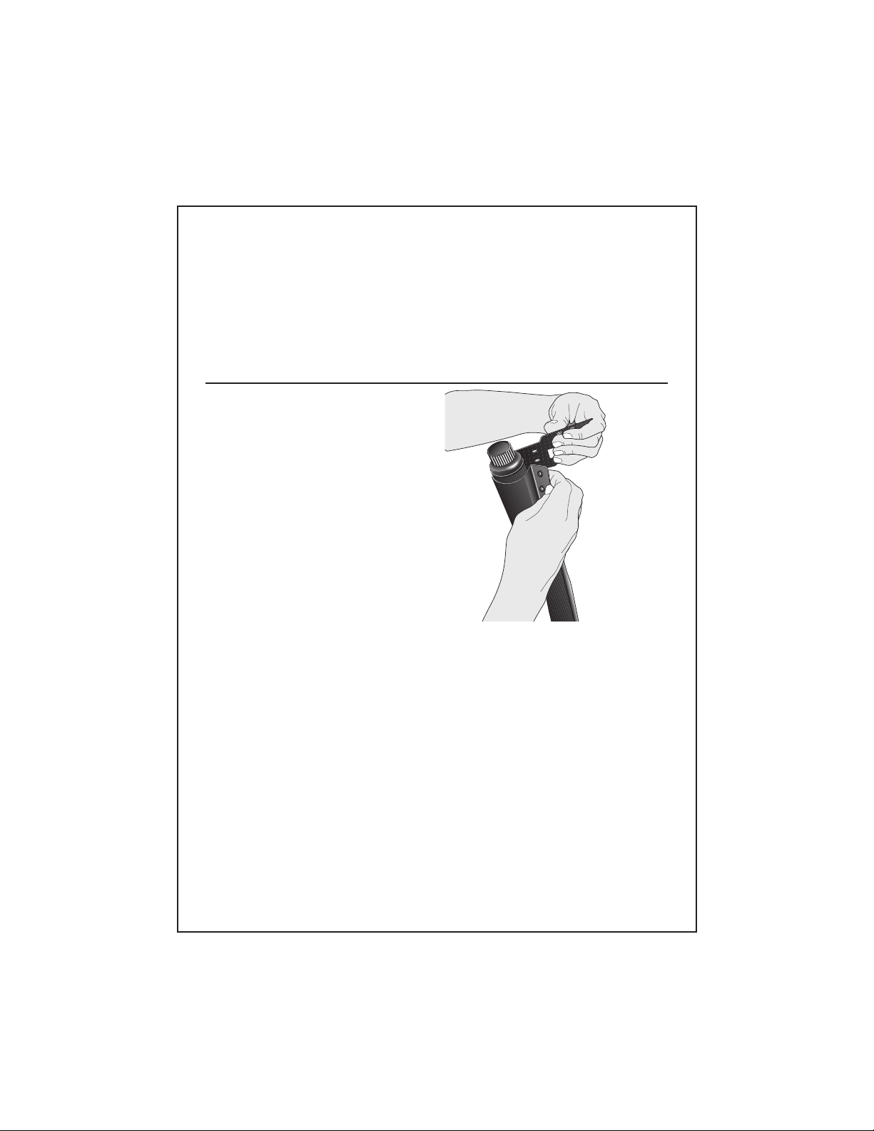
Diagram 6
904 Assembly Procedures
To install the 904 electronic console, take the following steps:
1. Remove the handrail clamp from its box. Take the long and
short screws out of the handrail clamp using your fingers or
a Phillips head screwdriver. Set the screws aside.
2. Position the handrail clamp over the right handrail’s
micro-adjustment knob as shown in Diagram 6. Place
a hand on either side of the handrail clamp to gently
pull it apart so that you can slide it onto the handrail’s
foam grip and into position (about 8 inches above the
base of the foam grip).
Important: Do not mount the clamp on the painted surface
of the handrails.
page 9
Page 10
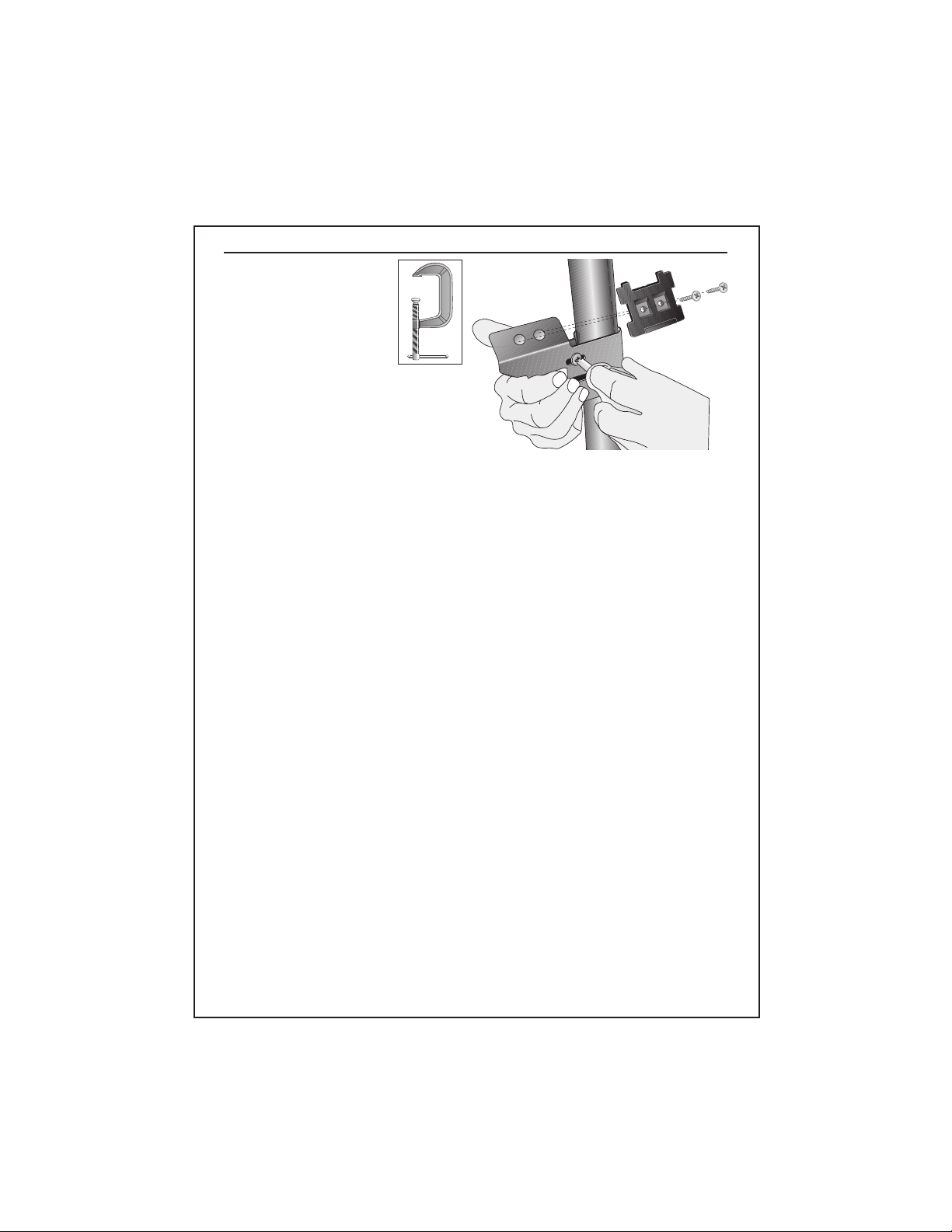
Diagram 7
C clamp
3. Insert the long screws through the mounting holes on
the clamp. See Diagram 7. You may need to squeeze
the ends of the clamp together to install the screws.
Tighten the screws using a Phillips head screwdriver
until the clamp remains securely in place. A gap
should remain between the opposite sides of the
clamp. See Diagram 7.
Note: If you have difficulty holding the clamp together, you
may want to use a C clamp (see insert on Diagram 7) to
help compress the clamp ends while you tighten the
screws.
4. Unlock and remove the mounting bracket from the
back of the electronic console. (Unlock the mounting
bracket by pushing it down toward the base of the
console.) Refer to Diagram 2 on page 6.
page 10
5. Position the mounting bracket onto the handrail clamp so
that the smooth side of the plate is facing you. Refer to
Diagram 7. Secure the mounting bracket by inserting the
two short screws. Tighten the screws into the recessed
holes on the mounting plate using the Phillips head
screwdriver. Do not over tighten the screws because too
much pressure may crack the plastic mounting plate.
6. Unwrap the reed switch wire. The reed switch wire has a
connector on one end and the oblong-shaped reed switch
on the opposite end. Refer to Diagram 5 on page 8.
Page 11

Diagram 8
7. Position the electronic console over the handrail
clamp and plug the connector into the receptacle. See
Diagram 8. Do not force the connection. The connector is designed to engage in one direction only. A tab
on the connector and a slot on the receptacle help you
determine the proper alignment.
8. Slide the electronic console onto the mounting
bracket. It should “click” into place as you slide it
toward the rear of the treadmill.
9. Attach the C clips around the handrail as shown in
Diagram 5 on page 8. Position the slight protrusion on
the C clip around the reed switch wire and microadjustment knob cable. Squeeze the C clips together
to close them and secure the wires in place.
10. With the electronic console successfully assembled,
continue to
InstalIing the Mounting Pads.
page 11
Page 12

Diagram 9
Installing the Mounting Pads
Two adhesive-backed foam pads (one thick and one thin pad)
accompany your electronics option package. The thick pad is
used as a spacer and you place the reed switch on it. The thin
pad is positioned onto the flywheel and becomes the base for
the magnet.
CAUTION: Both pads require a 24-hour period to bond
properly to the equipment. Do not operate the treadmill
during this time.
Place mounting
pad here
page 12
To install the mounting pads to the flywheel and side rail on your
903 or 904 treadmill, take the following steps:
1. Locate the area on the side rail between the right roller
guard and the deck of the treadmill. See Diagram 9.
Note: Right and left are determined by standing behind the
rear roller and facing the handrail(s).
Page 13

Diagram 10
Thick mounting pad
2. Remove the paper backing from one side of the thick pad
and press the pad firmly in place between the roller guard
and the deck of the treadmill. See Diagram 10.
3. Make a
copy
of the template shown in Diagram A. See
Appendix A. Cut along the dotted lines. Carefully cut away
the shaft section and the magnet mounting pad island.
4. Lay the template against the right flywheel. Use a pencil to
mark the outline for the magnet mounting pad. Remove the
template.
page 13
Page 14

Diagram 11
5. Remove the paper backing from one side of the thin pad
and press the pad firmly in place onto the flywheel. See
Diagram 11.
6. To mount the magnet and reed switch continue with the
steps below,
Attaching the Magnet and Reed Switch.
Attaching the Magnet and Reed Switch
For the electronic console displays to operate properly, a magnet
and reed switch need to be precisely installed. The magnet is
mounted to the flywheel and the reed switch is placed on the
side rail. Mounting pads indicate where you need to mount the
hardware. Be sure to follow the previous instructions
the Mounting Pads
before attaching the magnet or reed switch.
Installing
page 14
To install the magnet and reed switch, take the following
steps:
CAUTION: To ensure the integrity of the reed switch,
lower the handrails before mounting the reed switch.
Allowing excess wire near the flywheel eliminates the
possibility that the reed switch will be pulled out of
position. If you are not sure how to lower the handrails,
refer to your Owner’s Manual.
Page 15

Diagram 12
1. Remove the paper from the adhesive strip on the
flywheel’s foam mounting pad.
2. Wipe the back of the magnet with a dry clean, soft cloth.
Position it over the foam mounting pad on the flywheel and
press it onto the adhesive strip. Check that it is securely
mounted. See Diagram 12.
3. Wipe the base of the reed switch (the “base” is the
side opposite the ++) with a clean cloth.
CAUTION: Check the alignment of the +’s on the reed
switch with the magnet before adhering the reed
switch onto the side rail mount. For the electronics to
operate properly, the magnet can only pass over one
of the +’s on the reed switch.
4. To check the alignment between the magnet and reed
switch, move the flywheel slightly so that you can
place the base of the reed switch onto the foam
mounting pad. You should be able to see and read the
positive (+) signs. Position the reed switch between
the roller guard and deck so that the magnet passes
over one of the “+” markings on the reed switch.
Important: If the magnet passes over both “++” on the
reed switch, a false count or an erractic display can appear
on the electric console.
page 15
Page 16

Diagram 13
5. Remove the paper to expose the adhesive strip that is on
the foam mounting pad. Press the reed switch onto the
pad. Be sure that the reed switch is positioned so that the
wires are easily routed up the handrail. See Diagram 13.
6. Rotate the flywheel by hand to make sure that the magnet
and reed switch are secure and are not rubbing on each
other or on the treadmill. Check that the reed switch wire is
clear of the flywheel. If the magnet and flywheel are not
correctly aligned you may get incorrect readings on the
display. Reposition the magnet and reed switch if
necessary.
7. Secure the handrails into an upright position.
page 16
8. Check the wires to be sure no excessive amount of
wire hangs down where it could cause entrapment or
injury to someone. Realign the wire and move the C
clips along the handrail if necessary.
9. DO NOT OPERATE the treadmill for a 24-hour period.
The adhesive on the mounting pads requires this
amount of time to bond properly.
Page 17

Diagram 14
Using the Electronic Console
The electronic console provides multiple features and an easyto-read LCD display that lets you review your progress as
you work out. The three buttons on the console let you
control what information you want to display.
The features, TIME, SPEED, DISTance, and CALORies,
appear sequentially while in SCAN mode or you can
“select” and display one particular feature. See Diagram 14
below. To use and enjoy the electronic console to the fullest
extent, please take time to review the following information.
R
USA
Electronic Console Buttons
SELECT— turns the console ON. The electronic console
automatically starts up in SCAN mode which sequentially
displays each feature (TIME, SPEED, DISTance, and
CALORies) as you work out. While in the SCAN mode, the
feature’s icon appears and blinks on the display. Applying
constant pressure to the SELECT button causes the display to
SCAN faster.
page 17
Page 18

To hold on one particular feature, press the SELECT button
while the feature (such as TIME) is being displayed. The icon
stops blinking. To return to SCAN mode, press the SELECT
button one more time.
The electronic console automatically shuts off when the
treadmill is not in use after approximately 4 minutes.
CLEAR— resets the displays back to zero. You can also
use the CLEAR button in conjunction with the SET button
to predetermine the time or distance of your workout. See
Setting the Timer or Setting the Distance.
SET— is used in conjunction with the SELECT and CLEAR
buttons to predetermine the time or distance of your
workout.
Electronic Console Displays
TIME—shows how long you
have been working out in
minutes and seconds. To set
the duration of your workout,
refer to
Setting the Timer
SPEED— displays your
current workout pace by
calculating and averaging
your approximate kilometers
per hour.
.
page 18
DISTANCE— continuously
counts the total number of
kilometers accumulated
during your workout. It can
record up to 99.5 kilometers
before starting over at zero.
Page 19

PULSE—shows your heart
rate if you have attached and
are using the ear clip. Refer to
Choosing a Target Heart
Rate
. You can also set an
alarm to indicate when you
reach your target heart rate.
CALORIES - shows the
estimated total number of
calories burned during your
workout.
Setting the Timer
The timer lets you set the duration of your workout. When
the selected amount of time is up, an alarm beeps for about
10 seconds. To set the timer, take the following steps:
1. When TIME is displayed, press the SELECT button.
The icon stops blinking and TIME continues to count
down.
2. Press the CLEAR button to reset the display to zero.
3. Press the SET button to choose the amount of time
you want to work out. The TIME display advances in
1 minute increments. You can select up to 99 minutes
before the display returns to zero.
4. Press the SELECT button to start the countdown.
page 19
Page 20

Diagram 15
page 20
Setting the DISTANCE
If you have a specific number of kilometers that you want
to travel during your workout, use this feature. An alarm
sounds when you reach the specified distance. To set the
distance, take the following steps:
1. When DISTANCE is displayed, press the SELECT
button. The icon stops blinking.
2. Press the CLEAR button to reset the display to zero.
3. Press the SET button to choose the distance that you
want to travel. You can set distance in 0.5 increments
and select up to 99.5 kilometers.
4. Press the SELECT button to start the countdown.
Choosing a Target Heart Rate
Studies show that to achieve the benefits of aerobic exercise, it
is necessary to work out hard enough to raise your heart rate to
a certain minimum level called the “training zone.” Your training
zone depends on your age and level of fitness.
HEART RATE TRAINING ZONE
190
185
190
180
170
160
150
140
130
YOUR HEART RATE
120
110
100
90
80
70
180
175
170
165
160
132
107
YOUR AGE
128
104
155
124
101
150
120
98
152
148
144
140
136
124
20
RECOMMENDED TRAINING ZONE
120
117
114
110
25 30 35 40 45 50 55 60 65 70 75
116
145
140
135
MAX.
HEART
RATE
112
108
80% OF
MAX.
94
HEART
RATE
91
88
65% OF
MAX.
HEART
RATE
Page 21

Diagram 16
Diagram 15 shows your recommended heart rate training
zone which is calculated using your age and your maximum attainable heart rate. The chart is based on a resting
heart rate of about 72 for males and 80 for females. The
optimum training zone is between 65% and 80% of your
maximum heart rate. For efficient aerobic exercise and to
obtain significant cardiovascular benefits, work hard
enough to keep your heart rate in this zone. You will obtain
the greatest fat-burning benefits when you exercise within
the optimum training zone for at least 20 minutes, three or
four times a week.
Keep in mind that this zone is an approximation, to be used
as a guideline—individual heart rates vary according to
several physiological factors. To determine your training
zone, find your age on the diagram, and then find the line
where they intersect. For example, if you are 35 years old,
your training zone is between 110 and 148 beats per
minute. Remember this zone and set your target heart rate
to the lower number of the zone. Watch the display as you
work out and keep your heart rate within this zone.
To choose a target heart rate and set the alarm, take the
following steps:
1. Plug the pulse detector into the electronic console and
attach the ear clip to your ear lobe. Attach the collar
clip to your workout clothing near your neck. See
Diagram 16.
page 21
Page 22

Note: The located in the upper left corner of the
display begins to blink once a heart rate is detected.
2. When the (PULSE) icon is displayed, press the
SELECT button. The icon stops blinking.
3. Press the CLEAR button (“OFF” appears on the display).
4. Press the SET button (“50” appears on the display).
Continue to press the SET button (number increments in
units of 5) until you reach your target heart rate. Your
target heart rate should be the lowest number shown in the
Heart Rate Training Zone. Refer to Diagram 15.
5. To enter the number, press SELECT. An alarm rings every
5 seconds until you reach your target heart rate. If you
drop below your target heart rate, the alarm begins again.
Important: The alarm stops anytime it cannot detect a
heart beat. This can ocur if you remove the ear clip or the
ear clip becomes dislodged. Occasionally, due to
medication, caffiene, or physiology of the heart (such as
an irregular heart beat) the pulse detector cannot correctly
detect a heart beat. Verify the accuracy of the heart rate
reading by taking your pulse one or twice during your
workout.
6. The electronic console retains your target heart rate in
memory (even when the electronic console turns OFF)
until you erase (CLEAR) it. To erase the target heart rate
zone and turn OFF the alarm, press the SELECT button
until the stops blinking. Press the CLEAR button and
press SELECT again.
page 22
Resetting Your Workout Statistics
You can clear the displays and reset your workout statistics to
zero by pressing all three buttons (SELECT, CLEAR, and SET)
at the same time. All the features on the display appear and
then TIME displays and the count up continues.
Page 23

Maintaining the Electronic Console
Use a damp, clean cloth after every workout to wipe off any
perspiration that might have fallen on the electronic console.
Periodically, clean the electronic console using a cloth
dampened with a mild dishwashing detergent solution. Rinse the
solution off with a clean, damp cloth. Thoroughly dry the
electronic console before using it.
CAUTION: Do not immerse the electronic console in liquid.
Replacing the Batteries
Your electronic console comes equipped with fresh batteries
already installed. Over time the batteries can wear out and will
need to be replaced. Signs that the batteries are low include:
• fading LCD display
• erratic display function
• failure to turn ON when the SELECT button is pressed
• no display when the running belt is moving
To replace the two (A-76 type) batteries, take the following
steps:
1. Carefully remove the electronic console from the
handrail’s mounting bracket by sliding it forward.
page 23
Page 24

Diagram 17
Diagram 18
2. Disconnect the reed switch wire by gently pulling the
connector out of the receptacle. See Diagram 17.
page 24
3. Remove the back of the electronic console by
unscrewing the four Phillips head screws. See
Diagram 18. Set the screws aside.
4. Use your finger to pull up on the battery holder and
slide the battery out. You may want to use your
screwdriver to help push the old battery out of its
holder. Discard the batteries.
Page 25

Diagram 19
+
5. Reinsert two fresh batteries. Remove the existing
batteries from the unit and reinsert two fresh (A-76
type) alkaline batteries. The positive (+) side should be
facing you. See Diagram 19.
Note: All the LCD segments momentarily appear when
the fresh batteries are installed.
6. Replace the back of the electronic console by inserting
the four Phillips head screws back into place. Tighten
the screws using the Phillips head screwdriver.
7. Reconnect the reed switch wire into the console. For
the 903 treadmill, be sure to route the wire through
the hole on the handrail clamp before reconnecting the
wire.
8. Slide the console back onto the mounting bracket.
9. Reset the display by pressing all three buttons (SELECT,
CLEAR, and SET) at the same time.
10 . Press the SELECT button if you wish to turn the electronic
console ON.
page 25
Page 26

Appendix A
Put magnet
mounting pad here
Shaft
cut-away
page 26
Make a copy of this template or trace the pattern onto a different sheet of paper before cutting along the dotted lines.
Page 27

R
USA
Precor Incorporated
P.O. Box 3004
Bothell, WA USA 98041-3004
Precor is a registered trademark of Precor Incorporated.
© 1996 Precor Incorporated.
P/N 36834-102
Web version 9/98
Specifications subject to change without notice.
1-800-4-PRECOR
NOTICE:
Precor is widely recognized for its innovative, award winning designs of exercise equipment. Precor
aggressively seeks U.S. and foreign patents for both the mechanical construction and the visual aspects
of its product design. Any party contemplating the use of Precor's product designs is hereby forewarned
that Precor considers the unauthorized appropriation of its proprietary rights to be a very serious matter.
Precor will vigorously pursue all unauthorized appropriation of its proprietary rights.
page 27
 Loading...