

Page 1

Light Commercial EFX® Owner’s Manual
COMMERCIAL PRODUCTS DIVISION
Page 2

COMMERCIAL PRODUCTS DIVISION
IMPORTANT SAFETY INSTRUCTIONS
When using the EFX®, basic precautions should always be followed, including the following:
• To ensure your safety and to protect the unit, read all the instructions
before assembling and using the self-powered EFX®534.
• To ensure the proper use and safety of the EFX, make sure that all users
read this manual. Please make this manual a part of your staff’s training
program. Remind the users that before beginning any fitness program,
he or she should obtain a complete physical examination from his or her
physician.
Il est conseillé de subir un examen médical complet avant d’entre-prendre
tout programme d’exercise. Si vous avez des étourdissements ou des
faiblesses, arrêtez les exercices immédiatement.
DANGER —
WARNING —
• Do not allow children or those unfamiliar with its operation on or near
the EFX. Do not leave children unsupervised around the EFX.
• Never leave the EFX unattended with the optional battery recharger
plugged in. Unplug the unit from the outlet when it is not in use, before
cleaning it, and before putting on or taking off parts.
• Assemble and operate the EFX on a solid level surface. Locate the EFX
a few feet from walls or furniture. Check the unit before each use and
verify that all fasteners are secure. Maintain the EFX in good working condition. (See the
• Use the EFX only for its intended use as described in this manual. Do
not use accessory attachments that are not recommended by the manufacturer—such attachments might cause injuries.
• Use care when getting on or off the EFX. Use the stationary handrail
whenever possible. Keep your body and head facing forward. Never
attempt to turn around on the EFX.
• Wear proper exercise clothing and shoes during a workout—no loose
clothing. Tie long hair back.
To reduce the risk of electrical shock, always unplug the
optional battery recharger from its power source before cleaning or performing any maintenance tasks.
To reduce the risk of burns, fire, electric shock, or injury to
persons, take the following precautions:
Maintenance
section).
• Do not rock the unit. Do not stand on the display console or casing.
• Never drop or insert any object into any opening. Keep towels and
hands away from moving parts.
IMPORTANT SAFETY INSTRUCTIONS
page 2
• If you purchased the optional POLAR® chest strap, review the guidelines found in the
supplied with that option.
• Do not overexert yourself or work to exhaustion. If you feel any pain or
abnormal symptoms, stop your workout immediately and consult your
physician.
• Keep all electrical components away from liquids to prevent shock. Do not
set anything on the casing, handrails, or display console. Place liquids
only in the appropriate receptacles.
Precor Heart Rate Option Owner’s Manual
that is
Page 3
COMMERCIAL PRODUCTS DIVISION
IMPORTANT SAFETY INSTRUCTIONS
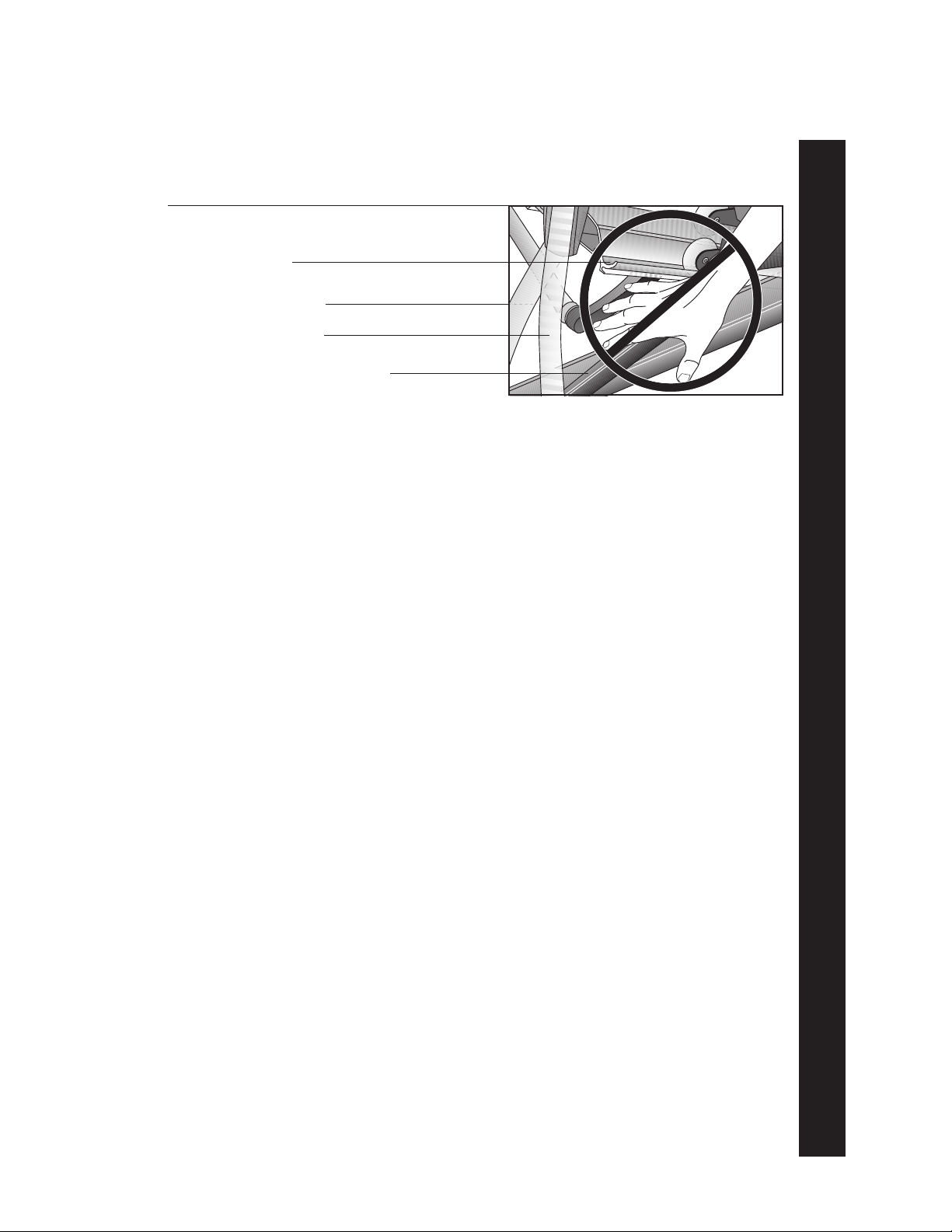
Diagram 1
Avoid injury from the roller
arm mechanism.
Ramp
Front cover
Handlebar
Lower pivot roller arm
(handlebar linkage)
• Never place your hand(s) or feet in the path of the roller arm because
injury may occur to you or damage may occur to the equipment. Refer
to Diagram 1.
• Never operate the unit if it is damaged, if it is not working properly, if it
has been dropped, or dropped in water. Return the unit to a service
center for examination and repair.
• Keep the optional battery recharger cord away from heated surfaces.
• Do not operate where aerosol (spray) products are being used or where
oxygen is being administered.
• Do not use outdoors.
• Do not attempt to service the EFX yourself other than the assembly and
maintenance instructions found in this manual. Refer to
Obtaining Service
.
HAZARDOUS MATERIALS AND PROPER DISPOSAL
The EFX534 has an internal battery which must be removed before the EFX is
scrapped. The battery contains materials which are considered hazardous to the
environment. Proper disposal of the battery is required by federal law.
To remove the battery from the EFX, take the following steps:
CAUTION: Unplug the battery recharger and disconnect it from
its receptacle at the rear of the EFX.
Tools required: Phillips head screwdriver and hex wrench set.
1. Remove both the right and left rear covers from the EFX.
2. Remove the top rear cover.
3. Unplug the black and red battery wires from the circuit board.
4. Separate the circuit board from the battery by removing four screws.
5. The battery is held in place with a metal bracket. Lift the battery away from
the bracket.
6. Dispose of the battery according to the federal Hazardous Waste Regulations.
SAFETY APPROVAL
When identified with the ETL-c logo, the EFX has been tested and conforms to
the requirements of CAN/CSA-E-335-1/3-94, Safety of Household and Similar
Electrical Appliances.
IMPORTANT SAFETY INSTRUCTIONS
SAVE THESE INSTRUCTIONS
page 3
Page 4

COMMERCIAL PRODUCTS DIVISION
Table of Contents
Important Safety Information ...........................................2
Hazardous Materials and Proper Disposal .............................. 3
Safety Approval ..................................................................... 3
RFI — Radio Frequency Interference ..................................... 6
European Applications ........................................................... 6
EFX® Self-powered Features .................................................. 7
Obtaining Service ................................................................... 7
About this Manual .................................................................. 8
Unpacking the EFX
Standard Equipment ............................................................... 9
Other Equipment .................................................................... 9
Acquiring the Appropriate Tools .............................................. 9
Hardware Kit .......................................................................... 10
®
..................................................................................................
Setting Up the EFX .........................................................11
Installation Requirements ....................................................... 11
Assembly Instructions ........................................................... 11
Removing the Locking Pin...................................................... 21
Supplying Power To the EFX534 ............................................. 22
Testing the Heart Rate Display ............................................... 22
Custom Setting Mode ....................................................23
Changing the Custom Settings ............................................... 23
Determining the Units of Measure .......................................... 24
Setting a Workout Time Limit.................................................. 25
Setting a Pause Time Limit .................................................... 25
Viewing the Odometer, Hours of Use,
Software Version, and Error Log ............................................. 25
Using CSAFE Standard Equipment ........................................ 26
9
page 4
The EFX®534 Display .....................................................27
Features on the Display Console ............................................ 27
User Setup Prompts ............................................................... 28
Using QuickStart During the Setup Prompts .......................... 29
Center Display........................................................................ 30
SmartRate® Display ............................................................... 31
Informational Displays Prior to Shutdown ............................... 31
Keys on the Display Console.................................................. 32
Page 5

COMMERCIAL PRODUCTS DIVISION
Table of Contents
®
Exercising on the EFX
The Heart Rate Feature .......................................................... 34
Utilizing the SmartRate® Feature............................................ 34
Removing the Locking Pin...................................................... 35
Workout Tips .......................................................................... 35
Using the Handlebars ............................................................. 36
Using the Stationary Handrail ................................................. 36
Changing the Display Features using the Select Key ............. 36
Quick Steps to Working Out ................................................... 37
Cooling Down After a Workout ................................................ 38
Pause, Cool Down and Exit Features ..................................... 38
Inserting the Locking Pin ....................................................... 39
Courses........................................................................... 40
.....................................................................................
34
Manual Mode and the QuickStart Key .................................... 40
Hill Climb Course ................................................................... 40
Interval Course ....................................................................... 40
Cross Training Course............................................................. 41
Weight Loss Course ............................................................... 42
Maintenance ...................................................................43
Inspection .............................................................................. 43
Cleaning the Equipment ......................................................... 43
Storing the POLAR® Chest Strap ........................................... 44
Servicing the EFX and Long Term Storage ............................. 44
Symptoms of a Low Battery ................................................... 44
Using the Battery Recharger and Its Power Cord .................... 44
Replacing the Battery ............................................................. 45
Battery Recharger Power Cord ............................................... 45
Exploded Views ...................................................................... 46
Warranty Registration Card ..................................................... 53
Warranty................................................................................. 55
Specifications ............................................................ back cover
page 5
Page 6

COMMERCIAL PRODUCTS DIVISION
RFI — RADIO FREQUENCY INTERFERENCE
Federal Communications Commission Part 15
The EFX has been tested and found to comply with,
• the IEC EMC Directive (international electromagnetic compatibility certification)
• the limits for a Class A digital device, pursuant to Part 15 of the FCC Rules.
These limits are designed to provide reasonable protection against harmful
interference in a commercial installation. The EFX generates, uses, and can
radiate radio frequency energy and, if not installed and used in accordance
with the owner’s manual instructions, may cause harmful interference to radio
communications. Operation of the EFX in a residential area is likely to cause
harmful interference. If this occurs, the user will be required to correct the
interference at his or her own expense.
CAUTION —
Per FCC rules, changes or modifications to the EFX
not expressly approved by Precor, could void the
user’s authority to operate the equipment.
Canadian Department of Communications
This digital apparatus does not exceed the Class A limits for radio noise emissions
from digital apparatus set out in the Radio Interference Regulations of the Canadian
Department of Communications.
Le présent appareil numérique n’émet pas de bruits radioéélectriques dépassant les
limites applicables aux appareils numériques de la Class A prescrites dans le
Règlement sur le brouillage radioélectrique édicté par le ministére des Communications du Canada.
EUROPEAN APPLICATIONS
This product conforms to the requirements of the European Council Directive 89/336/
EEC, Electromagnetic Compatibility and has been tested to the following standards:
EN55022, Limits & Methods of Measurement of Radio Interference, Information
Technology Equipment (Class A).
EN50082-1, Generic Immunity Standard for Residential, Commercial and Light
Industrial Products (Class A).
This product additionally conforms to the requirements of the European Council Directive
73/23/EEC, Low Voltage Directive and has been tested to the following standard:
IEC 335-1, Safety of Household and similar Electrical Appliances.
page 6
European Applications
This product has been tested to the requirements of EN55022, “Limits & Methods of
Measurement of Radio Interference, Information Technology Equipment.” Per that
standard, the EFX534 is a Class A product. In a domestic environment, this product
may cause radio interference, in which case the user is responsible to take adequate
measures to alleviate the interference.
Page 7
COMMERCIAL PRODUCTS DIVISION
EFX® SELF-POWERED FEATURES
The power source for the EFX is the user. When a person works out on the EFX and
moves the foot pedals at a stride rate above 40 strides per minute, the power that
is generated allows the EFX to function properly.
Informational displays appear when the battery is low or when the user has stopped
pedaling during a workout. The display provides minimal instructions to let you
know what to do to retain power. If the messages are ignored, the EFX will begin
shutdown procedures to maintain the charge of the battery. Refer to page 31,
Informational Displays Prior to Shutdown
.
An optional battery recharger can be purchased and provides sustained power to
the EFX. If you plan to customize your unit, the optional battery recharger is highly
recommended. To purchase the optional battery recharger, check with your dealer.
OBTAINING SERVICE
Do not attempt to service the self-powered EFX® yourself except for the maintenance tasks described in this manual. The EFX does not contain any user-serviceable parts. For information about product operation or service, contact an authorized
Precor Commercial Products Customer Support Representative at 1-888-665-4404.
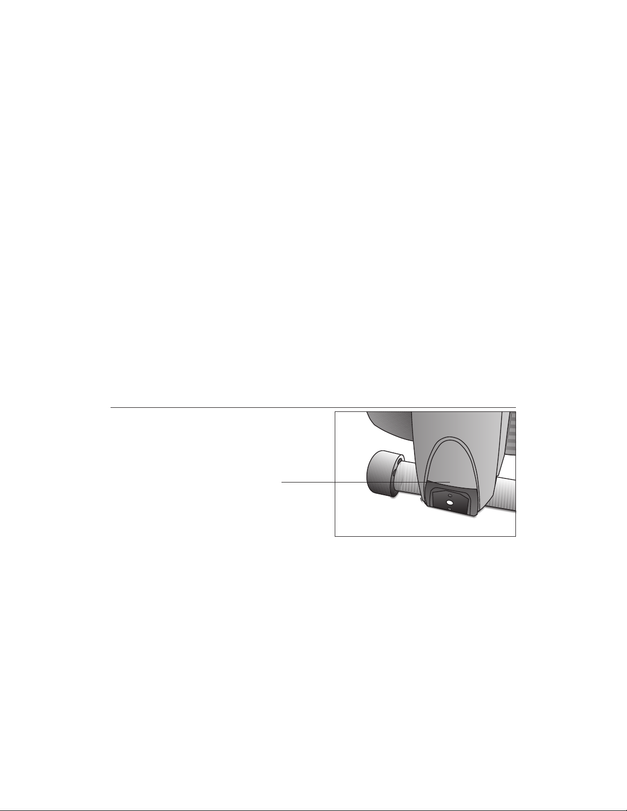
Diagram 2
EFX serial number location.
Serial number label location
To help Customer Support personnel expedite your call, have your serial number
available. The serial number can be found on a label near the power receptacle on
the rear cover. Refer to Diagram 2. If you have any questions regarding the EFX,
use the model and serial numbers whenever you call your Precor dealer or servicer.
Model number: EFX®534
Unit number: _____ Serial number: _____________________________
Unit number: _____ Serial number: _____________________________
Unit number: _____ Serial number: _____________________________
page 7
Page 8

COMMERCIAL PRODUCTS DIVISION
ABOUT THIS MANUAL
Inside this manual, you will find instructions for installing and using the self-powered
EFX. To maximize the use of the EFX, please study this manual thoroughly. The
manual uses the following conventions for identifying special information:
Note: Contains additional information.
Important: Indicates information to which you should pay special attention.
CAUTION: Indicates steps or information necessary to prevent harm to your-
self or damage to the equipment.
WARNING — Provides instructions to prevent electrical damage to
the equipment and prevent injuries to yourself.
DANGER — Indicates steps you must take to prevent electrical shock.
page 8
Page 9

COMMERCIAL PRODUCTS DIVISION
Unpacking the EFX
Thank you for purchasing the self-powered Precor EFX®534.
Important: Before using the EFX, we urge you to familiarize yourself and your
staff with the entire Owner’s Manual. Understanding this manual will help you and
your customers use the EFX safely and successfully.
Your EFX is carefully inspected before shipment so it should arrive in good operating
condition. Precor ships the unit in the following pieces:
❑ Base frame assembly ❑ Base frame stabilizers (left and right)
❑ Upright support ❑ Display console
❑ Handlebars (left and right) ❑ Bracket cover
❑ Hardware kit and owner’s manual
CAUTION: This unit weighs over 230 pounds (105 kilograms). To prevent
injury to yourself or damage to the equipment, obtain appropriate assistance
before removing the unit from the pallet.
If any items are missing, contact your Precor Commercial Products Service Representative at 1-888-665-4404.
®
STANDARD EQUIPMENT
The EFX®534 incorporates the Precor SmartRate® and Heart Rate features into its
display console. Devices, such as FitLinxx®, that are CSAFE compatible, can also
be attached.
Note: An optional POLAR® chest strap can be purchased and worn during a workout.
The chest strap transmits the user’s heart rate to the display console’s receiver.
OTHER EQUIPMENT
Optional equipment available through your dealer includes:
• Battery recharger
• POLAR® chest strap.
If you are interested in obtaining Precor option kits for your unit, check with your
dealer. For Customer Support, see
Obtaining Service
ACQUIRING THE APPROPRIATE TOOLS
Obtain the following tools
❑ Wire cutter ❑ Phillips head screwdriver
❑ Rubber mallet ❑ Hex torque wrench
before
assembling the EFX.
on page 7.
❑ Two 9/16" combination wrenches (open-end and box)
❑ SAE Standard socket set with socket extension for 1/2” and 9/16" bolts
page 9
Page 10
COMMERCIAL PRODUCTS DIVISION
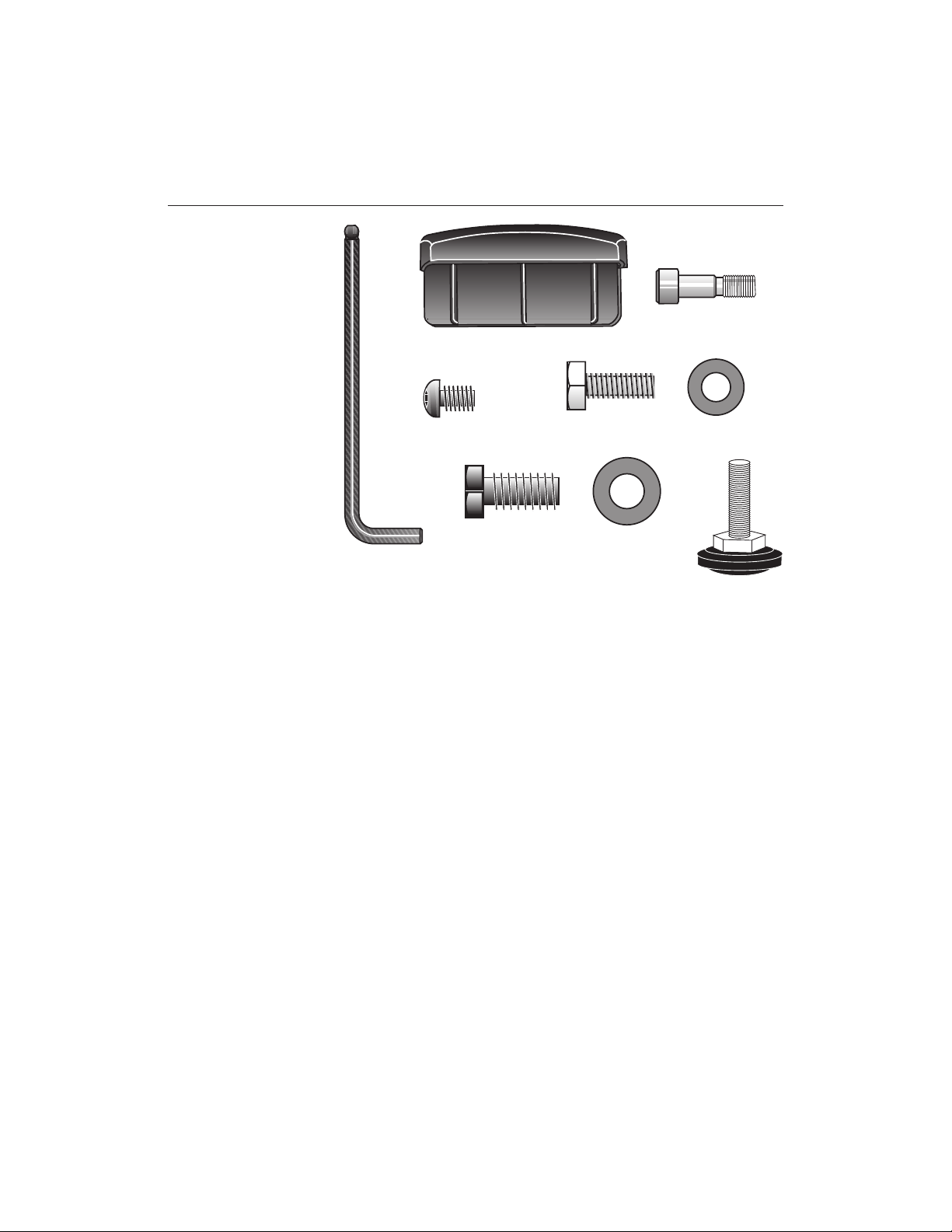
Diagram 3
EFX534
Hardware kit
HARDWARE KIT
Carefully unpack the parts from the shipping container. Open the Hardware Kit
and make sure that you have the following items as shown in Diagram 3:
C
B
F
D
G
A
E
H
J
❑ (A) 5/16-inch hex key — secures handlebars
❑ (B) End cap
❑ (C) Two shoulder bolts — install handlebars to lower pivot arms
❑ (D) Four Phillips-head screws — attach display console
❑ (E) Six 1-inch long x 5/16-inch diameter bolts — attach handlebars
❑ (F) Six small diameter washers — use with 5/16-inch bolts (E)
❑ (G) Eighteen 1-inch long x 3/8-inch bolts — attach upright and stabilizers to base
❑ (H) Eighteen large diameter washers — use with 3/8-inch bolts (G)
❑ (J) Height adjustor
If any items are missing, contact your dealer. If you need Customer Support,
refer to
Obtaining Service
on page 7.
Note: After assembling the EFX, be sure to store the hex key in a secure place.
The tool is used for maintenance procedures that are described in this manual.
page 10
Page 11

COMMERCIAL PRODUCTS DIVISION
Setting Up the EFX
You do not need any special knowledge or experience to set up the EFX. However,
because of the size and weight of the EFX, you will need to obtain appropriate
assistance during assembly.
®
INSTALLATION REQUIREMENTS
Follow these installation requirements when installing the EFX.
install the EFX according to the following guidelines, you could void the Precor
Limited Warranty.
• Set up the EFX on a solid, flat surface. Unpack and assemble the EFX close to
where you’ll use it. Make sure that the flat surface under the unit is smooth and
level. A level unit is required for the user’s safety and for proper operation.
• Provide ample space around the unit. Open space around the unit makes
for a safer mount and dismount.
• Fill out and mail the limited warranty card. The serial number is located on
a label at the rear of the unit near the optional battery recharger receptacle.
Write the serial number onto the Precor Limited Warranty card found on the
back cover of this manual. Refer to
number there as well.
Obtaining Service
If you do not
on page 7 and write the
ASSEMBLY INSTRUCTIONS
To assist you in the assembly, the items in the Hardware kit, shown in Diagram 3,
correspond to a particular letter in the alphabet. These letters appear throughout the
assembly instructions. Refer to Diagram 3 on page 10.
1. Obtain assistance. Place the shipping carton close to the location where
you plan to use the unit. Break down the side walls so that they lie flat. You
may need to cut the tie wraps that hold the base frame and roller arms to the
pallet.
2. Unpack the EFX534. Remove the packing materials and loose contents. Refer
to the list on page 9.
3. Move the unit to the location where you plan to use it. Once you attach
the handrails and base stabilizers, the EFX is difficult to move through a
standard door frame. Make sure to assemble the unit where it will not have to
be moved through any doorways.
CAUTION: Do not assemble the EFX if it is connected to the optional
battery recharger. Remove the battery recharger from the EFX prior to
assembly.
page 11
Page 12
COMMERCIAL PRODUCTS DIVISION
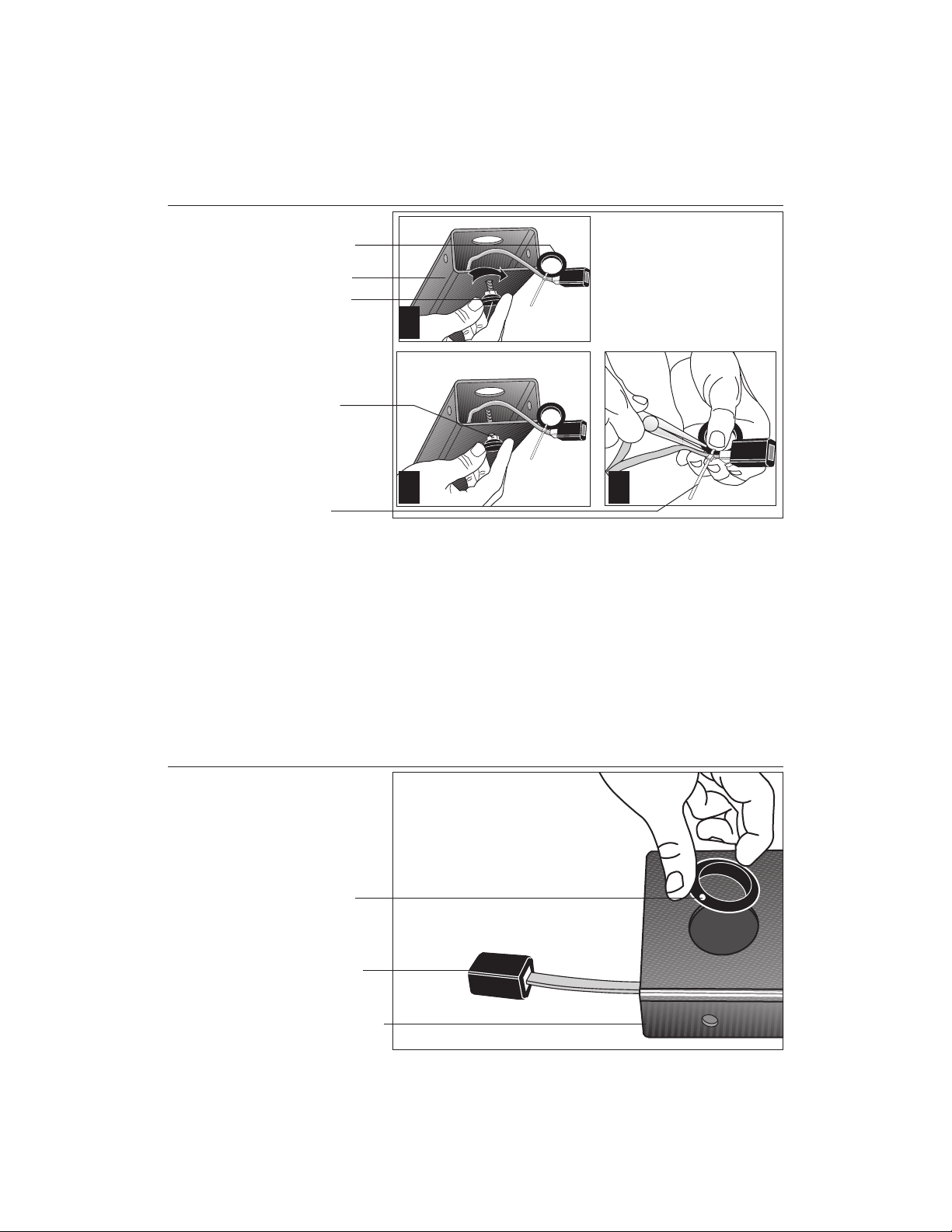
Diagram 4
Front base assembly.
Plastic grommet
Front base tube
Height adjustor
1
Tighten the height
adjustor so that the
nut is secure against
the front tube.
Cut the tie wrap that
secures the grommet
to the cable.
4. Cut the tie wrap securing the front base tube to the pallet. Discard the tie
wrap.
5. Thread the height adjustor to its lowest position. Diagram 4, #1 and #2.
Remove the height adjustor from the Hardware kit. Ask an assistant to lift the
front base tube while you insert the height adjustor. Turn the height adjustor so
that the threads appear inside the base tube. Tighten the nut (with a crescent
wrench) when the height adjustor is fully threaded into the front base tube.
2
3
Diagram 5
6. Cut the tie wrap holding the plastic grommet. Diagram 4, #3. Use a wire
cutter (or scissors) to remove the plastic grommet from the cable.
Front base assembly.
Plastic grommet
Cable receptacle
Front base assembly
7. Insert the plastic grommet. Diagram 5. Place the grommet into the hole on
the front base assembly. Press down so that it snaps into place.
page 12
Page 13
COMMERCIAL PRODUCTS DIVISION
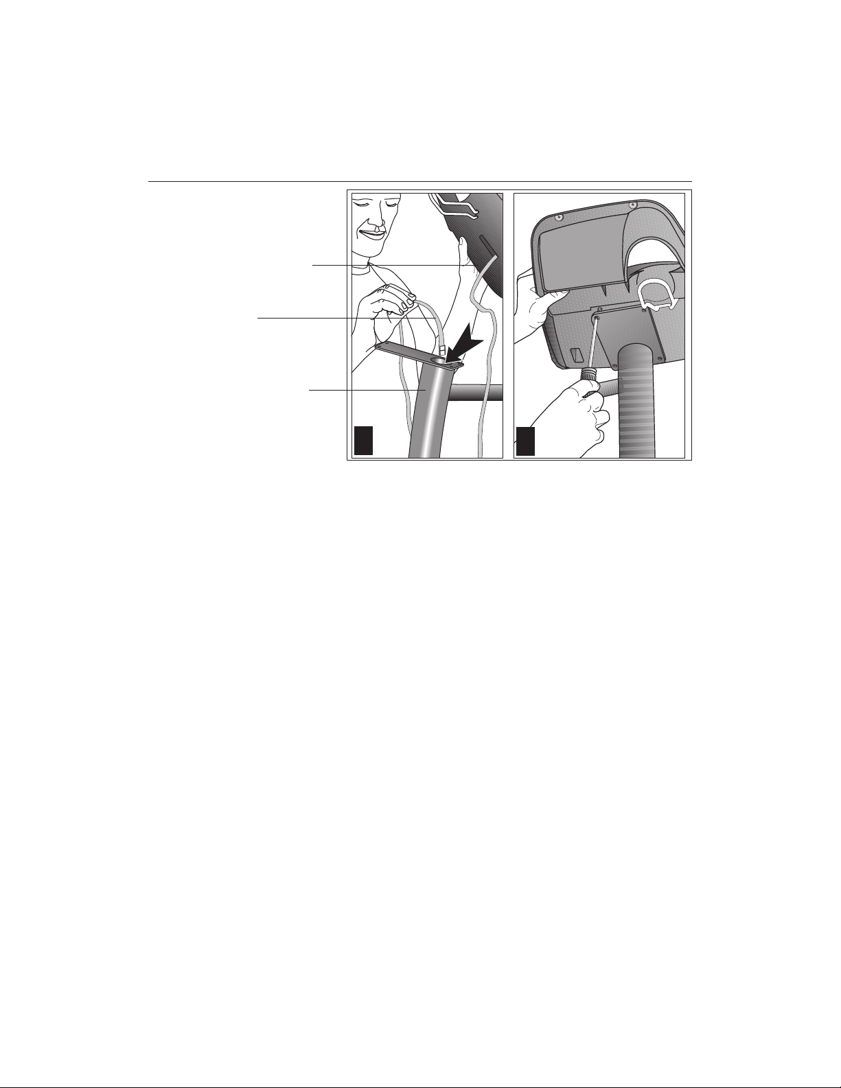
Diagram 6
Route the cable and
attach the display
console to the
upright support.
Display console
Cable
Upright support
1
2
8. Prepare for the attachment of the upright support to the base assembly.
Diagrams 6 and 7. Remove the four phillips-head screws (D), two bolts (G),
and two washers (H) from the Hardware kit. Place one washer (H) on each of
the two bolts (G). Keep the fasteners together.
CAUTION: Do not stretch, crimp, or damage the cable. Excess cable may
be gently pushed into the base assembly. Cables damaged by improper
installation will not be covered by the Precor limited warranty.
9. Route the display console cable through the upright support. Diagram 6, #1
Remove any tape or wire ties on the cable. Have an assistant hold the upright
support securely while you grasp the display console in one hand and route the
cable through the upright support with the other.
10. Attach the display console. Diagram 6, #2. Use the four phillips-head
screws (D) to attach the display console to the upright support. Have your
assistant hold the upright support securely while you align the mounting holes
and tighten the screws.
page 13
Page 14
COMMERCIAL PRODUCTS DIVISION
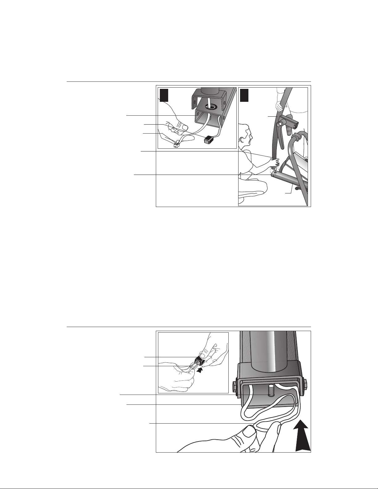
Diagram 7
Route the cable
through the grommet
and attach the upright
support.
Base tube
Cable receptacle
Cable connector
Have your assistant
hold the upright
support while you
secure it to the base.
Two bolts (G)
with washers (H)
1
2
Upright
support
Base
assembly
11. Position the upright support over the base. Diagram 7. Have your assistant
move the upright support close to the front of the base assembly while you
thread the cable through the grommet hole and out the front of the base tube
(see inset #1). Make sure that the display console (on the upright support)
faces the rear of the unit (see inset #2).
CAUTION: As you assemble the unit, do not fully tighten the fasteners until
instructed to do so. Finger tighten the fasteners or use the hex key so that
the unit is stable, but the fasteners still allow room for adjustments.
Diagram 8
12. Secure the upright support to the base assembly. Diagram 7. Align the
mounting holes and thread the two bolts (G) with washers (H) through opposite
sides of the upright support and into the base assembly. Finger tighten each
bolt. Do not fully tighten the fasteners until the entire unit has been assembled.
Connect the
cables.
Cable receptacle
Cable connector
Height adjustor
threads
Base tube
Place excess cable
into the base tube.
page 14
Page 15
COMMERCIAL PRODUCTS DIVISION
13. Connect the cable. Diagram 8, inset. Insert the cable into its receptacle.
Just like a telephone connection, a definite "click" is heard when a good
connection is made. If you do not hear a "click," try reinserting the cable
connection again.
14. Push excess cable inside base tube. Diagram 8. Carefully, push any excess
cable behind the height adjustor threads that protrude from inside the base tube.
Diagram 9
Place the base
on supportive
blocks.
Adjustable rear pad
Base assembly
Supportive
wedge
15. Rotate the rear pads. Diagram 9, inset. Ask your assistant to stabilize the
unit while you rotate the rear adjustable pad to the highest position. This
procedure lifts the base assembly off the floor which provides better access
to the fasteners.
16. Place the base assembly on the supportive wedge. Diagram 9. Have an
assistant grasp and lift the upright support so that you can slide a wedge
(packing material) under the front of the unit.
page 15
Page 16
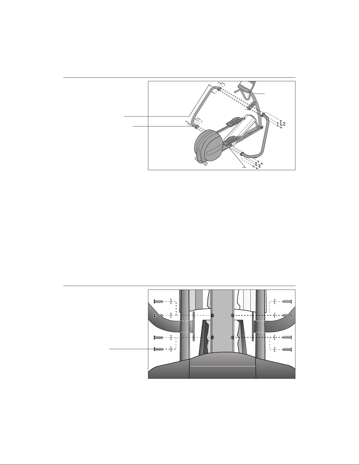
COMMERCIAL PRODUCTS DIVISION
Diagram 10
Attach the frame
stabilizers to the
upright support
brackets.
Bolts (G) and
washers (H)
Frame stabilizer
Upper section
Lower section
Upright
support
bracket
17. Attach the left and right frame stabilizers. Diagram 10. Proceed with one
side at a time. When you have installed the first stabilizer, perform the same
steps on the opposite stabilizer.
a. Remove four bolts (G) and four washers (H) from the Hardware kit. Place
a washer on each bolt and set the fasteners within easy reach of the unit.
b. Grasp one of the frame stabilizers and align it with the upright support bracket.
c. Insert the four bolts (G) with washers (H) through the frame stabilizer and
upright support bracket. See Diagram 10.
d. Thread all four bolts and washers until the frame stabilizer is secure. Do
not fully tighten the bolts until after the lower section is attached.
Diagram 11
page 16
e. Perform steps a through d on the opposite side.
Attach the lower
frame stabilizers
to the base
assembly.
Bolts
f. Carefully, align the mounting holes on the right and left frame stabilizer with
the base frame holes. Insert four bolts (G) and washers (H) on both sides.
Thread the bolts through the unit. See Diagram 11. You may need to adjust
and gently move the stabilizers up and down to get the mounting holes on
both sides of the base frame properly aligned.
g. Tighten the bolts so that the unit is stable, but leave room for final adjustments.
Do not securely tighten the bolts until the unit has been fully assembled.
Page 17
COMMERCIAL PRODUCTS DIVISION
Diagram 12
Tighten the
mounting bolts.
Upright support
bracket
Left frame stabilizer
Tighten the bolts
on the base
frame first.
Upright support
Base frame
1
2
3
18. Tighten all mounting screws using a 9/16" wrench. Diagram 12.
a. Ask for assistance to remove the supportive wedge from beneath the base
assembly and to turn the unit onto its side.
b. With the unit on its side, start at the base with the eight bolts that attach the
frame stabilizers to the base frame. Tightening these bolts first helps pull
the rest of the parts into alignment. Proceed with securely tightening the
bolts attached to the upright support bracket and the bolts that secure the
upright support to the base frame.
page 17
Page 18

COMMERCIAL PRODUCTS DIVISION
Diagram 13
Secure the
handlebars.
Protrusions
Handlebar
bracket
Tighten bolts securely.
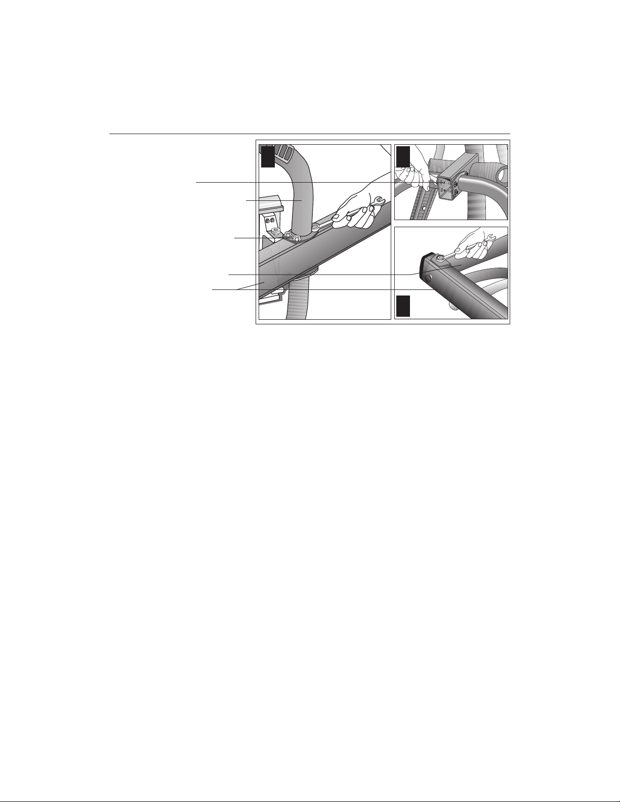
19. Attach the left and right handlebars. Diagram 13. Perform the following
steps on one side of the unit and then, repeat the steps on the opposite side.
a. Remove the three bolts (E) and washers (F) from the Hardware kit. Place
the washers on the bolts.
b. Attach one handlebar at a time. Note that the handlebars’ mounting holes
are smooth on one side and slightly protrude on the other side. Place the
protrusions against the handlebar brackets.
Diagram 14
c. Align the holes and insert the three bolts (E) and washers (F). Thread the
bolts (E) into the holes using your fingers.
d. Tighten the bolts securely using a 1/2-inch socket wrench.
e. Repeat steps a. through d. to secure the opposite handlebar.
Secure the
handlebars to the
pivot arm.
Shoulder bolt (C)
Handlebar
5/16-inch hex key
Pivot arm
page 18
Page 19

COMMERCIAL PRODUCTS DIVISION
20. Attach the handlebars to the pivot arm. Diagram 14. Proceed with one
handlebar at a time. When you have completed the installation steps for one,
perform the same steps for the opposite handlebar.
a. Remove the shoulder bolt (C) from the Hardware kit.
b. For ease of installation, slide the foot pedal to the top of the ramp.
c. On the same side, align the mounting holes on the handlebar and the
pivot arm.
d. Insert the shoulder bolt. Secure the handlebar to the lower pivot arm using
the hex key provided. Tighten the bolt securely. See Diagram 14.
Diagram 15
Secure the
bracket cover.
Bracket cover
Upright support
bracket
Remove screws from
beneath the upright
support bracket.
21. Attach the bracket cover. Diagram 15. Take the following steps to attach the
cover over the upright support bracket.
CAUTION: Do not overtighten the screws or you may inadvertently cause
stress cracks in the plastic.
a. Move the handlebars out of the way.
b. Locate the two screws beneath the upright support bracket. Remove each
one using a phillips head screwdriver.
c. Place the bracket cover over the upright support and align the mounting
holes. See Diagram 15.
d. Insert the two screws through the bracket mounts and into the side of the
upright support bracket. Tighten the screws. Do not tighten too much or
you may inadvertently crack the plastic mounts.
page 19
Page 20

COMMERCIAL PRODUCTS DIVISION
Diagram 16
Level the unit.
Rear crossbar
Rotate rear
adjustment pads.
Base tube
Nut
Height adjustor
22. Level the unit. Diagram 16. To keep the unit stable, the EFX has adjustable
rear pads and, at the front of the base assembly, a height adjustor. Check to
make sure that the unit does not wobble from side to side or front to back.
Important: If the unit is placed on a slightly, uneven surface, adjusting the
rear pads can help, but will not compensate for extremely uneven surfaces.
a. To remove any side to side movement or wobble, rotate the rear pads.
b. To counteract any rocking (front to back) motion, ask your assistant to
grasp the upright support so that he or she can raise the front of the unit
off the floor. Use a crescent or combination wrench to loosen the nut.
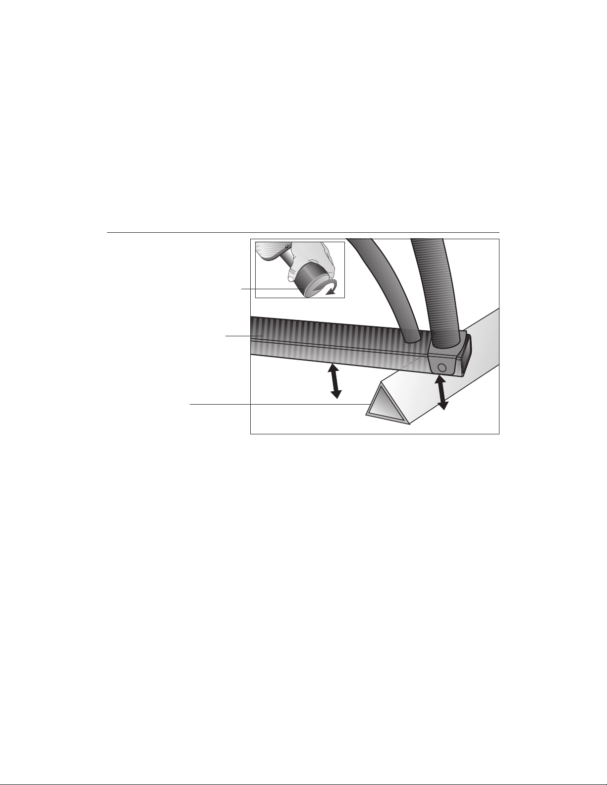
Diagram 17
page 20
• Turn the height adjustor clockwise to raise the height of the front end.
• Turn the height adjustor counterclockwise to lower the height.
Once you have the proper height adjustment, use the wrench to turn the
nut counterclockwise and tighten it securely against the base tube.
Clean the ramp.
Foot pedal
Ramp
Wipe ramp with a
damp, clean cloth.
Roller
23. Clean the ramp. Diagram 17. Wipe down the ramp and foot pedals with a
soft cloth dampened in a diluted solution of mild soap and water.
Page 21

COMMERCIAL PRODUCTS DIVISION
Diagram 18
Insert the front
end cap.
Upright support
Front end cap
CAUTION: If you purchased the POLAR® chest strap option, be sure to test
the heart rate display (refer to page 22) prior to inserting the front end cap.
24. Once you have checked that the heart rate feature is working properly, insert the
front end cap (found in the Hardware kit) into the base assembly. See Diagram 18.
Insert the front end cap into the base tube. Make sure that the cable does not get
pinched by the end cap. If necessary, use a rubber mallet to secure the end cap.
REMOVING THE LOCKING PIN
CAUTION: Do not allow children on the EFX. Be aware that injuries can
occur from the roller arm and handlebar movement. Always use the locking
pin to secure the roller arm when the EFX is not in use.
Diagram 19
EFX Locking pin.
Insert the locking
pin when you are
finished working
out or when you
leave the EFX for
an extended
length of time.
Storage location
The locking pin secures the roller arm and keeps it from traveling up or down the
ramp. Pull firmly on the pin to slide it out of the ramp. A lanyard is attached to the
locking pin and ramp. Refer to Diagram 19.
Store the locking pin underneath the ramp once it is removed from the roller arm.
See inset in Diagram 19.
page 21
Page 22

COMMERCIAL PRODUCTS DIVISION
SUPPLYING POWER TO THE EFX534
The EFX does not require an electrical power connection. It has an internal battery
that is recharged every time a user works out for a reasonable period of time. A
pedaling speed above 40 strides per minute must be maintained for several seconds
before the Precor banner appears on the display. Once the banner appears, the user
can press QuickStart or Enter to begin working out. For more information, refer to
page 34,
Exercising on the EFX
.
TESTING THE HEART RATE DISPLAY
If you have purchased the optional POLAR® chest strap, verify that the heart rate
display is operational before customers begin using the machine.
Note: To conduct electrical impulses from a user’s heart, the electrode strips on
the chest strap must be in contact with the user’s skin. Usually, the concentration
of salts in a person’s perspiration provides enough conductivity to transmit a
signal to the receiver in the display console. However some people, because of
body chemistry or erratic heart beats cannot use the heart rate feature on the
EFX. To purchase a POLAR® chest strap, refer to
Obtaining Service
on page 7.
Diagram 20
Wearing the POLAR
chest strap.
POLAR® chest strap
positioned and
centered on chest.
POLAR® chest strap
electrode strips
Dampen with water.
®
1. Wet the electrode strips on the POLAR® chest strap and wrap it around your
chest as shown in Diagram 20. Adjust the strap so that it maintains a snug fit.
2. Hold onto the stationary handrail and step onto the foot pedals.
3. Begin pedaling and maintain a stride rate above 40 strides per minute. The
Precor banner will appear on the display.
4. Wait five to ten seconds. A number indicating your heart rate (beats per minute)
should appear in the display. Three dashes appear (— — —) if a heart beat is
detected, but interference is occurring. Try readjusting the chest strap.
5. If the heart rate display appears, the cables are properly connected and the
heart rate feature can be a viable part of a user’s workout.
6. If the heart rate display does not appear, press Reset to return to the Precor
banner and then, ask someone else to try steps 2 through 4. If no heart rate
number appears, reconnect the cables at the front of the base tube. Follow
steps 1 through 4, again.
page 22
If a heart rate cannot be detected, refer to
Obtaining Service
on page 7.
Page 23

COMMERCIAL PRODUCTS DIVISION
Custom Settings Mode
These next few pages provide information that lets you customize the EFX. It is
not information that your customer needs to see. This section covers the following
information about how to:
• determine which unit of measure appears on the display
• set maximum workout and pause times
• display the odometer and other useful information
• connect to CSAFE compatible devices
Note: If your customers are interested in the learning more about the EFX, you may
wish to direct them to the manual available on Precor’s web site (www.precor.com).
(The manual that appears on the web site does not contain the information found in
this section.)
Diagram 21
Display console keys used for Custom Settings Mode.
The RESET key initiates the Custom Settings Mode.
To continue, press the next key within 1/3 second.
Gently, press and hold any
available selections.
▲▼
key to view the
CHANGING THE CUSTOM SETTINGS
The “custom” settings are accessed through specific codes that help eliminate
unauthorized access. Refer to Diagram 21 to locate the keys. Information that you
can access and features that can be customized are as follows:
• Units of Measure — Select between U.S. Standard and Metric displays.
• Maximum Workout Time — Sets a maximum limit on workout time. Note
that an additional five minute cool-down period is appended to a completed
course, so adjust the maximum time limit accordingly.
• Maximum Pause Time — Sets the maximum duration for which a person
can “pause” his or her workout. Note that Pause time limits are only effective
when the EFX is powered by the optional battery recharger.
• Odometer, Hours of Use, Software Version, and Error Log —The EFX stores
the cumulative strides, the number of hours that the unit has been in use, the
software version and software type (which is valuable when calling Customer
Support), and an error log (useful when troubleshooting).
Accepts displayed data and moves
to next aspect of the program.
page 23
Page 24

COMMERCIAL PRODUCTS DIVISION
To access the Custom Settings Mode, the following must occur:
❑ Electrical power must be supplied.
The foot pedal speed must be maintained at 40 strides per minute. Or, the
optional battery recharger must be plugged into the EFX and connected to an
appropriate power source.
Note: The optional battery recharger connection is highly recommended, if
you plan to customize the EFX.
❑ Check that the Precor banner appears on the display and, if necessary,
maintain the minimum stride rate.
❑ Press the appropriate key sequences.
To select the units of measure and set the maximum workout and pause times,
press the following:
Note: The Resistance ▲ key in the following series is the key on the left as you face the
display. If you press the Resistance ▼▲ keys on the right, you cannot access the
Custom Settings.
Reset, QuickStart, Enter, QuickStart, Resistance ▲, QuickStart, Enter, QuickStart
Important: To access Custom Settings Mode, press Reset while the Precor banner
is displayed. Within 1/3 second, begin pressing the key sequences. If the system
does not detect a key press (within 1/3 second after Reset), it returns to the banner.
Once you begin entering a key sequence, each key must be pressed within four
seconds of the other or the Precor banner reappears and you have to begin again.
The functions of the display console keys while in Custom Settings Mode are
described in the box below.
Display key functions within the Custom Settings Mode
▼▲ lets you scroll through the
various selections that appear.
Enter saves the information being
displayed and moves to the
next aspect of the program.
Reset exits Custom Settings Mode and
Select displays the name of the data
Note: The ▼▲ keys can be gently pressed and held to view several selections.
The longer the key is held down, the faster the numbers scroll past.
DETERMINING THE UNITS OF MEASURE
displays the Precor banner.
field that you are viewing. Or,
toggles between the available
selections.
page 24
Two different units of measure can be selected,
Metric
or
U.S. standard
. Make your
selection using the ▼▲ keys. Press Enter once the correct unit is displayed.
Note: Anytime you wish to exit the Custom Settings Mode, press the Reset key. Any
previous display attributes that you selected by pressing Enter are saved and recorded in memory. If no key press is detected within two minutes (when the optional
battery recharger is attached), the system resets and the Precor banner reappears.
Page 25

COMMERCIAL PRODUCTS DIVISION
SETTING A WORKOUT TIME LIMIT
You can limit how long a user works out by setting a duration between 1 and 240
minutes. You can also choose NO LIMIT which allows the user to select a course and
work out indefinitely.
Note: The QuickStart program is automatically set at the custom settings limit.
Use the ▼▲ keys to select a workout time limit. For example, if you set the workout
time limit to 20 minutes, the EFX allows users to specify a workout between 1 and 20
minutes. Users would not be allowed to specify a time longer than 20 minutes. Take
into account that the user will get an additional five minute, cool-down period
appended to his or her workout, so adjust the time limit accordingly.
SETTING A PAUSE TIME LIMIT
Use the ▼▲ keys to set a Pause time limit between 1 and 120 seconds (two minutes).
Important: Changes to the Pause time become effective only when the power
source for the EFX is the optional battery recharger. If no battery recharger is
connected and the stride rate drops below 40 strides per minute, the EFX moves
into its thirty second shut down mode. Refer to page 31.
VIEWING THE ODOMETER, HOURS OF USE, SOFTWARE
VERSION AND ERROR LOG
The display console keys that you need to press to view the odometer, the number of hours the EFX has been in use, the software version and any error codes,
are as follows:
Reset, Enter, QuickStart
Important: Remember to begin at the Precor banner. After pressing Reset, the
next key in the sequence must be pressed within 1/3 second.
The numbers 6, 5 appear on the display as you press the associated key.
The field name Odometer appears briefly and then the odometer value (the cumulative
strides users have travelled) appears. When the Select key is pressed the word STRIDES
appears on the display indicating that the odometer value equals the total strides
logged by the EFX. When the key is released, the odometer value reappears.
Press Enter and the number of hours that the unit has been in use appears. The EFX
notes the passing of minutes, but the numeric value that appears is truncated to the
nearest full hour. When the Select key is pressed the word HOURS appears on the
display. When the key is released, the numeric value reappears.
Press Enter again and the unit’s three digit SW Version (upper board software
version number) appears on the display.
Press a Select key to view the lower board's version number. The Select key
toggles between the upper and lower board’s version numbers.
page 25
Page 26

COMMERCIAL PRODUCTS DIVISION
Press Enter once again and the Error Log appears. The EFX stores the last ten
errors that have been detected. Press any ▼ or ▲ key to view the error codes.
Note: If the EFX has no errors stored in memory, a “– – –” appears on the display.
To view the odometer reading at the time the error was detected and the hours of use
at the time the error occurred, press the Select key while the error code is being
displayed. The Select key acts as a toggle between the associated information.
To clear (delete) the error log, press QuickStart for at least four seconds while
viewing the list. Prompts appear on the display and confirm (OK) that the error
messages have been deleted (“cleared”) from memory.
Important: You cannot retrieve the error log once you have deleted it.
USING CSAFE STANDARD EQUIPMENT
The EFX is fully compatible with CSAFE protocols. Once the unit is connected to
a CSAFE master device and the user maintains a stride rate above 40 strides per
minute, he or she is prompted to enter an identification number (user ID).
Note: If the optional battery recharger is plugged into the EFX and connected to
an appropriate power source, then no pedaling is necessary for user ID entry.
Five zeros appear on the display. The left zero indicates that it is awaiting input.
The following table provides information about the keypad functions:
User ID Entry: Program Keys
▼ or ▲ moves the blinking LED from field to field.
Enter submits the displayed user ID. Note that if the five zeros
are being displayed when the user presses Enter, the user
ID entry is bypassed and the Course prompt appears.
Reset resets the display to the Precor banner.
A message indicates when the user ID is accepted by the CSAFE master device.
Then, the course prompt is displayed. See
Quick Steps to Working Out
on page 37.
Note: If the user’s stride rate drops below 40 strides per minute while using the
CSAFE device connection, a prompt PEDAL FASTER appears. If the stride rate
remains below the 40 strides per minute threshold for the next twenty seconds,
the CSAFE connection is terminated. The word RESETTING appears on the
display while the EFX disconnects from the CSAFE device.
page 26
To review information about CSAFE specifications, visit the web site at:
www.fitlinxx.com/csafe
Note: The EFX supports the CSAFE master device per the specifications found
at the web site. However, exceptions do exist. If you have questions or need
technical support, refer to
Obtaining Service
on page 7.
Page 27

COMMERCIAL PRODUCTS DIVISION
The EFX®534 Display
The EFX is designed so users can work out with minimal instruction or training. The
directions on the console and the prompts on the display will guide a user through the
entire workout session. Before the EFX is used, however, we recommend that you
familiarize yourself with it so you can instruct your customers to use it safely and
effectively. This section covers the following information:
• an overview of the features provided on the display console
• an explanation about the available courses
• instructions for utilizing the heart rate options
FEATURES ON THE DISPLAY CONSOLE
As a user exercises, the display console provides motivation by presenting
constant feedback about his or her progress. An brief explanation of each feature
on the display console appears in Diagram 22. Look on the following pages for a
more thorough explanation.
Diagram 22
SmartRate® display
During course
selection, the
course name
appears here.
EFX Display Console
CENTER DISPLAY
During a workout, the SELECT keys highlight
which workout statistics appear on the display.
If a heart rate is detected, it
played in this window.
Banner, prompts, workout s
and course profile appear i
Center display.
Keypad is used to
input or select data
and control the
workout session.
Note: If an error message should appear, call a Precor qualified service technician or service center. Refer to
Obtaining Service
, on page 7.
page 27
Page 28

COMMERCIAL PRODUCTS DIVISION
USER SETUP PROMPTS
Precor banner: The Precor banner and course profiles appear in the center display. Always start a workout at the Precor banner.
Important: Because the EFX is self-powered, the Precor banner does not appear
until the user maintains a stride rate above 40 strides per minute. Note that there
is an exception to this rule. If power is being supplied through the optional battery
recharger, then pedaling is not required prior to entering a course. Refer to page 7,
EFX® Self-powered Features.
Setup prompts appear in the center display prior to your workout. You address
each prompt using the keypad keys.
Keypad use during
Setup Prompts Description
▼ or ▲ Scrolls through the selections. The longer the key is held
down, the faster the selections scroll past.
Select Acts the same as the Enter key.
Reset Exits the Setup Mode and returns the display to the
Precor banner.
QuickStart Bypasses any remaining Setup prompts and accesses
the course selection. Refer to
the Setup Prompts
on the opposite page.
Using QuickStart During
Enter Submits the displayed selection and moves onto the next
Setup prompt.
COURSE prompt: The EFX provides 5 course selections. The first course selection
to appear on the display is MANL (Manual course). Use any ▼▲ key to change the
selection. Press Enter to accept the displayed name. Have the user refer to the
display label on the console to determine which abbreviations represent the different course selections. For a description of the courses, refer to page 40.
Important: If you press QuickStart while a course selection is displayed, the
course begins. Refer to
Using QUICKSTART during the Setup Prompts
.
Note: If no key press is detected for ten seconds, the display prompts the user on
what to do next. If no key press is detected for two minutes or the RESET key is
pressed, the display returns to the banner.
page 28
Workout Time prompt: A default value of 30 minutes (or the custom settings
limit, whichever is less) appears. Use any ▼▲ key to change the workout time.
For MANL, XTR, and INTV courses, the workout time may be set as low as one
minute or as high as the custom settings limit. Press Enter or QuickStart to
accept the displayed value.
Page 29

COMMERCIAL PRODUCTS DIVISION
Weight prompt: A default weight (WGT: 150 lb. or 68 kg.) appears. Use any ▼▲
key to change the weight between 1 or 999 pounds. An accurate weight entry
provides for a more accurate calorie count and proper use of the Weight Loss
course. Press Enter to accept the displayed value.
Age prompt: At the AGE: 0 prompt, use any ▼▲ key to display the user’s age
(from 1 to 99). Press Enter to accept the displayed value. Note that SmartRate
does not appear unless an age value above zero is entered.
USING QUICKSTARTTM DURING THE SETUP PROMPTS
The QuickStart key can be pressed any time during the Setup prompts. Default
values apply after that point. Refer to QUICKSTART on page 33.
Press QUICKSTART at the... The following occurs:
Precor banner The user bypasses the Setup prompts and be-
gins working out in the Manual course.
Course prompt The displayed course is accessed.
Note: Since a default workout time is accessed,
no progress message such as, “10% complete”
will appear on the display. The exception to this
rule is the Weight Loss Course.
Time prompt The time that appears on the display becomes
the workout time limit. It may be set to any value
from 1 to the custom settings limit. If NO LIMIT
is selected in the
page 23), a user can select INFINITE once he or
she passes 240 minutes by pressing the ▲ key.
Custom Settings Mode
®
(see
Weight prompt The weight that appears on the display becomes
the designated weight that the EFX uses to
compute statistics. Acceptable entries are
between 1 and 999.
Age prompt The age that appears on the display becomes
the designated age that the EFX uses to compute statistics. A correct age entry between 1 and
99 is very important if the user’s plan to utilize
the heart rate features of the EFX. The Quick-
Start key acts the same as the Enter key at
this point because the user has answered all the
Setup prompts.
page 29
Page 30

COMMERCIAL PRODUCTS DIVISION
CENTER DISPLAY
The items that appear in the display during a workout are described below.
Workout Statistics: Eight items, that relate to the workout, can appear on the
display once a user begins a course. After entering a course, the workout time
and the course profile appear for several seconds. Indicator lights appear so that
the user knows what information is being displayed. The Select keys can be used
to change what workout statistics appear on the display. Refer to page 35, for
more information.
TIME: During a workout, the time (0:00) display appears when a user begins a
course. Workout time appears in minutes and seconds. However, should a user
exceed 60 minutes (during a single workout), the workout time display converts
to hours and minutes.
STRIDES: Shows the total number of strides completed. The number will always
be even since two strides create one complete revolution of the flywheel. A stride is
an exaggerated walking movement. On the EFX, if a user starts in a position with
one foot forward and one foot back, a stride is completed when he or she moves
the rear foot all the way forward while the forward foot moves to the rear.
STRIDES PER MINUTE: Displays the number of strides completed in one minute
(i.e., the user’s current pedaling speed).
CALORIES: Provides the cumulative number of calories being burned. The calorie
calculation is dependent on the weight that is entered during the setup prompts.
An accurate weight selection results in a more accurate calorie count.
Course Profile: During a workout, the course profile appears in the right portion
of the display and corresponds to the program that the user selected. As the user
proceeds through his or her workout, the course position is indicated by a blinking
column.
The height of the column in the course profile represents the resistance settings.
Each row represents three levels of resistance. When the lowest row of LED’s is lit,
the user has selected a resistance level between 1 and 3, the next row represents
levels 4 through 6, and so on. If SmartRate
®
is displayed, then the two columns on
the right are not used by the profile display.
CALORIES PER MINUTE: Indicates the approximate number of calories being
burned per minute.
WATTS: Indicates the amount of energy the EFX is currently generating and is
derived from the current resistance and pedaling speed.
METS: Displays the metabolic equivalents of the user’s current energy expenditure
level. A MET’s level of 1 represents the body at rest. Note that when a user stops
pedaling, the MET’s value drops to zero because the displayed information no
longer corresponds to the user’s MET’s level.
page 30
Resistance Level: Indicates the degree of effort (1 through 20) associated with
the foot pedal resistance. This display only appears when a user presses the
Resistance ▼▲ keys. Refer to page 32, Resistance ▼▲ keys.
Page 31

COMMERCIAL PRODUCTS DIVISION
SMARTRATE® DISPLAY
SmartRate®: A user must enter an age, during the course Setup prompts and wear a
POLAR® chest strap, while in a course program, before the blinking segment in the
bar graph can show the zone that his or her heart rate is in. Refer to page 35,
Utilizing the SmartRate® Feature
.
Important: During a course, the stride rate must be above 40 strides per minute
and a user’s heart rate must be above 40 beats per minute before the SmartRate
segment begins to blink.
HEART RATE: The heart rate display lets a user monitor his or her heart rate. When
a heart beat is detected, the number appears in the small upper right display (refer to
Diagram 22). If the user does not wear a POLAR® chest strap, a heart rate will not be
detected and no pulse rate appears. Refer to
The Heart Rate Feature
INFORMATIONAL DISPLAYS PRIOR TO SHUTDOWN
The EFX saves its battery charge by moving into a shutdown mode. Whenever
PEDAL FASTER appears on the display, the heart rate, SmartRate® and course
indicators turn off. If the user does not maintain a stride rate of 40 strides per
minute, then a thirty second shut down process begins.
Shortly after the thirty second shut down process begins and the PEDAL FASTER
prompt does not induce anyone to increase the pedaling speed, the display appears
blank and all key presses are ignored, except Reset. After several seconds, dots
appear on the display indicating that the EFX is shutting down. If no pedaling is
detected, the EFX eventually turns off.
If the EFX is connected to a CSAFE master device, a slightly different scenario
occurs. When the number of seconds remaining before the EFX shuts off equals
ten seconds (instead of eight), the workout session ends. RESETTING appears
in the display while the EFX disconnects from the CSAFE master device. All key
presses are ignored. Pedaling has no effect on the display.
®
on page 35.
Low Battery
If the battery voltage is low or needs recharging, the words WARNING - LOW
BATTERY appear after the PRECOR banner. The EFX continues to function even
with a low battery, but user and course information is lost once the user stops
pedaling. Note that the Pause feature does not work.
page 31
Page 32

COMMERCIAL PRODUCTS DIVISION
KEYS ON THE DISPLAY CONSOLE
The Precor products have an easy-to-use keypad that is activated by the slightest
touch. Remind users that they only need to lightly tap the keys.
Each key on the display console’s keypad provides specific functions. The ▼▲
keys let the user enter data in answer to the display prompts and change the
resistance during a workout.
Diagram 23
Display console keypad.
During a workout, the SELECT
QuickStart: Bypasses the
remaining Setup prompts and
enters the Manual course.
Exit and
return to
banner.
keys highlight which workout
statistics appear on the display.
During the Setup
prompts, accepts
displayed data and
moves to next
prompt.
Gently, press
and hold the
or ▲
change the
resistance level.
▼
keys to
The following information explains the different uses of the keys from left to right.
To locate each key, look at the display console or refer to Diagram 23.
RESISTANCE
▼▲▼▲
▼▲: During a workout, the Resistance ▼▲ keys let the user de-
▼▲▼▲
crease or increase the force applied against his or her stride. The display can
show a range from 1 to 20. Setting #1 provides the least resistance. A user can
review the EFX’s resistance any time during a workout, by lightly touching either
Resistance ▼ or ▲
key. He or she can opt to change the resistance, by holding
the key down for more than two seconds.
page 32
Note: The RESISTANCE
▼▲▼▲
▼▲ keys appears on both ends of the display label for
▼▲▼▲
the user’s convenience.
When a user changes the resistance by pressing the Resistance ▼ or ▲ key, the
number that appears on the display shows the
target
resistance (not necessarily,
the present resistance being applied) because the display can change much faster.
The height of the course profile reflects the resistance levels. Each row that is lit
represents three levels of resistance. When the first row is lit, the resistance is
set between 1 and 3. If the first two rows are lit, the selected resistance level is
between 4 and 6, and so on.
Page 33

COMMERCIAL PRODUCTS DIVISION
SELECT keys: While the Precor banner is displayed, the SELECT keys act the
same as the Enter key. During a course, the Select keys change what items
appear on the display. Refer to page 36,
SELECT Key
.
Changing the Display Features Using the
RESET: While answering the Setup prompts or during a workout, a user can cancel
the course program, clear the display, and return to the banner by pressing Reset.
QUICKSTART: QuickStart lets the user bypass the Setup prompts and start a
workout immediately using the Manual course.
Default values apply.
QUICKSTART Default Values
Prompts Default Value
COURSE Manual
XX MIN Custom settings limit. Refer to page 23. Note that the Weight
Loss course is fixed at 28 minutes and the Hill Climb course
is set at 30 minutes.
WEIGHT 150 lbs. (68 kg.)
AGE 0 : A valid Age must be entered to utilize the SmartRate
display. If QuickStart is pressed
after
the age prompt appears,
®
then the SmartRate® display will appear when the user wears
the POLAR® chest strap. If no age entry occurs, the
SmartRate® display lights up, but no blinking sensor appears.
ENTER: Workout specific prompts need to be answered and “entered” into memory.
Pressing Enter selects the information being displayed and processes it.
page 33
Page 34

COMMERCIAL PRODUCTS DIVISION
Exercising on the EFX
The EFX is designed so that a user can work out with minimal instruction. The
directions on the console and the prompts on the display help guide the user
through an entire workout session.
This section provides workout tips and information about:
• using the heart rate features • quick steps to working out
• safety features • cooling down after a workout
• using the handlebars • pause and exit features
CAUTION: Before beginning any fitness program, make sure that all users
receive a complete physical examination from their physician.
THE HEART RATE FEATURE
If a user wishes to view his or her heart rate on the display, tell them to wear the
POLAR® chest strap while working out. A heart rate signal is transmitted to the
receiver installed in the display console. During a workout, the heart rate indicator
lights, begins blinking and then, displays the heart rate. This lets the user see what
his or her heart rate is doing even when the display is presenting other workout
statistics. For more information, refer to page 22,
®
Testing the Heart Rate Display
.
UTILIZING THE SMARTRATE
Add the benefit of SmartRate® to every course on the EFX. Using SmartRate® as a
visual cue helps the user adjust his or her exercise routine to suit specific needs.
SmartRate® simplifies the correlation between heart rate and exercise. A user doesn’t
have to stop concentrating on the workout to find his or her pulse. It appears on the
display along with the SmartRate® zone. Once a user begins a course, a blinking
segment in the bar graph appears on the right of the display (if you entered your age
during the Setup prompts). The blinking segment indicates the zone that a user’s
heart rate is in: Weight Loss or Cardiovascular.
Important: Access to SmartRate® is only available when the person exercising
wears a POLAR® chest strap. (The POLAR® chest strap is a separate purchase
option.) The SmartRate® indicator lights do not appear when QuickStart is used
to select a course.
Weight Loss Zone
For the ideal “weight loss” range, a user’s heart rate should be between 55% and
70% of his or her maximum aerobic heart rate. It should never exceed 80% of the
user’s maximum aerobic heart rate or go above a user’s training zone. Refer to
Diagram 26 on page 41 for the appropriate training zone.
Cardiovascular Zone
When a user maintains a heart rate between 70% and 80% of his or her maximum
aerobic heart rate, he or she is improving his or her overall cardiovascular/cardiorespiratory fitness level. Maintaining a heart rate in either zone (weight loss or
cardiovascular) for 30 minutes or more on a regular basis (minimum three times a
week) provides the greatest benefits.
®
FEATURE
page 34
Page 35

COMMERCIAL PRODUCTS DIVISION
Diagram 24
EFX Locking pin.
Insert the locking
pin when you are
finished working
out or when you
leave the EFX for
an extended
length of time.
Storage location
REMOVING THE LOCKING PIN
The locking pin secures the roller arm and keeps it from traveling up or down the
ramp. Pull firmly on the pin to slide it out of the ramp. A lanyard is attached to the
locking pin and ramp.
Store the locking pin underneath the ramp once it is removed from the roller arm.
See inset in Diagram 24.
Note: The following text is written in second person so that you, as owner or
manager, can copy the sections (excluding
Maintenance
) for your customers.
WORKOUT TIPS
The steps to working out on the EFX are listed on the next page. A short description
appears in the left margin with the more thorough explanation following on the right.
Tips to consider during your workout are shown below:
• If the optional battery recharger is not connected, you need to maintain a
stride rate above 40 strides per minute before keypad entries can occur. If
you have questions, talk to the manager.
• Remove the locking pin. Refer to page 35.
• Answer the Setup prompts by pressing the ▼ or ▲ keys.
• Press Enter to select the information being displayed.
• The workout time prompt lets you choose between and 1 to 240 minutes. If
the custom settings allow it, you can also select an indefinite workout time
by pressing the ▲ key, until the word INFINITE appears on the display.
• During a workout, the Select keys determine which workout statistics appear
on the display.
page 35
Page 36

COMMERCIAL PRODUCTS DIVISION
Diagram 25
Using the EFX handlebars.
Handlebar
Water bottle holder
Stationary handrail
USING THE HANDLEBARS
The handlebars on the EFX provide an upper-body workout that, when used properly,
helps increase cardiovascular fitness. By adding the upper-body movement to your
cross training workout, you’re actually increasing your work effort and enhancing your
overall fitness level. A variety of hand positions can intensify the effectiveness of
your workout. Ask staff personnel for additional information.
USING THE STATIONARY HANDRAIL
Always grasp the stationary handrail to help keep your balance when you step on
to or off of the foot pedals and when you use the display keys. During a workout,
use the stationary handrail to rest or slow down your upper-body movement.
CHANGING THE DISPLAY FEATURES USING THE SELECT KEY
The Select keys let you choose which feature(s) appears on the display. When
you enter a course, the workout time and course profile features are preselected
for you. As you work out, TIME indicates the amount of time you've spent in your
work out (or the time remaining). The blinking column in the course profile indicates progress along the course.
Each Select key affects four different display features. The left SELECT key,
causes the indicator light to appear next to TIME, STRIDES, STRIDES PER
MINUTE and CALORIES. The right SELECT key, highlights COURSE PROFILE,
CALORIES PER MINUTE, WATTS and METS.
You can determine which features appear by turning the indicator lights, next to the
item, on or off. If the indicator light is off, the item will not appear in the display.
page 36
Page 37

COMMERCIAL PRODUCTS DIVISION
QUICK STEPS TO WORKING OUT
Important: If BATTERY LOW appears on the display anytime during a workout, contact the staff
personnel. Pay attention to the words, PEDAL FASTER. The EFX is warning you that you need to
pedal faster to avoid disconnecting the battery, which is the power source for the EFX display.
1
Use the Heart Rate
features.
2
Step into the foot
pedals and select a
course.
Important: When you begin
moving the foot pedals,
continue to hold onto a
handrail with one hand while
you answer the Setup
prompts with the other.
3
Continue your
workout until course
completion.
1. For your Heart Rate to appear on the display, you need to
wear a POLAR® chest strap.
CAUTION: Hold onto the stationary handrail while you
step into the foot pedals and whenever you reach out
to press the keypad.
2. Begin pedaling and follow the display prompts. Make a
COURSE selection and enter your workout time, weight
and age.
Note: To answer the Setup prompts, use the ▼▲ keys. Press
Enter to select the information being displayed. See Workout
Tips on page 35. The five available courses appear on the
label attached to the display console. Brief course descriptions are also provided beginning on page 40.
To pause during your workout session, stop pedaling for a
few seconds. Be aware that if the optional battery recharger
is not attached, you have only thirty seconds before the
EFX shuts off. See
Pause, Cool Down and Exit Features
3. When you have completed a course that has a limited duration, a five minute, cool-down period automatically begins.
Hold onto the handrail while the EFX reduces the resistance
by 20 percent. Note that you can always exit a course prematurely using the Reset key.
Note: Not all courses supply the cool-down period. See
Cooling Down After Your Workout
on the next page.
.
4
End your workout and
review your workout
statistics.
Important: Continue
pedaling while reviewing
your workout statistics.
5
Stop pedaling and hold
on to a handrail while
you step off the EFX.
4. After you complete the five minute, cool-down period (or exit a
course prematurely using Reset), the Workout Summary ban-
ner appears. If you wore a POLAR® chest strap during your
workout, a heart rate analysis follows the banner and displays:
• the average heart rate during your workout
• the maximum heart rate during your workout
• the duration that your heart rate was in the Weight Loss
or Cardiovascular zones.
Workout statistics except TIME, STRIDES and CALORIES
reset to zero. (TIME shows the accumulated workout time
including warm-up and cool-down periods.)
5. When you are finished reviewing your workout statistics,
stop pedaling. Hold on to the stationary handrails while
you carefully step down from the EFX.
page 37
Page 38

COMMERCIAL PRODUCTS DIVISION
COOLING DOWN AFTER A WORKOUT
Cooling down is an important aspect of your workout because it helps reduce muscle
stiffness and soreness by transporting excess lactic acid out of the working muscles.
It also helps provide a smooth transition that allows your heart rate to return to its
normal (non-exercising) state. The EFX automatically initiates a five minute, cooldown period once you complete a course that has a specified time duration. A prompt
appears, indicating that you are in cool down.
During your cool down, the workout statistics continue to appear. When you complete
the five minute cool down, a Workout Summary appears. See the information below.
Important: To activate a cool-down period, a course must “end.” The course ends
when the workout time (entered during the Setup prompts) expires. If you chose
INFINITE, no cool-down period is appended to the course.
PAUSE, COOL DOWN AND EXIT FEATURES
Pausing, cooling down, and exiting are integral parts of your workout and can be
accessed any time during a course. The EFX goes through several prerequisites
before actually exiting a course. The following tables explain the various situations.
Since the EFX is self-powered, foot pedal movement must be continuous to avoid
shut down. For more information, refer to page 31.
Note: If the optional battery recharger is supplying power to the EFX, the factory
setting for Pause mode is two minutes (120 seconds). The business owner or
manager has the option to change the setting. A duration can be set between 1 and
120 seconds and limits how long a user can pause his or her workout. Refer to
Custom Settings Mode
on page 23.
In a course, This is what happens...,
you complete it Enter Cool Down. At the start of the cool-down period, the resis-
tance is reduced by 20 percent. You can adjust the setting using
the Resistance ▼▲ keys. The display features remain, so you
can press the Select keys to view your workout statistics.
Note: A cool-down period is appended to those courses that
have a finite duration. If you do not enter a workout time during
the Setup prompts, or you select INFINITE, then a cool-down
period does not occur when you reach the end of a course.
you press Reset Enter the Workout Summary mode. You can scan through
the workout statistics by pressing the Select keys. Note that
the TIME display shows the accumulated workout time including warm-up and cool down periods.
no pedaling
or slow pedaling
is detected Enter Pause mode. PEDAL FASTER appears on the display
and workout time stops accruing. For more information, refer
to page 31.
page 38
Page 39

COMMERCIAL PRODUCTS DIVISION
In Pause
mode, you This is what happens...,
resume pedaling Returns to the course and the workout statistics continue from
where you left off.
press Reset Displays the Workout Summary banner.
exceed time limit The EFX exits Pause mode, resets the displays, and turns off.
In Cool down
mode, This is what happens...,
no pedaling
or slow pedaling
is detected Enter Cool down, Pause mode. Workout time stops accruing
and PEDAL FASTER appears on the display. If you enter Pause
mode, it is of limited duration. Check with staff personnel or
refer to
Displays Prior to Shutdown
Custom Settings Mode
on page 31.
on page 23 and
Informational
you press Reset Displays the Workout Summary banner. See Reset on the
previous page.
it ends. Displays the Workout Summary banner.
At the Workout
Summary
banner, you This is what happens,...
press Reset The workout statistics are reset to zero and the EFX shuts off.
INSERTING THE LOCKING PIN
To secure the EFX after your workout, take the following steps:
1. Locate the locking pin in its storage location under the ramp. Refer to
Diagram 24 on page 35.
2. Remove the locking pin from its stored location and insert it into the roller
arm. Position the locking pin so that you insert it from the outside edge of the
ramp toward the inside edge.
3. Firmly slide the locking pin through the holes in the roller arm. Be sure that the
locking pin is all the way through roller arm. Refer to Diagram 24 on page 35.
Gently move the roller arm to make sure that it is secure.
page 39
Page 40

COMMERCIAL PRODUCTS DIVISION
Courses
The EFX lets the user choose between five variable courses. This section provides
information about the special features and functions of the EFX courses and how to
best utilize the:
• Manual course • Cross Training course
• Hill Climb course • Weight Loss course
• Interval course
Note: To choose a course, begin pedaling. Once the Precor banner appears, press
Enter. User-friendly prompts guide you through the course selections. Refer to
Quick Steps to Working Out
MANUAL MODE AND THE QUICKSTARTTM KEY
Manual mode lets you set the resistance level. As with other courses, when you
complete the time limit set for the course, the automatic cool-down period begins.
You can choose Manual mode in two different ways:
on page 37.
• pressing the QuickStart key at the Precor banner. QuickStart bypasses the
remaining selections and starts the Manual course. Default values
include a time limit of 30 minutes (or the custom settings, whichever is
less), 150 lbs. (68 kg.) and an age of zero. The SmartRate® display is inactive.
• pressing Enter at the Precor banner. This causes the EFX to display several
Setup prompts. At the COURSE prompt, select MANL.
The Manual course profile initially appears as a flat line. Use the ▼▲ keys to adjust
the resistance level. (See page 32 for more information.) As you proceed with your
workout, a blinking column represents your position on the course.
HILL CLIMB COURSE
For your convenience, the resistance in the Hill Climb course is preset. Review
the display label to ascertain the ascent and descent you’ll be feeling in the pedal
resistance throughout the course. Anytime during the workout, you can override
the resistance settings by pressing the Resistance ▼▲ keys.
INTERVAL COURSE
The interval course on the EFX lets you select the rest and work intervals according
to your training regimen. You set the resistance level for first rest and work interval
and the software repeats the intervals throughout the course. At any point during the
workout, you can change the settings of the current interval by simply pressing the
▼▲ keys. The software remembers the new settings and applies it to the appropriate
rest or work interval.
page 40
Page 41

COMMERCIAL PRODUCTS DIVISION
Diagram 26
Target Zones
HEART RATE TARGET ZONES
200
190
180
170
YOUR HEART RATE
160
150
140
130
120
100
RECOMMENDED CARDIOVASCULAR ZONE
RECOMMENDED WEIGHT LOSS ZONE
90
80
70
25 30 35 40 45 50 55 60 65 70 75
20
MAX.
HEART
RATE
Cardio
Zone
Weight
Loss
Zone
YOUR AGE
Important: If you entered your age during the Setup prompts and are wearing the
POLAR® chest strap, you can adjust the rest or work intervals to keep your heart rate
in its recommended zone. For the weight loss zone, try to maintain your heart rate at
the lower end (55% of maximum heart rate) while in the “rest” intervals and keep it at
70% of maximum heart rate while in the “work” intervals. See Diagram 26.
To use the interval course, take the following steps:
1. Follow the instructions on page 37,
Quick Steps to Working Out
.
2. At the COURSE prompt, use the ▼▲ key to select the INTV course.
3. Press Enter.
4. Select a workout time. If the workout time entered is an even number, then
all intervals (rest and work) are two minutes long. If the workout time that you
enter is an odd number, then all intervals (rest and work) are two minutes
long, except the last one which will be one minute.
5. Press Enter to proceed to the next prompt. When you’re finished answering
the Setup prompts, the Interval course begins.
To set the resistance level for each interval, take the following steps:
1. When the Rest interval prompt appears, press the Resistance ▼ or ▲ key to
change the resistance level. When the desired setting is displayed, simply
continue working out—you do not need to press Enter.
The EFX returns to the “rest” settings at the beginning of each rest interval
until you readjust it or end your workout.
2. The same procedure applies to specifying the settings for the work interval.
Each time the EFX changes intervals, it informs you by displaying a message. When
you complete the time limit set for the course, the automatic cool-down period begins.
page 41
Page 42

COMMERCIAL PRODUCTS DIVISION
CROSS TRAINING COURSE
The Cross Training course consists of alternating segments of forward and backward
pedaling movements that focus on working the thigh and calf muscle groups. Ask staff
personnel about the benefits of this type of workout.
The course profile is divided into one minute intervals. Prompts appear on the display
indicating when you should change the pedaling direction. Similar to the Interval
course, changes to the pedal resistance can be made at any time by pressing the
Resistance ▲▼ keys.
To use the Cross Training course, follow the steps found in
Out
on page 37. When the COURSE prompt appears, choose XTR.
Once you set the resistance level for a forward or backward pedaling interval, the
software repeats the settings throughout the remaining intervals. You can change
the settings of the current interval by simply pressing the ▼ or ▲ key. The software
remembers the new settings and applies it to the appropriate forward or backward
interval for the remainder of the course.
WEIGHT LOSS COURSE
The Precor Weight Loss course incorporates the latest findings on fat-burning
and weight loss through exercise. It is based on research at the world-renowned
Cooper Institute for Aerobics Research and it is designed to help you burn the
most fat during a 28-minute workout, while minimizing the risk of discomfort and
injury. The Weight Loss program is similar to the Interval course, but the intervals
are set at four minutes. If you wear the POLAR® chest strap, try to keep the rest
interval’s target heart rate at 55% of (220 minus your age), while the work interval
should be set to 70% of (220 minus your age). As in the Interval course, once you
set the resistance levels for the first rest and work interval, the EFX automatically repeats the interval settings throughout the course.
To use the Weight Loss program, follow the steps found in
Out
on page 37. When the COURSE prompt appears, choose the WTLS.
Quick Steps to Working
Quick Steps to Working
page 42
Note: When you complete the 28-minute time limit set for the course, the
automatic cool-down period begins.
Page 43

COMMERCIAL PRODUCTS DIVISION
Maintenance
The self-powered EFX® will continue to run smoothly and efficiently as long as it is
maintained properly. You are responsible for cleaning and maintaining the unit’s
integrity. If you fail to maintain the EFX as described below, it could affect or void
the Precor Limited Warranty.
DANGER — To reduce the risk of electrical shock, always unplug the
EFX from the optional battery recharger before cleaning it or performing
any maintenance tasks.
INSPECTION
Perform a daily inspection of the unit. Look and listen for slipping belts, loose
fasteners, unusual noises, and any other indications that the equipment may be in
need of service. Obtain service should you notice any of the above.
Important: If you determine that the EFX is in need of service, move it away from
the main workout area and place an large “Out of Service” sign on it.
To order parts or to contact a Precor authorized service provider in your area,
refer to
Obtaining Service
on page 7.
CLEANING THE EQUIPMENT
Most of the working mechanisms are protected inside the casing. However, for
efficient operation, the EFX relies on low friction. To keep the friction low, the EFX
rollers, rails, and internal mechanisms must be as clean as possible.
To clean all exposed surfaces on the EFX, it is recommended that you use
a diluted solution of mild soap and water. Clean the EFX everyday with a soft
cloth, dampened (not dripping wet) in the solution.
To clean the ramp and roller wheels, position one foot pedal at the top of the
ramp (the other will automatically be positioned at the bottom). Clean the
exposed surfaces of the ramp and roller wheels daily, or whenever the ramp
becomes soiled. Switch the foot pedal position to finish cleaning the ramp.
Gently, lift the roller wheel and rotate it while you wipe it. This helps removes
any dust or dirt which might affect the smooth operation of the unit.
CAUTION: Do not use any acidic cleaners. Doing so will weaken the ramp coating and void the Precor Limited Warranty. Never pour water or spray liquids on
any part of the EFX. Allow the EFX to dry completely before using.
Periodically, clean the grooves on the foot pedals using a soft nylon scrub
brush. Vacuum the floor underneath the unit to prevent the accumulation of
dust and dirt.
The Precor Heart Rate equipment requires little maintenance beyond keep-
ing it dust free. Dampen a sponge or soft cloth in mild soap and water to
clean the POLAR® chest strap. Dry the surface thoroughly with a clean towel.
page 43
Page 44

COMMERCIAL PRODUCTS DIVISION
STORING THE POLAR® CHEST STRAP
Store the chest strap transmitter in a place where dust and dirt cannot accumulate on it such as, a closet or drawer. Be sure to keep the chest strap protected
from extremes in temperature. Do not store it in an area that may be exposed to
temperatures below 32 degrees Fahrenheit.
SERVICING THE EFX AND LONG TERM STORAGE
Do not attempt to service the EFX yourself except for the maintenance tasks
described in this manual. The unit does not contain any user-serviceable parts
that require lubrication. For information refer to
When the EFX is not in use, ensure that the battery recharger cord is unplugged from
the wall outlet and is positioned so that it will not become damaged or interfere with
other equipment or people. Ensure that is kept free from dirt, moisture, or damage.
Obtaining Service
on page 7.
SYMPTOMS OF A LOW BATTERY
If no one has used the EFX for an extended period of time, the battery may need
recharging. Symptoms of a low battery include:
• a flickering or erratic display
• no workout statistics appear or accumulate
Note: The optional battery recharger can be connected or a sustained workout
may help recharge the battery. Refer to page 31,
Diagram 27
Shutdown
Battery recharger
and adapter plug.
.
USING THE BATTERY RECHARGER
Diagram 27 shows the receptacle for the battery recharger. Plug the opposite end into
the appropriate power source for your unit (110/120v or 220/240v). You can use the
EFX while the battery recharger is plugged in. The display functions a bit differently
when the battery recharger is used. It returns to the Precor banner instead of appearing blank when a user stops working out.
Informational Displays Prior to
page 44
Page 45

COMMERCIAL PRODUCTS DIVISION
REPLACING THE BATTERY
The EFX534 battery is built to last for a long time. However, if you feel that the
battery may need replacing, check with an authorized service technician. Refer to
Obtaining Service
on page 7.
CAUTION: The battery stored inside the EFX contains hazardous materials
and must be disposed of according to Hazardous Waste Regulations. Refer
to page 3.
BATTERY RECHARGER POWER CORD
When the EFX534 battery recharger is in use, ensure that the power supply cord does
not create a safety hazard by keeping it out of the way of traffic and moving parts. If the
power supply cord or power conversion module is damaged, it should be replaced.
page 45
Page 46

Page 46
View 1 of 7
3/27/03
P/N 45370-101 Rev. D
Precor Incorporated.
20031 142nd Avenue NE
P.O. Box 7202
Woodinville, WA USA 98072-4002
Exploded Views
Precor is a registered trademark of Precor Incorporated.
Copyright 2003 Precor Incorporated. Precor Web site: www.precor.com
Specifications subject to change without notice.
Page 47

Page 47
View 2 of 7
3/27/03
P/N 45370-101 Rev. D
Precor Incorporated.
20031 142nd Avenue NE
P.O. Box 7202
Woodinville, WA USA 98072-4002
Exploded Views
Precor is a registered trademark of Precor Incorporated.
Copyright 2003 Precor Incorporated. Precor Web site: www.precor.com
Specifications subject to change without notice.
Page 48

Page 48
View 3 of 7
3/27/03
P/N 45370-101 Rev. D
Precor Incorporated.
20031 142nd Avenue NE
P.O. Box 7202
Woodinville, WA USA 98072-4002
Exploded Views
Precor is a registered trademark of Precor Incorporated.
Copyright 2003 Precor Incorporated. Precor Web site: www.precor.com
Specifications subject to change without notice.
Page 49

Page 49
View 4 of 7
3/27/03
P/N 45370-101 Rev. D
Precor Incorporated.
20031 142nd Avenue NE
P.O. Box 7202
Woodinville, WA USA 98072-4002
Exploded Views
Precor is a registered trademark of Precor Incorporated.
Copyright 2003 Precor Incorporated. Precor Web site: www.precor.com
Specifications subject to change without notice.
Page 50

Page 50
View 5 of 7
3/27/03
P/N 45370-101 Rev. D
Precor Incorporated.
20031 142nd Avenue NE
P.O. Box 7202
Woodinville, WA USA 98072-4002
Exploded Views
Precor is a registered trademark of Precor Incorporated.
Copyright 2003 Precor Incorporated. Precor Web site: www.precor.com
Specifications subject to change without notice.
Page 51

Page 51
View 6 of 7
3/27/03
P/N 45370-101 Rev. D
Precor Incorporated.
20031 142nd Avenue NE
P.O. Box 7202
Woodinville, WA USA 98072-4002
Exploded Views
Precor is a registered trademark of Precor Incorporated.
Copyright 2003 Precor Incorporated. Precor Web site: www.precor.com
Specifications subject to change without notice.
Page 52

Page 52
View 7 of 7
3/27/03
P/N 45370-101 Rev. D
Precor Incorporated.
20031 142nd Avenue NE
P.O. Box 7202
Woodinville, WA USA 98072-4002
Exploded Views
Precor is a registered trademark of Precor Incorporated.
Copyright 2003 Precor Incorporated. Precor Web site: www.precor.com
Specifications subject to change without notice.
Page 53

Thank Y Thank Y
Thank Y
Thank Y Thank Y
ou and Wou and W
ou and W
ou and Wou and W
elcome to Prelcome to Pr
elcome to Pr
elcome to Prelcome to Pr
ecorecor
ecor
ecorecor
We are confident that you will be pleased with your purchase and
that your new Precor equipment will help satisfy your customers’
fitness needs, while helping you meet your business goals.
To allow us to serve you better, please take a
few moments to complete and return your warranty registration.
YOU MAY ALSO REGISTER ONLINE AT
www.precor.com/warranty
If you have questions or need additional information,
contact your local dealer or call Precor Customer Support
at 800-347-4404.
Fold along dotted line and tape closed prior to mailing.
Woodinville, WA 98072-4002
PO Box 7202
20031 142nd Avenue NE
Precor Incorporated
COMM.
HERE
STAMP
PLACE
Page 54

TELL US ABOUT YOUR NEW PRECOR PRODUCTS TELL US ABOUT YOUR NEW PRECOR PRODUCTS
TELL US ABOUT YOUR NEW PRECOR PRODUCTS
TELL US ABOUT YOUR NEW PRECOR PRODUCTS TELL US ABOUT YOUR NEW PRECOR PRODUCTS
Date of Purchase:
Month
Day
Year
Product Serial Number(s):
The serial number is located on the shipping box and on the product.
Add additional sheets of paper or register online at www.precor.com/warranty
TELL US ABOUT YOUR FACILITY TELL US ABOUT YOUR FACILITY
TELL US ABOUT YOUR FACILITY
TELL US ABOUT YOUR FACILITY TELL US ABOUT YOUR FACILITY
❑ Mr.
❑ Mrs.
❑ Ms.
Name of Facility
Contact Person — First Name
Purchased from (Dealer name):
Please indicate the type and number of products purchased:
®
❑ #: ______ Elliptical Fitness CrossTrainer (EFX
)
❑ #: ______ Treadmill ❑ #: ______ Stair Climber
❑ #: ______ Cycle ❑ #: ______ Strength Station
❑ #: ______ StretchTrainer
TM
Last Name
Apt./Suite:Facility Address
Zip CodeCity
Area Code
Your Business Email Address
Facility Telephone Number
State
How many members do you have?
❑ Less than 100 ❑ 100 - 500 ❑ 500 - 1000 ❑ 1000 - 2000 ❑ 2001 +
What percentage of floor space do you allocate for cardio equipment?
❑ 0% to 20% ❑ 20% to 40% ❑ 40% to 60% ❑ 60% to 80% ❑ 80% to 100%
What type of equipment makes up your cardio offering (check all that apply)?
❑ Treadmills ❑ Ellipticals ❑ Cycles ❑ Stair Climbers ❑ Rowing Machines ❑ Other _____________
What other brands of cardio equipment do you currently offer (check all that apply):
❑ Life Fitness ❑ Tr u e ❑ Cybex ❑ StarTrac ❑ Other ______________________________
What other Precor equipment do you currently offer (check all that apply):
❑ EFX
®
❑ Cycle ❑ StretchTrainer
TM
❑ Treadmill ❑ Stair Climber ❑ Strength Machine ❑ Other ______________________________
TELL US ABOUT YOUR PURCHASE TELL US ABOUT YOUR PURCHASE
TELL US ABOUT YOUR PURCHASE
TELL US ABOUT YOUR PURCHASE TELL US ABOUT YOUR PURCHASE
Which best describes this purchase (check all that apply):
❑ First Precor product ❑ Replaces a Precor product of the same type
❑ Replaces same type of product – different brand ❑ Enhancement to equipment already owned
Please detach and mail in the warranty registration within ten days of purchase.
How did you FIRST become aware of this product (choose only one):
❑ Authorized Precor dealer ❑ Precor sales representative ❑ Trade show/conference
❑ Internet ❑ News report or product review ❑ Club/fitness magazine advertisement
❑ Trade/consumer magazine article ❑ Other ________________________________________________________
What factors MOST influenced your decision to purchase this product (choose up to three):
❑ Precor reputation ❑ Prior product experience ❑ Design/appearance ❑ Value for the price
❑ Special product features ❑ Warranty ❑ Service ❑ Rebate or sale price
P/N 45622-101 Effective 30 June 2002
Page 55

Commercial Equipment Limited Warranty
PLEASE READ THESE WARRANTY TERMS AND CONDITIONS CAREFULLY BEFORE USING YOUR PRECOR INCORPORATED PRODUCT.
BY USING THE EQUIPMENT, YOU ARE CONSENTING TO BE BOUND BY THE FOLLOWING WARRANTY TERMS AND CONDITIONS.
Limited Warranty.
Precor Incorporated warrants all new Precor products to be free from defects in materials and
manufacture for the warranty periods set forth below. The warranty periods commence on the
invoice date of the original purchase. This warranty applies only against defects discovered
within the warranty period and extends only to the original purchaser of the product. Parts
repaired or replaced under the terms of this warranty will be warranted for the remainder of
the original warranty period only. To claim under this warranty, the buyer must notify Precor or
your authorized Precor dealer within 30 days after the date of discovery of any nonconformity
and make the affected product available for inspection by Precor or its service representative.
Precor’s obligations under this warranty are limited as set forth below.
Warranty Periods and Coverage.
Commercial Products, also known as C-Series Products, (excluding
StretchTrainer, Strength Products).
• Seven years frame, five years touch sensor display housing, two years parts, one year labor.
• For treadmills, five years motor fan, three years drive motor.
• For self-powered ellipticals and bikes, one year battery.
• Labor coverage for options as defined below.
StretchTrainer
Five years frame, two years parts, 90 days upholstery, no labor.
Strength Products (Catalina 3.45 and Malibu 3.25 only)
Ten years frame; three years bearings, guide rods, cams, pulleys; one year belts, cables,
hand grips, miscellaneous parts; 90 days upholstery; no labor.
Options / Accessories / Battery-powered or Self-Operated Devices
Many options or accessories have components that are connected internally or mounted inside
the electronic console. The following guidelines determine the warranty for these components. If
the internal components are installed by the factory or by an authorized dealer as part of the
original sale and delivery, they have a warranty that is identical to the warranty of the equipment in
which they are connected or mounted. If the internal components are not installed by the factory or
by an authorized dealer as part of the original sale and delivery, they have a 90 days parts and
labor limited warranty. All components that are not internally connected have a
90 days parts only limited warranty. Satisfactory proof of purchase is required in all cases.
Conditions and Restrictions.
This warranty is valid only in accordance with the conditions set forth below:
1. The warranty applies to the Precor product only while
a. it remains in the possession of the original purchaser and proof of purchase is
demonstrated,
b. it has not been subjected to accident, misuse, abuse, improper service, or non-Precor
modification.
c. claims are made within the warranty period.
2. Certain products are warranted for light commercial use only (defined as use in non-fee paying
clubs or facilities and less than 4 hours daily use. Unapproved use voids the warranty. Current
light commercial products include C934, C932, EFX524, EFX534.).
3. This warranty does not cover damage or equipment failure caused by electrical wiring
not in compliance with electrical codes or Precor owner’s manual specifications, or failure
to provide reasonable and necessary maintenance as outlined in the owner’s manual.
4. Except in Canada, Precor does not pay labor outside the United States.
5. Warranties outside the United States and Canada may vary. Please contact
your local Dealer for details.
This Limited Warranty shall not apply to:
1. Software (PROM) version upgrades.
2. Normal wear and tear, consumables and cosmetic items, including, but not limited to
the following: grips, seats, and labels.
3. Repairs performed on Precor equipment missing a serial number or with a serial tag
that has been altered or defaced.
4. Service calls to correct installation of the equipment or instruct owners on how to use
the equipment.
5. Pickup and delivery involved with repairs.
6. Any labor costs incurred beyond the applicable labor warranty period.
Complete this portion and keep for your records.
Purchased From: ___________________________ Example: Dealer or store name.
Phone Number: ____________________________ Example: Dealer or store telephone number.
Product/model: _____________________________ Example: EFX534 or 966
Serial number: _____________________________
The serial number is found on the shipping container.
Disclaimer and Release.
The warranties provided herein are the exclusive
warranties given by Precor and supersede any
prior, contrary or additional representations,
whether oral or written. ANY IMPLIED WARRANTIES,
INCLUDING THE WARRANTY OF MERCHANTABILITY OR
FITNESS FOR A PARTICULAR PURPOSE THAT APPLY
TO ANY PA RTS DESCRIBED ABOVE ARE LIMITED IN
DURATION TO THE PERIODS OF EXPRESS WARRANTIES GIVEN ABOVE FOR THOSE SAME PARTS.
PRECOR HEREBY DISCLAIMS AND EXCLUDES THOSE
WARRANTIES THEREAFTER.
Some States do not
allow limitations on how long an implied warranty
lasts, so the above limitation may not apply to you.
PRECOR ALSO HEREBY DISCLAIMS AND EXCLUDES
ALL OTHER OBLIGATIONS OR LIABILITIES, EXPRESS
OR IMPLIED, ARISING BY LAW OR OTHERWISE, WITH
RESPECT TO ANY NONCONFORMANCE OR DEFECT IN
ANY PRODUCT, INCLUDING B UT NOT LIMITED TO:
(A) ANY OBLIGATION, LIABILITY, RIGHT, CLAIM OR
REMEDY IN TORT, WHETHER OR NOT ARISING FROM
THE NEGLIGENCE OF PRECOR OR ITS SUPPLIERS
(WHETHER ACTIVE, PASSIVE OR IMPUTED); AND
(B) ANY OBLIGATION, LIABILITY, RIGHT, CLAIM OR
REMEDY FOR LOSS OF OR DAMAGE TO ANY
EQUIPMENT.
This disclaimer and release shall
apply even if the express warranty set forth
above fails of its essential purpose.
Exclusive Remedies.
For any product described above that fails to
conform to its warranty, Precor will provide, at
their option, one of the following: (1) repair;
(2) replacement; or (3) refund of the purchase
price. Precor Limited Warranty service may be
obtained by contacting the authorized dealer
from whom you purchased the item. Precor
compensates Servicers for warranty trips
within their normal service area to repair
commercial equipment at the customer’s
location. You may be charged a trip charge
outside the service area. THESE SHALL BE THE
SOLE AND EXCLUSIVE REMEDIES OF THE BUYER
FOR ANY BREACH OF WARRANTY.
EXCLUSION OF CONSEQUENTIAL
AND INCIDENTAL DAMAGES.
PRECOR AND/OR ITS SUPPLIERS SHALL HAVE NO
OBLIGATION OR LIABILITY, WHETHER ARISING IN
CONTRACT (INCLUDING WARRANTY), TORT (INCLUDING ACTIVE, PASSIVE, OR IMPUTED NEGLIGENCE
AND STRICT LIABILITY), OR OTHERWISE, FOR
DAMAGE TO THE EQUIPMENT, PROPERTY DAMAGE,
LOSS OF USE, REVENUE OR PROFIT, COST OF
CAPITAL, COST OF SUBSTITUTE EQUIPMENT,
ADDITIONAL COSTS INCURRED BY BUYER (BY WAY OF
CORRECTION OR OTHERWISE) OR ANY OTHER
INCIDENTAL, SPECIAL, INDIRECT, OR CONSEQUENTIAL DAMAGES, WHETHER RESULTING FROM
NONDELIVERY OR FROM THE USE, MISUSE OR
INABILITY TO USE THE PRODUCT. This exclusion
applies even if the above warranty fails of its
essential purposes and regardless of whether
such damages are sought for breach of warranty,
breach of contract, negligence, or strict liability in
tort or under any other legal theory. Some states
do not allow the exclusion or limitation of incidental
or consequential damages, so the above limitation
may not apply to you.
This warranty gives you specific legal rights, and
you may also have other rights, which vary from
state to state.
Effective 1 December, 2002
P/N 36286-108
Page 56

®
EFX
534 Commercial Crosstrainer featuring Heart Rate and SmartRate® Systems
Product Specifications
Length: 80 inches (203 cm)
Width: 32 inches (81 cm)
Height: 64 inches (162 cm)
Weight: 207 lbs (94 kg)
Shipping weight: 255 lbs (116 kg)
Power: Self
®
CrossRamp
Stride Length: 18 inches (46 cm)
Regulatory Approval: FCC, ETL, CE
EFX534 Features:
CSAFE
Heart Rate Telemetry
QuickStart
SmartRate
Touch-Sensitive Display
: 25 degrees (fixed)
Frame: Powder-coated steel
TM
®
Electronic Specifications
EFX®534 Courses: 5 Total EFX®534 Display Readouts:
Crosstraining Calories
Hill Climb Calories Per Minute
Interval Heart Rate*
Manual METs
Weight Loss Profile
Resistance Levels 1 - 20
®
* The user must wear a POLAR
chest strap. The POLAR® chest strap is
an option available through your dealer.
Segment Time
SmartRate
Strides
Strides per Minute
Time
Watts
®
*
Precor Incorporated
20031 142nd Avenue NE
P.O. Box 7202
Woodinville, WA USA 98072-4002
Precor, EFX, C, CrossRamp and SmartRate are registered trademarks
of Precor Incorporated.
QuickStart is a trademark of Precor Incorporated.
Polar is a registered trademark of Polar Electro, Oy.
Fitlinxx is a registered trademark of Integrated Fitness Corporation
Copyright 2003 Precor Incorporated.
Specifications subject to change without notice.
Precor web site: www.precor.com
NOTICE:
Precor is widely recognized for its innovative, award winning designs of exercise equipment. Precor
aggressively seeks U.S. and foreign patents for both the mechanical construction and the visual aspects
of its product design. Any party contemplating the use of Precor’s product designs is hereby forewarned
that Precor considers the unauthorized appropriation of its proprietary rights to be a very serious matter.
Precor will vigorously pursue all unauthorized appropriation of its proprietary rights.
EFX534 Lit Kit# 45368-103
EFX534 OM# 45369-103
EFX534 Online OM# 45369-403
Registration Card # 45622-101
Warranty Card# 36286-108
Exploded View# 45370-101 Rev. D
May 13, 2003
 Loading...