

Page 1
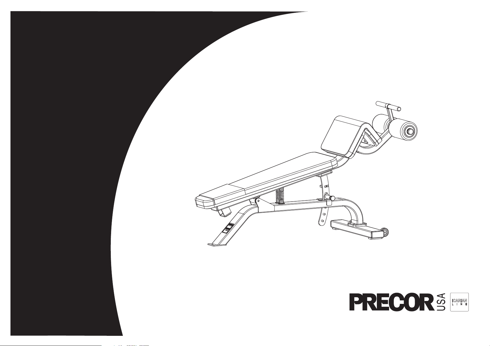
Assembly Guide
CW-113
Page 2

Page 3

CW-113 Assembly and Maintenance Guide
Important Safety Instructions
When using exercise equipment, basic precautions
should always be taken, including the following:
• Read all instructions before assembling the
CW-113. These instructions are written for your
safety and to protect the unit.
• Read each step in the assembly instructions and
follow the steps in sequence. Do not skip ahead. If
you skip ahead, you may learn later that you have
to disassemble components and that you may
have damaged the equipment which would void
the Precor Limited Warranty.
• Assemble and operate the CW-113 on a solid,
level surface. Locate the unit a few feet from walls
or furniture to provide easy access.
• Do not allow children or those unfamiliar with its
operation on or near the equipment. Do not leave
children unsupervised around the unit.
• Use the equipment only for its intended purpose.
Do not use accessory attachments that are not
recommended by the manufacturer, as such
attachments may cause injuries.
• Do not attempt to service the CW-113 yourself.
The unit does not contain any user-serviceable
parts.
Obtaining Service
For information about product operation or service,
refer to the Precor web site at www.precor.com where
you can also find customer support numbers or a list of
Precor authorized service centers.
If you call or e-mail Customer Support, have the serial
number available.
You can find the serial number printed on a label
affixed to the CW-113. For future reference, write the
serial number in the space provided below.
Serial number: _______________________
Important Safety Instructions
IMPORTANT SAFETY INSTRUCTIONS
page 3
Page 4

CW-113 Assembly and Maintenance Guide
Table of Contents
Important Safety Instructions ...................................................................................................3
Obtaining Service .................................................................................................................... 3
Preparations................................................................................................... 5
1
2
Unpacking the Equipment ....................................................................................................... 5
Required Tools......................................................................................................................... 5
Installation Requirements ........................................................................................................ 5
Hardware Kit ............................................................................................................................ 6
Assembly Instructions .................................................................................. 7
Open the Box .......................................................................................................................... 7
Assemble the Unit ................................................................................................................... 8
Assemble the Pads.................................................................................................................. 11
Clean the Pads and Assembly ................................................................................................ 12
Limited Warranty Statement .................................................................................................... 13
Specifications ............................................................................................................. Back cover
Table of Contents
page 4
Page 5

CW-113 Assembly and Maintenance Guide
1
The CW-113 parts are inspected before shipment.
Each unit contains several pieces that require
assembly. You will need to obtain adult assistance
during the assembly process.
Unpacking the Equipment
When you open the box, carefully unpack the pieces
and lay them on the floor near the location where you
plan to use them.
CAUTION: Be careful when you use a utility knife to
remove the packaging material. Do not cut the
upholstery or scratch the paint.
If any items are missing, contact the dealer from whom
you purchased the unit. For more information, refer to
Obtaining Service.
Preparations
Required Tools
Tools that you need to obtain before assembling the
unit include:
❏ Wire cutter or utility knife
❏ ¾-inch open end wrench
3
❏
⁄32-inch Allen wrench
Installation Requirements
Follow these installation requirements when
assembling the unit:
• Review the
• Assemble the unit where it will be used.
• Install components in the sequence shown.
• Insert all fasteners in the same direction. For
aesthetic purposes, insert all the fasteners in the
same direction unless specified (in text or
illustrations) to do otherwise.
• Leave room for adjustments. Tighten fasteners to
keep the unit stable, but leave room for
adjustments.
Important Safety Instructions
.
Preparations
page 5
Page 6

CW-113 Assembly and Maintenance Guide
Hardware Kit
Fastener Qty
³⁄₈ x ¾-inch Buttonhead screw (A) 12
³⁄₈-inch Split washer (B) 14
³⁄₈ x 2¾-inch Buttonhead screw (C) 2
³⁄₈-inch Washer (D) 2
Fastener Qty
½-inch Washer (F) 2
½-inch Lock nut (G) 1
⁵⁄₁₆ x 3-inch Buttonhead screw (H) 4
⁵⁄₁₆-inch Split washer (J) 10
½ x 5¼-inch Buttonhead screw (E) 1
Preparations, continued
⁵⁄₁₆-inch Washer (K) 10
⁵⁄₁₆ x 1¼-inch Buttonhead screw (L) 6
page 6
Page 7

CW-113 Assembly and Maintenance Guide
Assembly
2
Assembly of the CW-113 takes about 50 minutes to
complete. If this is the first time you have assembled
this type of equipment, plan on allowing more time.
Be careful to open boxes and assemble components in
the sequence presented in thie manual.
Instructions
Handlebar
Roller Pads
Thigh Pad
Open the Box
Use wire cutters to open the box and remove packing
materials.
The illustration shows how the CW-113 will look when
you have completed its assembly. The callouts identify
specific pieces.
Back
Support
Back Pad
Holder Assembly
Back Adjustment
Stabilizer
Main Frame
Assembly Instructions
page 7
Page 8

CW-113 Assembly and Maintenance Guide
Assemble the Unit
1. Attach the Main Frame to the Stabilizer using
four ¾-inch buttonhead screws (A)
four ³⁄₈-inch split washers (B)
Wrench tighten.
Note: Make sure the wheels on the Stabilizer are
positioned as shown in the illustration.
2. Attach two Spring Cushions to the Main Frame
using
two 2¾-inch buttonhead screws (C)
two ³⁄₈-inch split washers (B)
two ³⁄₈-inch washers (D)
Wrench tighten.
3. Insert two Springs onto the Spring Cushions.
4. Turn the Back Support over and attach the Back
Adjustment to the Back Support using
four ¾-inch buttonhead screws (A)
four ³⁄₈-inch split washers (B)
Wrench tighten.
4 - ¾" buttonhead screws
4 - split washers
Spring Cushion
2 - 2¾" buttonhead screws
2 - washers
2 - split washers
2 - Spring Cushions
4 - ¾" buttonhead screws
4 - split washers
Assemble the Unit
page 8
Page 9

CW-113 Assembly and Maintenance Guide
5. Pull on the Adjustment Pin and slide the Back
Adjustment through the Main Frame. Release the
Adjustment Pin while it is aligned with the Back
Adjustment middle hole.
Note: Make sure the Springs slide onto the posts
on the bottom of the Back Support
6. Slide the Sleeve through the Back Support. Align
the holes and attach the Back Support to the Main
Frame using
one 5¼-inch buttonhead screw (E)
two ½-inch washers (F)
one ½-inch locknut (G)
Wrench tighten using a ¾-inch open end wrench.
7. Attach the Holder Assembly to the Back Support
using
four ¾-inch buttonhead screws (A)
four ³⁄₈-inch split washers (B)
Wrench tighten.
Sleeve
1 - 5¼" buttonhead screw
1 - sleeve
2 - washers
1 - locknut
Assemble the Unit, continued
4 - ¾" buttonhead screws
4 - split washers
page 9
Page 10

CW-113 Assembly and Maintenance Guide
8. Slide the Roller Bar through Holder Assembly, and
then place a Round Cap onto each end of the
Roller Bar. Slide the Round Caps against the
Holder Assembly.
9. Slide a Roller Pad onto each end of the Roller Bar,
followed by a Roller Cap. Place an Aluminum Cap
on each end of the Roller Bar and tighten the set
screws.
10. Tighten the set screws at the end of the Holder
Assembly to secure the Roller Bar, then insert the
Square Cap into the Holder Assembly.
11. Insert a Round Cap into each end of the
Handlebar, and then slide the Handlebar through
the Holder Assembly. Slide a Grip onto each end of
the Handlebar, then secure the Handlebar to the
Holder Assembly by tightening the set screws with
a 3⁄32-inch Allen wrench.
Roller Bar
Assemble the Unit, continued
page 10
Page 11

CW-113 Assembly and Maintenance Guide
Assemble the Pads
1. Attach the Back Pad to the Back Support using
four 3-inch buttonhead screws (H)
four 5⁄16-inch split washer (J)
four 5⁄16-inch washers (K)
Wrench tighten.
2. Attach the Thigh Pad to the Back Support using
six 1¼-inch buttonhead screws (L)
six 5⁄16-inch split washers (J)
six 5⁄16-inch washers (K)
Wrench tighten.
This completes the assembly of the CW-113.
4 - 3" buttonhead screws
4 - split washers
4 - washers
Assemble the Pads
6 - 1¼" buttonhead screws
6 - split washers
6 - washers
page 11
Page 12

CW-113 Assembly and Maintenance Guide
Clean the Pads and Assembly
To clean the pads moisten a clean, soft cloth in a mild
solution of soap and water and wipe the pads
thoroughly. Dry the pads with a clean, dry cloth.
Use the same procedure to clean the Main Frame and
plastic parts.
Frequently vacuum the floor underneath the CW-113 to
prevent the accumulation of dust and dirt. If necessary,
use the Back Support to lift the front end and tip the
CW-113 onto its wheels to roll it to a different location.
Clean the Pads and Assembly
page 12
Page 13

Limited Warranty
Precor, Incorporated (PRECOR) will repair or replace any of the following components which are
defective as to materials or workmanship for products manufactured and sold after June 1, 1990:
ICARIAN & STRETCH CENTER:
Lifetime:Structural Steel Framework
Five Years: Rotary Bearings, Weight Stacks, Pulleys, Guide Rods, Structural Moving
Par ts
One Year: Cable, Linear Bearings, Springs
Ninety Days: Upholstery, Handgrips, All Other Items Not Listed
Not withstanding the above, all warranties provided by PRECOR shall terminate upon transfer of
ownership of the equipment by the original owner. PRECOR may require the Customer to affirm
that he is the original owner of the equipment before providing warranty services. This warranty
does not extend to any components which become defective due to abuse, misuse, or lack of
proper maintenance or if the equipment under warranty has been modified or altered in anyway.
The Customer seeking repair or replacement of defective equipment must notify PRECOR at the
address set forth on the back cover of such defect, admit PRECOR authorized service
representatives during normal business hours to effect repairs and pre-pay all defective equipment
within thirty (30) days of its receipt of notice of the defect from a Customer or the equipment itself.
THIS WARRANTY IS LIMITED TO REPAIR AND/OR REPLACEMENT OF DEFECTIVE
EQUIPMENT. Except to the extent it is precluded from doing so in a particular state or other
jurisdiction by applicable law. PRECOR DISCLAIMS ANY AND ALL OTHER WARRANTIES
WHETHER EXPRESSED OR IMPLIED, INCLUDING BUT NOT LIMITED TO ANY IMPLIED
WARRANTY OR MERCHANTABILITY OR FITNESS FOR A PARTICULAR PURPOSE. Moreover, if
any damage or defect is caused by the transport carrier, such claims must be filed with the carrier
at the time of delivery. PRECOR DISCLAIMS ANY AND ALL RESPONSIBILITY FOR SUCH
DAMAGE OR DEFECT, NO DEALER, EMPLOYEE, SALES REPRESENTATIVE OR AGENT HAS
ANY AUTHORITY TO MAKE ANY WARRANTIES OR REPRESENTATIONS CONCERNING
PRECOR EQUIPMENT BEYOND THOSE SET FORTH IN THIS WARRANTY AND IN OTHER
OFFICIAL PRECOR LITERATURE: AND PRECOR DISCLAIMS ALL RESPONSIBILITY FOR ANY
SUCH UNAUTHORIZED WARRANTIES OR REPRESENTATIONS.
An individual purchasing PRECOR equipment in California for personal, family or household
purposes has the right to have defective equipment serviced or repaired during the warranty period.
The warranty period will be extended for the number of whole days that the equipment is out of the
buyer’s hands for warranty repairs. If a defect exists within the warranty period, the warranty will not
expire until the defect has been fixed. The warranty period will also be extended if the warranty
repairs have not been performed due to delays caused by circumstances beyond the control of the
buyer, or if the warranty repairs did not remedy the defect and the buyer notifies PRECOR or its
authorized dealer or sales representative of the failure of the repairs within sixty (60) days after they
were completed. If after a reasonable number of attempts, the defect has not been fixed, the buyer
may return the equipment for a replacement or a refund subject, in either case, to deduction of a
reasonable charge for usage. This time extension does not affect the protections or remedies the
buyer has under other laws. Purchasers of PRECOR strength equipment have the right to bring an
action at law or in equity to resolve disputes concerning or to enforce the provisions of this warranty.
Some states do not allow the exclusion of limitations of incidental or consequential damages and/or
limitation on how long an implied warranty lasts, so the above limitations or exclusions may not
apply to all Customers. This warranty gives Customers specific legal rights; Customers may also
have other rights which may vary from state to state.
Effective 27 November 2006
P/N CW31973-102
page 13
Page 14

CW-113 Assembly and Maintenance Guide
Notes:
page 14
Page 15

Page 16

CW-113 Specifications
Length: 64 inches (163 cm)
Height: 39 inches (99 cm)
Width: 30 inches (76 cm)
Shipping weight: 131 lb (59.42 kg)
Precor Incorporated
20031 142nd Avenue NE
P.O. Box 7202
Woodinville, WA USA 98072-4002
Precor is a registered trademark of Precor Incorporated.
Specifications subject to change without notice.
Copyright 2007 Precor Incorporated.
www.precor.com
NOTICE:
Precor is widely recognized for its innovative, award winning designs of exercise equipment. Precor aggressively seeks U.S. and foreign patents for
both the mechanical construction and the visual aspects of its product design. Any party contemplating the use of Precor’s product designs is hereby
forewarned that Precor considers the unauthorized appropriation of its proprietary rights to be a very serious matter. Precor will vigorously pursue all
unauthorized appropriation of its proprietary rights.
CW-113 Assembly & Maintenance Guide CW33616-101
Warranty Statement CW31973-102
24 September 2007
 Loading...