

Page 1

Commercial Treadmill Owner’s Manual
COMMERCIAL PRODUCTS DIVISION
Page 2

COMMERCIAL PRODUCTS DIVISION
IMPORTANT SAFETY INSTRUCTIONS
When using the C956i or C954i treadmill, always follow basic precautions, including the
following:
• To ensure your safety and to protect the unit, read all the instructions before assembling and using the treadmill.
• To ensure the proper use and safety of the treadmill, make sure that all users read
this manual. Please make this manual a part of your club’s training program.
Remind the club users that before beginning any fitness program, they should
obtain complete physical examinations from their physicians.
Il est conseillé de subir un examen médical complet avant d’entre-prendre tout
programme d’exercise. Si vous avez des étourdissements ou des faiblesses, arrêtez
les exercices immédiatement.
DANGER —
WARNING —
• Do not allow children or those unfamiliar with its operation on or near the treadmill.
Do not leave children unsupervised around the treadmill.
• Never leave the treadmill unattended. Unplug the unit from the power outlet when it
is not in use, before cleaning it, and before putting on or taking off parts. Do not
adjust the running belt when someone is standing on the unit.
• Assemble and operate the treadmill on a solid, level surface. Locate the treadmill a
few feet from walls or furniture. (The minimum space requirement is one meter by two
meters directly behind the running belt.) Check the unit before each use and verify
that all fasteners are secure. Maintain the treadmill in good working condition.
• Use the treadmill only for its intended use as described in this manual. Do not use
accessory attachments that are not recommended by the manufacturer; such attachments might cause injuries.
• If you purchased the optional chest strap, review the guidelines found in the
Heart Rate Option Owner’s Manual
• Never operate the unit if it is damaged, if it is not working properly, if it has been
dropped, or if it has been dropped in water. Return the unit to a service center for
examination and repair.
• Keep all electrical components such as the motor, power cord, and I/O switch, away
from liquids to prevent shock. Do not set anything on the handrail, display console,
or hood. Place liquids, magazines and books in the appropriate receptacles.
• Keep the power cord away from heated surfaces.
• Do not operate the treadmill where aerosol (spray) products are being used or where
IMPORTANT SAFETY INSTRUCTIONS
oxygen is being administered.
• Do not use outdoors.
• The security clip must be attached at waist level prior to beginning a workout. A
cord connects the security clip to the red STOP button on the console. If a user
encounters difficulties, a strong tug on the security cord or a quick tap on the red
STOP button will stop the running belt.
To reduce the risk of electrical shock, always unplug the unit from its
power source before cleaning or performing any maintenance tasks.
To reduce the risk of burns, fire, electric shock, or injury to
persons, take the following precautions:
that is supplied with that option.
Precor
page 2
SAVE THESE INSTRUCTIONS
Page 3

COMMERCIAL PRODUCTS DIVISION
IMPORTANT SAFETY INSTRUCTIONS
• Use care when getting on or off the treadmill. Use the stationary handrail and straddle
the running belt. Step onto the running belt when the speed is at or below 1 mph
(1.5 kph).
• Never step off the treadmill while the running belt is moving. Keep your body and
head facing forward. Never attempt to turn around on the treadmill.
• Never turn ON the treadmill when someone is standing on the machine.
• Never block the air openings on the hood while operating the treadmill. Keep the air
openings clean and free of lint, hair, or anything that might impeded the free flow of
air. Never drop or insert objects into any opening.
• Wear proper exercise clothing and shoes during a workout—no loose clothing. Tie
long hair back. Keep all loose towels away from the running surface. The running
belt will not stop immediately if an object becomes caught in the belt or rollers.
• Do not rock the unit. Do not stand on the display console or hood.
• Do not overexert yourself or work to exhaustion. If you feel any pain or abnormal
symptoms, stop your workout immediately and consult your physician.
PASSWORD SECURITY
To help prevent unauthorized use, the treadmill is equipped with password protection. The
password involves entering three keys in sequence. If the correct keys are not pressed within
two minutes, further access is denied and the running belt will not move. For more information, refer to
Club Information
.
MAXIMUM USER WEIGHT
You should not allow runners over 160 kg or walkers heavier than 225 kg on the treadmill.
SAFETY APPROVAL
When identified with the ETL-c logo, the treadmill has been tested and conforms to the requirements of CAN/CSA-E-335-1/3-94, Safety of Household and Similar Electrical Appliances.
IMPORTANT SAFETY INSTRUCTIONS
SAVE THESE INSTRUCTIONS
page 3
Page 4
COMMERCIAL PRODUCTS DIVISION
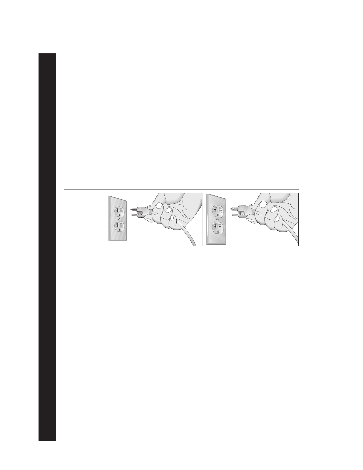
GROUNDING INSTRUCTIONS
The C956i or C954i treadmill must be grounded. If it should malfunction or break down, grounding provides a path of least resistance for electric current which reduces the risk of electrical
shock. The C956i or C954i treadmill is equipped with a power cord having an equipment-grounding conductor and a grounding plug. The plug must be inserted into an appropriate outlet that is
properly installed and grounded in accordance with all local codes and ordinances Refer to
Diagram 1. If you do not follow these
Warranty.
Grounding Instructions
, you could void the Precor Limited
DANGER —
cian or service person if you are in doubt as to whether the treadmill is properly grounded.
Do not modify the plug provided with the treadmill or use an adapter. If the plug doesn’t
fit the outlet, get a proper outlet installed by a qualified technician.
Diagram 1
Correct power
outlet for U.S.
Markets:
120-volt and
240-volt plugs.
120-volt grounding plug 240-volt grounding plug
120V Units and 240V Units Designated for U.S. Markets
The C956i or C954i treadmill must be connected to a dedicated, grounded circuit. A 20 amp
dedicated circuit is recommended.
Improper connection of the equipment-grounding conductor can
result in a risk of electric shock. Check with a qualified electri-
IMPORTANT SAFETY INSTRUCTIONS
page 4
SAVE THESE INSTRUCTIONS
Page 5

COMMERCIAL PRODUCTS DIVISION
Table of Contents
Important Safety Instructions ................................................................ 2
Password Security ................................................................................................ 3
Maximum User Weight ......................................................................................... 3
Safety Approval .................................................................................................... 3
Grounding Instructions .........................................................................................4
Radio Frequency Interference (RFI) .....................................................................7
European Applications ......................................................................................... 7
Obtaining Service ................................................................................................. 8
About this Manual ................................................................................................. 8
Unpacking the Treadmill ......................................................................... 9
Standard Equipment ............................................................................................. 9
Other Equipment .................................................................................................. 9
Hardware Kit .......................................................................................................10
Setting Up the Treadmill........................................................................ 11
Installation Requirements ................................................................................... 11
Additional tools needed ......................................................................................11
Assembly Instructions ........................................................................................11
Turning the Unit ON and OFF .............................................................................21
Checking the Alignment of the Running Belt ......................................................21
Club Information.................................................................................... 22
Treadmill Location within the Club ...................................................................... 22
Weight Limitations ..............................................................................................22
Changing the Club Settings ................................................................................22
Selecting the Language ...................................................................................... 24
Determining the Units of Measure ......................................................................24
Selecting Password Protection ...........................................................................24
Determining the Club SPEED Limit ....................................................................25
Setting a Workout Time Limit ..............................................................................25
Setting a Pause Time Limit .................................................................................25
Setting a Cool Down Time Limit ......................................................................... 25
Removing or providing a fitness test .................................................................. 26
Changing the C956i Custom Programs ..............................................................26
Viewing the Odometer, Hours of Use, Software
Version and Error Log ........................................................................................ 27
Using CSAFE Standard Equipment .................................................................... 28
page 5
Page 6

COMMERCIAL PRODUCTS DIVISION
Table of Contents
The C956i/C954i Display ....................................................................... 29
Features on the Display Console ....................................................................... 29
Top Display Windows.......................................................................................... 30
Upper Display (C956i only).................................................................................30
Center Display (C956i and C954i) ......................................................................30
Keys on the Display Console .............................................................................. 32
Keypad Tips........................................................................................................ 32
Exercising on the Treadmill .................................................................. 36
Using the Security Clip .......................................................................................36
Entering a Password .......................................................................................... 36
Pause, Cool Down, Summary and Exit Features ............................................... 36
Quick Steps to Working Out ............................................................................... 38
Workout Tips ...................................................................................................... 38
Cooling Down After a Workout ........................................................................... 40
Programs................................................................................................ 41
The Heart Rate Feature ..................................................................................... 41
Using the SmartRate Feature .............................................................................41
Manual Mode and the QUICKSTART Key ..........................................................43
C956i Track Course ............................................................................................43
Programs with Preset Inclines ............................................................................ 43
C956i Interval Program ...................................................................................... 44
C956i Custom Programs ....................................................................................45
Random Program ...............................................................................................45
C956i Heart Rate Program ................................................................................. 45
C956i Weight Loss Program ............................................................................... 46
C956i Goal-based Programs .............................................................................. 47
Fitness Test ........................................................................................................ 47
Fitness Test Guidelines ............................................................................... 47
Maintenance........................................................................................... 49
Inspection ...........................................................................................................49
Cleaning the Equipment .....................................................................................49
Aligning and Adjusting the Running Belt ............................................................ 50
Storing the Chest Strap ......................................................................................51
Servicing the Treadmill ....................................................................................... 51
Long Term Storage .............................................................................................51
Warranty Registration Card ................................................................................ 53
Precor Limited Warranty .....................................................................................55
Specifications ....................................................................................... back cover
page 6
Page 7

COMMERCIAL PRODUCTS DIVISION
RADIO FREQUENCY INTERFERENCE (RFI)
Federal Communications Commission Part 15
The treadmill has been tested and found to comply with:
• The IEC EMC Directive (international electromagnetic compatibility certification)
• The limits for a Class A digital device, pursuant to Part 15 of the FCC Rules.
These limits are designed to provide reasonable protection against harmful
interference in a commercial installation. The treadmill generates, uses, and
can radiate radio frequency energy and, if not installed and used in accordance with the owner’s manual instructions, may cause harmful interference
to radio communications. Operation of the treadmill in a residential area is
likely to cause harmful interference. If this occurs, the user will be required to
correct the interference at his or her own expense.
CAUTION —
Per FCC rules, changes or modifications to the
treadmill not expressly approved by Precor, could
void the user’s authority to operate the equipment.
Canadian Department of Communications
This digital apparatus does not exceed the Class A limits for radio noise emissions
from digital apparatus set out in the Radio Interference Regulations of the Canadian
Department of Communications.
Le présent appareil numérique n’émet pas de bruits radioéélectriques dépassant les
limites applicables aux appareils numériques de la Class A prescrites dans le
Règlement sur le brouillage radioélectrique édicté par le ministére des Communications du Canada.
EUROPEAN APPLICATIONS
This treadmill is a Class S/B certified machine according to EN957-1,6 standards.
This treadmill conforms to the requirements of the European Council Directive
89/336/EEC,
standards:
EN55022, Limits & Methods of Measurement of Radio Interference, Information
Technology Equipment. Per the standard, the treadmill is a Class A product. In a
domestic environment, this product may cause radio interference, in which case
the user is responsible to take adequate measures to alleviate the interference.
Electromagnetic Compatibility
and has been tested to the following
EN50082-1, Generic Immunity Standard for Residential, Commercial and Light
Industrial Products.
This treadmill additionally conforms to the requirements of the European Council
Directive 73/23/EEC,
standard:
IEC 335-1, Safety of Household and similar Electrical Appliances.
Low Voltage Directive
and has been tested to the following
page 7
Page 8

COMMERCIAL PRODUCTS DIVISION
OBTAINING SERVICE
Do not attempt to service the treadmill yourself except for the maintenance tasks
described in this manual. The treadmill does not contain any user-serviceable parts.
For information about product operation or service, visit the Precor Web Site at
www.precor.com or contact an authorized Precor Commercial Products Customer
Support Representative at 1-888-665-4404.
To help customer support personnel expedite your call, have your serial number
available. The serial number can be found on the shipping container or on the label
near the power receptacle. If you have any questions regarding the treadmill, use
the model and serial numbers whenever you call a Precor dealer or Commercial
Products Customer Support Representative.
Model number: C956i or C954i
Unit number: _____ Serial number: ______________________________
Unit number: _____ Serial number: ______________________________
Unit number: _____ Serial number: ______________________________
ABOUT THIS MANUAL
This manual includes instructions for installing and using the treadmill. To maximize
the use of the treadmill, please study this manual thoroughly. The manual uses the
following conventions for identifying special information:
Note: Contains additional information.
Important: Indicates information to which you should pay special attention.
CAUTION: Indicates steps or information necessary to prevent harm to your-
self or damage to the equipment.
WARNING:
equipment and injuries to yourself.
DANGER:
Provides instructions to prevent electrical damage to the
Indicates steps you must take to prevent electrical shock.
page 8
Page 9

COMMERCIAL PRODUCTS DIVISION
Unpacking the Treadmill
Thank you for purchasing the Precor C956i or C954i treadmill. Built to the exacting
standards of the health club environment, the treadmill is intended for commercial
use and can withstand the rigors of daily club use with little maintenance.
Important: Before using the treadmill, we urge you to familiarize yourself and
your staff with the entire Owner’s Manual. Understanding this manual will help
you and your customers use the treadmill safely and successfully.
CAUTION: This unit weighs over 350 pounds (158 kilograms). To prevent injury
to yourself or damage to the equipment, obtain appropriate assistance before
removing the unit from the pallet.
The treadmill is carefully inspected before shipment so it should arrive in good
operating condition. Precor ships the unit in the following pieces:
❑ Base frame assembly with hood ❑ Two handrails (left and right)
❑ Two upright supports ❑ Hardware kit
❑ Display console with cable ❑ Owner’s Manual
If any items are missing, refer to
STANDARD EQUIPMENT
The treadmill incorporates the Precor SmartRate® and Heart Rate features into its
display console. Devices, such as FitLinxx®, that are CSAFE compatible, can also
be attached.
The Precor heart rate feature is standard on the C956i and provides electrode
strips, called “grips,” on the center handrail. When a user grasps the metal
portion of the center handrail, a heart rate is transmitted to the receiver.
Note: If a user does not wish to use the touch-sensitive hand grips, an optional
chest strap can be purchased and worn. The chest strap transmits the user’s
heart rate and it appears as a number in the Heart Rate display.
Important: The Precor “touch” heart rate is not available on the C954i treadmill,
but the SmartRate and heart rate features will appear on the display if the user
wears the optional chest strap.
Password security is standard on the treadmill. Club patrons have two minutes to
enter a specific key sequence before the running belt will move. For more information, refer to
Club Information
OTHER EQUIPMENT
Obtaining Service
.
.
Optional equipment available through your dealer includes:
• Chest strap.
• Long handrails.
If you are interested in obtaining Precor option kits for your unit, check with your
dealer. For customer support, see
Obtaining Service
.
page 9
Page 10
COMMERCIAL PRODUCTS DIVISION
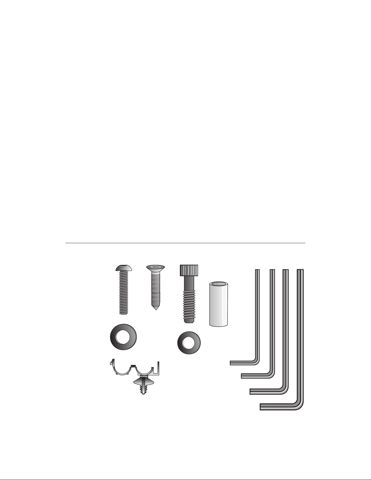
HARDWARE KIT
After unpacking the treadmill, open the hardware kit and make sure that you have
the following items shown in Diagram 2.
❑ (A) twelve 1-inch buttonhead hex screws
❑ (B) sixteen stainless steel washers — place on 1-inch screws
❑ (C) four ⁵⁄₈-inch flat head hex screws — attach to upper handrails
❑ (D) four 3¹⁄₂-inch socket head screws — install upright supports
❑ (E) four black washers — fasteners for upright supports
❑ (F) four barrel spacers — place on 3¹⁄₂-inch socket head screws after washers
❑ (G) ⁵⁄₃₂-inch hex key — attach handrails to display frame
❑ (H) ³⁄₁₆-inch hex key — attach hood, mount upright supports, attach display
and handrails to base frame
❑ (J) ¹⁄₄-inch hex key — attach upright supports to base mounting brackets
Diagram 2
❑ (K) ⁵⁄₁₆-inch hex key — adjust running belt
❑ (L) six power cord clips
Hardware kit (not shown to scale).
A
C
D
B
E
L
F
G
H
J
K
page 10
Note: After assembling the treadmill, be sure to store the hex keys in a secure
place. The tools are used for specific maintenance procedures that are described
in this manual.
Page 11

COMMERCIAL PRODUCTS DIVISION
Setting Up the Treadmill
You do not need any special knowledge or experience to set up the treadmill.
However, because of its size and weight, you will need to obtain assistance.
INSTALLATION REQUIREMENTS
Follow these installation requirements when installing the treadmill.
If you do not
install the treadmill according to the following guidelines, you could void the Precor
limited warranty.
• Set up the treadmill on a solid, flat surface. Unpack and assemble the tread-
mill close to where you plan to use it. Make sure that the flat surface under the unit
is smooth and level. A level unit is required for the user’s safety and proper operation.
• Provide ample space around the unit. It is important to keep the area
around the treadmill open and free from encumbrances. The minimum space
requirement needed for user safety and proper maintenance is one meter
by two meters square, directly behind the running belt.
• Fill out and mail the limited warranty card. The serial number can be found
on the shipping container or on the label near the power receptacle. Write the
serial number onto the Precor limited warranty card found on the back cover of
this manual and in the
• Use the appropriate voltage, dedicated circuit, and grounding as speci-
fied on the treadmill. The treadmill is available in both 120-volt and 240-volt
models. Refer to the treadmill’s identification label to determine the voltage
that your treadmill requires. Both the 120-volt and 240-volt models require a
dedicated circuit. A 20 amp circuit is recommended.
CAUTION: Do not use a non-grounded outlet or transformer. Do not
remove or otherwise bypass the plug with an adapter. Electrical damage
can occur and void the Precor limited warranty if the treadmill is
connected to an improper power source. Refer to
Obtaining Service
section.
Grounding Instructions
.
ADDITIONAL TOOLS NEEDED
Obtain the following tools
❑ Wire cutter ❑ Medium weight string
❑ Bubble level ❑ ¹⁄₂-inch box end wrench
❑ SAE standard socket set with a ratchet or 8-inch crescent wrench
before
ASSEMBLY INSTRUCTIONS
Take the following steps to assemble the treadmill.
CAUTION: To avoid injury and ensure your safety, get assistance
before moving the treadmill off the pallet. Do not drop the unit.
1. Think about the site and location. Have your assistants help place the shipping
carton close to the location where you plan to use the treadmill. Break down the
side walls of the shipping carton so that they lie flat. Remove the loose contents.
assembling the treadmill.
page 11
Page 12
COMMERCIAL PRODUCTS DIVISION
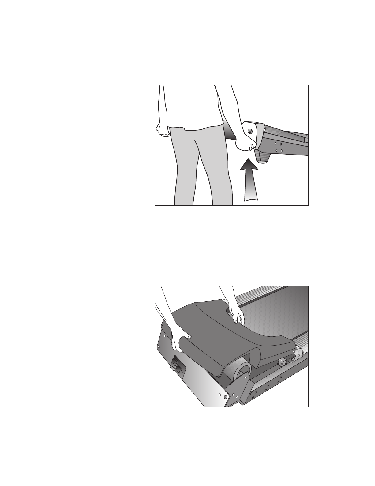
Diagram 3
Lift the rear of
the unit and roll
it to its assembly
location.
Rear end cap
Lift the unit by
grasping the
hand holds
inside the rear
end caps.
2. Make sure that the power switch is OFF. Check the ON/OFF power switch
on the front of the treadmill. Place the switch in the O (OFF) position. Make
sure that the treadmill is not plugged into a power source.
3. Move the treadmill. Diagram 3. Grasp the hand holds inside the rear end
caps and use proper lifting techniques to lift the rear end so that you can roll
the treadmill on its front wheels. To avoid injury to yourself or damage to the
unit, ask for help in maneuvering the treadmill.
Diagram 4
page 12
Remove the
hood.
Hood
4. Remove the hood. Diagram 4. Gently, lift the hood off the treadmill and set it
aside.
Page 13
COMMERCIAL PRODUCTS DIVISION
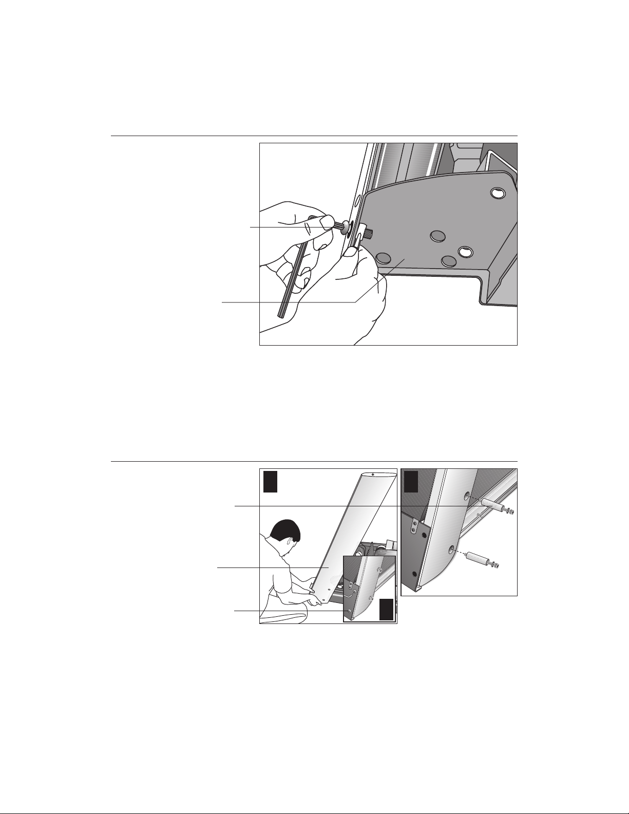
Diagram 5
Remove the
shipping
fasteners from
the left side front
panel.
Shipping
fasteners found
on left and right
sides of the front
panel.
Left side
mounting bracket
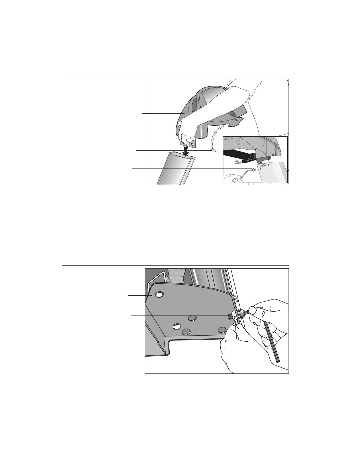
5. Attach the left side upright support. Diagram 5. Take the following steps.
a. Remove the shipping fasteners from the front panel. With the supplied
hex key and a ½-inch box end wrench, loosen and remove the two bolts
and nuts on the left side of the front panel. These fasteners hold the front
panel in place during shipping. (The front panel will drop slightly when
you remove the fasteners.) Discard the nuts, but keep the bolts.
Diagram 6
Secure the left
upright support.
Screws (D),
washers (E),
and barrel
spacers (F)
Left upright
support
Shipping
fasteners with
washers (B)
1 2
3
b. Attach the left upright support by placing it inside the base mount and align-
ing the mounting holes. Obtain two long sockethead screws (D), washers (E)
and barrel spacers (F) from the Hardware kit. Place a washer and barrel
sleeve on each screw and insert the fasteners through the side of the upright
support and into the base mounts. Use the ¼-inch hex key to secure the
screws, but leave room for adjustments. See Diagram 6, #1 and #2.
c. Remove two stainless steel washers (B) from the Hardware kit and place
a washer on each of the two shipping fasteners. Reinsert the two shipping
fasteners removed in step 5a, and finger tighten. See Diagram 6, #3.
page 13
Page 14
COMMERCIAL PRODUCTS DIVISION
Diagram 7
Attach the
display console
to the left upright
support.
Display console
Display cable
Screws (A) with
washers (B)
Left side upright
support
CAUTION: To avoid damage to the display cable, read the following steps
carefully. Damage to the cable due to improper assembly is not covered
by the Precor limited warranty.
6. Secure the display console to the left upright support. Diagram 7.
Remove any tape or wire ties that secure the display cable. Unwrap the
cable to remove kinks. Ask an assistant to hold the display console in place
while you attach it to the left upright support using two buttonhead screws
(A) with washer (B). Finger tighten.
Diagram 8
page 14
Remove right
side front panel
screws.
Right side
mounting bracket
Front panel
fasteners
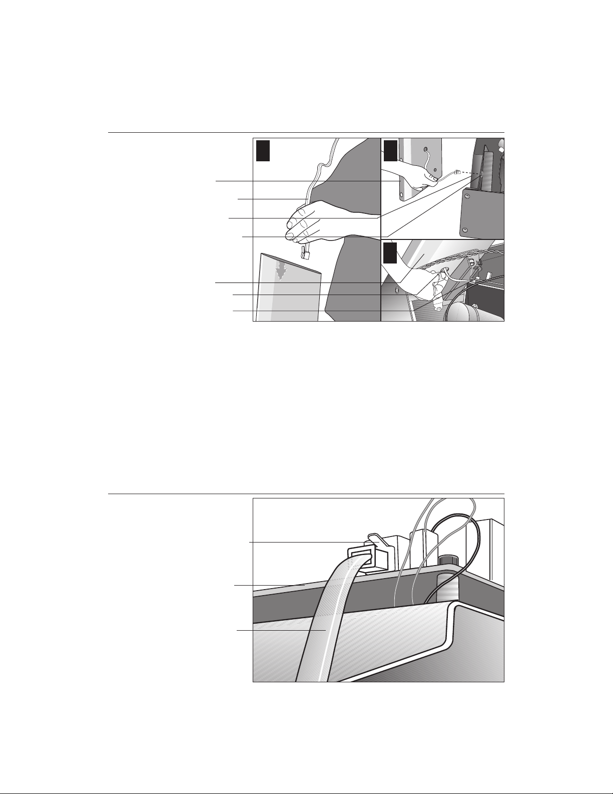
7. Prepare to attach the right side upright. Diagram 8. Take the following steps:
a. Remove the shipping fasteners from the right front panel. Follow the same
process as in step 5a. With the supplied hex key and a ¹⁄₂-inch box end wrench,
loosen and remove the two bolts and nuts on the right side of the front panel.
Page 15
COMMERCIAL PRODUCTS DIVISION
Diagram 9
Route the cable.
1
Right upright
support
Display cable
Base frame
Base mounting
bracket
Right upright
support
Bracket hole
Lower board
2
3
b. Route the display cable through the right upright support. Ask an assistant to
hold the upright support close to the right side mounting bracket. Route the
cable through the upright support (see Diagram 9, #1) and pull it out of the
large hole on the side of the support near its base. Diagram 9, #2.
Note: If you encounter difficulties with the cable, try tying a string to the
end of the cable. Attach a washer to the opposite end for weight and route
it through the upright support.
Diagram 10
c. Ask your assistant to position the right upright support inside the base mount-
ing bracket and align the mounting holes as you pull the cable through the
mounting bracket hole in the base frame. See Diagram 9, #3.
Connect the
cable.
Cable connector
Lower board
Display cable
d. Plug the cable connector into its receptacle on the lower board near the
motor. See Diagram 10. A definite “click” is heard when the cable is properly
attached. If you do not hear and feel the connector snap into place, reinsert it.
page 15
Page 16
COMMERCIAL PRODUCTS DIVISION
Diagram 11
Secure the right
upright support.
Screws (D),
washers (E),
and barrel
spacers (F)
Tighten so that
the upright is
secure, but
leave room for
adjustments.
Front panel
Shipping
fasteners with
washers (B)
2
1
3
8. Secure the right side upright support. Diagram 11. Obtain two long
sockethead screws (D), washers (E) and barrel spacers (F) from the Hardware
kit. Place a washer and barrel sleeve on each bolt and insert the fasteners
through the side of the upright support and into the base mounts. Diagram 11,
#1. Secure the upright support using the ¼-inch hex key. See Diagram 11, #2.
Important: Do not securely tighten the screws until after the unit has been fully
assembled. Make sure that the bolt and spacer do not pinch the cable.
Diagram 12
page 16
9. Remove two stainless steel washers (B) from the Hardware kit and place one on
each of the two bolts removed in step 7a. Reinsert the bolts and finger tighten.
Diagram 11, #3.
Secure the
display console.
Display console
1-
inch screws (A)
with washers (B)
Tighten the
screws, but
leave room for
adjustments.
10. Secure the display console to the upright supports. Diagram 12, #1. Align
the display console with the right side upright support mounts. Insert two 1-inch
screws (A) with washers (B) and finger tighten. Use the supplied hex key to
secure the screws on both upright supports, but leave room for adjustments.
See inset in Diagram 12, #2.
Page 17
COMMERCIAL PRODUCTS DIVISION
Diagram 13
Handrail alignment and installation.
Handrail
Lower
handrail
bracket
Screw (A)
and
washer (B)
Screw (C)
1
5
2
Console
extension
3
4
Important: With the handrails attached, the width of the treadmill is 36.75
inches (93 cm). It will not fit through a standard 32-inch doorway.
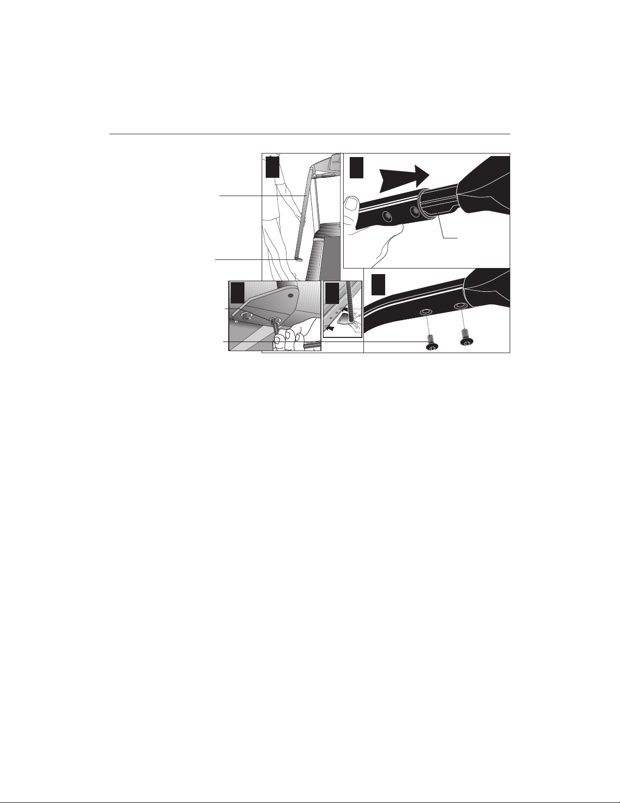
11. Attach the handrails. Diagram 13. For ease of assembly, place the side rails
or adjustable rear feet on blocks. Obtain assistance to lift the treadmill. Do
not place blocks beneath the running bed.
To attach the handrails, perform the following steps on
one side at a time
:
a. Position the handrail as shown in Diagram 13, #1 and #2 and slide it onto the
console extension. Insert two flat head screws (C) into the upper handrail
mounts and finger tighten. See Diagram 13, #3.
b. Align the lower handrail bracket with the two base mounts and insert two
screws (A) with washers (B). See Diagram 13, #4. Tighten the screws
with the hex key. See Diagram 13, #5.
c. Return to the upper handrail screws and securely tighten each one.
d. Perform steps a. through c. on the opposite side.
e. Obtain assistance and remove the blocks from beneath the base.
page 17
Page 18

COMMERCIAL PRODUCTS DIVISION
Diagram 14
Diagram 15
Replace the
hood and
secure it.
Hood
Buttonhead
screws (A) with
washers (B)
secure the hood
to the siderail.
Buttonhead
screws (A) with
washers (B)
secure the front
of the hood.
1
2
12. Replace the hood. Diagram 14. Reposition the hood on the treadmill. Remove four buttonhead screws (A) with washers (B) from the hardware kit. Two
buttonhead screws and washers are placed through the front panel and the
remaining two screws and washers are used to secure the hood to the siderail.
Tighten the screws using the appropriate hex keys.
Secure the
fasteners and
replace the
hood.
Alternately
tighten four side
upright screws.
Alternately
tighten the four
front panel
screws.
Alternately tighten
the four screws
that secure the
display console.
2
3
1
page 18
13. Tighten all mounting screws with the hex keys provided. Diagram 15.
Start at the front of the treadmill with the four screws that attach the upright
supports to the front panel. Tightening these screws first helps pull the rest of
the treadmill’s parts into alignment. Then, proceed with tightening the four
sockethead screws (D) that secure the upright supports, the four console
assembly screws (A), the handrail assembly screws (A) and (C), and the hood
screws (shown in Diagram 14).
Page 19

COMMERCIAL PRODUCTS DIVISION
Diagram 16
Adjust the level
of the treadmill.
Bubble level
Running belt
Adjustable rear
foot
14. Level the unit. Diagram 16. Check to make sure that the running deck is level
by taking the following steps:
a. Use a bubble level as shown in Diagram 16 to verify that the running deck
is level. If the treadmill is placed on a slightly, uneven surface, adjusting the
rear feet can help, but will not compensate for extremely uneven surfaces.
Important: If you need to make adjustments, adjust one rear foot at a time.
Do not use the rear foot to raise or lower the unit more than ¾-inches.
Diagram 17
Raise or
lower the
deck.
Hand holds
on rear end
caps
Adjustable
rear foot
21
b. Adjust the rear feet. Diagram 17. To raise the rear deck, situate yourself
next to the adjustable rear foot. Ask an assistant to lift the rear of the
treadmill slightly while you turn the adjustable rear foot clockwise. Turning
the rear foot counterclockwise lowers the unit.
c. Check the level of the unit after each adjustment. Make adjustments to
the rear feet so that both carry an equal amount of the treadmill’s weight
and the load placed upon it.
Important: If the load is not equally compensated, the user will feel excessive vibration or movement at the display console.
page 19
Page 20

COMMERCIAL PRODUCTS DIVISION
Diagram 18
Diagram 19
Attach the power
cord clip.
Cord clip
Front panel
Power cord
Incline lift
1
2
CAUTION: To make sure the power cord is not pinched or damaged by the
incline lift, attach the power cord to the base frame using the clips provided.
15. Attach the power cord clip. Diagram 18, #1. Remove a cord clip from the
Hardware kit. Wrap it around the power cord near its receptacle and clamp it shut.
16. Insert the clip into the base frame. Diagram 18, #2. Insert the serrated portion
of the cord clip into the hole located under the front panel on the base frame.
Install the
remaining
cord clips.
page 20
Side rail
Power cord
17. Install the remaining cord clips. Diagram 19. Wrap at least two more cord
clips around the power cord and insert the clips into the holes found in the
frame beneath the side rail. The holes are spaced a foot apart (approximately
31 cm) along the length of the side rail.
18. Plug the power cord into a dedicated, grounded circuit. Place the clips
as needed along the length of the power cord while you route it to the power
outlet.
Important: Check the length of the power cord to make sure that it cannot
get pinched or damaged by the incline lift movement.
CAUTION: The treadmill requires a dedicated, grounded circuit. A 20 amp
dedicated circuit is recommended. Make sure that no other product or
machine uses the same circuit as the treadmill. Refer to
Instructions
.
Grounding
Page 21

COMMERCIAL PRODUCTS DIVISION
TURNING THE UNIT ON AND OFF
Use the ON/OFF (I/O) power switch, located on the front panel, to turn the unit
ON and OFF.
To complete the installation of the treadmill, continue with
Checking the Alignment
of the Running Belt.
CHECKING THE ALIGNMENT OF THE RUNNING BELT
Proper belt alignment allows the belt to remain centered and ensures smooth
operation. Realigning the belt takes a few simple adjustments and is explained in
the
Maintenance
Follow these steps to check the alignment:
1. The treadmill has adjustable rear feet. Make sure that the running surface is
level. Refer to step 14, Diagram 16.
2. Turn the unit ON.
3. Stand beside the treadmill and press QUICKSTART.
section.
4. If you are prompted for a password, press INCLINE ▼, SPEED ▼, SPEED ▲.
The running belt starts automatically after a 3-second countdown appears on
the display.
5. Press the SPEED ▲ key until the display shows a speed of 3 miles per hour
(5 kph).
6. Walk around to the rear of the unit and observe the belt for a few minutes.
The belt should run centered along the running bed. If the belt drifts off
center, you will need to make adjustments.
Important: If the belt needs alignment, make the adjustments immediately
after turning the treadmill OFF. Failure to do so might cause the belt to tear
or fray, which is not covered by the Precor Limited Warranty.
7. To stop the running belt, press the red STOP button.
8. Turn the treadmill OFF.
If the belt is functioning correctly, the treadmill is ready to use. Please continue
reading
Club Information
to learn how to customize the treadmill for your club.
page 21
Page 22

COMMERCIAL PRODUCTS DIVISION
Club Information
These next few pages provide information so you can customize the treadmill.
This section covers the following information about how to:
• determine which language appears on the display
• set password security
• set maximum speed, workout, and pause times
• design custom programs
• display the odometer and other useful information
• connect to CSAFE compatible devices
TREADMILL LOCATION WITHIN THE CLUB
It is important to keep the area around the treadmill open and free from encumbrances such as other equipment. The minimum space requirement needed for
user safety and proper maintenance is one meter by two meters square, directly
behind the running belt.
WEIGHT LIMITATIONS
You should not allow runners over 160 kg or walkers heavier than 225 kg on the
treadmill.
Diagram 20
Display console keypad.
Note: The CHANGE keys are not shown in this diagram.
Refer to Diagram 21 for its location.
CHANGING THE CLUB SETTINGS
The club settings are accessed through specific key sequences that help eliminate
unauthorized access. Refer to Diagram 20 to locate the keys. Information that you
can access and features that can be customized are as follows:
• Language — Choose to display English, German, Spanish, French, Dutch,
or Portuguese.
• Units of Measure — Select between U.S. Standard and Metric displays.
• Password Protection — Lets you enable or disable the password security
function.
• Maximum Speed — Determines the maximum speed that a user can select.
Selections range between 0.5 to 12 mph (1 - 20 kph).
Numeric keypad disabled after
accessing club settings mode.
Gently, press and hold the
▼ or ▲
available selections.
key to view the
page 22
Page 23

COMMERCIAL PRODUCTS DIVISION
• Maximum Workout Time — Sets a maximum limit on workout time.
Note: Remember that the user will get up to five minutes additional cool down
time appended to a completed program. (Refer to
Limit
.) So, adjust the maximum time limit accordingly.
Setting a Cool Down Time
• Maximum Pause Time — Sets the maximum duration in which a person can
“pause” his or her workout.
• Cool Down Time — Sets the duration in which a person can “cool down”
during his or her workout.
• Fitness Test — Provides a Fitness Test for the user when “enabled.”
• Custom Programs 1 and 2 — Provides 2 programs that can be customized
for a specific user or general club purpose.
To access the club settings, the following must occur:
❑ Check to be sure that the treadmill is turned ON.
❑ Check that the Precor banner appears on the display.
❑ Press the appropriate key sequences by taking the following steps.
Important: To access club settings mode, press STOP while the Precor banner is
displayed, and without pause, begin pressing the key sequences.
1. Begin at the Precor banner.
2. Press the STOP button, and without pause, press the following numbers:
5, 6, 5, 1, 5, 6, 5
Note: Once you begin entering the sequence above, each key must be pressed
within four seconds of the other or the Precor banner reappears and you have to
begin again.
Display key functions within the Club Custom Mode
▼▲ lets you scroll through the various
selections that appear. The longer
the key is held down, the faster
the numbers scroll past.
STOP advances to the next aspect of
the program without storing the
information that appears on the
display.
CHANGE reminds you what part of
the program you’re changing.
RESET exits club settings mode and
displays the Precor banner.
ENTER saves the information being
displayed and moves to the
next aspect of the program.
Note: The touch-sensitive keys can be gently pressed and held to view several
selections. The longer the key is held down, the faster the numbers scroll past.
page 23
Page 24

COMMERCIAL PRODUCTS DIVISION
SELECTING THE LANGUAGE
On the C956i, display prompts can appear in English, German, Spanish, French,
Dutch, or Portuguese. Use the ▼▲ keys to make your choice and press ENTER
to select it.
DETERMINING THE UNITS OF MEASURE
Two different units of measure can be selected,
selection using the ▼▲ keys. Press ENTER once the correct unit is displayed.
Note: Anytime you wish to exit the Club Custom mode, press the RESET key. The
display attributes that you selected by pressing ENTER are saved and recorded in
memory.
SELECTING PASSWORD PROTECTION
As you move through the sequence of club settings, the PASSWORD prompt
appears. You can choose to enable or disable password protection. Use the arrow
keys to change the settings.
Password Settings Description
Enabled The user must enter the proper key sequence to begin
exercising. The password prompt also appears if a user
is returning from pause mode.
Disabled The user is not prompted for a password. If you select
this option, you essentially “turn off” the password
requirement. Use this option with caution.
CAUTION: Precor recommends that you leave the password protection
enabled. If you choose to change the security of the treadmill, it is your
responsibility to make sure that no unauthorized personnel or children are
allowed on or near the treadmill.
Metric
or
U.S. standard
. Make your
page 24
When the selection you want appears on the display, press one of the following
options.
Option Function
ENTER Accepts the displayed setting and lets you continue pro-
gramming the treadmill. The change will be retained in
memory even if the treadmill is turned OFF and unplugged.
RESET Keeps the current password security unchanged and
ends programming mode. The display returns to the
Precor banner.
Red Stop button Keeps the current password security unchanged and lets
you continue programming the treadmill.
Page 25

COMMERCIAL PRODUCTS DIVISION
DETERMINING THE CLUB SPEED LIMIT
You can set the maximum speed for the treadmill. This limits how fast the running belt
moves and, consequently, how many adjustments a user can make to the treadmill’s
speed. The speed is displayed in miles per hour (mph) or kilometers per hour (kph)
depending upon the units of measure (Metric or U.S. standard) that are selected.
The ▼▲ keys let you choose a speed between: 0.5 to 12.0 mph
1.0 to 20.0 kph
Press ENTER to make your selection.
Important: If you select a number that limits the miles per hour, your change will
not affect the kilometers per hour (and vice versa). The treadmill does not convert
the speed entered in miles per hour (U.S. standard) to kilometers per hour
(Metric). It stores separate numbers for the different units of measure.
CAUTION: If you change the Unit of Measure display, be sure to check the
“Set Max Speed” setting to verify that it is correct.
SETTING A WORKOUT TIME LIMIT
You can limit how long a user works out by setting a duration between 1 and 240
minutes. The treadmill also lets you choose “no limit” which allows the user to
select a program and work out indefinitely.
Note: The QUICKSTART program is automatically limited to the workout time set
during Club Custom mode.
Use the ▼▲ keys to select a workout time limit. For example, if you set the
workout time limit to 20 minutes, the treadmill allows users to specify a workout
between 1 and 20 minutes. Users cannot specify a time longer than 20 minutes.
Press ENTER to make your selection.
Note: Take into account the user will get an additional cool down period appended
to his or her workout, so adjust the maximum time limit accordingly.
SETTING A PAUSE TIME LIMIT
Setting a pause time limit is useful because the treadmill returns to the Precor
banner at a selected interval after the STOP button is pressed whether the user
planned to return or not.
Use the ▼▲ keys to set a pause time limit between 1 and 120 seconds (2 minutes).
Press ENTER to make your selection.
SETTING A COOL DOWN TIME LIMIT
Select the time frame for a user’s cool down period. Use the ▼▲ keys to set a
cool down time limit between 1 and 5 minutes (in one minute increments). Note
that a minimum cool down of three minutes is recommended to help a user’s
heart rate return to its normal, non-exercising state.
page 25
Page 26

COMMERCIAL PRODUCTS DIVISION
REMOVING OR PROVIDING A FITNESS TEST
The Fitness Test is “disabled” at the factory, so if you wish to add the option to the
user’s choice of programs, you need to “enable” the Fitness Test.
Important: On the C956i, the Fitness Test takes the place of Custom Program 2.
After displaying a cool down time limit and entering your selection, the
Fitness Test prompt appears on the display. Use the ts keys to select “enabled”
or “disabled”.
Press ENTER to confirm your selection.
CHANGING THE C956i CUSTOM PROGRAMS
Note: This aspect of the Club Custom mode does not appear in the C954i treadmill.
Two custom programs (Program 1 and Program 2) exist in the C956i treadmill.
After you modify Program 1 (or opt to bypass it), Program 2 appears on the display. The keys on the console keypad have a different function than explained in
the chart on page 23. In the custom programs, the keys function as follows:
Custom Program Keys
SPEED ▼ or ▲ moves the blinking LED from column to column.
INCLINE ▲ or ▼ affects the incline of the selected column.
ENTER accepts any changes and stores the program in memory.
STOP or RESET exits the program (leaving it unchanged) and resets the
display to the Precor banner.
If you decide to select a custom program, you have the ability to create a new, or
“draw over” an existing, program profile. The entire program appears on the
display. A blinking LED appears at the top of the far left column and indicates the
starting position. Any incline changes that you make occur only in that column.
The treadmill’s speed is determined by the user.
Begin modifying the program profile one cell at a time using any INCLINE ▲ or ▼
key. The available incline range is from 1% to 15%. To move onto the next
column, press any SPEED ▼ or ▲ key. (Refer to the chart above.)
When you have finished making changes, press ENTER to save the program
profile. The display moves to the next Custom Program (#2) or returns to the
Precor banner (depending on which Custom Program you were modifying).
Note: To exit the custom program mode without saving any of the changes, press
STOP or RESET. The custom program that existed prior to your changes is
reinstated and the display returns to the Precor banner.
page 26
Page 27

COMMERCIAL PRODUCTS DIVISION
VIEWING THE ODOMETER, HOURS OF USE, SOFTWARE
VERSION AND ERROR LOG
The treadmill stores the cumulative miles or kilometers, the number of hours that
the unit has been in use, the software version and software type (which is valuable
when calling customer support), and an error log (useful when troubleshooting).
1. Start at the Precor banner.
2. Press the STOP button and, without pause, press the following numbers:
6, 5
The field name ODOMETER appears briefly and then the odometer value (the
cumulative distance users have travelled) appears in miles or kilometers.
Press ENTER and the number of hours (HOUR METER) that the unit has been in
use appears. The treadmill notes the passing of each 10th of an hour, but the
numeric value that appears is truncated to the nearest full hour.
Press ENTER again and the unit’s three digit SOFTWARE VERSION (upper and
lower) appears on the display.
Press ENTER once again and the ERROR LOG appears. Press any ▼ or ▲ key to
view the error messages.
Note: To clear (delete) the error log, press QUICKSTART for at least four
seconds while viewing the list. Prompts appear on the display and let you know
when the error messages have been deleted (“cleared” from memory).
Important: You cannot retrieve the error log once you have deleted it.
To view the serial number, press ENTER. Write the serial number onto the
warranty registration form and in the space provided on page 8. The serial
number is helpful should you ever need to contact Customer Support.
To return to the Precor banner, press ENTER, STOP, or RESET.
page 27
Page 28

COMMERCIAL PRODUCTS DIVISION
USING CSAFE STANDARD EQUIPMENT
The C956i and C954i are fully compatible with CSAFE protocols. If the unit is
connected to a CSAFE master device, the user will be prompted to enter a user ID. Five
zeros appear on the display. The left zero blinks to indicate that it is awaiting input. The
following table provides information about the keypad functions:
User ID Entry: Program Keys
SPEED ▼ or ▲ moves the blinking LED from field to field.
INCLINE ▲ or ▼ changes the number value in the selected field.
Number keypad use the number keys to enter a user ID. The number that is
pressed appears in the display and the next field begins to
blink. When all five user ID numbers are selected, the user
must press ENTER to submit it.
ENTER submits the displayed user ID. User ID entry is bypassed
when “00000” is displayed and the user presses ENTER.
The Program prompt appears.
RESET resets the display to the Precor banner.
A message indicates when the user ID is accepted by the CSAFE master device.
Then, the program prompt is displayed. See
Quick Steps to Working Out
.
page 28
Page 29

COMMERCIAL PRODUCTS DIVISION
The C956i/C954i Display
The C956i or C954i is designed so users can work out with minimal instruction or
training. The directions on the console and the prompts on the display will guide a
user through the entire workout session. Before the treadmill is used, however, we
recommend that you familiarize yourself with it so you can instruct your customers to
use it safely and effectively. This section covers the following information:
• an overview of the features provided on the display console
• an explanation about the available programs
• instructions for utilizing the heart rate options
FEATURES ON THE DISPLAY CONSOLE
Indicator lights show you which feature is being displayed. When you are working
out, the display presents TIME, DISTANCE, SPEED, and CALORIES. You change
what features appear on the display by pressing the CHANGE keys.
Diagram 21
SmartRate bar graph
Banner and program
profile display
(LED matrix)
During program
selection, the
program # appears
here.
Numeric keys can be
used to answer prompts
and select incline and
speed levels in a
program.
C956i Display Console
(C954i not shown)
If a heart rate is
detected, it is
displayed in this
window.
Workout statistics
display (alphanumeric)
CHANGE keys let
you choose what
information to display.
Keypad (used to input or
select data and control
the workout session)
As you exercise, the display console provides motivation by presenting constant feedback about your progress. An brief explanation of each feature on the display console
appears in Diagram 21. Look on the next page for a more thorough explanation.
Note: If an error message appears, call a Precor qualified service technician or service
center. Refer to
Obtaining Service
.
page 29
Page 30

COMMERCIAL PRODUCTS DIVISION
TOP DISPLAY WINDOWS
SmartRate: You must enter your age (during the program setup prompts),
and wear a chest strap, while in a program, before the blinking segment in the bar
graph can show the zone that your heart rate is in, either: Weight Loss or Cardiovascular.
Weight Loss Zone: Maintaining your heart rate between 55% and 70% of
your maximum aerobic heart rate, helps burn enough calories that, when
continued on a regular basis for 30 minutes or more, provides the greatest
fat-burning results.
Cardiovascular Zone: Maintaining your heart rate between 70% and 85%
of your maximum aerobic heart rate, helps you, when continued on a regular
basis for 30 minutes or more, improve your overall cardiovascular/cardiorespiratory fitness level.
Important: During a program, you will need to grasp the handrail grips before
the segment begins to blink. If you prefer not to use the touch-sensitive grips
on the handrail, you will need to wear a chest strap. Note that pressing
QUICKSTART disables the SmartRate display feature.
HEART RATE: The heart rate display lets you monitor your heart rate. When a
heart beat is detected, the number appears in the small upper right display (refer
to Diagram 21). If you do not use the touch-sensitive grips on the handrails or you
are not wearing a chest strap, your heart rate will not be detected and no pulse
rate will appear on the display.
UPPER DISPLAY (C956i only)
The Precor banner and program profiles appear in the large center display (LED
matrix). Always start a workout at the Precor banner. During workouts, the program
profile appears in the center display and corresponds to the program you selected.
As you proceed through your workout, your position is indicated by a blinking cell.
CENTER DISPLAY (C956i and C954i)
Prompts appear in this display prior to your workout. You address each prompt
using the numeric or keypad keys. Once you begin a workout, lights appear in the
columns below the window indicating which information is being displayed. You
can highlight a particular feature by pressing the appropriate CHANGE key.
The following describes the information that can appear in the display.
TIME: During your workout, a time (0:00) display appears when you begin working
out. Time appears in minutes and seconds. However, should you exceed 60
minutes (during a single workout), the TIME display converts to hours and minutes.
The TIME display shows what time remains to complete the program. An
exception to this rule exists if you pressed QUICKSTART before specifying a
program duration.
page 30
Page 31

COMMERCIAL PRODUCTS DIVISION
DISTANCE: The distance that you have travelled appears (00.00) once you begin
a workout. Distance appears in 100th mile increments. Distance can appear in
miles or kilometers. If you wish to change the display, follow the instructions found
in
Club Information
.
SPEED: Displays the running belt’s speed. The ▼ and ▲ keys let you decrease
or increase the treadmill’s speed. The maximum speed can be set by the club
(see
Club Information
). The running belt speed ranges from 0.5 to 12 mph (1 to
20 kph in Metric mode). You can also use the numeric keys to designate the speed,
once the running belt is moving. Refer to
Numeric keys
and SPEED ▼▲ on pages 33
and 34.
Note: You can check the speed (when it is not the chosen display) any time
during your workout by lightly pressing either SPEED ▼ or ▲ key (for less than two
seconds). Pressing the SPEED ▼ or ▲ key for more than two seconds causes the
treadmill’s speed to change.
CALORIES: Provides the cumulative number of calories being burned by the user.
SEGMENT TIME: Indicates the amount of time, in minutes and seconds (mm:ss),
that remain in the highlighted column (or segment) before the cell at the top of the
next column begins blinking.
INCLINE: Displays the percent of incline during your workout. The INCLINE ▲ and
▼ keys affect the treadmill’s lift and let you set an incline between 0% and 15%.
The values displayed can change (in 0.5% increments). You can also use the
numeric keys to designate the incline, once the program has begun. Refer to
Numeric Keys
and INCLINE ▲▼ on page 34.
Note: You can check the incline (when it is not the chosen display) any time during
your workout by lightly pressing either INCLINE ▲ or ▼ key for less than 2 seconds.
Pressing the INCLINE ▲ or ▼ key for more than two seconds causes the treadmill’s
incline to change.
METS: Displays the metabolic units associated with your workout.
CALORIES PER MINUTE: Indicates the approximate number of calories being
burned per minute.
PACE: Displays your target speed in minutes and seconds per mile (or kilometer).
page 31
Page 32

COMMERCIAL PRODUCTS DIVISION
KEYS ON THE DISPLAY CONSOLE
The Precor treadmills have an easy-to-use keypad that is activated by the slightest
touch. Remind users that they only need to apply gentle pressure to the keypad.
Each key on the keypad provides specific functions. Numeric keys (numbered 1 - 0)
let you enter data in answer to the display prompts and change the speed or
incline during a workout. The standard keys, CHANGE, RESET, INCLINE ▲▼,
SPEED ▼▲, and ENTER, let you enter data as well as control your workout.
The following information explains the different uses of the keys from left to right.
To locate each key, look at the display console or refer to Diagram 22.
Diagram 22
Display console keypad.
QUICKSTART
setup prompts and starts moving the
running belt. SmartRate is inactive and
default values apply.
Note: The CHANGE keys are not shown in this diagram. Refer to Diagram 22 for
its location.
KEYPAD TIPS
• Select accurate entries or features such as SmartRate will not work properly.
• Answer the setup prompts by pressing the numeric keys or the ▼ or ▲ keys.
• Press ENTER to select the information being displayed.
• QUICKSTART bypasses further selections and causes the running belt to
start moving. Default values apply (see QUICKSTART on page 34). The
SmartRate display does not appear.
Numeric keys: Indicate program #,
time limit, or goal entries. During a
workout, use these keys to select a
target speed or incline.
: Bypasses the remaining
page 32
• A time-out occurs during the setup prompts if the treadmill detects no key
presses for five seconds. Prompts appear requesting that the user press the
arrow or number keys. If no key presses occur within the next two minutes,
the display returns to the Precor banner.
• Press RESET to return to the Precor banner.
• The STOP button does not appear in Diagram 22, but its function is vital as
explained in this section.
Page 33

COMMERCIAL PRODUCTS DIVISION
Numeric Keys (1 - 0): During a workout, you can use the numeric keys to change
the treadmill’s speed or incline (in whole numbers or increments). The range of speed
(0.5 - 12 mph, 1 - 20 kph) can be set by the club, so there may be limits. Check with
the club manager. Remember, if you use the numeric keys to change the speed or
incline, you need to designate which function you are changing by pressing the SPEED
▼ or ▲ key (or the INCLINE ▲ or ▼ key) within three seconds.
Note: When you use the numeric keys to change the incline, the actual incline
appears on the display as the lift moves toward the target position. If you wish to
halt the lift’s movement, press either the INCLINE ▲ or ▼ key. The lift stops moving
and the display shows the current incline level. A similar situation occurs when you
use the numeric keys to change the speed, only it’s the running belt that is being
affected.
During the setup prompts, you can also use the numeric keys to type in a
program number, workout time, “goal” entry, and age. Note that you must press
ENTER to process your selection.
CHANGE: During a workout, the CHANGE key lets you choose which feature
appears on the display.
RESET: While you are answering the setup prompts or when the running belt is
stopped, you can cancel the program, clear the display, and return to the banner
by pressing RESET.
INCLINE
▲▼▲▼
▲▼: During a workout, the INCLINE ▲▼ keys let you increase or
▲▼▲▼
decrease the running bed’s incline. The incline changes can range from 0% to 15%
in 0.5% increments. The incline in some programs (Custom, Random and Interval)
is preset, but can be overridden by the user. An exception to these rules are the
Heart Rate and Weight Loss programs.
When you press the INCLINE ▲▼ keys, the number that appears on the display
shows the target incline (not the actual incline) because the display can change
much faster than the motor driven lift.
Another feature of the INCLINE ▲▼ keys lets you review the treadmill’s incline
any time during your workout. If incline is not one of the chosen features being displayed, you can view the actual incline by lightly touching either INCLINE ▲ or ▼ key.
You can opt to change the incline, if you hold the key down for more than
TWO seconds.
Note: The numeric keys can also be used to adjust the incline. Please refer to
Numeric Keys
above.
Important: In the Heart Rate and Weight Loss programs, the INCLINE ▲▼ keys
affect the target heart rate, not the treadmill’s incline.
STOP: When the STOP button is pressed, the running belt slows to a gradual
stop. The treadmill remains in pause mode. If the lift was moving when the STOP
button was pressed, the lift stops also and remains at its current incline level.
To resume a workout, the SPEED s must be pressed. If no key press is detected
and the pause time limit elapses, the display returns to the Precor banner. A
default time limit of two minutes exists or a “pause time limit” can be set by the
club, refer to
Club Information
.
page 33
Page 34

COMMERCIAL PRODUCTS DIVISION
Important: As a safety feature, a sharp tug on the security cord that is attached
to the STOP button will cause the running belt to stop. It is a requirement that a
user attach the security clip on his or her clothing while working out. Please refer
to Using the Security Clip.
SPEED
▼▲▼▲
▼▲: The SPEED ▲ key initiates the movement of the running belt at the
▼▲▼▲
beginning of a program and lets you designate the target speed. During a workout,
the SPEED ▼▲ keys let you increase or decrease the running
belt’s speed. Speed changes can range from 0.5 to 12 mph (1 to 20 kph) in 0.1
increments. The speed in the Interval program can be programmed by the user.
The speed of the running belt can also be modified and limited by the club. Check
with the club manager or refer to
Club Information
.
Note: When you press the SPEED ▼▲ key, the number that appears on the
display shows the target speed and may differ slightly from the actual speed
because the display can change much faster than the running belt. Eventually,
the two meet at the target speed.
Another feature of the SPEED ▼▲ keys lets you review the treadmill’s speed and
pace any time during your workout. If speed and/or pace is not one of the chosen
features being displayed, you can view the speed of the running belt and your
pace by lightly touching the SPEED ▼ or ▲ key. A 2-second display lets you
review your speed and pace. You can opt to change the speed, if you hold the key
down for a few more seconds.
Note: The numeric keys can also be used to adjust the speed. Please refer to
Numeric Keys
above.
QUICKSTART: This key lets you bypass the setup prompts and start your
workout immediately using the Manual program.
Default values apply.
page 34
QUICKSTART Default Values
Prompts Default Value
Program Manual
Time The Club limit. Weight Loss program is fixed at 28 minutes.
Weight 150 lbs. (68 kg.)
Age 0 : An Age entry must occur to utilize the SmartRate display. If
QUICKSTART is pressed
after
an
Age
is entered, then the
SmartRate display will appear when you hold onto the heart
rate touch-sensitive grips on the handrail or wear the
chest strap. If no
Age
entry occurs, the SmartRate display lights
up, but no blinking sensor appears.
Note: The heart rate touch-sensitive grips on the handrail are an option available
through your Precor dealer.
Page 35

COMMERCIAL PRODUCTS DIVISION
The QUICKSTART key can be pressed any time during the setup prompts.
Default values apply after that point. See the table below:
Press QUICKSTART at the,... The following occurs:
Precor banner You bypass the setup prompts. A message
appears,
Belt Starting 3, 2, 1,...
and your work
out begins in Manual mode.
Program prompt The displayed program is accessed.
Note: If you press QUICKSTART after
selecting the Distance Goal or Calorie Goal
programs, the default values are:
Distance Goal: 3 miles (5 kilometers)
Calorie Goal: 300
Workout Time prompt The time that appears on the display
becomes the workout time limit.
Distance Goal prompt The displayed number is set as a distance goal.
This prompt only appears when the
Distance Goal program is selected. Allowable
distance entries: 0.1 to 50.0 in miles (or
kilometers).
Calorie Goal prompt The displayed number is entered as the
calories goal. This prompt only appears when
the Calorie Goal program is selected.
ENTER between 1 to 5000 calories.
Weight prompt The weight that appears on the display
becomes your designated weight that the
treadmill uses to compute statistics. Acceptable
entries: between 0 and 999.
Age prompt The age that appears on the display
becomes your designated age that the treadmill uses to compute statistics. A
correct age entry between 0 and 99 is very
important if you plan to utilize the heart rate
characteristics of the treadmill. The
QUICKSTART key acts the same as the
ENTER key at this point because you have
answered all the setup prompts.
ENTER: Workout specific prompts need to be answered and “entered” into memory.
Pressing ENTER selects the information displayed and processes it.
page 35
Page 36

COMMERCIAL PRODUCTS DIVISION
Exercising on the Treadmill
Once the C956i or C954i is set up, it is ready to use. There are no complex instructions to follow or mandatory programming steps required to operate the treadmill.
The easy-to-understand prompts let you select a program and specify how long
you want to work out. Begin working out and then, adapt the speed and incline
level to meet your fitness goals.
CAUTION: Before beginning any fitness program, have your physician give
you a complete physical examination.
USING THE SECURITY CLIP
A security clip is attached by its cord to the red STOP button that straddles the
handrail.
out.
stop. If the security switch trips while you are working out, the treadmill retains
your workout statistics and enters pause mode. To resume your workout, re
attach the security clip to your clothing, and press the SPEED ▲ key until you
reach the desired speed.
Always attach the security clip to your clothing before each work-
A tug on the cord trips the security switch and slows the running belt to a
Important: Club owners, managers, personal trainers. Remind users how
important it is to use the security clip while working out on the treadmill. Instruct
them on how to attach it to their clothing near their waistline. If any complications
occur, a strong tug on the security cord will stop the running belt.
Note: A velcro patch is located on the right side of the console by the handrail.
Use it to store the clip while the treadmill is not being used.
ENTERING A PASSWORD
If the club chooses to secure the treadmill with password protection, you will
need to enter the following key sequence at the PASSWORD prompt:
INCLINE ▼, SPEED ▼, SPEED ▲
An asterisk appears on the display with each key press. If the correct keys are not
pressed within two minutes, the Precor banner appears on the display and the
running belt does not move.
PAUSE, COOL DOWN, SUMMARY AND EXIT FEATURES
Pausing, cooling down, and exiting are integral parts of your workout and can
be accessed any time during a program. The treadmill goes through several
prerequisites before actually exiting a program. The following tables explain the
different conditions or situations that apply.
page 36
Page 37

COMMERCIAL PRODUCTS DIVISION
In a program,
you press This is what happens...,
STOP Enter pause mode. The running belt slows to a gradual stop.
Note that you may also press the SPEED ▼ key until zero
appears on the display. Once the running belt stops, TIME
stops accruing. The display features remain, so you can
review your workout statistics. The factory setting for Pause
mode is 2 minutes (120 seconds). The club has the option to
change the setting. A duration can be set between 1 and 120
minutes and limits how long a user can pause his or her workout. Refer to
Club Information
.
In Pause mode,
you press This is what happens...,
SPEED ▲ Exits pause mode. If the password security is enabled, enter
the password and resume exercising where you left off.
RESET Displays the WORKOUT SUMMARY banner. You can scan
through your workout statistics (TIME, DISTANCE, CALORIES)
by pressing the CHANGE key. Note that the TIME display shows
the accumulated workout time including warm-up and cool
down periods. To exit the summary state, press RESET again
or wait until the time limit (two minutes) elapses. The
display returns to the Precor banner.
Note: The factory setting for pause mode is two minutes (120 seconds). The club
has the option to change the setting. A duration can be set between 1 and 120
seconds and limits how long a user can pause his or her workout. Refer to
Information
.
Club
In Cool down,
you press This is what happens...,
STOP Enters Cool down - pause mode. The running belt slows to a
gradual stop. TIME stops counting. The display features remain, so you can review your workout statistics. Note that
the Pause mode has a time limit and the club has the option
to change the setting. If you enter pause mode during your
cool down, it is of limited duration.
SPEED ▲ Once you press STOP and enter the Cool down-pause mode,
the SPEED ▲ key causes the running belt to begin moving
again and returns to your cool down, so that you can resume
where you left off. TIME continues to count down.
Note: The club has the option to limit the cool down session. A duration can be
set between 1 and 5 minutes. Refer to
Club Information
.
page 37
Page 38

COMMERCIAL PRODUCTS DIVISION
At the Workout
Summary banner,
you press This is what happens,...
RESET Returns to the Precor banner. When you complete the cool down
period (or exit from a paused mode by pressing RESET), the
WORKOUT SUMMARY banner appears. Workout statistics
except TIME, DISTANCE and CALORIES reset to zero.
(Note that the TIME display shows the accumulated workout
time including warm-up and cool down periods.) You are given
two minutes to review your workout statistics before the display
automatically resets to the Precor banner. You can also press
RESET, to return to the Precor banner.
QUICK STEPS TO WORKING OUT
The steps to working out on the C956i/C954i are listed below. A short explanation
appears on the left with the more thorough description following on the right.
CAUTION: Before beginning any fitness program, obtain a complete physical
examination from your physician.
WORKOUT TIPS
• Always attach the security clip to your clothing prior to working out.
• Check that the unit is turned ON. The I/O switch is located at the front.
• Answer setup prompts using the numeric keys or by pressing the ▼ or ▲ keys.
• Press ENTER to select the information being displayed.
• QUICKSTART bypasses further selections and starts the running belt. Default
values apply (see QUICKSTART on page 34). SmartRate is not active.
• A time-out occurs during the setup prompts if the treadmill detects no key
presses for five seconds. Prompts appear requesting that the user press the
arrow or number keys. If no key presses occur within the next two minutes,
the display returns to the Precor banner.
1
Put on the chest strap.
(Available with the Precor
Heart Rate Option.)
2
Straddle belt.
1. For your heart rate to appear on the display, you need
to wear a chest strap or hold onto the touch-sensitive
grips on the handrail.
2. Straddle the running belt. Stand close enough to the
display console so that you can extend your arms to
easily touch the keys.
3
Attach security clip
to clothing.
page 38
3. Attach the security clip to your clothing near your waistline where it will not interfere with your workout.
Page 39

COMMERCIAL PRODUCTS DIVISION
4
Select a workout
option.
4. At the Precor banner, select one of the following options:
Option Steps
To start exercising • Use the QUICKSTART key.
immediately • If needed, enter the pass-
word by pressing:
INCLINE ▼, SPEED ▼,
and SPEED ▲
An asterisk appears on the
display with each key press.
To change your workout • Use the ENTER key.
session information
Important: If you press QUICKSTART, hold on to the
handrail. A 3-second countdown appears on the display
and then, the running belt starts moving.
5
Select a program.
6
Begin exercising.
Enter the program selection,
answer prompts, and enter
your weight and age.
Note: Any time during the
setup prompts, you can
press the QUICKSTART key.
Refer to QUICKSTART on
page 34.
7
Continue exercising.
8
Cool down.
5. To display the program selections, use any ▼ or ▲ key. Press
ENTER when your selection appears.
Note: The available programs appear on the label attached
to the display console. Brief program descriptions are
provided beginning on page 41.
6. Follow the prompts on the display. Once you have entered
your weight and age, press the SPEED ▲ key to begin your
workout.
Important: Hold on to the handrail with one hand. If needed,
enter the password with your other hand. Press SPEED
and step onto the running belt while the speed is at 1 mph
(1.5 kph). Once you are comfortable with the walking or running speed, you can remove your hands from the handrail.
(Pause)
To pause during your workout session before finishing the
selected program, press the STOP button. See
Down, Summary and Exit Features
for more information.
7. If you entered Pause mode, you will need to reenter the
password and use the SPEED ▲ key to resume where you
left off.
8. When you have completed a program, a cool-down period
automatically begins. Hold onto the handrail.
▲
Pause, Cool
Note: Always incorporate a cool-down period into your
workout. The club has the option to limit its duration
between 1 and 5 minutes. See
Workout
.
Cooling Down After a
page 39
Page 40

COMMERCIAL PRODUCTS DIVISION
9
End your workout.
9. After you complete the cool-down period, the running belt
comes to a complete stop and a WORKOUT SUMMARY
banner appears. Workout statistics except TIME, DISTANCE
(Review WORKOUT
SUMMARY)
and CALORIES reset to zero. (Note that the TIME display
shows the accumulated workout time including warm-up and
cool-down periods.) You are given two minutes to review
your workout statistics before the display automatically
resets to the Precor banner. You can also press RESET, to
return to the Precor banner.
10
Remove the
security clip and
step off the treadmill.
10. Detach the security clip from your clothing and carefully
step down from the treadmill.
COOLING DOWN AFTER A WORKOUT
Cooling down is an important aspect of your workout because it helps reduce
muscle stiffness and soreness by transporting excess lactic acid out of the working muscles. Cooling down for at least three minutes helps provide a smooth
transition that allows your heart rate to return to its normal (non-exercising) state.
The treadmill automatically initiates a cool-down period once you complete a
program. A prompt appears, indicating that you are in cool down.
Note: The club has the option to limit the cool-down period. It can set a duration
between 1 and 5 minutes. Refer to
Setting a Cool Down Time Limit
.
During your cool down, the workout statistics continue to appear. The TIME display
counts down so you know how much time remains. When you complete the cool
down, a WORKOUT SUMMARY banner appears.
page 40
Page 41

COMMERCIAL PRODUCTS DIVISION
Programs
The C954i provides four programs while the C956i lets you choose between 21
variable programs. This section provides information about the special features
and functions of the treadmill’s programs and how to best utilize the:
• SmartRate feature • Manual program
• Track course • Cross Country programs
• Aerobic programs • Gluteal programs
• Interval programs • Custom programs (Fitness Test)
• Random program • Heart Rate program
• Weight Loss program • Goal-based programs
Note: To choose a program, begin at the Precor banner, enter the password and
press ENTER. User-friendly prompts guide you through the program selections.
Refer to
THE HEART RATE FEATURE
To use the heart rate features you must wear the chest strap while
working out unless you are using the C956i with the touch-sensitive handrail
grips. The chest strap transmits your heart rate signal to the receiver installed in
the display console. The signal appears as a number in the heart rate display.
This lets you monitor your heart rate even when the display is presenting other
workout statistics.
Quick Steps to Working Out
.
Note: The SmartRate display does not appear if you use the QUICKSTART key
to access a program. Refer to QUICKSTART on page 34.
USING THE SMARTRATE FEATURE
Add the benefit of SmartRate to every program on the treadmill. Using SmartRate
as a visual cue helps you adjust your exercise routine to suit specific needs.
SmartRate simplifies the correlation between heart rate and exercise. You don’t
have to stop concentrating on your workout to find your pulse. It is displayed right in
front of you along with the SmartRate zone. Once you begin a workout, a blinking
segment in the bar graph appears on the left of the display, if you entered your age
during the setup prompts. The segment blinks in time with your pulse and highlights the zone that your heart rate is in: Weight Loss or Cardiovascular.
Important: Access to SmartRate is only available when the person exercising wears
a chest strap or uses the touch-sensitive grips on the handrail. (The chest strap is a
separate purchase option.)
page 41
Page 42

COMMERCIAL PRODUCTS DIVISION
Diagram 23
Target Zones.
200
190
180
170
160
150
140
130
120
110
100
90
80
70
20 25 30 35 40 45 50 55 60 65 70 75
For the ideal “weight loss” range, your heart rate should be between 55% and 70% of
your maximum aerobic heart rate. It should never exceed 85% of your maximum
aerobic heart rate or go above your target zone. Refer to Diagram 23 for your appropriate target zone.
When you maintain your heart rate between 70% and 85% of your maximum
aerobic heart rate, you are improving your overall cardiovascular/cardiorespiratory fitness level. Maintaining your heart rate in either zone (weight loss or cardiovascular) for 30 minutes or more on a regular basis (minimum three times a
week) provides the greatest benefits.
page 42
Page 43

COMMERCIAL PRODUCTS DIVISION
MANUAL MODE AND THE QUICKSTART KEY
Manual mode (C956i and C954i) lets you control the incline and running belt speed
which affects the effort you put into your workout. As with other programs, when
you complete the time limit set for the program, the automatic cool-down period
begins.
You can choose Manual mode in two different ways:
• pressing the QUICKSTART key at the Precor banner. QUICKSTART
bypasses the remaining selections and starts the Manual program. Default
values include a time limit set by the Club, a weight value of 150 lbs. (68 kg.)
and an age of zero. The SmartRate display is inactive.
• pressing ENTER at the Precor banner. This causes the C954i or C956i
to display several setup prompts. At the program prompt, you select
#1 — Manual program.
The Manual program profile appears as a flat line. Use the ▼▲ keys or the
numeric keys to adjust the incline or speed. (See pages 33 and 34 for more
information on the different key’s function.) As you proceed with your workout, a
blinking cell represents your position on the program.
C956i TRACK COURSE
The C956i Track course presents an oval as the program profile. The “lap” count
appears on the inside of the oval and a blinking segment indicates your position on
the track. One loop around the track represents 440 yards (¼ mile) or 400 meters.
You can continue (counterclockwise) around the track for the duration of the
course (which can be limited by the club). The lap count that appears represents
the number of laps completed, plus the one that your on.
PROGRAMS WITH PRESET INCLINES
In the preset programs, such as the C954i Cross Country program or the C956i
Aerobic programs, the incline is predetermined. You can make changes to the
running belt speed throughout the program and even the preset incline can be
overridden.
page 43
Page 44

COMMERCIAL PRODUCTS DIVISION
C956i INTERVAL PROGRAM
The three interval programs on the C956i let you select the rest and work
intervals according to your training regimen. In the 1-3 interval program, each
rest interval is followed by three work intervals. In the 1-2 interval program, each
rest interval is followed by two work intervals. In the 1-1 interval program, each
rest interval is followed by one work interval. You set the incline and speed for the
first rest and work interval and the software repeats the intervals throughout the
program. At any point during the workout, you can change the settings of the
current interval by simply pressing the ▼▲ or number keys. The software remembers the new settings and applies it to the appropriate rest or work interval.
Important: If you entered your age during the setup prompts and wear the chest
strap or utilize the “touch” heart rate, you can adjust the rest or work intervals to keep
your heart rate in its recommended zone. For the weight loss mode, try to maintain
your heart rate at the lower end (55% of maximum heart rate) while in the “rest”
intervals and keep it at 70% of maximum heart rate while in the “work” intervals. See
Diagram 23.
To use the interval program, take the following steps:
1. Follow the instructions in
Quick Steps to Working Out
.
2. At the program prompt, use the ▼▲ keys or numeric keys to select an
Interval program.
3. Press ENTER to proceed to the next prompt. When you finish answering the
setup prompts, the Interval program begins.
To set the incline and speed levels for each interval, take the following steps:
1. To program the rest interval, press the INCLINE and SPEED arrow keys to
change the corresponding levels. When the desired settings are displayed,
simply continue working out—you do not need to press ENTER.
The C956i returns to the “rest” settings at the beginning of each rest interval
until you readjust it or end your workout.
2. The same procedure applies to specify the settings for the work interval.
The value that appears in the SEGMENT TIME field indicates the time remaining
in the current interval. Each time the C956i changes intervals, it informs you by
displaying a message. When you complete the time limit set for the program, the
automatic cool-down period begins.
page 44
Page 45

COMMERCIAL PRODUCTS DIVISION
C956i CUSTOM PROGRAMS
Two custom programs exist on the C956i. The second custom program is available only if the Fitness Test is disabled. The club can preset the incline on these
programs. Refer to
Club Information
.
RANDOM PROGRAM
The Random program is similar to the preset incline programs. The maximum
range that the incline can be changed is fixed at plus or minus 4%. Every time a
user chooses this program, the program profile changes.
C956i HEART RATE PROGRAM
Once you set your target heart rate and the running belt’s speed, the C956i Heart
Rate program monitors your heart rate and automatically maintains it within a few
beats per minute (bpm) of the selected target. Blinking lights on the SmartRate
bar graph appear to show the “zone” that you are in.
Note: To detect a heart rate, the user must wear the chest strap or hold onto the
touch-sensitive grips on the handrail. The chest strap and touch-sensitive handrail are optional equipment that can be purchased from your dealer.
To use the Heart Rate program follow the steps found in
Out
and choose the appropriate program number at the program prompt. (Age
must
be entered during the setup prompts.) Once you have finished answering
the remaining setup prompts, the following occurs:
• The software verifies that it detects a heart rate signal. You need to press the
SPEED ▲ key to begin your workout.
Note: If your heart rate cannot be detected (transmitted through the
chest strap or touch-sensitive grips ), three dashes or the letters “HR” blink
in the heart rate display. Once a heart rate is detected the number that
corresponds to your heart rate appears.
• The treadmill provides a 3-minute warm-up period before entering the Heart
Rate program. During this time, you may make changes to the incline by
using the numeric keypad or INCLINE ▲▼ keys. Use the SPEED ▼▲ keys
to set the running belt’s speed.
Note: If your heart rate moves into the target zone for your age during the
3-minute warm-up period, the Heart Rate Program begins concurrently.
• After the warm-up period, the treadmill automatically adjusts the incline to
Quick Steps to Working
page 45
Page 46

COMMERCIAL PRODUCTS DIVISION
keep your heart rate at the selected target. Check the SmartRate display to
see if you are in your preferred zone (cardiovascular or weight loss).
Important: Once you exit the warm-up period and begin the program, the
INCLINE ▼▲ keys no longer affect the actual incline of the treadmill.
Instead the keys are used to change your target heart rate. If you change
your target heart rate, the treadmill automatically readjusts the incline so
that your heart rate remains on target.
CAUTION: A warning message will appear if you go above your
maximum recommended heart rate target zone. Heed the warning and
get permission from your personal physician before working out above
the maximum recommended zone for your age and fitness level. See
Diagram 23 for the recommended target zones.
• When you reach the time limit, a cool-down period begins. You can override
the speed and incline by pressing the ▼ or ▲ keys.
Note: The speed remains constant, if you were at or below 1 mph (1.5 kph).
C956i WEIGHT LOSS PROGRAM
The Precor Weight Loss program incorporates the latest findings on fat-burning
and weight loss through exercise. It is based on research at the world-renowned
Cooper Institute for Aerobics Research and it is designed to help you burn the most
fat during a 28-minute workout, while minimizing the risk of discomfort and injury.
The Weight Loss program is similar to the Heart Rate Program, but the target heart
rates differ. The rest interval’s target heart rate is preset to 55% of (220 - your age),
while the work interval is preset to 70% of (220 - your age). The C956i automatically
adjusts the incline of the treadmill and maintains your heart rate settings while in
the rest or work intervals.
Note: For the C956i to detect a heart rate, the user must wear the chest strap or
hold onto the touch-sensitive grips on the handrail. The chest strap is optional
equipment that can be purchased from your dealer.
To use the Weight Loss program, follow the steps found in
ing Out
program number. Refer to the program label to the side of the display.
. When the program prompt appears, enter the appropriate
Quick Steps to Work-
Important: During your workout, you can change the target heart rate using the
INCLINE
▼▲
keys. The treadmill automatically readjusts the incline so that your
heart rate remains on target.
Note: When you complete the time limit set for the program, the automatic cooldown period begins.
C956i GOAL-BASED PROGRAMS
page 46
Page 47

COMMERCIAL PRODUCTS DIVISION
These C956i programs are similar to the time-based Manual program except that the
user’s position and program duration are based on a “distance” or “calorie” goal.
Note: A club time limit may exist for these programs. Refer to
When you complete the goal set for the program, the automatic cool-down period
begins.
FITNESS TEST
The Fitness Test provides a means of comparing your fitness level with official
fitness test of the International Association of Firefighters (IAFF). The Fitness
Test is written using the Gerkin Protocol, which is the basis for the official IAFF
fitness test and part of their Wellness and Fitness Initiative.
Important: You must enter your age during the setup prompts and wear a
chest strap or grasp the touch-sensitive portion of the handrail throughout the test.
Note: The club can remove the Fitness Test from the choice of programs on the
treadmill. If Custom Program 2 appears as program number 16 on the C956i, the
Fitness Test has been disabled by the club and is no longer available to the user.
Ask the club owner or manager for assistance.
Fitness Test Guidelines
Before selecting the Fitness Test, read the following guidelines:
• you must enter your age at the AGE setup prompt.
• you must wear the chest strap or grasp the touch-sensitive portion of the
handrail throughout the test.
Club Information
.
• let the test adjust the running belt’s speed and incline for you. The keyboard
keys are disabled during the test. However, if you need to stop the running
belt to regain control or reduce your heart rate, press the red STOP button.
• when you finish the Fitness Test, the running belt’s speed slows to 3 mph
(5 kph) and the incline returns to zero. A 1-minute cool-down period is
appended to the test. After which, you can press QUICKSTART to enter the
Manual program and continue cooling down. Press the SPEED ▼▲ keys to
regulate the running belt and return your heart rate to a normal, restful state.
To use the Fitness Test follow the steps found in
Quick Steps to Working Out
and
choose the appropriate program number at the prompt. Follow the remaining
page 47
Page 48

COMMERCIAL PRODUCTS DIVISION
setup prompts to enter your AGE. Once you have finished answering the setup
prompts, the following occurs:
• The software verifies that it detects a heart rate signal. You need to press the
SPEED ▲ key to begin your workout.
Note: If your heart rate cannot be detected (transmitted through the
chest strap or touch-sensitive grips), three dashes or the letters “HR” blink
in the heart rate display. Once a heart rate is detected the number that
corresponds to your heart rate appears.
• The treadmill provides a 3-minute warm-up period before entering the
Fitness Test.
• After the warm-up period, the treadmill automatically adjusts the running belt
and treadmill incline according to the Gerkin protocol for this Fitness Test.
The Fitness Test ends if any one of the following occurs:
• you press the STOP button.
• your heart rate rises above 85% of the maximum allowable heart rate
(220 minus your age) and remains there for more than 15 seconds. Refer to
Diagram 23.
• your heart rate cannot be detected or is no longer being transmitted.
• you complete the test.
The C956i or C954i is built to withstand the rigors of the health club environment.
However, as club manager or owner, you are responsible for cleaning and main-
page 48
Page 49

COMMERCIAL PRODUCTS DIVISION
Maintenance
taining the unit’s integrity. If you fail to maintain the treadmill as described below,
it could affect or void the Precor limited warranty.
DANGER
from its power source before cleaning it or performing any maintenance tasks.
— To reduce the risk of electrical shock, always unplug the unit
INSPECTION
Perform a daily inspection of the treadmill.
1. Look and listen for slipping belts, loose fasteners, unusual noises, worn or
frayed power cords, and any other indications that the equipment may be in
need of service. Obtain service should you notice any of the above.
Important: If you determine that the treadmill is in need of service, move it away
from the main workout area and place an large “Out of Service” sign on it. While it
is awaiting service, remove the power cord so no one can use the treadmill.
2. Check for worn, frayed, or missing safety lanyards. Replace missing or worn
safety lanyards immediately. A safety lanyard with its security clip must be
fastened to the treadmill’s red STOP button. Do not allow users on a treadmill without it.
To order parts or to contact a Precor authorized service provider in your area,
refer to
Obtaining Service
.
CLEANING THE EQUIPMENT
Most of the working mechanisms are protected inside the treadmill’s hood and
solid base. However, for efficient operation, the treadmill relies on low friction. To
keep the friction low, the treadmill must be as clean as possible.
It is recommended that the running bed and belt be cleaned daily. Use a damp,
soft cloth to clean the staging platform, running bed and between the belt and
running bed surface as far as you can easily reach. This removes any dust or dirt
which might affect the smooth operation of the unit.
CAUTION: Never pour water or spray liquids on the display console, handrails, or treadmill. Allow the treadmill to dry completely before using.
Periodically, clean the treadmill’s frame, display console, handrails and running belt
with a dampened (not dripping wet),
and water. To clean the grooves on the belt, use a soft nylon scrub brush. Vacuum the
floor underneath the unit every week to prevent the accumulation of dust and dirt.
The Precor Heart Rate equipment requires little maintenance beyond keeping it
dust free. Dampen a sponge or soft cloth in mild soap and water to wipe the chest
strap. Dry the surface thoroughly with a clean towel.
clean
cloth using a diluted solution of mild soap
ALIGNING AND ADJUSTING THE RUNNING BELT
The correct alignment of the running belt is critical to the smooth operation of the
page 49
Page 50

COMMERCIAL PRODUCTS DIVISION
Diagram 24
Align the
running belt.
Side rail
Adjust the bolt
using a
hex key.
Right side rear
end cap
Running belt
⁵⁄₁₆
-inch
treadmill. The belt is properly aligned at the factory. However, during shipping and
handling or by use on an uneven surface, the belt may move off center and
require a few simple adjustments.
Before aligning the running belt, check its operation by following the procedure in
Checking the Alignment of the Running Belt
. If you determine that the belt needs
alignment, follow the instructions here.
CAUTION: Special care must be taken when aligning the running belt. Turn
OFF the treadmill while adjusting or working near the rear roller. Remove
any loose clothing and tie back your hair. Be very careful to keep your
finger or any other object clear of the belt and rollers, especially in front of
the roller and behind the deck. The treadmill will not stop immediately if an
object becomes caught in the belt or rollers.
page 50
Realigning the belt takes a few simple adjustments. If you are unsure about this
procedure, call Precor Customer Support (see
Obtaining Service
.)
Take the following steps to align the running belt on the treadmill. To ensure your
safety, make all adjustments while the treadmill is OFF.
1. Make sure the treadmill is OFF and the running belt has completely stopped.
2. Locate the right belt adjustment bolt in the rear end cap of the treadmill.
(To determine left and right, stand at the rear of the treadmill and face the
display.) See Diagram 24. The direction you turn the bolt depends on how
the belt is tracking. Make all belt adjustments on the
right rear corner bolt
using the hex key provided.
• If the belt is off center to the RIGHT, turn the adjusting bolt ¼ turn
wise
, which moves the running belt to the left.
• If the belt tracks off center to the LEFT, turn the bolt ¼ turn
wise
; this moves the belt to the right.
counterclock-
clock-
Important: Do not turn the adjusting bolt more than ¼ turn at a time. Overtightening the bolt can damage the treadmill.
3. Turn the unit ON.
Page 51

COMMERCIAL PRODUCTS DIVISION
4. Stand beside the treadmill and press QUICKSTART.
5. If you are prompted for a password, press INCLINE ▼, SPEED ▼, SPEED ▲.
The running belt starts automatically after the 3-second countdown appears on
the display.
6. Press the SPEED ▲ key until the display shows a speed of 3 mph (5 kph).
7. Walk around to the rear of the unit and observe the running belt for a few
minutes. The belt should run centered along the running bed. If the belt drifts
off center, you will need to make adjustments.
CAUTION: If you hear any chafing or the running belt appears to be
getting damaged, stop the running belt immediately by pressing the
red STOP button. Contact Precor Customer Support.
8. If the belt needs additional alignment, repeat steps 1 through 7 until the belt
is properly aligned.
9. After aligning the belt, press the
mill. Tighten any loose fasteners or other components on the equipment. If you
hear unusual noises or you feel that the treadmill is in need of repair or service,
contact Precor Customer Support. Refer to
STORING THE CHEST STRAP
Store the chest strap transmitter in a place where dust and dirt cannot accumulate on it such as, a closet or drawer. Be sure to keep the chest strap protected
from extremes in temperature. Do not store it in an area that may be exposed to
temperatures below 32° Fahrenheit.
SERVICING THE TREADMILL
Do not attempt to service the treadmill yourself except for the maintenance tasks
described in this manual. The unit does not contain any user-serviceable parts
that require lubrication. Refer to
LONG TERM STORAGE
When the treadmill is not in use for any length of time, turn it OFF. Ensure that the
power cord is unplugged from the wall outlet and is positioned so that it will not
become damaged or interfere with other equipment or people.
STOP
button and RESET. Turn OFF the tread-
Obtaining Service
Obtaining Service
.
.
page 51
Page 52

COMMERCIAL PRODUCTS DIVISION
Notes:
page 52
Page 53

Thank You and Welcome to Precor
We are confident that you will be pleased with your purchase and
that your new Precor equipment will help satisfy your customers’
fitness needs, while helping you meet your business goals.
To allow us to serve you better, please take a
few moments to complete and return your warranty registration.
YOU MAY ALSO REGISTER ONLINE AT
www.precor.com/warranty
If you have questions or need additional information,
contact your local dealer or call Precor Customer Support
at 800-347-4404.
Fold along dotted line and tape closed before mailing.
Woodinville, WA 98072-4002
PO Box 7202
20031 142nd Avenue NE
Precor Incorporated
COMM.
HERE
STAMP
PLACE
Page 54

TELL US ABOUT YOUR NEW PRECOR PRODUCTS TELL US ABOUT YOUR NEW PRECOR PRODUCTS
TELL US ABOUT YOUR NEW PRECOR PRODUCTS
TELL US ABOUT YOUR NEW PRECOR PRODUCTS TELL US ABOUT YOUR NEW PRECOR PRODUCTS
Date of Purchase:
Month
Day
Year
Product Serial Number(s):
The serial number is located on the shipping box and on the product.
Add additional sheets of paper or register online at www.precor.com/warranty
TELL US ABOUT YOUR F TELL US ABOUT YOUR F
TELL US ABOUT YOUR F
TELL US ABOUT YOUR F TELL US ABOUT YOUR F
❑ Mr.
❑ Mrs.
❑ Ms.
Name of Facility
Contact Person — First Name
ACILITYACILITY
ACILITY
ACILITYACILITY
Purchased from (Dealer name):
Please indicate the type and number of products purchased:
®
❑ #: ______ Elliptical Fitness CrossTrainer (EFX
)
❑ #: ______ Treadmill ❑ #: ______ Stair Climber
❑ #: ______ Cycle ❑ #: ______ Strength Station
❑ #: ______ StretchTrainer
TM
Last Name
Apt./Suite:Facility Address
Zip CodeCity
Area Code
Your Business Email Address
Facility Telephone Number
State
How many members do you have?
❑ Less than 100 ❑ 100 - 500 ❑ 500 - 1000 ❑ 1000 - 2000 ❑ 2001 +
What percentage of floor space do you allocate for cardio equipment?
❑ 0% to 20% ❑ 20% to 40% ❑ 40% to 60% ❑ 60% to 80% ❑ 80% to 100%
What type of equipment makes up your cardio offering (check all that apply)?
❑ Treadmills ❑ Ellipticals ❑ Cycles ❑ Stair Climbers ❑ Rowing Machines ❑ Other _____________
What other brands of cardio equipment do you currently offer (check all that apply):
❑ Life Fitness ❑ Tr u e ❑ Cybex ❑ StarTrac ❑ Other ______________________________
What other Precor equipment do you currently offer (check all that apply):
❑ EFX
®
❑ Cycle ❑ StretchTrainer
TM
❑ Treadmill ❑ Stair Climber ❑ Strength Machine ❑ Other ______________________________
TELL US ABOUT YOUR PURCHASE TELL US ABOUT YOUR PURCHASE
TELL US ABOUT YOUR PURCHASE
TELL US ABOUT YOUR PURCHASE TELL US ABOUT YOUR PURCHASE
Which best describes this purchase (check all that apply):
❑ First Precor product ❑ Replaces a Precor product of the same type
❑ Replaces same type of product – different brand ❑ Enhancement to equipment already owned
Please detach and mail in the warranty registration within ten days of purchase.
How did you FIRST become aware of this product (choose only one):
❑ Authorized Precor dealer ❑ Precor sales representative ❑ Trade show/conference
❑ Internet ❑ News report or product review ❑ Club/fitness magazine advertisement
❑ Trade/consumer magazine article ❑ Other ________________________________________________________
What factors MOST influenced your decision to purchase this product (choose up to three):
❑ Precor reputation ❑ Prior product experience ❑ Design/appearance ❑ Value for the price
❑ Special product features ❑ Warranty ❑ Service ❑ Rebate or sale price
P/N 45622-101 Effective 30 June 2002
Page 55

Commercial Equipment Limited Warranty
PLEASE READ THESE WARRANTY TERMS AND CONDITIONS CAREFULLY BEFORE USING YOUR PRECOR INCORPORATED PRODUCT.
BY USING THE EQUIPMENT, YOU ARE CONSENTING TO BE BOUND BY THE FOLLOWING WARRANTY TERMS AND CONDITIONS.
Limited Warranty.
Precor Incorporated warrants all new Precor products to be free from defects in materials and
manufacture for the warranty periods set forth below. The warranty periods commence on the invoice
date of the original purchase. This warranty applies only against defects discovered within the
warranty period and extends only to the original purchaser of the product. Parts repaired or replaced
under the terms of this warranty will be warranted for the remainder of the original warranty period
only. To claim under this warranty, the buyer must notify Precor or your authorized Precor dealer
within 30 days after the date of discovery of any nonconformity and make the affected product
available for inspection by Precor or its service representative. Precor’s obligations under this
warranty are limited as set forth below.
Warranty Periods and Coverage.
Commercial Cardiovascular Products, also known as C-Series Products,
(excluding StretchTrainer, Strength Products).
• Seven years frame, five years touch sensor display housing, two years parts, one year labor.
• For treadmills, five years motor fan, three years drive motor.
• For self-powered ellipticals and bikes, one year battery.
• For InSite, one year parts and labor.
• Labor coverage for options as defined below.
StretchTrainer
Five years frame, two years parts, 90 days upholstery, no labor.
Strength Products (S3.45 and S3.25 only)
Ten years frame; three years bearings, guide rods, cams, pulleys; one year belts, cables, hand
grips, miscellaneous parts; 90 days upholstery; no labor.
Options / Accessories / Battery-powered or Self-Operated Devices
Many options or accessories have components that are connected internally or mounted inside the
electronic console. The following guidelines determine the warranty for these components. If the
internal components are installed by the factory or by an authorized dealer as part of the original sale
and delivery, they have a warranty that is identical to the warranty of the equipment in which they are
connected or mounted. If the internal components are not installed by the factory or by an authorized
dealer as part of the original sale and delivery, they have a 90 days parts and labor limited warranty.
All components that are not internally connected have a 90 days parts only limited warranty.
Satisfactory proof of purchase is required in all cases.
Conditions and Restrictions.
This warranty is valid only in accordance with the conditions set forth below:
1. The warranty applies to the Precor product only while
a. it remains in the possession of the original purchaser and proof of purchase
is demonstrated,
b. it has not been subjected to accident, misuse, abuse, improper service, or non-Precor
modification.
c. claims are made within the warranty period.
2. Certain products are warranted for standard commercial use only (defined as use in non-fee
paying clubs or facilities and less than 6 hours daily use. Unapproved use voids the warranty.
Current standard commercial products include C936i, C932i, EFX524i, EFX534i.).
3. This warranty does not cover damage or equipment failure caused by electrical wiring not in
compliance with electrical codes or Precor owner’s manual specifications, or failure to provide
reasonable and necessary maintenance as outlined in the owner’s manual.
4. Except in Canada, Precor does not pay labor outside the United States.
5. Warranties outside the United States and Canada may vary. Please contact your local Dealer
for details.
This Limited Warranty shall not apply to:
1. Software (PROM) version upgrades.
2. Normal wear and tear, consumables and cosmetic items, including, but not limited to
the following: grips, seats, and labels.
3. Repairs performed on Precor equipment missing a serial number or with a serial tag
that has been altered or defaced.
4. Service calls to correct installation of the equipment or instruct owners on how to use
the equipment.
5. Pickup and delivery involved with repairs.
6. Any labor costs incurred beyond the applicable labor warranty period.
Complete this portion and keep for your records.
Purchased From: ____________________________ Example: Dealer or store name.
Phone Number: _____________________________ Example: Dealer or store telephone number.
Product/model: _____________________________ Example: EFX534i or C966i
Serial number: ______________________________
The serial number is found on the shipping container.
Disclaimer and Release.
The warranties provided herein are the exclusive
warranties given by Precor and supersede any
prior, contrary or additional representations,
whether oral or written. ANY IMPLIED WARRANTIES,
INCLUDING THE WARRANTY OF MERCHANTABILITY
OR FITNESS FOR A PARTICULAR PURPOSE THAT
APPLY TO ANY PARTS DESCRIBED ABOVE ARE
LIMITED IN DURATION TO THE PERIODS OF
EXPRESS WARRANTIES GIVEN ABOVE FOR THOSE
SAME PARTS. PRECOR HEREBY DISCLAIMS AND
EXCLUDES THOSE WARRANTIES THEREAFTER.
Some States do not allow limitations on how long
an implied warranty lasts, so the above limitation
may not apply to you. PRECOR ALSO HEREBY
DISCLAIMS AND EXCLUDES ALL OTHER OBLIGATIONS OR LIABILITIES, EXPRESS OR IMPLIED,
ARISING BY LAW OR OTHERWISE, WITH RESPECT
TO ANY NONCONFORMANCE OR DEFECT IN ANY
PRODUCT, INCLUDING BUT NOT LIMITED TO:
(A) ANY OBLIGATION, LIABILITY, RIGHT, CLAIM OR
REMEDY IN TORT, WHETHER OR NOT ARISING
FROM THE NEGLIGENCE OF PRECOR OR ITS
SUPPLIERS (WHETHER ACTIVE, PASSIVE OR
IMPUTED); AND (B) ANY OBLIGATION, LIABILITY,
RIGHT, CLAIM OR REMEDY FOR LOSS OF OR
DAMAGE TO ANY EQUIPMENT.
This disclaimer and
release shall apply even if the express warranty set
forth above fails of its essential purpose.
Exclusive Remedies.
For any product described above that fails to
conform to its warranty, Precor will provide, at
their option, one of the following: (1) repair;
(2) replacement; or (3) refund of the purchase
price. Precor Limited Warranty service may be
obtained by contacting the authorized dealer
from whom you purchased the item. Precor
compensates Servicers for warranty trips within
their normal service area to repair commercial
equipment at the customer’s location. You may
be charged a trip charge outside the service
area. THESE SHALL BE THE SOLE AND
EXCLUSIVE REMEDIES OF THE BUYER FOR
ANY BREACH OF WARRANTY.
EXCLUSION OF CONSEQUENTIAL
AND INCIDENTAL DAMAGES.
PRECOR AND/OR ITS SUPPLIERS SHALL HAVE NO
OBLIGATION OR LIABILITY, WHETHER ARISING IN
CONTRACT (INCLUDING WARRANTY), TORT
(INCLUDING ACTIVE, PASSIVE, OR IMPUTED
NEGLIGENCE AND STRICT LIABILITY), OR
OTHERWISE, FOR DAMAGE TO THE EQUIPMENT,
PROPERTY DAMAGE, LOSS OF USE, REVENUE OR
PROFIT, COST OF CAPITAL, COST OF SUBSTITUTE
EQUIPMENT, ADDITIONAL COSTS INCURRED BY
BUYER (BY WAY OF CORRECTION OR OTHERWISE)
OR ANY OTHER INCIDENTAL, SPECIAL, INDIRECT,
OR CONSEQUENTIAL DAMAGES, WHETHER
RESULTING FROM NONDELIVERY OR FROM THE
USE, MISUSE OR INABILITY TO USE THE PRODUCT.
This exclusion applies even if the above warranty
fails of its essential purposes and regardless of
whether such damages are sought for breach of
warranty, breach of contract, negligence, or strict
liability in tort or under any other legal theory. Some
states do not allow the exclusion or limitation of
incidental or consequential damages, so the above
limitation may not apply to you.
This warranty gives you specific legal rights, and
you may also have other rights, which vary from
state to state.
Effective 01 December, 2004
P/N 36286-111
Page 56

C956i and C954i Commercial Treadmills featuring Heart Rate and SmartRate® Systems
Product Specifications
Length: 86 inches (218 cm)
Width: 37 inches (93 cm) w/handrails
Height: 55 inches (140 cm)
Weight: 365 lbs (166 kg)
Shipping weight: 460 lbs (209 kg)
Running surface: 60 inches by 20 inches
(153 cm by 51 cm)
Motor: 3.2 hp continuous duty
Power: 120/240 VAC 50/60Hz
SPEED: 0.5 to 12 mph (1 to 20 kph)
INCLINE: 0 to 15% grade
Frame: Powder-coated steel
Regulatory Approvals: FCC, ETL, CE
C954i Features:
CSAFE
Heart Rate Telemetry
QuickStart
Reversible Deck
SmartRate
Password Protection
Touch-Sensitive Display
C956i Features:
CSAFE
Heart Rate Telemetry
QuickStart
Reversible Deck
SmartRate
Password Protection
Touch Heart Rate
Touch-Sensitive Display
TM
®
TM
®
Electronic Specifications
C954i Program: 4 C954i Display Readouts:
Manual Calories
Random Calories Per Minute
Cross Country Distance
Fitness Test Heart Rate*
INCLINE
Mets
Pace
SmartRate
SPEED
Time
C956i Programs: 21 C956i Display Readouts:
2 Custom (Fitness Test) Calories
2 Goal Calories Per Minute
Heart Rate* Distance
3 Interval Heart Rate*
Manual INCLINE
9 Pre-programmed Mets
Random Pace
Track Profile
Weight Loss Segment Time
SmartRate*
SPEED
Time
* The user must hold the touch-sensitive grips on the handrail or
wear a chest strap. The chest strap is an option available
through your dealer.
*
Precor Incorporated
20031 142nd Avenue NE
P.O. Box 7202
Woodinville, WA USA 98072-4002
Precor, CrossRamp, EFX, M, Move Beyond, and SmartRate
are registered trademarks of Precor incorporated.
CrossTrainer, QuickStart, and StretchTrainer are trademarks
of Precor Incorporated.
Copyright 2004 Precor Incorporated.
Specifications subject to change without notice.
www.precor.com
NOTICE:
Precor is widely recognized for its innovative, award winning designs of exercise equipment. Precor
aggressively seeks U.S. and foreign patents for both the mechanical construction and the visual
aspects of its product design. Any party contemplating the use of Precor’s product designs is hereby
forewarned that Precor considers the unauthorized appropriation of its proprietary rights to be a very
serious matter. Precor will vigorously pursue all unauthorized appropriation of its proprietary rights.
C956i/C954i Lit Kit# 47039-102
Registration Card # 45622-101
C956i/C954i Exploded Views 47421-102
OM # 47030-102
Online OM # 47030-402
Warranty Card # 36286-111
16 December 2004
 Loading...