

Page 1

Commercial T readmill Owner’ s Manual
C954
C956
COMMERCIAL PRODUCTS DIVISION
Page 2

COMMERCIAL PRODUCTS DIVISION
Before Y ou Begin
Thank you for purchasing the Precor C956 or C954 Commercial Treadmill.
Built to the exacting standards of the health club environment, the treadmill is
intended for commercial use and can withstand the rigors of daily club use with
little maintenance.
Before using Precor equipment, we urge you to familiarize yourself and staff with
the entire Owner’s Manual. Understanding this manual will help you and your
customers use the treadmill safely and successfully.
ABOUT THIS MANUAL
Inside this manual, you will find instructions for assembling and using the treadmill. To maximize the use of the unit, please study this manual thoroughly. The
manual uses the following conventions for identifying special information:
“Note:” Contains additional information that applies to the preceding text.
“Important:” Indicates information to which you should pay special attention.
“CAUTION: ” Indicates steps or information necessary to prevent harm to yourself or
damage to the equipment.
“WARNING: ” Provides instructions to prev ent electrical damage to the equipment
and prevent injuries to yourself.
“DANGER:” Indicates steps y ou m ust take to pre v ent electrical shock.
OBT AINING SERVICE
Do not attempt to service the treadmill yourself except for the maintenance tasks
described in this manual. The treadmill does not contain any user-serviceable parts.
For information about product operation or ser vice, visit the Precor Web Site at
www.precor.com or contact an authorized Precor dealer or a Precor Factory
Authorized Service Company. To locate the dealer or service person nearest you,
call 1-888-665-4404.
The serial number on the treadmill is printed on a label located on the base frame.
T o locate the serial number , verify that the treadmill is turned OFF. Then, stand at
the rear of the treadmill and face the display console, kneel down and look under
the treadmill on the inboard-side of the running bed at the left, rear corner. For
future reference, write the serial and model number and the date of purchase in
the space provided below .
Model/unit #: _____ Serial #: __________________ Date purchased:_____
Model/unit #: _____ Serial #:__________________ Date purchased: ____
Model/unit #: _____ Serial #:__________________ Date purchased: ____
page 2
Model/unit #: _____ Serial #:__________________ Date purchased: ____
If you have questions regarding the treadmill, use the model and serial number whenever you contact Precor Customer Service, your Precor dealer, or service person.
Page 3

COMMERCIAL PRODUCTS DIVISION
IMPORIMPOR
IMPOR
IMPORIMPOR
When using an electrical appliance, basic precautions should always be taken,
including the following:
• Read all instructions before using the treadmill. These instructions are written
to ensure your safety and to protect the unit.
• To ensure the proper use and safety of the treadmill, make sure that all users
read this manual. Please make this manual a part of your training program.
Before beginning any fitness program, users of this equipment should obtain a
complete physical examination from a qualified physician.
Il est conseillé de subir un examen médical complet avant d’entreprendre tout
programme d’exercise. Si vous avez des étourdissements ou des faiblesses, arrêtez
les exercices immédiatement.
DANGER
WARNING
TT
ANT SAFETY INSTRUCTIONSANT SAFETY INSTRUCTIONS
T
ANT SAFETY INSTRUCTIONS
TT
ANT SAFETY INSTRUCTIONSANT SAFETY INSTRUCTIONS
To reduce the risk of electrical shock, always unplug the
unit from its power source before cleaning or performing
any maintenance tasks.
To reduce the risk of burns, fire, electric shock, or injury to
persons, take the following precautions:
• When it is plugged in, do not leave the treadmill unattended. Unplug the treadmill
from the outlet when it is not in use, and before putting on or taking off parts.
• Do not allow children on or near the treadmill.
• Use the treadmill only for its intended use as described in this manual. Do not
use accessory attachments that are not recommended by the manufacturer—
such attachments might cause injuries.
• Never operate the unit if it has a damaged cord or plug, if it is not working
properly, if it has been dropped or damaged, or dropped in water. Return the
treadmill to a service center for examination and repair.
• Keep the power cord away from heated surfaces. Keep hands away from moving parts.
• Never block the air openings on the hood while operating the treadmill. Keep
the air openings clean and free of lint, hair, or anything that might impede the
free flow of air. Never drop or insert objects into any opening.
• Do not operate where aerosol (spray) products are being used or where o xygen
is being administered.
• Do not use outdoors.
• Turn the power switch to the OFF (O) position, when the treadmill is not in use
for an extended period of time. Then, remove the power plug from the outlet.
IMPORT ANT SAFETY INSTRUCTIONS
WARNING
Connect the treadmill to a properly grounded outlet only. See
Grounding Instructions
on page 4.
SA VE THESE INSTR UCTIONS
page 3
Page 4
COMMERCIAL PRODUCTS DIVISION
GROUNDING INSTRUCTIONS
The C956 or C954 treadmill must be grounded. If it should malfunction or
break down, grounding provides a path of least resistance for electric current
which reduces the risk of electrical shock. The C956 or C954 treadmill is
equipped with a power cord having an equipment-grounding conductor and a
grounding plug. The plug must be inser ted into an appropriate outlet that is
properly installed and grounded in accordance with all local codes and ordinances. If you do not follow these
Precor limited warranty.
Grounding Instructions
, you could void the
DANGER
Improper connection of the equipment-grounding conductor can result in a risk
of electric shock. Check with a qualified electrician or service person if you
are in doubt as to whether the treadmill is properly grounded. Do not modify
the plug provided with the treadmill—if it doesn’t fit the outlet, get a proper
outlet installed by a qualified technician.
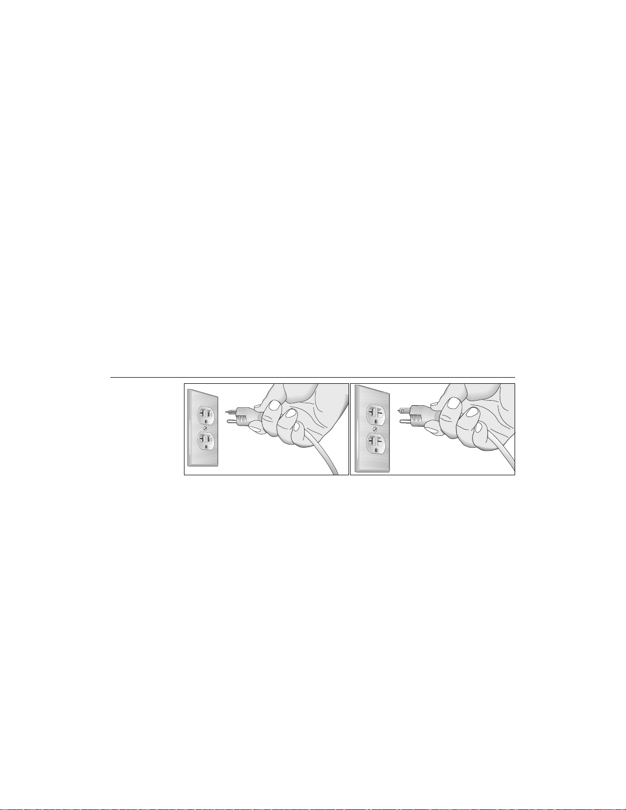
Diagram A
Correct power
outlet for U.S.
Markets: 20 amp
120-volt and
240-volt plugs.
120V Units Designated for U.S. Markets
The C956 or C954 treadmill must be connected to a 20 amp dedicated circuit
having a nominal rating of 120-volts. The treadmill’s grounding plug looks like
the plug illustrated in Diagram A. The power outlet must have the same configuration as the plug. No adapter should be used with this product.
240V Units Designated for U.S. Markets
The C956 or C954 treadmill must be connected to a 20 amp dedicated circuit
having a nominal rating of 240-volts. The treadmill is factory-equipped with a
specific power supply cord to permit connection to a proper electric circuit.
Make sure that the treadmill is connected to an outlet having the same configurations as the plug. See Diagram A. No adapter should be used with this product.
If the treadmill must be reconnected for use on a different type of electrical
circuit, the reconnection must be made by qualified service personnel.
120-volt grounding plug 240-volt grounding plug
SAFETY APPROVAL
When identified with the ETL-c logo, the treadmill has been tested and conforms to the requirements of CAN/CSA-E-335-1/2-94, Safety of Household
and Similar Electrical Appliances.
page 4
Page 5

COMMERCIAL PRODUCTS DIVISION
RFI — RADIO FREQUENCY INTERFERENCE
Federal Communications Commission Part 15
The treadmill has been tested and found to comply with,
• the IEC EMC Directive (international electromagnetic compatibility certification)
• the limits f or a Class A digital device, pursuant to Part 15 of the FCC Rules.
These limits are designed to provide reasonable protection against harmful
interference in a commercial installation. The treadmill generates , uses, and
can radiate radio frequency energy and, if not installed and used in accordance with the owner’s man ual instructions, may cause harmful interference
to radio communications. Operation of the treadmill in a residential area is
likely to cause harmful interference. If this occurs, the user will be required to
correct the interference at his or her own expense.
Per FCC rules, changes or modifications to the
CA UTION
treadmill not expressly approved by Precor, could
void the user’s authority to operate the equipment.
Canadian Department of Communications
This digital apparatus does not exceed the Class A limits for radio noise emissions from digital apparatus set out in the Radio Interference Regulations of
the Canadian Department of Communications.
Le présent appareil numérique n’émet pas de bruits radioéélectriques dépassant
les limites applicables aux appareils numériques de la Class A prescrites dans le
Règlement sur le brouillage radioélectrique édicté par le ministére des Communications du Canada.
EUROPEAN APPLICATIONS
This product conforms to the requirements of the European Council Directive 89/336/
EEC, Electromagnetic Compatibility and has been tested to the following standards:
EN55022, Limits & Methods of Measurement of Radio Interference, Information Technology Equipment (Class A).
EN50082-1, Generic Immunity Standard for Residential, Commercial and Light
Industrial Products (Class A).
This product additionally conforms to the requirements of the European Council Directive
73/23/EEC, Low V oltage Directive and has been tested to the f ollowing standard:
IEC 335-1, Safety of Household and similar Electrical Appliances.
European Applications
This product has been tested to the requirements of EN55022, “Limits & Methods of
Measurement of Radio Interference, Information Technology Equipment.” Per that
standard, the C956 or C954 treadmills are a Class A product. In a domestic environment, these products may cause radio interference, in which case the user is responsible to take adequate measures to alleviate the interference.
− −
− 240 Volt Units Only
− −
page 5
Page 6

COMMERCIAL PRODUCTS DIVISION
PERSONAL SAFETY
When using the treadmill, take the following precautions:
• Do not allow children on or near the treadmill. Do not leave children unsupervised around the treadmill.
• Assemble and operate the treadmill on a solid, surface. Locate the treadmill
a few feet from walls or furniture. Keep the area behind the treadmill clear.
• Turn OFF (O) and unplug the treadmill when adjusting or working near the rear
roller. Do not adjust the running belt when someone is standing on the unit.
• Keep all electrical components, such as the motor, power cord, and I/O switch,
away from liquids to pre v ent shock. Do not set anything on the handrail, display
console, or hood. Place liquids only in the appropriate receptacles.
• The security clip should be attached at waist level prior to beginning a
workout. A cord connects the security clip to the red STOP button on the
console. If a user encounters difficulties, the running belt can be stopped by
pulling on the cord. To resume operation, press the Speed ▲ key.
• Maintain the treadmill in good working condition. (Refer to the
Maintenance
section). Run through a check list prior to each use. Make sure that all
fasteners are secure and the belt is cleaned and running smoothly.
• Wear proper e x ercise clothing and shoes during a work out—no loose clothing. Tie long hair back. Keep all loose towels away from the running surface. The running belt will not stop immediately if an object becomes
caught in the belt or rollers.
• Use care when getting on or off the treadmill. Use the handrail(s) whenever
possible. Step onto the running belt when the speed is at 1 mph (1.6 kph).
Never step off the treadmill while the running belt is moving.
• Before the running belt begins moving (prior to a workout), and after it
stops (at the end of a workout), straddle the belt by placing your feet
firmly on the right and left side platforms.
• Never turn ON the treadmill when someone is standing on the machine.
• Keep your body and head facing f orw ard. Never attempt to turn around on
the treadmill when the running belt is moving.
• Do not rock the unit. Do not stand on the handrails, display console, or hood.
• Do not attempt to service the treadmill yourself other than the assembly and
maintenance instructions found in this manual. Refer to
Obtaining Service
.
• Do not overe x ert yourself or work to exhaustion. If you feel any pain or abnormal symptoms, stop your workout immediately and consult your physician.
PRECOR HEART RATE OPTIONS—SAFETY GUIDELINES
The Precor Heart Rate Options are created and designed exclusively for Precor
products. The equipment is very sensitive—you should use the hear t rate options
with this in mind and take time to read the guidelines found in this owner’s manual.
If you purchased the POLAR® chest strap, review the guidelines found in the
Precor Heart Rate Option Owner’s Manual
page 6
that is supplied with that option.
Page 7

COMMERCIAL PRODUCTS DIVISION
Table of Contents
Before Y ou Begin ..............................................................2
About this Manual .................................................................. 2
Obtaining Service................................................................... 2
Important Safety Instructions................................................. 3
Grounding Instructions ........................................................... 4
Safety Approval ..................................................................... 4
RFI — Radio Frequency Interf erence ..................................... 5
European Applications ........................................................... 5
Personal Saf ety...................................................................... 6
Precor Heart Rate Option - Safety Guidelines ........................ 6
Unpacking the T readmill ..................................................9
Standard Equipment............................................................... 9
Optional Equipment................................................................ 9
Hardware Kit .......................................................................... 1 0
Acquire the Appropriate Tools ................................................. 1 0
Setting Up the Treadmill ................................................11
Installation Requirements ...................................................... 11
Assembly Instructions .......................................................... 11
Turning the Unit ON and OFF ................................................ 18
Checking the Alignment of the Running Belt......................... 19
Club Information ............................................................20
Changing the Club Settings................................................... 20
Selecting the Language ......................................................... 20
Determining the Units of Measure ........................................ 21
Determining the Club Speed Limit .......................................... 2 2
Setting a Workout Time Limit ................................................ 22
Setting a Pause Time Limit.................................................... 22
Changing the C956 Custom Courses.................................... 23
Viewing the Odometer, Hours of Use,
Software Version, and Error Log ........................................... 24
Using CSAFE Standard Equipment ........................................ 24
page 7
Page 8

COMMERCIAL PRODUCTS DIVISION
Table of Contents
The C956/C954 Display..................................................2 5
Features on the Display Console............................................ 2 5
Top Display Windows ............................................................ 25
Center Display Window (C956 only) ..................................... 26
Elongated Center Display (C956 and C954) ............................ 26
Keys on the Display Console ................................................ 28
Keypad Tips........................................................................... 28
Exercising on the Treadmill...........................................32
Using the Security Clip ......................................................... 32
Pause, Cool Do wn, Summary and Exit Features .................... 3 2
Quick Steps to Working Out.................................................. 34
Workout Tips ......................................................................... 34
Cooling Down After a Workout .............................................. 35
Courses ...........................................................................36
The Heart Rate Features....................................................... 36
Utilizing the Smart Rate® Feature.......................................... 36
Manual Mode and the Quick Start Key ................................. 37
The Track Course .................................................................. 38
Preprogrammed Courses ...................................................... 38
Interval Course ..................................................................... 38
Custom Courses ................................................................... 39
Random Course .................................................................... 39
Heart Rate Course ................................................................ 40
Weight Loss Course.............................................................. 41
Goal-based Courses ............................................................. 41
Maintenance .................................................................... 42
Cleaning the Equipment ........................................................ 42
Aligning the Running Belt ...................................................... 42
Storing the POLAR® Chest Strap .......................................... 43
Servicing the Treadmill .......................................................... 43
Long T erm Storage ................................................................ 4 3
Specifications ............................................................ back cover
page 8
Page 9

COMMERCIAL PRODUCTS DIVISION
Unpacking the Treadmill
The treadmill is carefully tested and inspected before shipment so it should arrive
in good operating condition. Precor ships the unit in the following pieces:
• base frame assembly
• hood
• front assembly (includes 2 upright supports and display console)
• handrails (one for each side)
• owner’ s manual and hardware kit
CAUTION: The treadmill weighs o ver 350 pounds (157 kilograms). T o avoid
injury and ensure the safety of the unit and yourself, we suggest that you
get assistance before removing the unit from the box.
If any items are missing, contact your Precor Commercial Products Service
Representative at 1-888-665-4404.
STANDARD EQUIPMENT
Both the C956 and C954 treadmills incorporate the Precor Smart Rate® and
Heart Rate features into it’s display consoles. Devices, such as FittLinxx that
are CSAFE compatible, can also be attached.
Note: An optional POLAR® chest strap must be worn to transmit a user’s heart
rate to the display console’s receiver. Another option, Precor “touch” heart rate
can be purchased (at point of sale) and provides electrode strips on the center
handrail. When a user places his or her hands over the strips and grasps the
handrail, a heart rate is transmitted to the receiver.
OPTIONAL EQUIPMENT
Optional equipment that you can purchase through your dealer includes:
• POLAR® chest strap
• Touch Heart Rate (separate display console)
• Long handrails
If you are interested in obtaining Precor option kits for your unit, check with
you dealer. To locate the dealer nearest you, call 1-888-665-4404. For customer service, see
Obtaining Service
on page 2.
page 9
Page 10
COMMERCIAL PRODUCTS DIVISION
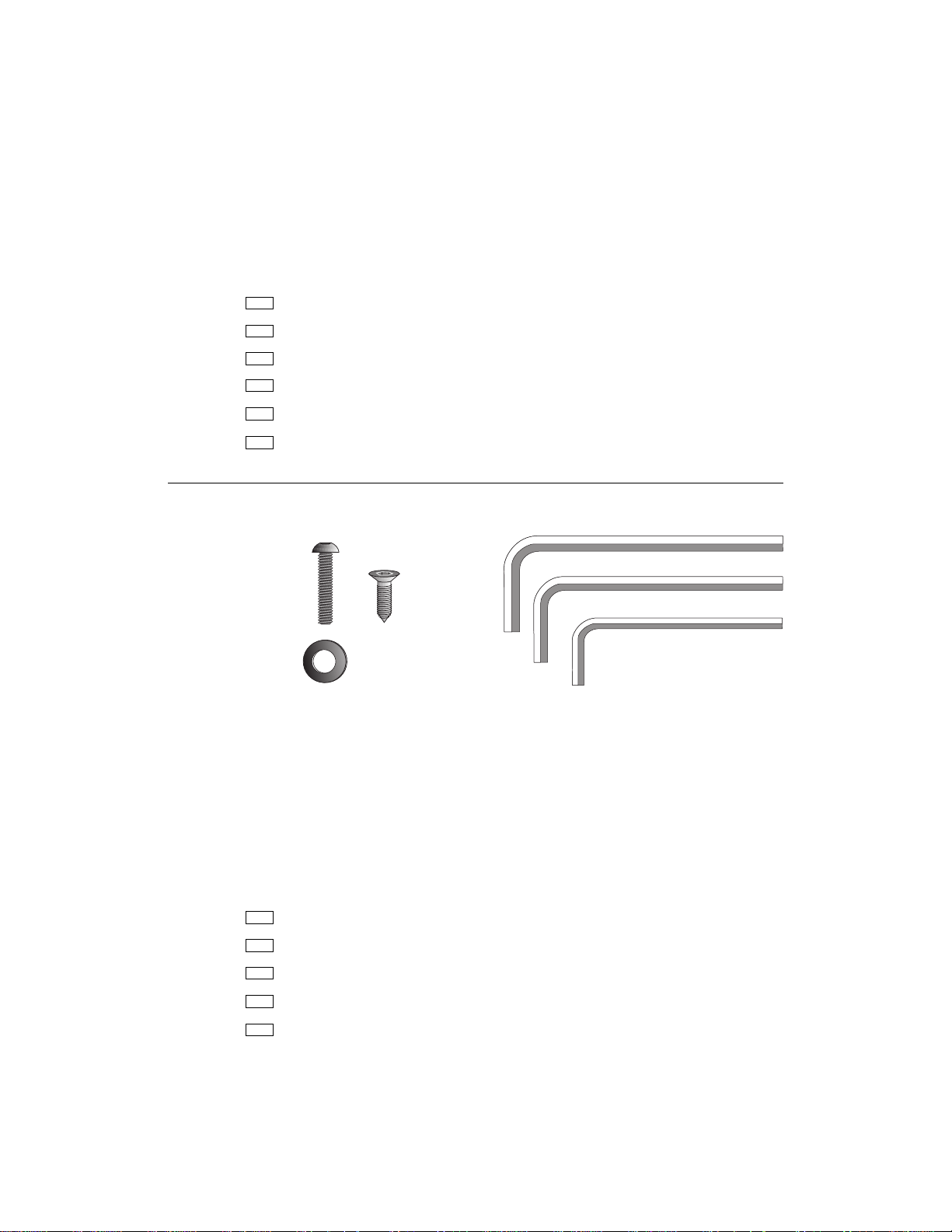
HARDWARE KIT
After unpacking the treadmill, open the hardware kit and make sure that you
have the following items shown in Diagram 1.
(A) 20 — 1” long buttonhead screws
(B) 14 — washers
(C) 4 — 1/2” long flat head screws
(D) 1/4” hex key — belt adjustment
(E) 3/16” hex key — mount uprights, display and handrails to base frame
(F) 5/32” hex key — install handrails to display and hood to base
Diagram 1
C956/C954 Hardware Kit
A
C
B
D
Note: After assembling the treadmill, be sure to store the hex keys in a secure
place. The tools are used for specific maintenance procedures that are described in
this manual.
ACQUIRE THE APPROPRIATE TOOLS
Obtain the following tools
Wire cutter
Bubble level
before
assembling the treadmill.
E
F
page 10
Medium weight string [about 1 foot (30 cm)]
Strong adhesive tape
SAE Standard socket set with a ratchet or 8” Crescent wrench
Page 11

COMMERCIAL PRODUCTS DIVISION
Setting Up the Treadmill
You do not need any special knowledge or experience to set up the treadmill.
However, you will need assistance. Because of the size and weight of the
treadmill, it is recommended that at least three adult persons assemble it.
INSTALLATION REQUIREMENTS
Follow these installation requirements when installing the treadmill.
If you do
not install the treadmill according to the following guidelines, you could void
the Precor limited warranty.
• Set up the treadmill on a solid, flat surface. Unpack and assemble the
treadmill close to where you plan to use it. Make sure that the flat surface
under the unit is smooth and level. A level unit is required for the user’s
safety and proper operation.
• Provide ample space around the unit. Open space around the unit makes
for a safer mount and dismount.
• Fill out and mail the limited warranty card. Be sure that the treadmill is
turned OFF. To locate the serial number, place yourself at the rear of the
treadmill facing the display console , kneel down and look under the treadmill on the inboard-side of the running bed of the left, rear corner. W rite
the serial number onto the Precor limited warranty card found on the bac k
cover of this manual. Refer to
number(s) there as well.
• Use the appr opriate voltage, dedicated circuit, and grounding as speci-
fied on the treadmill. The treadmill is available in both 120-volt and 240volt models. Refer to the treadmill’s identification label to determine the
voltage that your treadmill requires. Both the 120-volt and 240-volt models require a dedicated 20 amp circuit.
CAUTION: Do not use a non-grounded outlet or transformer. Do not
remove or otherwise bypass the plug with an adapter . Electrical damage can occur and void the Precor limited warranty if the treadmill is
connected to an improper power source.
Obtaining Service
on page 2 and write the
ASSEMBLY INSTRUCTIONS
Take the following steps to assemble the treadmill. We recommend
three people help with assembling the unit.
Note: The C956 and C954 treadmills have the same assembly instructions.
The differences appear in the display console and course programs.
1. Obtain assistance. Ask for assistance to help assemble the treadmill.
Have the assistant(s) help place the shipping carton close to the location
where you plan to use the treadmill. Breakdown the side walls of the
shipping carton so that they lie flat. Remove the loose contents.
at least
page 11
Page 12
COMMERCIAL PRODUCTS DIVISION
CAUTION: T o avoid injury and ensure y our safety , get assistance before
lifting the treadmill off the pallet and rolling it onto the floor. Do not
drop the unit.
2. Remove the treadmill from its shipping pallet. Eight fasteners secure the
treadmill to its pallet. Use a socket and crescent wrench to loosen and remove
the 4 lag bolts that hold the treadmill to the pallet and the 4 screws (2 on each
side) that thread through the bracket and into the unit. Discard the fasteners. Once
the fasteners have been removed, obtain several assistants to lift the treadmill off
the shipping pallet.
3. Make sure that the power is OFF. Check the ON/OFF power switch on
the front of the base assembly. Place the switch in the O (OFF) position.
Make sure that the treadmill is not plugged into a power source.
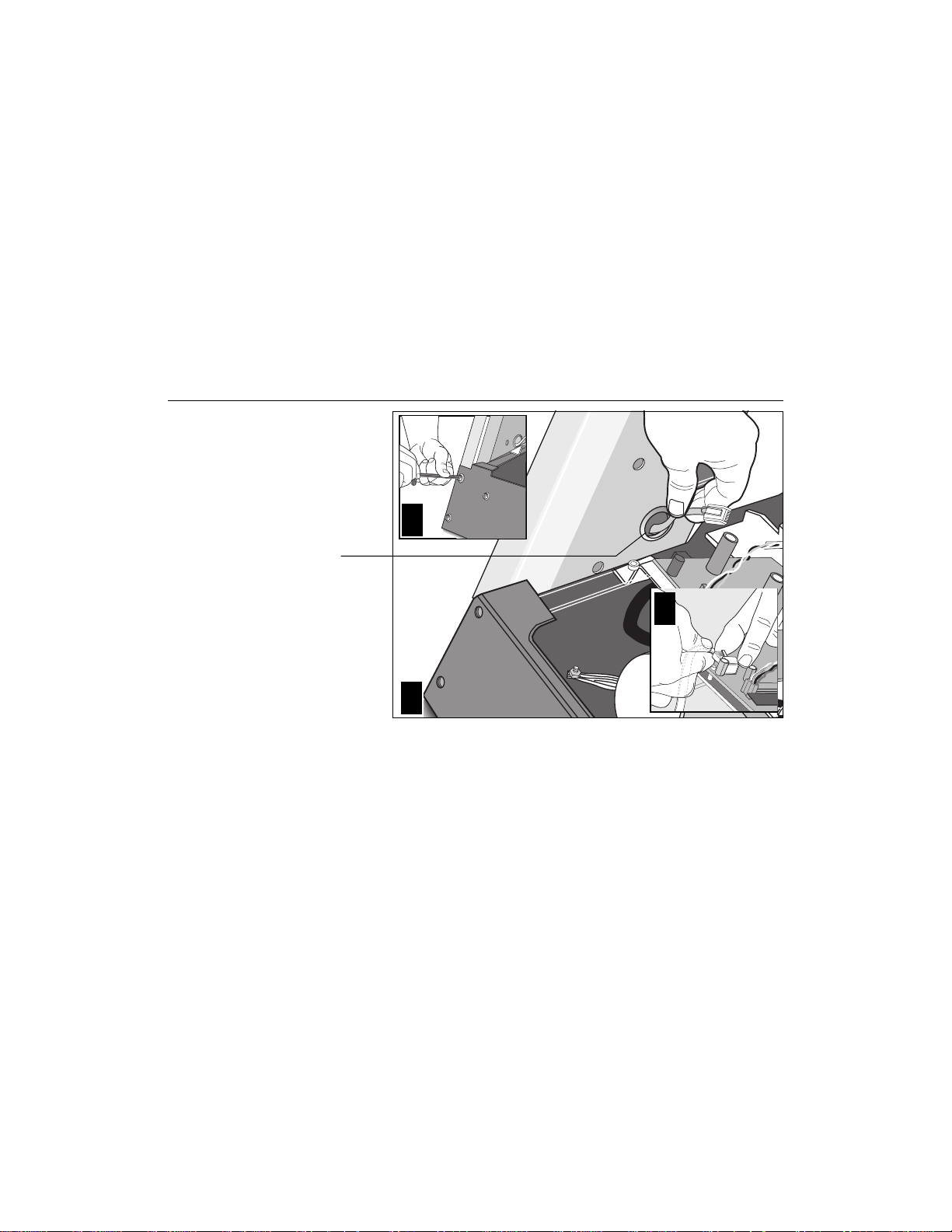
4. Loosen the screws that attach the hood to the base. With the supplied hex
key, loosen the 2 screws on the front panel and the 2 screws on the side (1 on
each side). T o detach the hood from the base , stand at the side of the treadmill.
Lift the hood up slightly and slide it toward the rear of the unit. Refer to Diagram
10.
Diagram 2
Attach the left
upright support to
the base.
Upright support
(left side)
Column support
Base assembly
5. Remove 10 buttonhead screws (A) and washers (B) from the Hardware
kit. Place the washers on the screws and split the screws into two sets of 5.
Put the sets in easy reach of the column support mounts (5 screws per side).
6. Attach the
Locate the
left side
left
upright support to the base assembly. Diagram 2.
upright support. This is the one you want to install first.
Place the upright support into the base assembly and align all 5 mounting
holes (3 on the side, 2 in the front). Insert 5 screws (A) and washers (B).
Thread the screws into the unit, but leave them loose for final adjustments.
Do not securely tighten the screws until after the display console and handrails have been installed.
page 12
Note: The left or right side of the treadmill can be determined when you
stand near the rear roller and face the motor.
Page 13
COMMERCIAL PRODUCTS DIVISION
Diagram 3
Route the cable through the upright support.
1
2
Route the cable through the
hole and tape it to the side of
the upright support .
7. Route the display cable. Diagram 3. Have an assistant hold the other sup-
port upright. See “Note:” below. Position the display console above the up-
right support and route the cable through it. Pull the cable through the hole in
the upright support. Lay the display console and upright support on the floor.
Note: Tying one end of a string to the end of the cable and the other end to
a washer may help in routing the cable. You can drop the washer through
the upright support and pull the cable through. Refer to Diagram 3, #2.
Diagram 4
Attach the display
console.
Upright support
Cable
Right side
support
Display console
(bottom side)
8. Secure the display console to the upright support. Attach the console to
the right side support before placing the assembly onto the treadmill. T o do
this, take the following steps:
page 13
Page 14
COMMERCIAL PRODUCTS DIVISION
a. Make sure that the cable is routed through the hole in the upright support.
b. Place a protective base (cardboard or plastic sheeting from the shipping
container) on the floor. Position the display console (display-side down)
onto it.
c . Remove 2 screws (A) and washers (B) from the hardware kit.
d. Align the upright support mounts with the display console’s . Insert 2 screws
and washers. Tighten the screws securely with the hex key provided.
Diagram 5
Connect the
cable and attach
the right side
support to the
base.
2
Route cable
through hole.
3
1
9. Attach the display console assembly to the base. Diagram 5. Take the
following steps to install the display console assembly onto the treadmill.
a. Position the display console and r ight upr ight suppor t over the column
support mount located on the base.
Important: Do not crimp or pinch the cable! Crimped or pinched cables
are not covered by the Precor limited warranty.
page 14
b . Carefully lower the upright support and align the mounting holes. See Dia-
gram 5 #2. Check that the display console is seated properly on the left
upright support. Insert 5 screws (A) with washers (B). Thread the screws
into the unit, but leave them loose for final adjustments. Do not securely
tighten the screws until after the display console and handrails have been
installed.
c. Plug the connector into its receptacle on the lower board. A definite “click”
is heard when the cable is properly attached. See Diagram 5 #3. If you do
not hear and feel the connector “snap” into place , reinsert it.
Page 15
COMMERCIAL PRODUCTS DIVISION
Diagram 6
Attach the
console to the
left upright
support.
Buttonhead
screws
10. Secure the display console to the left upright support. Diagram 6. Align
the mounting holes on the console to those on the left upright support.
Insert 2 screws (A) and washers (B). Do not securely tighten the screws
until after the handrails have been attached.
Important: With the handrails attached, the width of the treadmill is 36.75”
(93 cm). It will not fit through a standard 36” doorway.
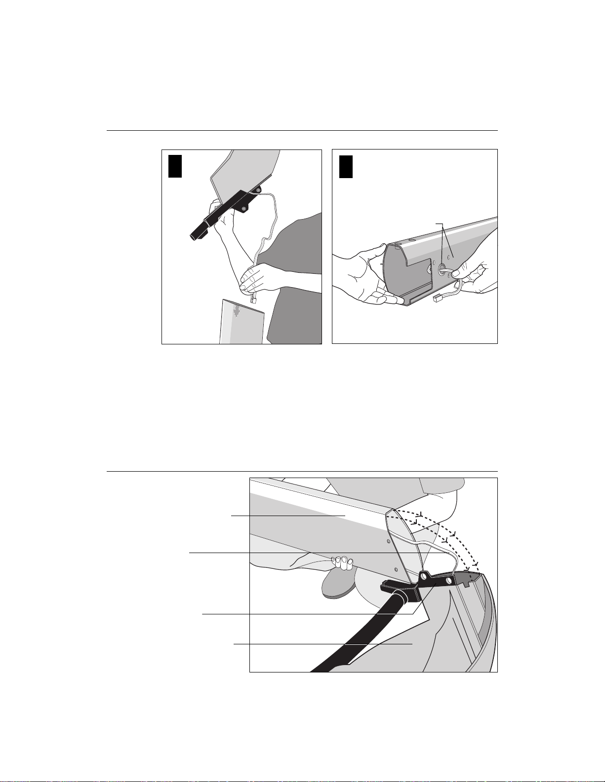
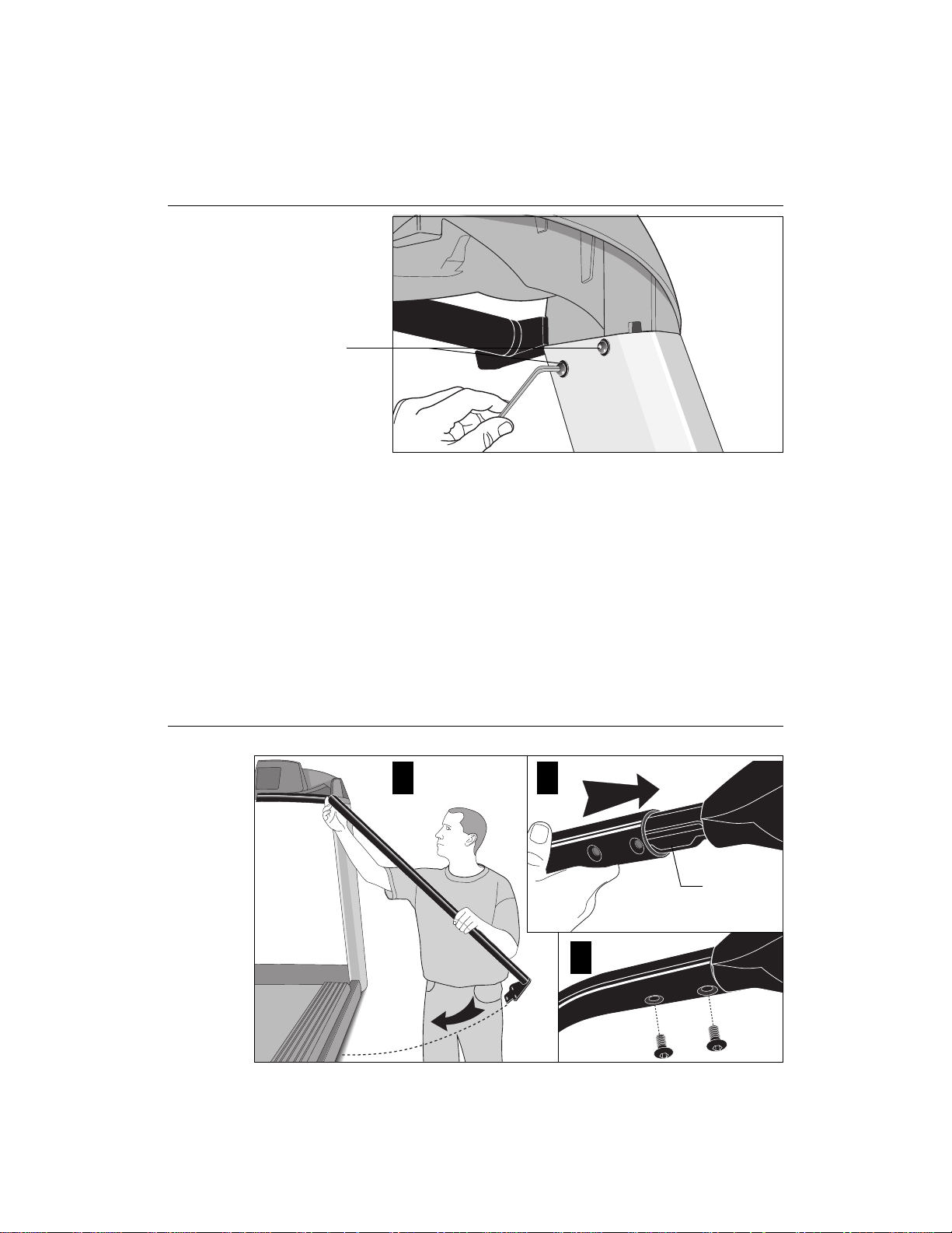
11. Attach the handrails. Diagrams 7 and 8. For ease of assembly, place the
side rails or rear feet on blocks. Obtain assistance to lift the treadmill. Do
not place blocks beneath the running bed.
Diagram 7
To attach the handrails, perform the following steps on
one side at a time
Handrail alignment and installation.
1
2
Console
extension
3
a. Alignment pins on the top of the handrails necessitate sliding the hand-
rails into the console assembly at an approximate 45ο angle. Position the
handrail as shown in Diagram 7 and slide it onto the console extension.
When the alignment pins are fully engaged, carefully lower the handrail
toward the base. Inser t 2 screws (C) and finger-tighten.
:
page 15
Page 16

COMMERCIAL PRODUCTS DIVISION
Diagram 8
Secure the handrail to the base.
Handrail bracket
b . Align the handrail bracket with the 3 base mounts and insert 3 screws (A).
See Diagram 8. Tighten the screws securely.
c. Return to the upper handrail screws and securely tighten each one.
d. Perform steps a. through c. on the opposite side.
e. Obtain assistance and remove the blocks from beneath the base.
Diagram 9
page 16
Tighten front plate
screws first. Then
securely tighten all
fasteners.
Tighten these screws
first on both sides of
the front plate.
12. Tighten all mounting screws w ith t he hex keys provided. Diagram 9.
Start at the front of the treadmill with the 4 screws that attach the upright
supports to the front plate. Tightening these screws first helps pull the rest of
the treadmill’s parts into alignment. Then, proceed with securely tightening
the upright supports and console assembly screws.
Page 17

COMMERCIAL PRODUCTS DIVISION
Diagram 10
Slide the
hood under
the 2 screws
found on the
inboard side
of both
upright
supports.
Secure the hood.
1 3
2 4
13. Attach the hood. Diagram 10. Place the hood over the motor and slide it
under
th e upper 4 screws (see Diagram 10 #1) and
found on each side) of both upr ight supports.
As you lower the hood, slide the hood under the washers and onto the screws
(2 in the front, 1 on either side of the treadmill). See Diagram 10, #2 and #3.
Retighten the screws that you loosened in step 4.
sandwiched between the base assembly and the washer s. The washer s
must be on the outside of the hood.
Tighten the screws securely using the
hex key provided.
CAUTION: Do not overtighten the screws or you may inadvertently cause
stress cracks in the plastic hood.
over
the 2 lower screws (1
Be sure that the hood is
Diagram 11
Level the unit.
1
2
14. The C956 and C954 units have adjustable rear feet. Check to make sure that the
running surface is level (use a bubble level as shown in Diagram 11). If the treadmill is placed on a slightly , uneven surf ace, adjusting the rear feet can help , but will
not compensate for extremely uneven surfaces.
page 17
Page 18

COMMERCIAL PRODUCTS DIVISION
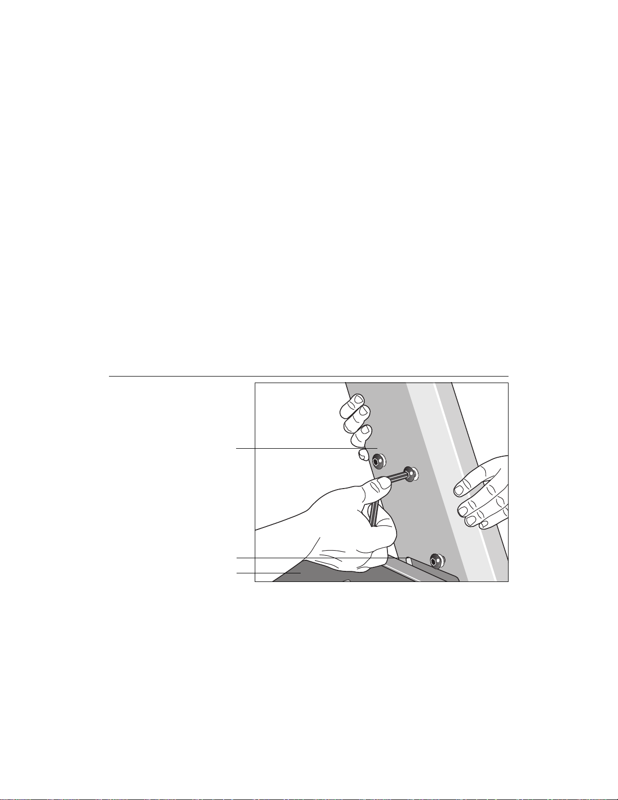
Diagram 12
Adjust the rear foot.
Important: If you need to make adjustments, adjust one rear foot at a time.
Do not use the rear foot to raise or lower the unit more than 1/4” in height.
Check the level of the unit after each adjustment.
15 T o adjust a rear f oot, locate the nut that secures the rear foot to the dec k. See
Diagram 12. Loosen the nut with a crescent wrench or appropriate open-end
wrench until you can easily turn the foot. See inset in Diagram 12.
CAUTION: Ask for assistance to lift the rear of the unit slightly off
the floor. Lift the unit by its side rails. Trying to lift the unit and adjust
the rear foot without assistance may cause injury to yourself or damage to the unit. Do not try to lift the unit using the running belt.
16. To raise the rear deck, turn the foot clockwise and make the proper height
adjustment. Then, retighten (counterclockwise) the nut securely using the
wrench.
TURNING THE UNIT ON AND OFF
Use the ON/OFF (I/O) power switch to turn the unit ON and OFF. This switch is
located on the front of the unit, near the power cord.
The treadmill requires a dedicated circuit. Plug the power cord into a dedicated
20 amp, grounded, power source. Make sure that no other product or machine
uses the same circuit as the treadmill.
CAUTION: Never remove or bypass the 3-prong plug on the unit’s power
cord with an adapter. Do not use a non-grounded outlet. Do not plug the
treadmill into a power transformer in an attempt to adjust the voltage
requirements.
T o complete the installation of the treadmill, continue to
the Running Belt.
page 18
Checking the Alignment of
Page 19

COMMERCIAL PRODUCTS DIVISION
CHECKING THE ALIGNMENT OF THE RUNNING BELT
The belt is aligned at the factory before shipment. However, during shipment or
by using the treadmill on an uneven surface, the belt might move off center.
Proper belt alignment is important because it allows the belt to remain centered
and assures smooth operation.
Follow these steps to check the alignment:
CAUTION: Do not walk on the running belt during this procedure.
1. The treadmill has adjustable rear feet. Check to make sure that the running surface is level (refer to steps 14 - 16 on the previous pages). If the
treadmill is placed on a slightly uneven surface, adjusting the rear feet
can help, but will not compensate for extremely uneven surfaces.
2. Locate the ON/OFF (I/O) switch at the front of the treadmill and turn ON (I)
the unit.
Note: Stand beside the treadmill and press Quick Start. The running belt starts
automatically after the message, “
Belt Starting 3, 2, 1,...
” appears.
3. Continue standing next to the treadmill and hold down the Speed ▲ key
until the display shows a speed of 3 miles per hour (5 kph).
4. Walk around to the rear of the treadmill and observe the belt for a few
minutes as it moves.
If the running belt,... Then,...
tracks centered on the running surface the belt is functioning correctly
(evenly distributed between the side rails) and no adjustment is necessar y.
runs or drifts off center you need to adjust the belt; see
Aligning the Running Belt,
page 42.
Important: If you notice that the belt needs alignment, make the adjustments
at once. Failure to do so might cause the belt to tear or fray which is not
covered by the Precor limited warranty.
5. To stop the r unning belt, press the red STOP button.
If the belt is functioning correctly, the treadmill is ready to use. Please continue
on to
Club Information
to learn how to customize the treadmill for your Club.
page 19
Page 20
COMMERCIAL PRODUCTS DIVISION
Club Information
These next few pages provide information that lets you customize the treadmill for
your Club. It is not information that your customer needs or, necessarily, should
see. This section co vers the f ollowing inf ormation about how to:
• determine which language appears on the display
• set maximum speed, workout, and pause times
• design custom courses
• display the odometer and other useful information
• connect to CSAFE compatible devices
Note: If your customers are interested in the learning more about the C956 or C954
treadmill, you may wish to direct them to the manual a vailable on Precor’ s web site
(www.precor.com). (The manual that appears on the web site does not contain the
information found in this section.)
Diagram 13
Display console keypad.
R
E
S
E
1
T
2
I
N
C
L
I
3
N
4
E
Note: The CHANGE key is not shown in this diagram.
Refer to Diagram 15 for its location.
CHANGING THE CLUB SETTINGS
The Club “custom” settings are accessed through specific codes that help eliminate unauthorized access. Refer to Diagram 13 to locate the keys. Information
that you can access and features that can be customized are as follows:
• Language — Choose to display English, German, Spanish or French.
• Units of Measure — Select between U .S. Standard and Metric displa ys.
• Maximum Speed — Determines the maximum speed that a user can select.
Selections range between 0.5 to 12 mph (1 - 20 kph).
• Maximum W orkout Time — Sets a maximum limit on workout time.
Note: Remember that the user will get an additional 5-minute cool down period
appended to a completed course. So, adjust the maximum time limit accordingly .
• Maximum Pause Time — Sets the maximum duration in which a person
can “pause” his or her workout.
• Custom Course 1 and 2 — Provides 2 courses that can be customized for
a specific user or general club purpose.
• Odometer , Hour s of Use, Software Version, and Error Log —The treadmill
stores the cumulative miles or kilometers, the number of hours that the unit has
been in use, the software version and software type (which is valuable when
calling customer service), and an error log (useful when troubleshooting).
page 20
Numerical pad disabled while in
Club Custom mode.
R
5
7
6
D
E
E
P
S
L
O
R
T
N
O
C
0
9
8
E
T
N
E
Gently , press and hold the
▼ or ▲
key to view the
available selections.
Page 21

COMMERCIAL PRODUCTS DIVISION
To access the Club settings, the following must occur:
❑ Check to be sure that the treadmill is turned ON.
❑ Check that the Precor banner appears on the display.
❑ Press the appropriate ke y sequences. (To cancel entries, press Reset.)
Important: T o access Custom mode, press Stop while the Precor banner is displayed.
Within 1/2 second, begin pressing the key sequences. If the system does not detect a
key press (within 1/2 second) after Stop, it resets to the Precor banner . When you begin
entering a key sequence, each key must be pressed within 4 seconds of the other or
the Precor banner reappears and you have to begin again.
Display key functions within the Club Custom Mode
▼▲ lets you scroll through the
various selections that appear.
Stop advances to the next aspect
of the program without storing
the information that appears on
the display.
Note: The touch sensitive keys can be gently pressed and held to view several
selections. The longer the ke y is held down, the faster the numbers scroll past.
The display console keys that you need to press to change the language,
select the units of measure, set the maximum speed, workout, and pause
times, or change the Custom courses are as follows:
Begin at the Precor banner and press the STOP key. Then, within 1/2 second,
initiate the key sequence below .
Speed ▼, Speed ▲, Speed ▼, Reset, Speed ▼, Speed ▲, Speed ▼
SELECTING THE LANGUAGE
Display prompts can appear in English, German, Spanish or French. Use the ▼▲
keys to make your choice and press Enter to select it.
Change reminds you what part of
the program you’re changing.
Reset exits Club Custom mode and
displays the Precor banner.
Enter saves the information being
displayed and moves to the
next aspect of the program.
Note: The functions of the displa y console k eys while in Club Custom mode are
described in the box above.
DETERMINING THE UNITS OF MEASURE
Two different units of measure can be selected,
your selection using the ▼▲ keys. Press Enter once the correct unit is displayed.
Note: Anytime you wish to exit the Club Custom mode, press the Reset key.
The display attributes that you selected by pressing Enter are saved and
recorded in memory.
Metric
or
U.S. standard
. Make
page 21
Page 22

COMMERCIAL PRODUCTS DIVISION
DETERMINING THE CLUB SPEED LIMIT
Y ou can set the maximum speed f or the treadmill. This limits how f ast the running belt
moves and, consequently , how many adjustments a user can mak e to the treadmill’s
speed. The speed is displa y ed in miles per hour (mph) or kilometers per hour (kph)
depending upon the units of measure (Metric or U.S. standard) that are selected.
The ▼▲ keys let you choose a speed between: 0.5 to 12.0 mph
1.0 to 20.0 kph
Important: If you select a number that limits the miles per hour, y our change
not affect
the speed entered in miles per hour (U.S. standard) to k ilometers per hour (Metric).
It stores separate numbers for the different units of measure.
CAUTION: If you change the Unit of Measure display, be sure to check the
“Set Max Speed” setting to verify that it is correct.
the kilometers per hour (and vice versa). The treadmill does not con vert
will
SETTING A WORKOUT TIME LIMIT
You can limit how long a user works out by setting a duration between 1 and
240 minutes. The treadmill also lets you choose “no limit” which allows the
user to select a course and work out indefinitely.
Note: The Quick Start program is automatically limited to 30 minutes. However, if a user presses Quick Start at the Precor banner, and the Club program has limited Workout Time to less than 30 minutes, than that duration
takes effect.
Use the ▼▲ keys to select a workout time limit. For example, if you set the
workout time limit to 20 minutes, the treadmill allows users to specify a workout
between 1 and 20 minutes. Users cannot specify a time longer than 20 minutes.
Note: Take into account the user will get an additional 5-minute cool down period
appended to his or her workout, so adjust the maximum time limit accordingly.
SETTING A PAUSE TIME LIMIT
Setting a Pause time limit is useful because the treadmill returns to the Precor
banner at a selected interval after the Stop key is pressed whether the user
planned to return or not.
Use the ▼▲ keys to set a P ause time limit between 1 and 120 seconds (2 minutes).
page 22
Page 23

COMMERCIAL PRODUCTS DIVISION
CHANGING THE C956 CUSTOM COURSES
Note: This aspect of the Club Custom mode does not appear in the C954 treadmill.
T wo custom course progr ams (Course 1 and Course 2) exist in the C956 treadmill.
After you modify Course 1 (or opt to bypass it), Course 2 appears on the displa y .
The keys on the console keypad have a different function than explained in the
box on page 21. In the Custom Course programs, the keys function as follows:
Custom Course Program Keys
Speed ▼ or ▲ moves the blinking LED from column to column.
Incline ▲ or ▼ affects the incline of the selected column.
Enter accepts any changes and stores the course in memory.
Stop or Reset exits the course (leaving it unchanged) and resets the
display to the Precor banner.
If you decide to select a custom course, you have the ability to create a new,
or “draw over” an existing, course profile. The entire course appears on the
display. A blinking LED appears at the top of the far left column and indicates
the starting position. Any incline changes that you make occur only in that
column. The treadmill’s speed is determined by the user.
Begin modifying the course profile one cell at a time using any Incline ▲ or ▼
key. The available incline range is from 1 to 12%. To move onto the next column,
press any Speed ▼ or ▲ key. (Refer to the chart above.)
When you have finished making changes, press Enter to save the course
profile. The display moves to the next Custom Course (#2) or returns to the
Precor banner (depending on which Custom Course you were modifying).
Note: To exit the custom course mode without saving any of the changes, press
Stop or Reset. The custom course that existed prior to your changes is re-
instated and the display returns to the Precor banner.
page 23
Page 24

COMMERCIAL PRODUCTS DIVISION
VIEWING THE ODOMETER, HOURS OF USE, SOFTWARE
VERSION AND ERROR LOG
Start at the Precor banner and press the Stop key. Then, within 1/2 second,
initiate the following key sequence.
Speed ▲, Speed ▼
The field name Odometer appears briefly and then the odometer value (the
cumulative distance users have travelled) appears in miles or kilometers.
Press Enter and the number of hours (Hour Meter) that the unit has been in
use appears. The treadmill notes the passing of each 10th of an hour, but the
numeric value that appears is truncated to the nearest full hour.
Press Enter again and the unit’s three digit Software Version (upper and
lower) appears on the display.
Press Enter once again and the Error Log appears. Press any ▼ or ▲ key to view
the error messages. T o return to the Precor banner, press Enter, Stop, or Reset.
Note: T o clear (delete) the error log, press Quick Start for at least 4 seconds
while viewing the list. Prompts appear on the display and let you know when
the error messages have been deleted (“cleared” from memory).
Important: You cannot retr ieve the error log once you have deleted it.
USING CSAFE ST ANDARD EQUIPMENT
The C956 and C954 are fully compatible with CSAFE protocols. If the unit is
connected to a CSAFE master device, the user will be prompted to enter a
user ID. Five zeros appear on the display. The left zero blinks to indicate that it
is awaiting input. The following table provides information about the keypad
functions:
User ID Entry: Program Keys
Speed ▼ or ▲ moves the blinking LED from field to field.
Incline ▲ or ▼ changes the number value in the selected field.
Number keypad use the number keys to enter a user ID. The number that is
pressed appears in the display and the next field begins to
blink. When all 5 user ID numbers are selected, the user
must press Enter to submit it.
Enter submits the displayed user ID. Note that if the 5 zeros are
being displayed when the user presses Enter, user ID.
entry is bypassed and the Course prompt appears.
Reset resets the display to the Precor banner .
page 24
A message indicates when the user ID is accepted by the CSAFE master
device. Then, the Course prompt is displayed. See
Out
on page 34.
Quick Steps to Working
Page 25

COMMERCIAL PRODUCTS DIVISION
The C956/C954 Display
The C956 or C954 is designed so users can work out with minimal instruction or
training. The directions on the console and the prompts on the display will guide a
user through the entire workout session. Bef ore the treadmill is used, how ever, we
recommend that you familiarize yourself with it so you can instruct your customers to use it safely and effectively. This section covers the following information:
• an overview of the features provided on the display console
• an explanation about the available courses
• instructions for utilizing the heart rate options
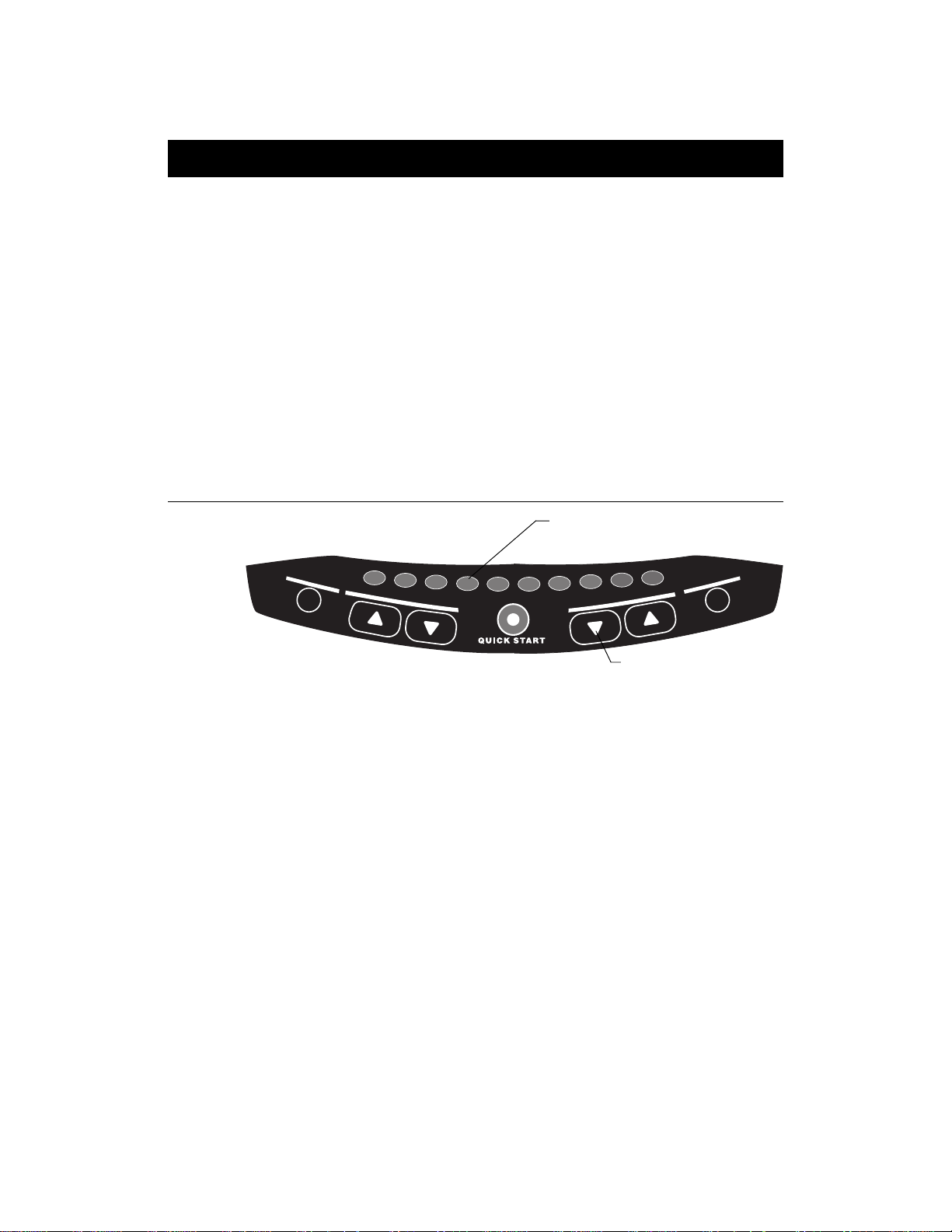
FEATURES ON THE DISPLAY CONSOLE
Indicator lights show you which f eature is being display ed. When you are working out, the display presents Time, Distance, Speed, and Calories. You change
what features appear on the display by pressing the Change keys.
Diagram 14
Smart Rate® bar graph
Banner and course
profile display
(LED matrix)
During course
selection, the course
# appears here.
Numeric keys can be
used to answer prompts
and select incline and
speed levels in a
course.
C956 Display Console
C956
SmartRate
Above
Heart Rate
Zone
CAUTION
Keep hands and clothing away from
bed, belt, and rear roller when treadmill is in
operation. Do not allow children and people
unfamiliar with treadmill operation on or near the
treadmill. Never stand on the belt when starting
the treadmill. Stand on the side platforms.
Never attempt to turn around on the moving
belt. Read owner's manual before operating.
Before beginning any fitness program, you
should have a complete physical examination
by your physician. If you feel faint or dizzy, stop
exercising immediately.
SPEED
METS
OFF
8
7
6
C
D
E
E
P
S
O
T
N
CALORIES
CAL PER MIN
OFF
9
L
O
R
© Copyright 1999 Precor Inc.
0
N
E
R
E
T
R
E
S
E
T
Cardiovascular
Weight Loss
Zone
Zone
Below
Zone
TIME
SEGMENT TIME
PACE
CHANGE CHANGE CHANGE CHANGE
1
2
I
DISTANCE
INCLINE
OFF
3
4
N
C
L
I
N
E
5
QUICK START
As you exercise, the display console provides motivation by presenting constant
feedback about your progress. An brief explanation of each feature on the display
console appears in Diagram 14. Look on the next page for a more thorough explanation.
If a heart rate is
detected, it is
displayed in this
window.
Workout statistics
display (alphanumeric)
Change keys let you
choose what information
to display.
Smart T ouchTM keys
(used to input or select
data and control the
workout session)
Note: If an error message appears, call a Precor qualified service technician or service
center. For the service center nearest you call, 1-888-665-4404.
page 25
Page 26

COMMERCIAL PRODUCTS DIVISION
TOP DISPLA Y WINDOWS
Smart Rate®: You must enter your “Age” (during the course Setup prompts), and
wear a POLAR® chest strap, while in a course program, before the blinking segment in the bar graph can show the zone that your heart rate is in, either: W eight
Loss or Cardiovascular .
Weight Loss Zone: Maintaining your heart rate between 55% and 70% of
your maximum aerobic heart rate, helps burn enough calories that, when
continued on a regular basis for 30 minutes or more, provides the greatest fat-burning results.
Cardiovascular Zone: Maintaining y our heart rate between 70% and 85%
of your maximum aerobic heart rate, helps you (when continued on a
regular basis for 30 minutes or more) improve your overall cardiovascular/cardiorespiratory fitness level.
Important: During a course, your heart rate must be above 40 beats per
minute before the segment begins to blink. If your club has the heart rate
touch-sensitive electrodes on the handrail, you don’t need to wear a
POLAR® chest strap. However, you will need to grasp the electrode strips.
Note that pressing Quick Start disables the Smart Rate® display feature .
HEART RATE: The heart rate display lets you monitor your heart rate. When a
heart beat is detected, the number appears in the small upper right display
(refer to Diagram 14) and blinks in time with y our pulse . If you did not purchase
the Precor Heart Rate Touch option or are not wearing a POLAR® chest strap,
your heart rate will not be detected and no pulse rate appears.
CENTER DISPLAY WINDOW (C956 only)
The Precor banner and course profiles appear in the large center display (LED
matrix). Always start a workout at the Precor banner. During workouts, the
course profile appears in the center display and corresponds to the program
you selected. As you proceed through your workout, your position is indicated
by a blinking cell.
ELONGATED CENTER DISPLAY (C956 and C954)
Prompts appear in this display prior to your workout. You address each prompt
using the numeric or keypad keys. Once you begin a workout, lights appear in
the columns below the window indicating which information is being displayed.
You can highlight a particular feature by pressing the appropriate Change key.
The following describes the information that can appear in the display.
TIME: During your workout, a time (0:00) display appears when you begin working out. Time appears in minutes and seconds. However, should you exceed 60
minutes (during a single workout), the Time display conver ts to hours and minutes. Usually, the Time display shows how long you’ve been working out. However, in warm-up and cool-down periods, the Time display indicates the min utes
remaining. This also occurs in a course that has a specified duration.
page 26
Page 27

COMMERCIAL PRODUCTS DIVISION
DIST ANCE: The distance that you ha ve trav elled appears (00.00) once you begin
a workout. Distance appears in 100th mile increments. Distance can appear in
miles or kilometers. If you wish to change the display, follow the instructions
found in
Club Information
on page 20.
SPEED: Displays the running belt’s speed. The ▼ and ▲ k eys let you decrease or
increase the treadmill’s speed. The maximum speed can be set by the club (see
Club Information
on page 20). The running belt speed ranges from 0.5 to 12 mph
(0.8 to 20 kph). You can also use the numeric ke ys to designate the speed, once the
running belt is moving. Refer to Numeric Keys and Speed ▼▲ on page 29.
Note: You can check the speed (when it is not the chosen displa y) any time during
your workout by lightly pressing either Speed ▼ or ▲ key (for less than 2 seconds). Pressing the Speed ▼ or ▲ key for more than 2 seconds causes the
treadmill’s speed to change.
CALORIES: Provides the cumulative number of calories being burned by the user.
SEGMENT TIME: Indicates the amount of time, in minutes and seconds
(mm:ss), that remain in the highlighted column (or segment) before the cell at
the top of the next column begins blinking.
INCLINE: Displa ys the percent of incline during your workout. The Incline ▲ and
▼ keys aff ect the treadmill’ s lift and let y ou set an incline between 0% and 12%.
The values displayed can change (in 1/2% increments).You can also use the numeric keys to designate the incline, once the course has begun. Refer to Nu-
meric Keys and Incline ▲▼ on page 29.
Note: You can check the incline (when it is not the chosen display) any time
during your workout by lightly pressing either Incline ▲ or ▼ key for less than
2 seconds. Pressing the Incline ▲ or ▼ key for more than 2 seconds causes
the treadmill’s incline to change.
METS: Displays the metabolic units associated with your workout.
CALORIES PER MINUTE : Indicates the approximate number of calories being
burned per minute.
PACE: Displays your target speed in minutes and seconds per mile (or kilometer).
page 27
Page 28

COMMERCIAL PRODUCTS DIVISION
KEYS ON THE DISPLA Y CONSOLE
The Precor Smart TouchTM treadmills have an easy-to-use keypad that is activated by the slightest touch. Remind users that they only need to apply gentle
pressure to these ultra-sensitive keys.
Each key on the display console’s keypad provides specific functions. Numeric keys (numbered 1 - 0) let you enter data in ans w er to the display prompts
and change the speed during a workout. The standard keys, Change, Reset,
Incline ▲▼, Speed Control ▼▲, and Enter, let you enter data as well as
control your workout.
The following information explains the different uses of the keys from left to
right. To locate each key, look at the display console or refer to Diagram 15.
Diagram 15
Display console keypad.
Quick Start: Bypasses the remaining
Setup prompts and starts moving the
running belt. Smart Rate® is inactive and
default values apply .
Note: The CHANGE key is not shown in this diagram. Refer to Diagram 14 for its location.
KEYPAD TIPS
• Accurate entries are required or features such as Smart Rate® will not
work properly.
• Answer the Setup prompts using the numeric keys or by pressing the ▼ or
▲ keys.
• Press Enter to select the information being displayed.
Numeric keys: Indicate course #,
time limit, or goal entries. During a
workout, use these keys to select
a target Speed or Incline.
R
E
S
E
1
T
2
3
4
5
I
N
C
L
I
N
E
6
8
7
D
E
E
P
S
0
9
L
O
R
T
N
O
C
R
E
T
N
E
page 28
• Quick Start bypasses further selections and causes the running belt to
start moving. Default values apply (see QUICK START on page 30). The
Smart Rate® display does not appear.
• A time-out occurs during the Setup prompts if the treadmill detects no key
presses for 2 seconds. The display returns to the Precor banner.
• Press Reset to return to the Precor banner.
• The Stop key does not appear in Diagram 15, but its function is vital as
explained in this section.
Page 29

COMMERCIAL PRODUCTS DIVISION
Numeric Keys (1 - 0): During a workout, you can use the numeric keys to change
the treadmill’s speed or incline (in whole numbers or increments). The range of
speed (0.5 - 12 mph, 1 - 20 kph) can be set by the club, so there may be limits.
Check with the club manager . Remember , if you use the numeric ke ys to change
the speed or incline, you need to designate which function you are changing by
pressing the Speed ▼ or ▲ key (or the Incline ▲ or ▼ key) within 3 seconds.
Note: When you use the numeric keys to change the incline, the actual incline
appears on the display as the lift moves toward the target position. If you wish to
halt the lift’s mo v ement, press either the Incline ▲ or ▼ k ey. The lift stops moving
and the display shows the current incline level. A similar situation occurs when you
use the numeric keys to change the speed, only it’ s the running belt that is being
affected.
During the Setup prompts, you can also use the numeric keys to type in a course
number, work out time, “goal” entry, and age. Note that you must press Enter to
process your selection.
CHANGE: During a workout, the Change key lets you choose which feature
appears on the display.
RESET: While you are answering the Setup prompts or when the running belt
is stopped, you can cancel the program, clear the display, and return to the
banner by pressing Reset.
INCLINE
▲▼▲▼
▲▼: During a workout, the Incline ▲▼ keys let you increase or de-
▲▼▲▼
crease the running bed’s incline. The incline changes can range from 0% to 12% in
0.5% increments. The incline in some courses (Custom, Random and Interval) is
preset, but can be overridden by the user. In the Heart Rate and Weight Loss
courses, the incline may change automatically to maintain a designated target
heart rate.
When you press the Incline ▲▼ keys, the number that appears on the display
shows the target incline (not the actual incline) because the display can change
much faster than the motor driven lift.
Another feature of the Incline ▲▼ keys lets you review the treadmill’s incline
any time during your workout. If INCLINE is not one of the chosen features
being displayed, you can view the actual incline by lightly touching either
Incline ▲ or ▼ key. You can opt to change the incline, if you hold the key
down for more than 2 seconds.
Note: The numer ic keys can also be used to adjust the incline. Please refer to
Numeric keys
above.
STOP: When the Stop key is pressed, the running belt slows to a gradual stop .
The treadmill remains in Pause mode. If the lift was moving when the Stop key
was pressed, the lift stops also and remains at its current incline level.
To resume a workout, the Speed ▲ must be pressed. If no key press is detected
and the Pause time limit elapses, the display returns to the Precor banner. A
default time limit of 2 minutes exists or a “Pause time limit” can be set by the club,
refer to
Club Information
on page 20.
page 29
Page 30

COMMERCIAL PRODUCTS DIVISION
Important: As a safety feature, a sharp tug on the security cord that is attached
to the Stop key will cause the running belt to stop. It is a requirement that a user
attach the security clip on his or her clothing while working out. Please refer to
Using the Security Clip
on page 32.
SPEED CONTROL
▼▲▼▲
▼▲: The Speed ▲ key initiates the movement of the run-
▼▲▼▲
ning belt at the beginning of a course and lets you designate the target speed.
During a workout, the Speed ▼▲ keys let you increase or decrease the running
belt’s speed. Speed changes can range from 0.5 to 12 mph (1 to 20 kph) in
0.1 increments. The speed in the Interval course can be programmed by the
user. The speed of the running belt can also be modified and limited by the club.
Check with the club manager or refer to
Club Information
on page 20.
Note: When you press the Speed ▼▲ key, the number that appears on the
display shows the target speed and may differ slightly from the actual speed
because the display can change much faster than the running belt. Eventually,
the two meet at the target speed.
Another feature of the Speed ▼▲ keys lets you review the treadmill’s speed
and pace any time during your workout. If SPEED and/or PACE is not one of
the chosen features being displayed, you can view the speed of the running
belt and your pace by lightly touching the Speed ▼ or ▲ key. A 2-second
display lets you review your speed and pace. You can opt to change the speed,
if you hold the key down for a few more seconds.
Note: The numeric keys can also be used to adjust the speed. Please refer to
Numeric keys
above.
QUICK START: Quick Start lets you bypass the Setup prompts and start your
workout immediately using the Manual course.
Default values apply.
page 30
QUICK START Default Values
Prompts Default V alue
Course Manual
Time 30 minutes: Or, the Club limit whichever is less. Weight
Loss course is fixed at 28 minutes.
Distance Goal 3 miles (5 kilometers)
Calorie Goal 300
Weight 150 lbs. (68 kg.)
Age 0 : An Age entry must occur to utilize the Smart Rate
display. If Quick Start is pressed
after
an
Age
is entered,
®
then the Smart Rate® display will appear when you hold
onto the heart rate “touch” sensors on the handrail or wear
the POLAR® chest strap. If no
Age
entry occurs, the Smart
Rate® display lights up, but no blinking sensor appears.
Note: The heart rate “touch” sensors on the handrail are an option available
through your Precor dealer.
Page 31

COMMERCIAL PRODUCTS DIVISION
The Quick Start key can be pressed any time during the Setup prompts. Default
values apply after that point. See the table below:
Press Quick Start at the,... The following occurs:
Precor banner You bypass the Setup prompts. A message
appears,
Belt Starting 3, 2, 1,...
and your
work out begins in Manual mode.
Course prompt The displayed course is accessed.
Workout Time prompt The time that appears on the display be-
comes the workout time limit.
Distance Goal prompt The displayed number is set as a distance
(C956 only)
goal. This prompt only appears when the
Distance Goal course is selected. Allow-
able distance entries: 0.1 to 50.0 in miles
(or kilometers).
Calorie Goal prompt The displayed number is entered as the
(C956 only)
calories goal. This prompt only appears
when the Calorie Goal course is selected.
Enter between 1 to 5000 calories.
W eight prompt The weight that appears on the display be-
comes your designated weight that the
treadmill uses to compute statistics. Accept-
able entries: between 0 and 999.
Age prompt The age that appears on the display
becomes the your designated age that the
treadmill uses to compute statistics. A
correct age entry between 0 and 99 is very
important if you plan to utilize the heart
rate characteristics of the treadmill. The
Quick Start key acts the same as the
Enter key at this point because you have
answered all the Setup prompts.
ENTER: Workout specific prompts need to be answered and “entered” into
memory. Pressing Enter selects the information displayed and processes it.
page 31
Page 32

COMMERCIAL PRODUCTS DIVISION
Exercising on the Treadmill
Once the C956 or C954 is set up, it is ready to use. There are no complex instructions to follow or mandatory programming steps required to operate the treadmill.
The easy-to-understand prompts let you select a course and specify how long you
want to work out. Begin working out and then, adapt the speed and incline level to
meet your fitness goals.
CAUTION: Before beginning any fitness pr ogram, have y our physician give
you a complete physical examination.
USING THE SECURITY CLIP
A security clip is attached by its cord to the red Stop button that straddles the
handrail.
out.
stop. If the security switch trips while you are working out, the treadmill retains
your workout statistics and enters Pause mode. To resume your workout, re
attach the security clip to your clothing, and press the Speed ▲ key until you
reach the desired speed.
Always attach the security clip to your clothing before each work-
A tug on the cord trips the security switch and slows the running belt to a
Important: Club owners, managers, personal trainers. Remind users how
important it is to use the security clip while working out on the treadmill. Instruct
them on how to attach it to their clothing near their waistline. If any complications occur, a strong tug on the security cord will stop the running belt.
Note: A velcro patch is located on the right side of the console by the handrail.
Use it to store the clip while the treadmill is not being used.
PAUSE, COOL DOWN, SUMMARY AND EXIT FEATURES
Pausing, cooling down, and exiting are integral parts of your workout and can
be accessed any time during a course. The treadmill goes through several
prerequisites before actually exiting a course. The following tables explain the
different conditions or situations that apply.
In a course,
you press This is what happens...,
Stop Enter Pause mode. The running belt slows to a gradual stop.
Note that you may also press the Speed ▼ key until zero
appears on the display. Once the running belt stops, TIME
stops accruing. The display features remain, so you can
review your workout statistics. The factory setting for Pause
mode is 2 minutes (120 seconds). The club has the option to
change the setting. A duration can be set between 1 and 120
minutes and limits how long a user can pause his or her
workout. Refer to
Club Information
on page 20.
page 32
Page 33

COMMERCIAL PRODUCTS DIVISION
In Pause mode,
you press This is what happens...,
Speed ▲ Exits Pause mode and starts the running belt moving again
so that you can resume where you left off.
Reset Displays the Workout Summary banner. You can scan
through your workout statistics (TIME, DISTANCE,
CALORIES) by pressing the Change key. Note that the TIME
display shows the accumulated workout time including warmup and cool down periods. To exit the summary state, press
Reset again or wait until the time limit (2 minutes) elapses.
The display returns to the Precor banner.
Note: The factory setting for Pause mode is 2 minutes (120 seconds). The club
has the option to change the setting. A duration can be set between 1 and 120
seconds and limits how long a user can pause his or her workout. Refer to
Club Information
on page 20.
In Cool down,
you press This is what happens...,
Stop Enters Cool down - Pause mode. The running belt slows to
a gradual stop. TIME stops counting. The display features
remain, so you can review your workout statistics. Note
that the Pause mode has a time limit and the club has the
option to change the setting. If you enter Pause mode during your cool down, it is of limited duration.
Speed ▲ Star ts the running belt moving again and returns to the
cool down mode, so that you can resume where you left
off. TIME continues to count down.
Reset Displays the Workout Summary banner. See the informa-
tion under Pause mode.
At the Workout
Summary banner,
you press This is what happens,...
Reset Returns to the Precor banner. When you complete the cool
down period (or exit from a paused mode by pressing Reset),
the Workout Summary banner appears. Workout statistics
except TIME, DISTANCE and CALORIES reset to zero. (Note
that the TIME display shows the accumulated workout time
including warm-up and cool down periods.) You are given 2
minutes to review your workout statistics before the display
automatically resets to the Precor banner. You can also press
Reset, to return to the Precor banner.
page 33
Page 34

COMMERCIAL PRODUCTS DIVISION
QUICK STEPS TO WORKING OUT
The steps to working out on the C956/C954 are listed below . A short explanation
appears on the left with the more thorough description following on the right.
CAUTION: Before beginning any fitness pr ogram, obtain a complete ph ysical examination from your physician.
WORKOUT TIPS
• Always attach the security clip to your clothing prior to working out.
• Check that the unit is turned ON. The I/O switch is located at the front.
• Answer Setup prompts using the numeric keys or by pressing the ▼ or ▲ keys.
• Press Enter to select the information being displayed.
• Quick Start bypasses further selections and starts the running belt. Default
values apply (see QUICK START on page 30). Smart Rate® is not active.
• A time-out occurs during the Setup prompts if the treadmill detects no key
presses for 2 seconds. The display returns to the Precor banner.
1
Put on the chest strap.
(Available with the Precor Heart
Rate Option.)
2
Straddle belt.
3
Attach security clip
to clothing.
CAUTION: Hold onto
the handrails if you
press the Quick Start
key . The running belt
starts automatically.
4
Select a course.
5
Begin working out.
Enter the course selection,
answer prompts, and enter
your Weight and Age.
1. For your Heart Rate to appear on the display, you need to
wear a POLAR® chest strap or hold onto the touchsensitive electrode strips on the handrail.
2. Straddle the running belt with your feet firmly planted on
the right and left staging platforms. (Stand close enough
to the display console so that you can extend your arms
to easily touch the keys.)
3. Attach the security clip to your clothing near your waistline where it will not interfere with your workout.
4. On the C954, to begin your workout, press Quick Start.
On the C956, to display the course selections, press any
▼ or ▲ key or use the n umber ke ys and then, press Enter.
C954 — Manual course only. For default values, see QUICK
ST ART on page 30.
C956 — The 21 courses that are available appear on the
label attached to the display console. Brief course descriptions are provided beginning on page 36.
5. The next displays are dependent on the type of course that
you select. Then, you are prompted to enter your WEIGHT
and AGE. Follow the instructions on the display. You may be
prompted to answer more questions or press the Speed ▲
key to begin your workout. Hold onto the handrail with one
hand while you press Speed ▲ with the other hand. Step
onto the running belt while the speed is at 1 mph (2 kph).
Once you are comfortable with the walking or running speed,
you can remove your hands from the handrail.
page 34
Note: Any time during the Setup prompts, you can press
the Quick Start key. Refer to QUICK ST ART on page 30.
Page 35

COMMERCIAL PRODUCTS DIVISION
6
Continue your
workout.
7
End your workout.
(Review Workout Summary)
Remove the security clip
8
and step off the treadmill.
(Pause)
(Cool down)
To pause during your workout session before finishing the
selected course, press the Stop key . See
Summary and Exit Features
for more information.
Pause , Cool Down,
6. When you have completed a course, a 5-minute cool down
period automatically begins. Hold onto the handrail. You
can exit a course prematurely or access the cool down
period prior to the end of a course using the keys on the
keypad. Refer to
Features
on page 32.
Pause, Cool Down, Summary and Exit
Note: Always incorporate a cool-down period into your workout. See
Cooling Down After Your W orkout
.
7. After you complete the 5-minute cool down period, the
running belt comes to a complete stop and a Workout
Summary banner appears. W o rk out statistics except TIME,
DISTANCE and CALORIES reset to zero. (Note that the
TIME display shows the accumulated workout time including warm-up and cool down periods.) You are given 2 minutes to review your workout statistics before the display
automatically resets to the Precor banner. You can also press
Reset, to return to the Precor banner.
8. Detach the security clip from your clothing and carefully
step down from the treadmill.
COOLING DOWN AFTER A WORKOUT
Cooling down is an important aspect of your workout because it helps reduce muscle stiffness and soreness by transporting excess lactic acid out
of the working muscles. Cooling down for at least 3 minutes helps provide a
smooth transition that allows your heart rate to return to its normal (nonexercising) state. The treadmill automatically initiates a 5-minute cool down
period once you complete a course. A prompt appears, indicating that you
are in cool down.
During your cool down, the workout statistics continue to appear. The TIME
display counts down so you know how much time remains. When you complete the 5-minute cool down, a W orkout Summary banner appears. See the
information on page 32.
page 35
Page 36

COMMERCIAL PRODUCTS DIVISION
Courses
The C954 provides one Manual course while the C956 lets you choose between 21
variable courses. This section provides information about the special features and
functions of the treadmill’s courses and how to best utilize the:
• Smart Rate® feature • Manual course (C954/C956)
• Track course • Cross Country courses
• Aerobic courses • Gluteal courses
• Interval courses • Custom courses
• Random course • Hear t Rate course
• Weight Loss course • Goal-based courses
Note: To choose a course, begin at the Precor banner and press Enter. User-
friendly prompts guide you through the course selections. Refer to
Working Out
on page 34.
THE HEART RATE FEATURE
To use the heart rate features you must wear the POLAR® chest strap while
working out. The chest strap transmits your heart rate signal to the receiver
installed in the display console. The signal appears as your pulse rate on the
display. During your workout, the heart rate indicator lights and blinks at the
same rate as your pulse. This lets you see what your heart rate is doing even
when the display is presenting other workout statistics.
Quick Steps to
Note: The Smart Rate® display does not appear if you use the Quic k Start key to
access a course. Refer to Q UICK START on page 30.
UTILIZING THE SMART RATE
Add the benefit of Smart Rate® to every course on the treadmill. Using Smart Rate
as a visual cue helps you adjust your e xercise routine to suit specific needs. Smart
Rate® simplifies the correlation between heart rate and exercise. You don’t hav e to
stop concentrating on your workout to find your pulse. It is displayed right in front of
you along with the Smart Rate® zone. Once you begin a workout, a blinking segment in the bar graph appears on the left of the display, if you entered your age
during the Setup prompts. The blinking segment indicates the zone that y our heart
rate is in: W eight Loss or Cardiovascular.
Important: Access to Smart Rate® is only available when the person e x ercising
wears a POLAR® chest strap or uses the touch-sensitive electrode strip on the
handrail. (The POLAR® chest strap and the “touch” capability are separate purchase options.) The Smart Rate® indicator lights do not appear when Quick Start
is used to select a course.
®
FEATURE
®
page 36
Page 37

COMMERCIAL PRODUCTS DIVISION
Diagram 16
Training Zones
HEART RATE TRAINING ZONE
200
200
190
195
190
185
180
180
175
170
136
111
165
132
107
160
128
104
155
124
101
150
120
97
145
116
94
MAX.
HEART
RATE
80% OF
MAX.
HEART
RATE
65% OF
MAX.
HEART
RATE
170
160
150
140
YOUR HEART RATE
130
120
100
160
156
152
148
144
140
RECOMMENDED TRAINING ZONE
130
127
124
120
117
114
90
80
70
20
25 30 35 40 45 50 55 60 65 70 75
YOUR AGE
For the ideal “weight loss” range, y our heart rate should be between 55% and 70%
of your maximum aerobic heart rate. It should ne ver e xceed 80% of your maximum
aerobic heart rate or go above your training zone. Refer to
Diagram 16 for your appropriate training zone.
When you maintain your heart rate between 70% and 85% of your maximum aerobic heart rate, you are improving your ov erall cardio v ascular/cardiorespiratory fitness level. Maintaining your heart rate in either zone (weight loss or cardio vascular)
for 30 minutes or more on a regular basis (minimum 3 times a week) provides the
greatest benefits.
MANUAL MODE AND THE QUICK START KEY
Manual mode (C956 and C954) lets you control the incline and running belt
speed which affects the effort you put into your workout. As with other courses,
when you complete the time limit set for the course, the automatic cool-down
period begins.
You can choose Manual mode in two different ways:
• pressing the Quick Start key at the Precor banner. Quick Start bypasses
the remaining selections and starts the Manual course. Default values
include a time limit of 30 minutes (or the Club setting, whichever is smaller),
150 lbs. (68 kg.) and an age of 0. The Smart Rate® display is inactive .
page 37
Page 38

COMMERCIAL PRODUCTS DIVISION
• pressing Enter at the Precor banner . This causes the C954 or C956 to dis-
play several Setup prompts. At the course prompt, you select #1 — Manual
course.
The Manual course profile appears as a flat line. Use the ▼▲ keys or the numeric
keys to adjust the incline or speed. (See pages 29 and 30 for more information
on the different key’s function.) As you proceed with your workout, a blinking
cell represents your position on the course.
THE TRACK COURSE
The C956 Track course presents an oval as the course profile. The “lap” count
appears on the inside of the oval and a blinking segment indicates your position on the track. One loop around the track represents 440 yards (0.25 miles)
or 400 meters.
Y ou can contin ue (counterclockwise) around the track f or the duration of the course
(which can be limited by the club). The lap count that appears represents the
number of laps completed, plus the one that your on.
PREPROGRAMMED COURSES
In the C956 preprogrammed courses, the incline is predetermined. You can
make changes to the running belt speed (numeric keys or Speed ▼▲ keys)
throughout the course and even the preset incline can be overridden using the
Incline ▲▼ keys.
INTERVAL COURSE
The 3 interval courses on the C956 let you select the rest and work intervals
according to your training regimen. In the 1-3 interval course, each rest interval is
followed by 3 work intervals. In the 1-2 interval course, each rest interval is followed by 2 work intervals. In the 1-1 interval course, each rest interval is
followed b y 1 w ork interval. You set the incline and speed for first rest and work
interval and the software repeats the intervals throughout the course. At any
point during the workout, you can change the settings of the current interval by
simply pressing the ▼▲ or number keys. The software remembers the new
settings and applies it to the appropriate rest or work interval.
Important: If you entered your Age during the Setup prompts and wear the
POLAR® chest strap or utilize the “touch” heart rate, you can adjust the rest or
work intervals to keep your heart rate in its recommended zone. For the weight
loss mode, try to maintain your heart rate at the lower end (55% of maximum
heart rate) while in the “rest” intervals and keep it at 70% of maximum heart
rate while in the “work” intervals. See Diagram 16 on page 37.
page 38
Page 39

COMMERCIAL PRODUCTS DIVISION
T o use the interval course, take the following steps:
1. Follow the instructions on page 30,
2. At the course prompt, use the ▼▲ key or numeric keys to select course
12, 13 or 14 (depending on the interval length).
4. Press Enter to proceed to the next prompt. When you finish answering the
Setup prompts, the Interval course begins.
To set the incline and speed levels for each interval, take the following steps:
1. To program the rest inter val, press the Incline and Speed ▼▲ keys to
change the corresponding levels. When the desired settings are displayed,
simply continue working out—you do not need to press Enter.
The C956 returns to the “rest” settings at the beginning of each rest interval until you readjust it or end your workout.
2. The same procedure applies to specify the settings for the work interval.
The value that appears in the SEGMENT TIME field indicates the time remaining in the current interval. Each time the C956 changes intervals, it infor ms
you by displaying a message. When you complete the time limit set for the
course, the automatic cool-down period begins.
CUSTOM COURSES
Two custom courses exist on the C956. The incline on these courses can be
preset by the club. Refer to
Quick Steps to W orking Out
Club Information
.
on page 20.
RANDOM COURSE
The C956 Random course is similar to the preprogrammed courses in that it’s
incline is preset. However, the differences include, a “0%” incline for the first
segment (column) and a maximum incline of 9%. The maximum range that the
incline can be changed is fixed at + or - 4%. Every time a user chooses this
course, the course profile changes.
page 39
Page 40

COMMERCIAL PRODUCTS DIVISION
HEART RATE COURSE
Once you set your target heart rate and the running belt’s speed, the C956
Heart Rate Course monitors your heart rate and automatically maintains it
within a few beats per minute (bpm) of the selected target. Blinking lights on
the Smart Rate® bar graph appear to show the “zone” that you are in.
Note: For the C956 to detect a heart rate, the user must wear the POLAR
chest strap or hold onto the touch-sensitive electrode strips on the handrail.
The POLAR® chest strap and touch-sensitive handrails are optional equipment
that can be purchased from your dealer.
To use the Heart Rate Course follow the steps found in
Out
(page 30) and choose the appropriate program number at the Course
prompt. (Age
must
be entered during the Setup prompts.) Once you have
Quick Steps to Working
finished answering the remaining Setup prompts, the following occurs:
• The software verifies that it detects a heart rate signal. You need to press
the Speed ▲ key to begin your workout.
Note: If your heart rate cannot be detected (or transmitted through the
POLAR® chest strap or touch-sensitive handrails), three dashes (- - -)
appear in the Heart Rate display .
• The treadmill provides a 3-minute warm-up period before entering the
Heart Rate Course. During this time, you may make changes to the target
heart rate by using the Numeric keypad or Incline ▲▼ keys. Use the
Speed ▼▲ keys to set the running belt’s speed.
Note: If your heart rate moves into the heart rate zone for y our age during the
3-minute warm-up period, the Heart Rate Course begins concurrently .
• After the warm-up period, the treadmill automatically adjusts the incline to
keep your heart rate at the selected target. Check the Smart Rate® display
to see if you are in your preferred zone (cardiovascular or weight loss).
®
page 40
Note: You can change your heart rate or speed anytime during a workout,
but doing so affects the treadmill’s ability to maintain your target heart
rate. It takes time for the treadmill to readjust the incline so that your
heart rate remains on target.
Important: A warning message will appear if you go above your maximum recommended heart rate target zone. Heed the warning and get
permission from your personal physician before working out above the
maximum recommended zone for your age and fitness level. See
Diagram 16 on page 37 for the recommended training zones.
• When you reach the time limit, a cool-down period begins. You can override the speed and incline by pressing the ▼ or ▲ keys.
Note: The speed remains constant, if y ou w ere at or below 1 mph (1.6 kph).
Page 41

COMMERCIAL PRODUCTS DIVISION
THE WEIGHT LOSS COURSE
The Precor W eight Loss course incorporates the latest findings on fat-burning and
weight loss through exercise. It is based on research at the world-renowned Cooper
Institute for Aerobics Research and it is designed to help you burn the most fat
during a 28-minute workout, while minimizing the risk of discomfort and injury. The
Weight Loss program is similar to the Heart Rate Course, but the target heart rates
differ . The rest interval’ s target heart rate is preset to 55% of (220 - your age), while
the work interval is preset to 70% of (220 - your age). The C956 automatically
adjusts the incline of the treadmill and maintains your heart rate settings while in
the rest or work intervals.
Note: For the C956 to detect a heart rate, the user must wear the POLAR
chest strap or hold onto the touch-sensitive electrode strips on the handrail.
The POLAR® chest strap and touch-sensitive handrails are optional equipment
that can be purchased from your dealer.
To use the Weight Loss program, follow the steps found in
Working Out
on page 30. When the Course prompt appears, choose the ap-
propriate course number. Refer to the course label to the side of the display.
Important: During your workout, you can change the incline, but doing so will
cause the effectiveness of the Weight Loss program to vary.
Note: When you complete the time limit set for the course, the automatic cooldown period begins.
GOAL-BASED COURSES
These C956 courses are similar to the time-based Manual course except that the
user’s position and course duration are based on a “distance” or “calorie” goal.
Note: A club time limit may exist for these courses. Refer to
on page 20.
When you complete the time limit set for the course, the automatic cool-down
period begins.
®
Quick Steps to
Club Information
page 41
Page 42

COMMERCIAL PRODUCTS DIVISION
Maintenance
The C956 or C954 requires little maintenance to keep it running smoothly and efficiently . Howe ver , you are responsib le for typical maintenance tasks such as, cleaning
the unit to keep it free from dust and dirt accumulation. If you fail to maintain the
treadmill as described below , it could affect or void the Precor limited w arranty .
CLEANING THE EQUIPMENT
DANGER — TO REDUCE THE RISK OF ELECTRICAL SHOCK, AL W AYS UNPLUG THE UNIT FROM ITS POWER
BEFORE CLEANING IT OR PERFORMING ANY MAINTENANCE TASKS.
SOURCE
Most of the working mechanisms are protected inside the treadmill’s hood and
solid base. However, for efficient operation, the treadmill relies on low friction.
To keep the friction low, the treadmill must be as clean as possible.
Everyday use a damp, soft cloth to clean the staging platform, running bed and
between the belt and running bed surface as far as you can easily reach. This
removes any dust or dirt which might affect the smooth operation of the unit.
CAUTION: Never pour water or spray liquids on the displa y console, handrails, or treadmill. Allow the treadmill to dry completely before using.
Periodically, clean the treadmill’s frame, display console, handrails and running belt with a dampened (not dripping wet),
mild soap and water. To clean the groves on the belt, use a soft nylon scrub
brush. Vacuum the floor underneath the unit every week to prevent the accumulation of dust and dirt.
The Precor Heart Rate equipment requires little maintenance beyond keeping
it dust free. Dampen a sponge or soft cloth in mild soap and water to wipe the
touch-sensitive elements on the handrail or to clean the POLAR® chest strap.
Dry the surface thoroughly with a clean towel.
ALIGNING THE RUNNING BELT
The correct alignment of the running belt is critical to the smooth operation of
the treadmill. The belt is proper ly aligned at the factory. However, during shipping and handling or by use on an uneven surface, the belt may move off
center and require a few simple adjustments.
Before aligning the running belt, check its operation b y following the procedure
in
Checking the Alignment of the Running Belt
that the belt needs alignment, follow the instructions here.
CAUTION: Special care must be taken when aligning the running belt.
Turn OFF the treadmill while adjusting or working near the rear roller.
Remove any loose clothing and tie bac k your hair. Be very careful to keep
your finger or any other object clear of the belt and rollers, especially in
front of the roller and behind the deck. The treadmill will not stop immediately if an object becomes caught in the belt or rollers.
clean
cloth using a solution of
on page 19. If you determine
page 42
Realigning the belt takes a few simple adjustments. If you are unsure about this
procedure, call Precor Customer Support (see
Obtaining Service
on page 2.)
Page 43

COMMERCIAL PRODUCTS DIVISION
Take the following steps to align the running belt on the treadmill. To ensure
your safety, make all adjustments while the treadmill is OFF.
1. Make sure the treadmill is OFF and the running belt has completely stopped.
2. Locate the left belt adjustment bolt in the rear end cap of the treadmill. (T o
determine left and right, stand at the rear of the treadmill and face the
display.) The direction you turn the bolt depends on how the belt is tracking. Make all belt adjustments on the
key provided.
• If the belt is off center to the LEFT, turn the adjusting bolt 1/4 turn
clockwise, which moves the running belt to the right.
left rear corner bolt
using the hex
• If the belt tracks off center to the RIGHT, turn the bolt 1/4 turn
clockwise
Important: Do not turn the adjusting bolt more than 1/4 turn at a time.
; this moves the belt to the left.
Overtightening the bolt can damage the treadmill
3. Tur n ON the treadmill, press Quick Start, and then increase the running
belt speed to 3 mph (5 kph) by pressing Speed ▲.
CAUTION: Stand to the side of the treadmill. The running belt begins
moving automatically after you press QUICK START.
4. Observe the running belt for a couple of minutes. The belt should be centered
on the running bed. A few inches from either side of the side rail platform.
CAUTION: If you hear any chafing or the running belt appears to be
getting damaged, stop the running belt immediately by pressing the
red Stop key. Contact Precor Customer Support.
5. If the belt needs additional alignment, repeat steps 1 through 4 of this
procedure until the belt is properly aligned.
6. Press Stop. To return to the Precor banner, press Reset.
STORING THE POLAR® CHEST STRAP
Store the chest strap transmitter in a place where dust and dirt cannot accumulate on it such as, a closet or drawer. Be sure to keep the chest strap
protected from extremes in temperature. Do not store it in an area that may be
exposed to temperatures below 32 degrees Fahrenheit.
counter-
.
SERVICING THE TREADMILL
Do not attempt to service the treadmill yourself except for the maintenance
tasks described in this manual. The unit does not contain any user-serviceable parts that require lubrication. For information about product operation or
service, call 888-665-4404.
LONG TERM STORAGE
When the treadmill is not in use for any length of time, turn it OFF. Ensure that
the power cord is unplugged from the wall outlet and is positioned so that it will
not become damaged or interfere with other equipment or people.
page 43
Page 44

Notes:
Page 45

Notes:
Page 46

Page 47

Commercial Equipment Limited Warranty
Thank you for purchasing a PRECOR product. In order that we may continue to serve you in the future, please take a few minutes to
complete and return this warranty registration.
The undersigned hereby acknowledges receipt of the Precor Limited Warranty and affirms that the date of purchase was_____________
19___; further, that the undersigned has read and understands the conditions and terms of the Precor Limited Warranty in its entirety. For
▼
your protection, complete the Precor Limited Warranty registration card within 10 days from date of purchase and mail it to Precor. In the
event of a safety modification or for other reasons Precor might deem necessary, we will contact you directly.
Name of Facility
Contact Person
Mr.
Ms.
Phone Number
–
Address
City State Zip Code
Purchased From
City State Zip Code
Serial number is located on shipping box and on the product.
Please fill out the Warranty Registration
and mail it to Precor.
Serial #
Purchaser's Signature ___________________________________________________________
Please detach and return this portion.
Commercial Equipment Limited Warranty
Precor Incorporated warrants that all new Precor products are free of manufacturing defects in workmanship and
materials. Parts repaired or replaced under the terms of this warranty will be warranted for the remainder of the
original warranty period only. This warranty becomes effective at the invoice date of the original purchase.
C-Series Products (excluding StretchTrainer, Strength Equipment — formerly Pacific Fitness and C942 Treadmill)
Labor is covered for a period of one year, parts are covered for a period of two years plus a five year frame weld warranty
covering parts-only repair or replacement. Precor provides an additional one year parts-only limited warranty for the
treadmill drive motor.
All Other Commercial Products including options (excluding StretchTrainer, Strength Equipment
— formerly Pacific Fitness)
Labor (except options and parts) is covered for a period of one year, plus a five year frame weld warranty covering
parts-only repair or replacement. Labor coverage for options is 90 days. Precor provides an additional one year partsonly limited warranty for the treadmill running bed, running belt, and drive motor: eddy current magnets and disk.
StretchTrainer
Labor is covered for a period of 90 days and parts are covered for a period of one year plus a five year frame
weld warranty covering parts-only repair or replacement.
Strength Products (Formerly Pacific Fitness) manufactured after August 1, 1999
This is a parts-only warranty. Bearings, Guide rods, Cams, Pulleys will be warranted for three years. Belts, Cables, Hand
grips, and Miscellaneous parts will be warranted for a period of one year . Frame and Frame Welds will be warranted for a
period of five years. Upholstery: Foam molded pads and Naugahyde upholstery are warranted for 90 days. (S3.21
[Del Mar], Newport, and Ventura WILL NOT be warranted for commercial application.)
Options / Accessories / Battery-powered or Self-Operated Devices
Many options or accessories have components that are connected internally or mounted inside the electronic
console. The following guidelines determine the warranty for these components. If the internal components are
installed by the factory or by an authorized dealer as part of the original sale and delivery, they have a warranty that is
identical to the warranty of the equipment in which they are connected or mounted. If the internal components are
not installed by the factory or by an authorized dealer as part of the original sale and delivery, they have a 90 days
parts and labor limited warranty. All components that are not internally connected have a 90 days parts only limited
warranty. Satisfactory proof of purchase is required in all cases.
PRECOR'S SOLE LIABILITY IS LIMITED TO REPAIR OR REPLACEMENT OF PARTS ACCORDING TO THE TERMS AND
CONDITIONS OF THESE LIMITED WARRANTIES, AND ANY IMPLIED WARRANTIES OF MERCHANT ABILITY OR
FITNESS FOR A PARTICULAR PURPOSE ARE LIMITED TO THE DURA TION OF THE ABOVE WRITTEN W ARRANTIES.
IN NO EVENT WILL PRECOR OR THE SELLING DEALER BE LIABLE FOR INCIDENTAL OR CONSEQUENTIAL
DAMAGES SUCH AS INCONVENIENCE, COMMERCIAL LOSS, LOST PROFITS OR DAMAGE TO OTHER PROPERTY .
Some states do not allow the exclusion or limitation of incidental or consequential damages, so the above
limitation may not apply to you. This warranty gives you specific legal rights, and you may also have other rights
which vary from state to state.
Fill this portion out and keep for your records.
–
–
Conditions
This warranty is valid only in accordance with the
conditions set forth below.
1. Warranty applies to the Precor product only while
A) it remains in the possession of the original
purchaser and proof of purchase is demonstrated,
B) it has not been subjected to accident, misuse,
abuse, improper service, or non-Precor modification
and C) claims are made within the warranty period.
2. Products warranted for commercial use: C-series
products except C942.
3. Products warranted for light commercial use only
(defined as use in non-fee paying clubs or facilities
and less than 4 hours daily use. Unapproved use
oids the warranty.
4. This warranty does not cover damage or equipment
failure caused by electrical wiring not in compliance with
electrical codes or Precor owner’s manual specifications,
or failure to provide reasonable and necessary
maintenance as outlined in the owner's manual.
5. Precor compensates Servicers for warranty trips within
their normal service area to repair commercial
equipment at the customer’s location. You may be
charged a trip charge outside the service area.
6. Precor Limited Warranty service may be obtained by
contacting the authorized dealer from whom you
purchased the item.
This Limited Warranty shall not apply to:
1. Software (PROM) limitations or corrections.
2. Batteries or other consumables, or cosmetic items,
grips, seats, labels, or wheels.
3. Repairs performed on Precor equipment missing a
serial number or with a serial tag that has been
altered or defaced.
4. Service calls to correct installation of the equipment or
instruct owners on how to use the equipment.
5. Pick-up, delivery, or freight charges involved with repairs.
6. Any labor costs incurred beyond the applicable
labor warranty period.
Purchased From
Phone Number
–
Product/model Serial #
Effective 01 Oct. 99
P/N 36286-105
Page 48

PLACE
ST AMP
HERE
Precor Incorporated
P.O. Bo x 3004
Bothell, W A USA 98041-3004
▼
Warranty Registration Card
C956 and C954 Commercial Treadmills featuring Heart Rate and Smar t Rate® Systems
and mail it to Precor.
Please fill out the Warranty Registration
Product Specifications
Length: 84 inches (213 cm)
Width: 36.75 inches (93 cm) w/handrails
33.75 inches (86 cm) w/o handrails
Height: 55 inches (140 cm)
Running
surface: Belt - 20 inches by 60 inches
(51 cm by 152 cm)
Motor: 3.2 hp continuous duty
Speed: 1 to 12 mph (1 to 20 kph)
Incline: 0 to 12% grade
Power: 120 v @ 50/60Hz 20 Amps
240v @ 50/60Hz 20 Amps
Weight: 350 lbs (158 kg)
Shipping
weight: 460 lbs (207 kg)
Electronic Specifications
C954 Programs: C954 Display Readouts:
Manual Time Distance (miles or kilometers)
Incline Speed (mph or kph)
Mets Calories
Pace Calories/Minute (Calories per minute)
Smart Rate
C956 Programs: C956 Display Readouts:
Manual - Time Goal Time Distance Speed Calories
Track Segment Time Incline Mets Calories/Minute
3 Cross Country Pace
3 Aerobic
2 Gluteal courses Heart Rate* and Smart Rate® *
4 Interval courses
2 Custom courses
Random
Heart Rate*
Weight Loss
Distance Goal
* Requires that the POLAR
on the C956, that Precor Heart Rate “touch” option be installed.
The “touch” option provides contact-sensitive electrode strips on
the treadmill’s handrail and is a vailable only when purchased
with the C956 treadmill.
Calories Goal
®
* Heart Rate*
®
chest strap be worn by the user. Or,
Precor Incorporated
P.O. Bo x 3004
Bothell, W A USA 98041-3004
Precor, EFX, M, and Smart Rate are registered trademarks of Precor Incorporated.
Cardiologic, Cross Ramp, Smart Touch and Quick Start are trademarks of
Precor Incorporated.
Copyright 2000 Precor Incorporated.
Specifications subject to change without notice.
Precor web site: www .precor .com
NOTICE:
Precor is widely recognized for its innovative, award winning designs of exercise equipment.
Precor aggressively seeks U.S. and foreign patents for both the mechanical construction and the
visual aspects of its product design. Any party contemplating the use of Precor’s product designs
is hereby forewarned that Precor considers the unauthorized appropriation of its proprietary
rights to be a very serious matter. Precor will vigorously pursue all unauthorized appropriation of
its proprietary rights.
Lit Kit# 39212-101
OM# 43539-101
Warranty Card# 36286-105
 Loading...