

Page 1

Commercial Treadmill Owner’s Manual
2
C93
COMMERCIAL PRODUCTS DIVISION
Page 2

COMMERCIAL PRODUCTS DIVISION
IMPORTANT SAFETY INSTRUCTIONS
When using an electrical appliance, basic precautions should always be taken, including the
following:
• To ensure your safety and to protect the unit, read all the instructions before assembling and using the treadmill.
• To ensure the proper use and safety of the treadmill, make sure that all users read
this manual. Please make this manual a part of your club’s training program.
Remind the club users that before beginning any fitness program, they should
obtain complete physical examinations from their physicians.
Il est conseillé de subir un examen médical complet avant d’entreprendre tout
programme d’exercise. Si vous avez des étourdissements ou des faiblesses, arrêtez
les exercices immédiatement.
DANGER —
WARNING —
• Do not allow children or those unfamiliar with its operation on or near the C932
treadmill. Do not leave children unsupervised around the treadmill.
• Never leave the treadmill unattended. Unplug the unit from the power outlet when it
is not in use, before cleaning it, and before putting on or taking off parts. Do not
adjust the running belt when someone is standing on the unit.
• Assemble and operate the treadmill on a solid, level surface. Locate the treadmill a
few feet from walls or furniture. Check the unit before each use and verify that all
fasteners are secure. Maintain the treadmill in good working condition.
• Use the treadmill only for its intended purpose as described in this manual. Do not
use accessory attachments that are not recommended by the manufacturer—such
attachments might cause injuries.
• If you purchased the optional POLAR® chest strap, review the guidelines found in
the literature that is supplied with that option.
• Never operate the unit if it is damaged, if it is not working properly, if it has been
dropped, or dropped in water. Return the C932 to a service center for examination
and repair.
• Keep all electrical components such as the motor, power cord, and I/O switch, away
from liquids to prevent shock. Do not set anything on the handrail, display console,
or hood. Place liquids, magazines and books in the appropriate receptacles.
• Keep the power cord and plug away from heated surfaces.
• Do not operate where aerosol (spray) products are being used or where oxygen is
IMPORTANT SAFETY INSTRUCTIONS
being administered.
• Do not use outdoors.
• The security clip must be attached at waist level prior to beginning a workout. A
cord connects the security clip to the red STOP button on the console. If a user
encounters difficulties, a strong tug on the security cord or a quick tap on the red
STOP button will stop the running belt.
• Use care when getting on or off the treadmill. Use the stationary handrail whenever
possible. Place your feet firmly on the right and left side platforms before the running belt begins moving (prior to a workout). Step onto the running belt when the
speed is at or below 1 mph (1.6 kph).
To reduce the risk of electrical shock, always unplug the unit from its
power source before cleaning or performing any maintenance tasks.
To reduce the risk of burns, fire, electric shock, or injury to
persons, take the following precautions:
page 2
Page 3
COMMERCIAL PRODUCTS DIVISION
IMPORTANT SAFETY INSTRUCTIONS
• Never step off the treadmill while the running belt is moving. Keep your body and
head facing forward. Never attempt to turn around on the treadmill.
• Never turn ON the treadmill when someone is standing on the machine.
• Never block the air openings on the hood while operating the treadmill. Keep the
air openings clean and free of lint, hair, or anything that might impeded the free
flow of air. Never drop or insert objects into any opening.
• Wear proper exercise clothing and shoes during a workout—no loose clothing. Tie
long hair back. Keep all loose towels away from the running surface. The running
belt will not stop immediately if an object becomes caught in the belt or rollers.
• Do not rock the unit. Do not stand on the display console or hood.
• Do not overexert yourself or work to exhaustion. If you feel any pain or abnormal
symptoms, stop your workout immediately and consult your physician.
SAFETY APPROVAL
When identified with the ETL-c logo, the treadmill has been tested and conforms to the requirements of CAN/CSA-E-335-1/3-94, Safety of Household and Similar Electrical Appliances.
GROUNDING INSTRUCTIONS
The C932 Low Impact Treadmill must be grounded. If it should malfunction or break down,
grounding provides a path of least resistance for electric current which reduces the risk of
electrical shock. The treadmill is equipped with a power cord having an equipment-grounding conductor and a grounding plug. The plug must be inserted into an appropriate outlet that
is properly installed and grounded in accordance with all local codes and ordinances. If you
do not follow these
Grounding Instructions
, you could void the Precor limited warranty.
DANGER — Improper connection of the equipment-grounding conductor
can result in a risk of electric shock. Check with a qualified electrician or service
person if you are in doubt as to whether the treadmill is properly grounded. Do not
modify the plug provided with the treadmill—if it doesn’t fit the outlet, get a proper
outlet installed by a qualified technician.
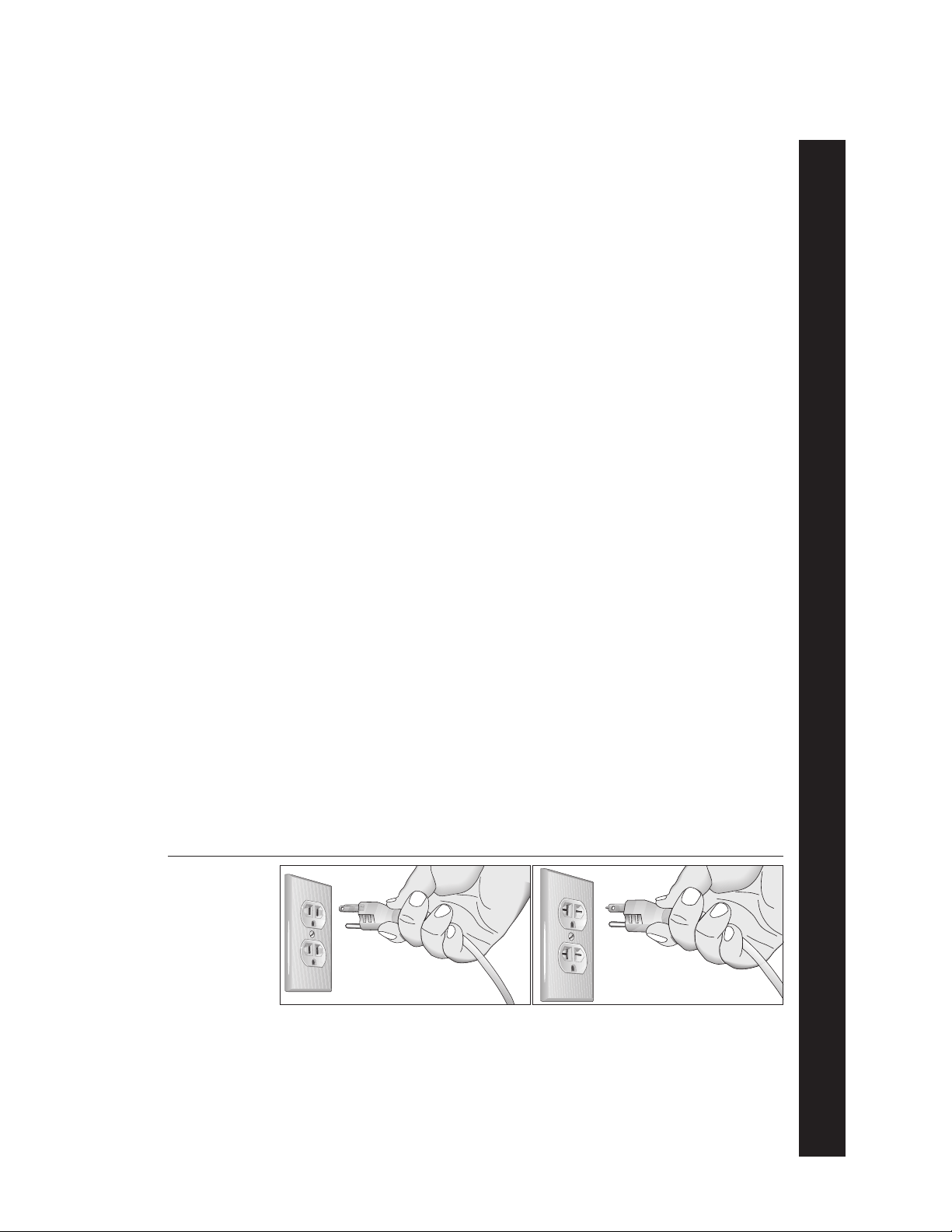
Diagram 1
Correct power
plug for U.S.
Markets:
120-volt and
240-volt.
120-volt grounding plug 240-volt grounding plug
IMPORTANT SAFETY INSTRUCTIONS
120V Units and 240V Units Designated for U.S. Markets
The C932 treadmill must be connected to a dedicated, grounded circuit.
circuit is recommended.
to permit connection to a proper electric circuit as shown in Diagram 1. The power outlet must
have the same configuration as the plug. No adapter should be used with this product.
The treadmill is factory-equipped with a specific power supply cord
SAVE THESE INSTRUCTIONS
A 20 amp dedicated
page 3
Page 4

COMMERCIAL PRODUCTS DIVISION
Table of Contents
Important Safety Instructions .........................................2
Safety Approval...................................................................... 3
Grounding Instructions........................................................... 3
Radio Frequency Interference (RFI)....................................... 6
European Applications ........................................................... 6
Obtaining Service .................................................................. 7
About this Manual .................................................................. 7
Unpacking the Treadmill .................................................. 8
Standard Equipment .............................................................. 8
Other Equipment.................................................................... 8
Hardware Kit .......................................................................... 9
Acquire Additional Tools ......................................................... 9
Setting Up the Treadmill.................................................10
Installation Requirements ...................................................... 10
Assembly Instructions ............................................................ 10
Turning the Unit ON and OFF ................................................ 18
Checking the Alignment of the Running Belt .......................... 19
Club Information.............................................................20
Programming Tips .................................................................. 21
Selecting the Language ......................................................... 22
Determining the Units of Measure ......................................... 22
Determining the Club Speed Limit ......................................... 23
Setting a Workout Time Limit ................................................. 23
Setting a Pause Time Limit .................................................... 23
Setting a Cool Down Time Limit ............................................. 24
Viewing the Odometer, Hours of Use,
Software Version, and Error Log ............................................ 24
The C932 Display............................................................26
Features on the Display Console ........................................... 26
Setup Mode and Prompts ...................................................... 27
The Setup Mode and the QUICKSTARTTM Feature ................ 28
Center Display During a Workout ........................................... 29
page 4
Page 5

COMMERCIAL PRODUCTS DIVISION
Table of Contents
The C932 Keypad ........................................................... 30
Keypad Tips ........................................................................... 30
Special Keypad Functions at the Precor Banner .................... 30
Keys on the Keypad ............................................................... 32
Changing the Display Features Using the SELECT Key ........ 34
Exercising on the C932 ..................................................35
Safety Features ..................................................................... 35
Using the Security Clip .......................................................... 35
Using the Handrails ............................................................... 35
Using the Stop Button ............................................................ 36
Reviewing Keypad and Workout Tips ..................................... 36
Quick Steps to Working Out ................................................... 37
Cooling Down After a Workout ............................................... 38
Pause, Workout Summary, and Exit Features ........................ 39
C932 Courses .................................................................40
Course Features .................................................................... 40
Course Descriptions .............................................................. 42
Heart Rate Capabilities ..................................................44
Using the SmartRate® Feature............................................... 44
Heart Rate Course ................................................................. 46
Maintenance....................................................................47
Inspection .............................................................................. 47
Cleaning the Equipment......................................................... 47
Aligning the Running Belt ....................................................... 47
Servicing the Treadmill ........................................................... 49
Storing the POLAR® Chest Strap ........................................... 49
Long Term Storage ................................................................ 49
Exploded Views ..................................................................... 50
Warranty Registration ............................................................ 57
Specifications ............................................................ back cover
page 5
Page 6

COMMERCIAL PRODUCTS DIVISION
RADIO FREQUENCY INTERFERENCE (RFI)
Federal Communications Commission Part 15
The treadmill has been tested and found to comply with:
• The IEC EMC Directive (international electromagnetic compatibility certification)
• The limits for a Class A digital device, pursuant to Part 15 of the FCC Rules.
These limits are designed to provide reasonable protection against harmful
interference in a commercial installation. The treadmill generates, uses, and
can radiate radio frequency energy and, if not installed and used in accordance with the owner’s manual instructions, may cause harmful interference
to radio communications. Operation of the treadmill in a residential area is
likely to cause harmful interference. If this occurs, the user will be required to
correct the interference at his or her own expense.
CAUTION —
Per the requirements of the Federal Communications
Commission, changes or modifications to this
product, not expressly approved by Precor, could
void the user’s authority to operate the product.
Canadian Department of Communications
This digital apparatus does not exceed the Class A limits for radio noise emissions
from digital apparatus set out in the Radio Interference Regulations of the Canadian
Department of Communications.
Le présent appareil numérique n’émet pas de bruits radioéélectriques dépassant
les limites applicables aux appareils numériques de la Class A prescrites dans le
Règlement sur le brouillage radioélectrique édicté par le ministére des Communications du Canada.
EUROPEAN APPLICATIONS
This product conforms to the requirements of the European Council Directive 89/336/
EEC,
Electromagnetic Compatibility
EN55022, Limits & Methods of Measurement of Radio Interference, Information Technology Equipment (Class A). Per the standard, the treadmill is a Class A product. In a
domestic environment, this product may cause radio interference, in which case the
user is responsible to take adequate measures to alleviate the interference.
EN50082-1, Generic Immunity Standard for Residential, Commercial and Light
Industrial Products (Class A).
This product additionally conforms to the requirements of the European Council Directive 73/23/EEC,
IEC 335-1, Safety of Household and similar Electrical Appliances.
Low Voltage Directive
and has been tested to the following standards:
and has been tested to the following standard:
page 6
Page 7

COMMERCIAL PRODUCTS DIVISION
OBTAINING SERVICE
Do not attempt to service the treadmill yourself except for the maintenance tasks
described in this manual. The treadmill does not contain any user-serviceable
parts. For information about product operation or service, visit the Precor Web
Site at www.precor.com or contact an authorized Precor Commercial Products
Customer Support Representative at 1-888-665-4404.
To help customer support personnel expedite your call, have your serial number
available. The serial number can be found on the shipping container or on the
label near the power receptacle. If you have any questions regarding the treadmill, use the model and serial numbers whenever you call a Precor dealer or
Commercial Products Customer Support Representative.
Model number: C932
Unit number: ________ Serial number: _____________________________
Unit number: ________ Serial number: _____________________________
Unit number: ________ Serial number: _____________________________
ABOUT THIS MANUAL
This manual includes instructions for installing and using the treadmill. To maximize the use of the treadmill, please study this manual thoroughly. The manual
uses the following conventions for identifying special information:
Note: Contains additional information.
Important: Indicates information to which you should pay special attention.
CAUTION: Indicates steps or information necessary to prevent harm to
yourself or damage to the equipment.
WARNING —
DANGER —
Provides instructions to prevent electrical damage to the equipment and injuries to yourself.
Indicates steps you must take to prevent electrical
shock.
page 7
Page 8
COMMERCIAL PRODUCTS DIVISION
Unpacking the Treadmill
Thank you for purchasing the Precor C932 treadmill. Built to the exacting standards of the health club environment, the treadmill is intended for commercial
use and can withstand the rigors of daily club use with little maintenance.
Important: Before using the treadmill, we urge you to familiarize yourself and
your staff with the entire Owner’s Manual. Understanding this manual will help
you and your customers use the treadmill safely and successfully.
Your treadmill is carefully inspected before shipment so it should arrive in good
operating condition. Precor ships the unit in the following pieces:
❑ Running bed assembly
❑ Right and left upright supports
❑ Display console
❑ Right and left center handrails (two sections) – found inside the cardboard
packing material
❑ Right and left center handrail side covers – packaged inside a plastic bag
❑ Power cord – packaged inside a plastic bag in the shipping container
❑ Hardware kit – shrink wrapped to cardboard
❑ Owner’s Manual– packaged inside a plastic bag in the shipping container
CAUTION: This unit weighs over 280 pounds (126 kilograms). To prevent
injury to yourself or damage to the equipment, obtain appropriate assistance before removing the unit from the pallet.
If any items are missing, refer to
STANDARD EQUIPMENT
The treadmill incorporates the Precor SmartRate® and Heart Rate features into
its display console.
the cardboard packing material
shaped like this to find the
center handrails.
Obtaining Service
Look inside
on page 7.
Note: An optional POLAR® chest strap must be worn to transmit a user’s heart
rate to the display console.
OTHER EQUIPMENT
Optional equipment available through your dealer includes:
• POLAR® chest strap
• Side handrails
If you are interested in obtaining Precor option kits for your unit, check with your
dealer. For customer support, see
page 8
Obtaining Service
on page 7.
Page 9
COMMERCIAL PRODUCTS DIVISION
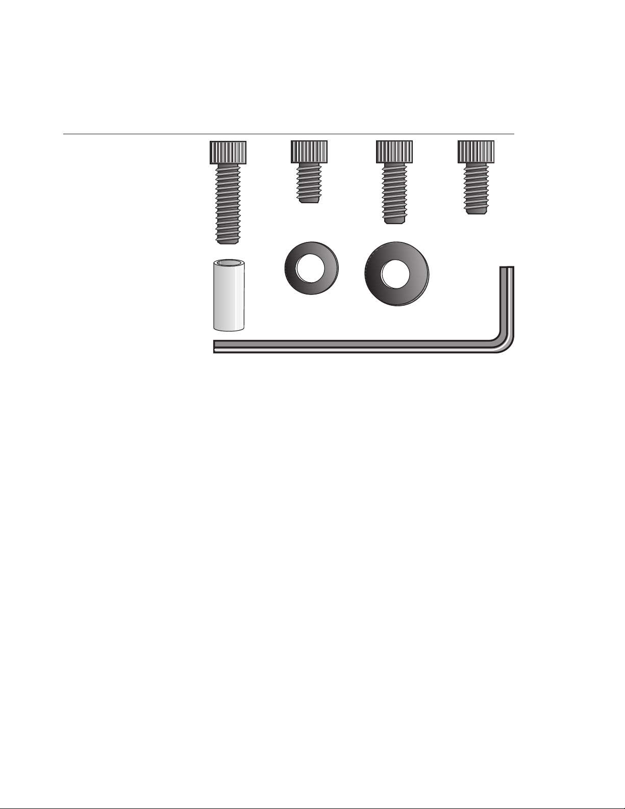
Diagram 2
Hardware kit.
Carefully unpack the pieces of the treadmill and lay them on the floor near
the location where you plan to use the treadmill.
HARDWARE KIT
After unpacking the treadmill, open the hardware kit (refer to Diagram 2) and
make sure that you have the following items:
AC
B
D
F
E
G
H
❑ (A) four 2-inch long socket head screws — mount upright supports to base
❑ (B) four barrel spacers — place on 2-inch screws
❑ (C) ten ¾-inch long socket head screws
❑ (D) sixteen flat washers
❑ (E) two 1½-inch socket head screws — handrail clamp assembly
❑ (F) four large diameter washers — place on handrail end cap screws
❑ (G) four 1-inch socket head screws — handrail mounting bracket
❑ (H) ¼-inch hex key — 3 inches by 10 inches
If any items are missing, refer to
Note: After assembling the treadmill, you will have four ¾-inch long socket head
screws (C) and four flat washers (D) remaining. You can discard them if you wish.
Also, be sure to store the hex key in a secure place. It is used for specific maintenance procedures that are described in this manual.
ACQUIRE ADDITIONAL TOOLS
Obtain the following tools
❑ Wire cutter ❑ Bubble level
❑ ½-inch box end wrench ❑ Medium weight string
(or crescent wrench)
before
Obtaining Service
on page 7.
assembling the treadmill.
page 9
Page 10
COMMERCIAL PRODUCTS DIVISION
Setting Up the Treadmill
You do not need any special knowledge or experience to set up the treadmill.
However, you will need assistance during assembly.
INSTALLATION REQUIREMENTS
Follow these installation requirements when installing the treadmill.
install the treadmill according to the following guidelines, you could void the Precor
limited warranty.
• Set up the treadmill on a solid, flat surface. Unpack and assemble the
treadmill close to where you plan to use it. Make sure that the surface under
the unit is smooth and level. A level unit is required for the user’s safety and
proper operation.
• Provide ample space around the unit. Open space around the unit makes
for a safer mount and dismount.
• Fill out and mail the limited warranty card. The serial number can be found
on the shipping container or on the label near the power receptacle. Write the
serial number onto the Precor limited warranty card found inside the back
cover of this manual and in the
• Use the appropriate voltage, dedicated circuit, and grounding as speci-
fied on the treadmill. A 20 amp dedicated circuit is recommended.
ASSEMBLY INSTRUCTIONS
To assemble the treadmill, take the following steps.
1. Obtain adult assistance. Have your assistants help place the shipping carton
close to the location where you plan to use the treadmill. Break down the side
walls of the shipping carton so that they lie flat. Remove the loose contents.
Obtaining Service
If you do not
section on page 7.
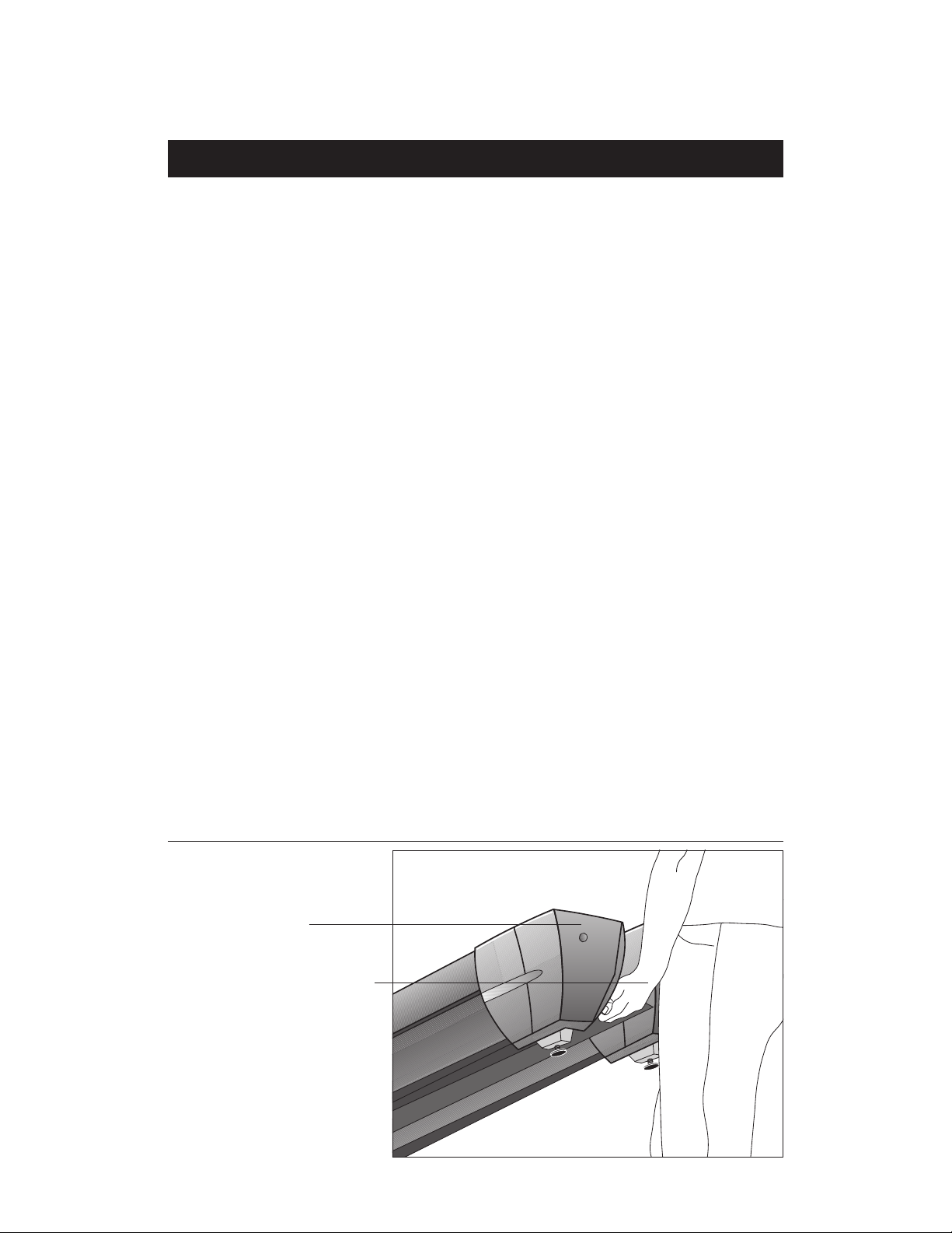
Diagram 3
page 10
2. Make sure that the power switch is OFF. Check the ON/OFF power switch
on the front of the treadmill. Place the switch in the O (OFF) position. Make
sure that the treadmill is not plugged into a power source.
Lift the rear of the
unit and roll it to its
assembly location.
End cap
Lift rear by placing
hands on opposite
sides of the cross
brace that is found
under the rear cover.
Page 11
COMMERCIAL PRODUCTS DIVISION
CAUTION: Do not lift the rear end of the treadmill by grasping the rear
roller or the end cap. The running belt can move and the end caps can
break off which may cause injury to you or to the unit.
3. Move the treadmill. Diagram 3. To avoid injury to yourself or damage to the unit,
ask for help in placing the treadmill where you plan to use it. Diagram 3 illustrates
how to properly lift the rear end so that you can roll it on its front wheels.
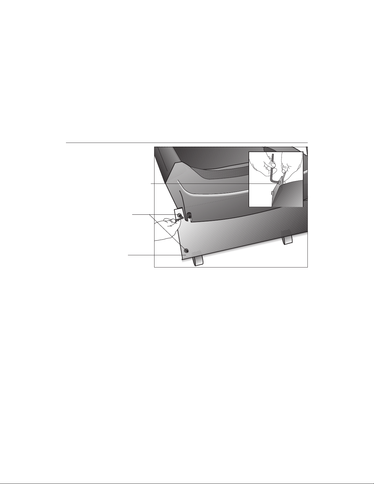
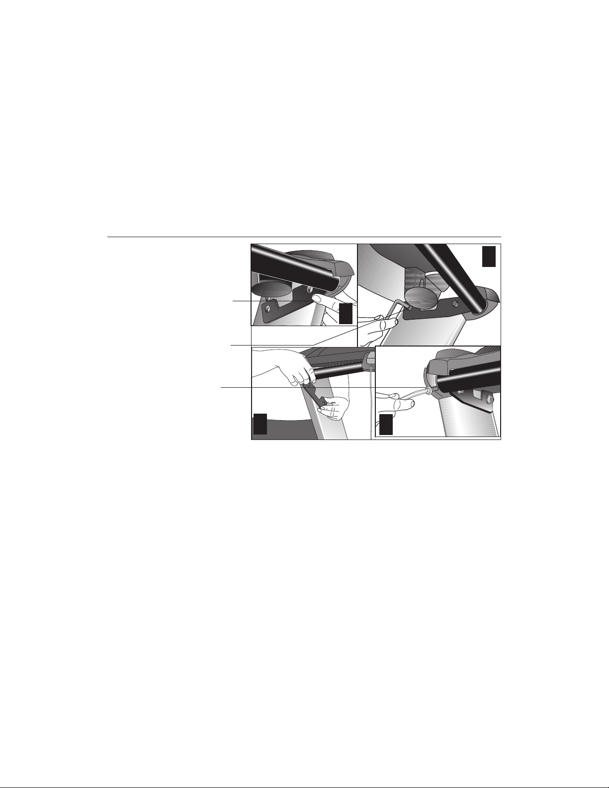
Diagram 4
Remove the shipping
fasteners from the
front panel.
Loosen the fasteners
with a hex key while
holding the nut with
a crescent or box
end wrench.
The shipping
fasteners are found
on the right and left
sides of the front
panel.
Front panel
4. Remove the shipping fasteners from the front panel. Diagram 4. With
the supplied hex key and a ½-inch box end wrench, loosen and remove the
4 bolts, washers and nuts on the front panel. These fasteners are used
during shipping to hold the front plate in place. Discard the fasteners.
5. Remove any tape or wire ties securing the display cable to the side of
the unit.
page 11
Page 12
COMMERCIAL PRODUCTS DIVISION
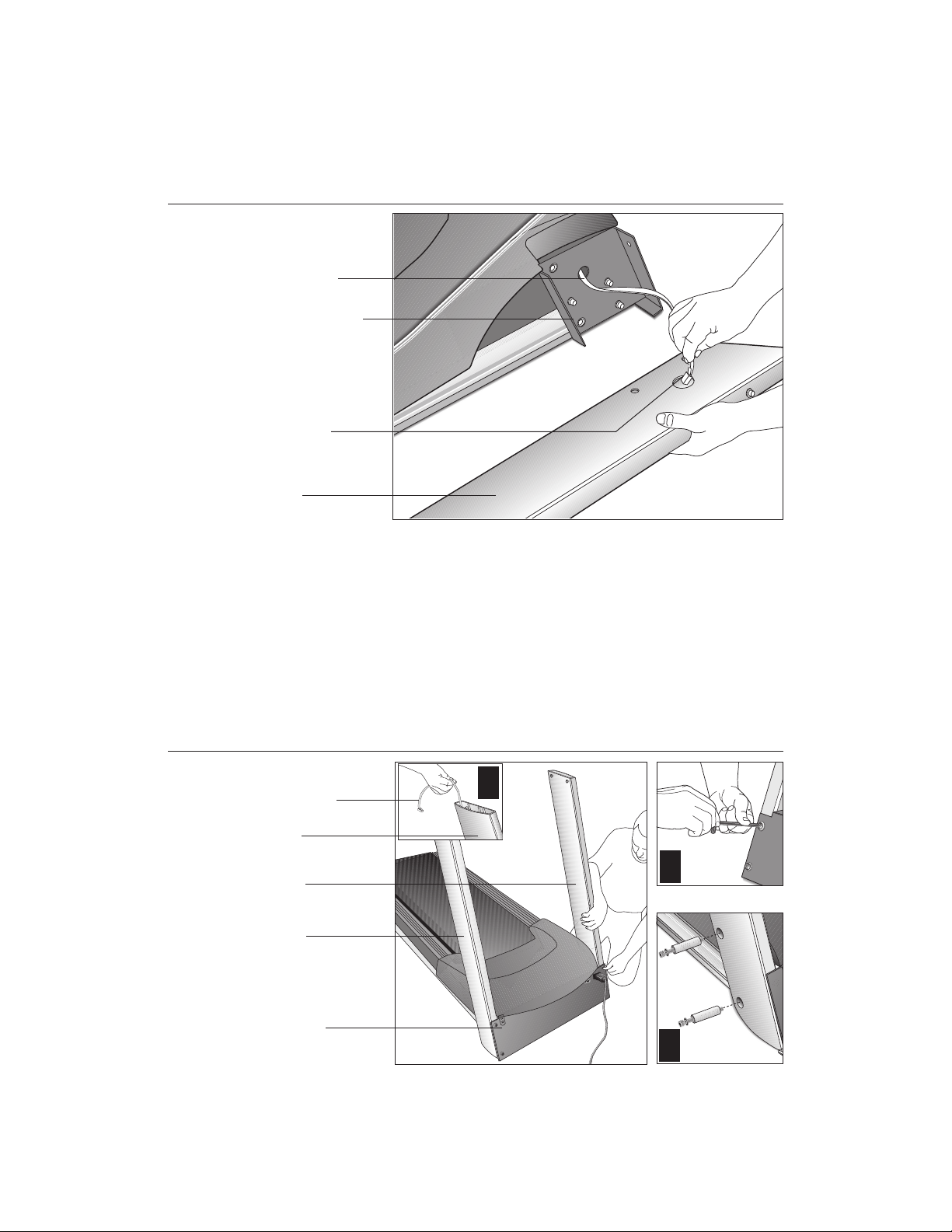
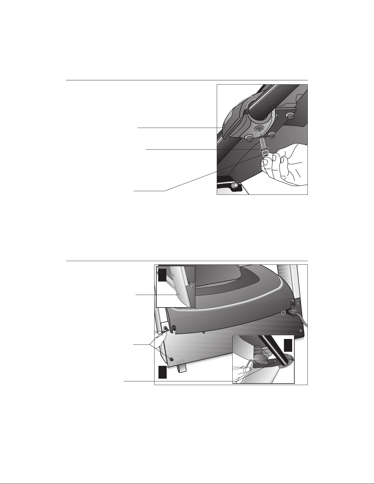
Diagram 5
Route the cable.
Display cable
Right side
mounting bracket
Route cable
through hole.
Right side upright
support
CAUTION: To avoid damage to the display cable, read and follow these
steps carefully. Damage to the cable due to improper assembly is not
covered by the Precor limited warranty.
6. Route the display cable. Diagram 5. Unwrap the cable and remove any
kinks. Have an assistant hold the right upright support close to the base
while you route the cable through it.
Diagram 6
Note: Attaching a string to the cable with a washer tied to the opposite end
of the string may help you route the cable through the upright support.
Attach the upright
supports.
Display cable
Right side upright
support
Left side upright
support
Right side upright
support
Attach the right
side support first.
Front panel
1
2
3
7. Attach the
Align the right side upright support with the base assembly mounting locations while your assistant keeps tension on the cable. Refer to Diagram 6, #1.
To secure the upright support to the base assembly, take the following steps:
right side
upright support to the base assembly. Diagram 6.
page 12
Page 13
COMMERCIAL PRODUCTS DIVISION
a. Place a washer (D) onto each of two ¾-inch screws (C). Thread the screws
through the front panel and into the upright support. See Diagram 6, #2.
Do not fully tighten the screws. Leave room for final adjustments.
CAUTION: Avoid pinching the cable with the bolts and spacers.
b. Place a washer (D) and barrel spacer (B) on each of two 2-inch screws
(A). Insert the screws through the upright support and thread them into
the base mounts. See Diagram 6, #3. Do not securely tighten the screws
until after the unit has been fully assembled.
Diagram 7
8. Attach the
left side
upright support to the base assembly. Diagram 6.
Align the upright support with the base assembly mounting bracket and
secure it by following steps 7a. and 7b.
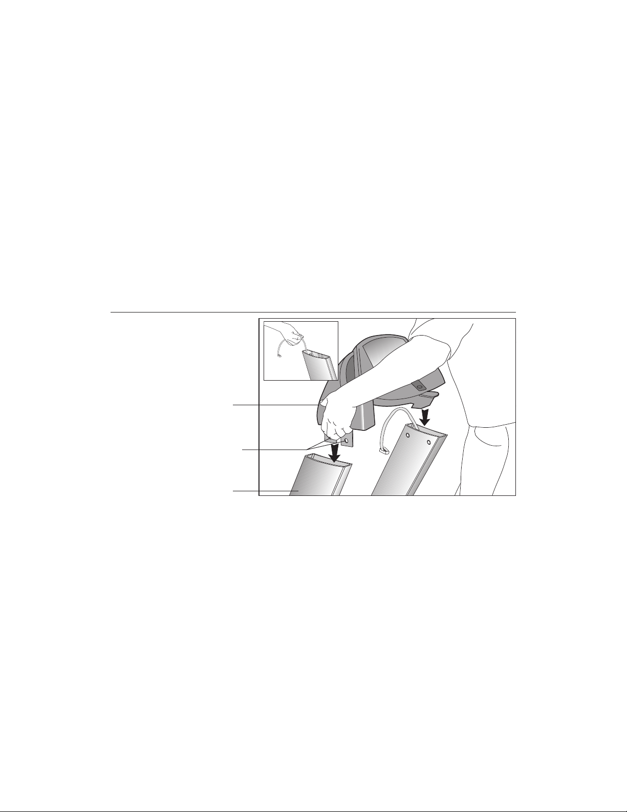
Install the display
console.
Display console
Display console
mounting brackets
Upright support
9. Position the display console onto the upright supports. Diagram 7. Make
sure that the cable is routed through the top of the upright support. Have an
assistant hold onto the cable (see inset) and then, rest the display console
on the upright supports and align the mounting holes.
CAUTION: Do not crimp or pinch the cable! Crimped or pinched cables
are not covered by the Precor limited warranty.
page 13
Page 14
COMMERCIAL PRODUCTS DIVISION
Diagram 8
Connect the cable.
1
Cable connector
Cable receptacle
Display console
Mounting holes
Tie wrap
Upright support
Cable connector
4
2
3
10. Connect the display cable and secure the display console. Refer to
Diagram 8, #1 and take the following steps to secure the display cable and
console.
a. Attach the cable connector by sliding it into its receptacle underneath the
console. A definite “click” is heard when the cable is properly attached.
Refer to Diagram 8, #2. If you do not hear and feel the connector “snap”
into place, reinsert it.
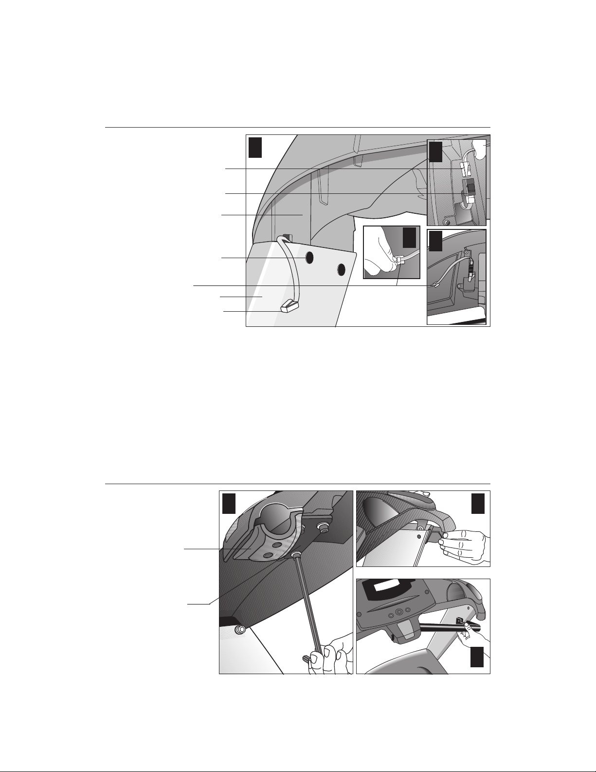
Diagram 9
b. So that the cable does not hang below the console, slide it into the two tie
wrap clips found underneath the console. Refer to Diagram 8, #3 and #4.
Install the
center
handrail.
Handrail
clamp
Handrail
clamp
bracket
1 2
3
page 14
Page 15
COMMERCIAL PRODUCTS DIVISION
11. Install the center handrail. Loosen the four fasteners in the handrail clamp
bracket with the hex key provided. See Diagram 9, #1. The center handrail is
packaged in two pieces. Install one side at a time by following these steps:
a. Insert a handrail end cap. See Diagram 9, #2.
b. Slide the end of the handrail into the center clamp and rotate the handrail
so that it falls inside the end cap. See Diagram 9, #3.
Diagram 10
Secure the display
console and center
handrail.
Center handrail
mounting bracket
(right side)
1
1-inch screws (G)
with washers (D)
(right side)
Handrail end cap
screw (C) with
washer (F)
(left side)
3
4
c. Align the center handrail’s mounting bracket with the holes in the upright
support. See Diagram 10, #1. Insert two 1-inch screws (G) with washers
(D) and finger tighten. See Diagram 10, #2. Do not securely tighten the
screws until both sides of the center handrail have been attached. See
Diagram 10, #1 and #2.
d. Align the mounting holes in the handrail with the end cap. Place a washer (F)
on screw (C) and insert the screw. Finger tighten. See Diagram 10, #4.
2
e. Follow steps 9a. through 9d. on the opposite side.
page 15
Page 16
COMMERCIAL PRODUCTS DIVISION
Diagram 11
Secure the upper handrail clamp.
Handrail clamp
Washer (F) with
1½-inch screw (E)
Tighten the screws,
but leave room for
adjustments.
12. Install fasteners in the handrail clamp. Diagram 11. Return to the center
handrail clamp and place a large washer (F) onto each of two screws (E).
Thread the screws through the handrail clamp. Finger tighten.
CAUTION: Do not overtighten the screws or you may inadvertently
cause stress cracks.
Diagram 12
Secure the fasteners.
2
Second: Alternately
tighten four side
upright screws.
First: Alternately
tighten four front
panel screws.
Third: Alternately
tighten the four
screws that secure
the console to the
uprights.
1
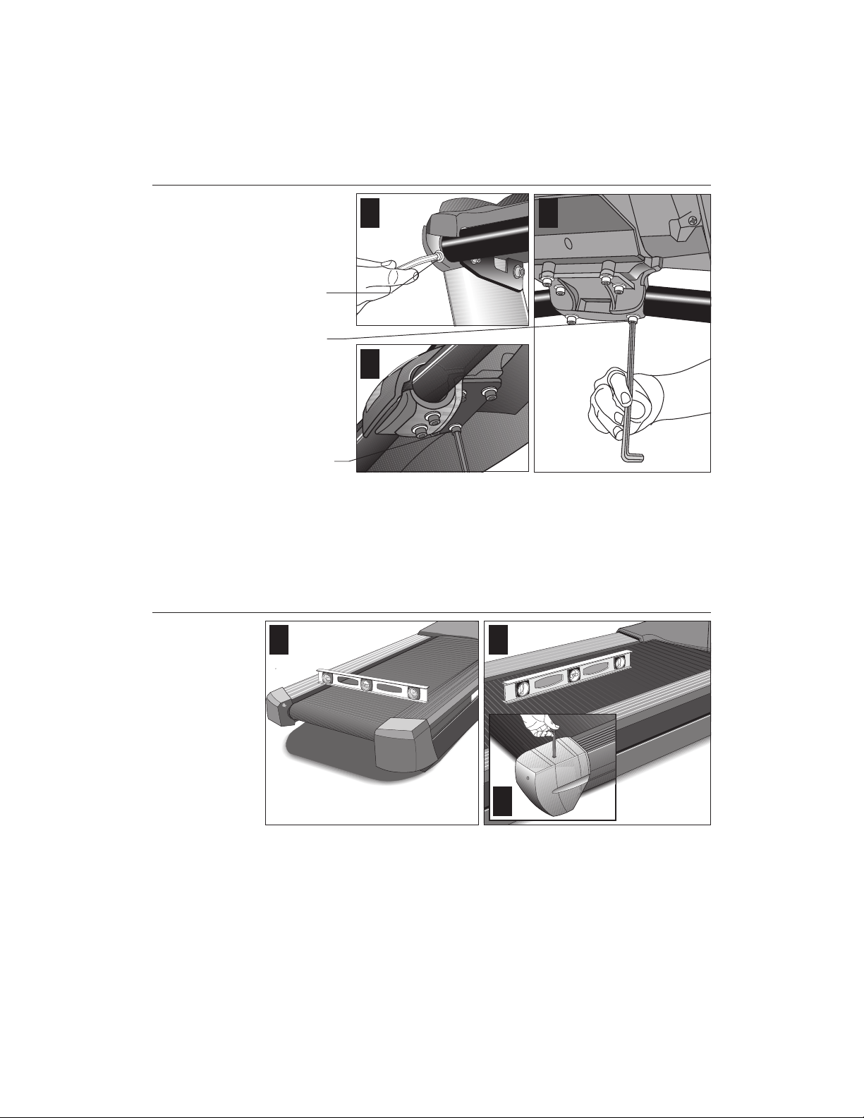
13. Tighten all mounting screws with the hex key (H) provided. Diagram 12.
Start at the front of the treadmill with the four screws that attach the upright
supports to the front panel. Tightening these screws first helps pull the rest
of the treadmill’s parts into alignment. Then, proceed with tightening the four
screws (A) that secure the upright supports and the four display console
assembly screws (C).
3
page 16
Important: For proper alignment, it is critical that the fasteners are
tightened in the order shown in Diagrams 12 and 13.
Page 17
COMMERCIAL PRODUCTS DIVISION
Diagram 13
Tighten the handrail
fasteners.
Handrail end cap
Center handrail
clamp screws (2)
1
2
3
Center console
bracket screws (4)
14. Tighten all the center handrail fasteners. Diagram 13. Start with tightening
the two end cap screws and work inward. See Diagram 13, #1. So that you
don’t overtighten the fasteners, hold the supplied hex key by its 3-inch section
and tighten the two center clamp screws. Refer to Diagram 13, #2. Next,
tighten the four console bracket screws. Refer to Diagram 13, #3.
Diagram 14
Level the unit.
1
2
3
15. Level the unit. Diagram 14. The C932 has adjustable rear feet. Check to make
sure that the running surface is level (use a bubble level as shown in Diagram
14). If the treadmill is placed on a slightly, uneven surface, adjusting the rear
feet can help, but will not compensate for extremely uneven surfaces.
Important: If you need to make adjustments, adjust one rear foot at a time.
Do not use the rear foot to raise or lower the unit more than ¾-inches.
Check the level of the unit after each adjustment.
16. Adjust the rear deck. Diagram 14, #3. To raise the rear deck, insert the
¼-inch hex key (G). Make sure that the key is fully engaged and turn it
clockwise. Turning the hex key counterclockwise lowers the unit.
page 17
Page 18
COMMERCIAL PRODUCTS DIVISION
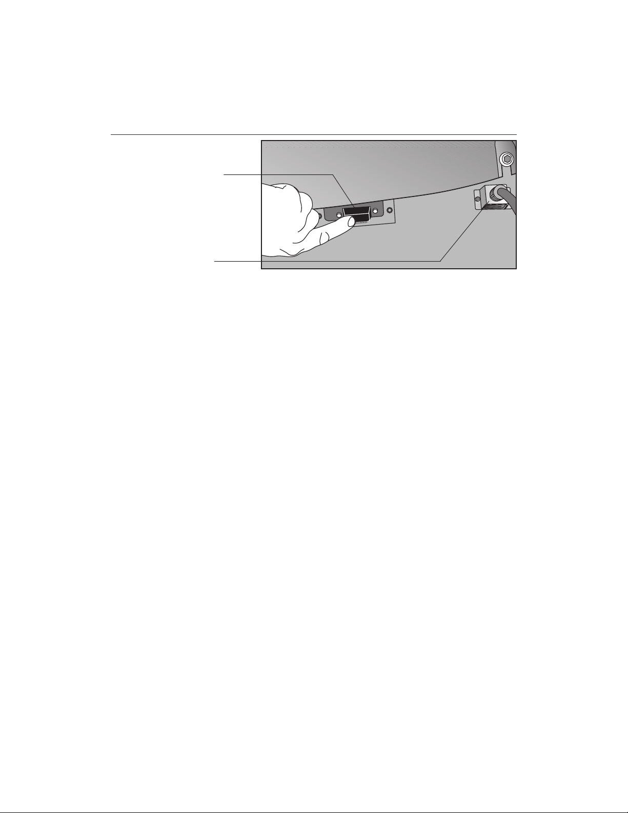
Diagram 15
Connect to power
outlet.
On/Off switch
Power plug
17. Plug the power cord into an appropriate power outlet. Refer to
ing Instructions
on page 3. Make sure that the ON/OFF (I/O) power switch,
located on the front panel of the treadmill, is placed in the OFF (O) position.
CAUTION: The treadmill requires a dedicated, grounded circuit.
A 20 amp circuit is recommended. Make sure that no other product or
machine uses the same circuit as the treadmill.
Important: Always make inspecting the power cord connection part of your
routine treadmill maintenance.
TURNING THE UNIT ON AND OFF
2
Ground-
Use the ON/OFF (I/O) power switch to turn the unit ON and OFF. This switch is
located on the front of the unit, near the power plug receptacle.
To complete the installation of the treadmill, continue to
of the Running Belt
on the next page
.
Checking the Alignment
page 18
Page 19

COMMERCIAL PRODUCTS DIVISION
CHECKING THE ALIGNMENT OF THE RUNNING BELT
The belt is aligned at the factory before shipment. However, during shipment or by
using the treadmill on an uneven surface, the belt might move off center. Proper
belt alignment is important because it allows the belt to remain centered and
assures smooth operation.
Follow these steps to check the alignment:
CAUTION: Do not walk on the running belt during this procedure.
1. The treadmill has adjustable rear feet. Check to make sure that the running
surface is level (refer to steps 15 and 16 on the previous pages). If the
treadmill is placed on a slightly uneven surface, adjusting the rear feet can
help, but will not compensate for extremely uneven surfaces.
2. Locate the I/O switch at the front of the treadmill and turn the unit ON.
3. Stand beside the treadmill and press QuickStart. The running belt starts
automatically after the message, “
CAUTION: If you hear any chafing or the running belt appears to be
getting damaged, stop the running belt immediately by pressing the
STOP key. Contact Customer Support.
Belt Starting 3, 2, 1,...
” appears.
4. Continue standing next to the treadmill and hold down the SPEED
▲ key
until the display shows a speed of 3 miles per hour (5 kph).
5. Walk around to the rear of the unit and observe the belt for a few minutes as
it moves.
If the running belt,... Then,...
tracks centered on the running surface the belt is functioning correctly
(evenly distributed between the side rails) and no adjustment is necessary.
runs or drifts off center you need to adjust the belt; see
Aligning the Running Belt,
page 47.
Important: If you notice that the belt needs alignment, make the adjustments at
once. Failure to do so might cause the belt to tear or fray, which is not covered by
the Precor, limited warranty.
6. To stop the running belt, press the red Stop button.
If the belt is functioning correctly, the C932 treadmill is ready to use.
page 19
Page 20

COMMERCIAL PRODUCTS DIVISION
Club Information
These next few pages provide information that lets you customize the treadmill for
your Club. It is not information that your customer needs or, necessarily, should see.
Information that you can access and features that can be customized are as follows:
Custom Feature Factory Setting What you are allowed to change
Language English Choose one of six languages: English,
German, Spanish, French, Dutch, or
Portuguese.
Units of Measure U.S. Standard Select between U.S. Standard and
Metric displays.
Maximum Speed 0.5 to 11.0 mph Determine the maximum speed that
a user can select. Selections range
between 0.5 to 11 mph (1 to 18 kph).
Maximum Workout Time 60 minutes Set a maximum limit on workout time.
Note: Remember that the user can get
up to an additional five-minute cool
down period appended to a completed
course. So, adjust the maximum time
limit accordingly.
Maximum Pause Time 120 seconds Set the maximum duration in which a
user can “pause” his or her workout.
Max. Cool Down Time 5 minutes Set the maximum duration in which a
person can cool down after a workout.
Odometer, Hours of Use Zero Display only (no changes allowed).
Software Version Current version Displays the upper and lower software
version number which is valuable
when calling Customer Support.
Error Log NO ERRORS The treadmill stores the cumulative
miles or kilometers, the number of
hours that the unit has been in use,
the software version and software
type (which is valuable when calling
Customer Support), and an error log
(useful when troubleshooting).
page 20
Note: If your customers are interested in the learning more about the C932 treadmill,
you may wish to direct them to the manual available on the web site (www.precor.com).
(The manual, which appears on the web site, does not contain the information found
in this section.)
Page 21

COMMERCIAL PRODUCTS DIVISION
Diagram 16
C932 display and
keypad.
Center display
PRECOR
scrolling banner
appears here.
SELECT key
RESET key
Keypad keys
C932
PROGRAMMING TIPS
Certain aspects of the C932 are hidden and can only be accessed using special key
presses. To avoid unauthorized use, certain rules apply. See Diagram 16. Tips to
consider while programming or viewing diagnostic information are shown below:
• Always start at the scrolling PRECOR banner.
• The advanced programming and diagnostic mode is accessed by pressing the
RESET key (or the red STOP button) while the PRECOR banner is displayed.
A second key press must occur within 1/2 second after pressing RESET (or the
red STOP button) or the display returns to the PRECOR banner. The third and
subsequent key presses must occur within four seconds of the previous key
press or the PRECOR banner returns and you will need to begin again.
Display key functions within the Club Custom Mode
▼▲ lets you scroll through the
various selections that appear.
The longer the key is held down,
the faster the numbers scroll past.
Stop advances to the next aspect of the
program without storing the information that appears on the display.
RESET exits Club Custom mode and
displays the PRECOR banner.
SELECT saves the information being
displayed and moves to the
next aspect of the program.
QUICKSTART disabled.
• Exit the programming or diagnostic mode by pressing RESET. Note that
the display remains blank for one second and any additional key presses are
ignored during that second.
page 21
Page 22

COMMERCIAL PRODUCTS DIVISION
SELECTING THE LANGUAGE
Display prompts can appear in English, German, Spanish, French, Dutch, or
Portuguese. Use the ▼▲ keys to display your preference and press SELECT.
DETERMINING THE UNITS OF MEASURE
The C932 can display units of measure in either U.S. Standard (miles, miles per
hour) or Metric (kilometers, kilometers per hour). When the treadmill is shipped
from the factory it is set to display U.S. Standard units of measure. You can easily
change this setting by taking the following steps:
1. Check that the C932 is ON. If necessary, turn ON the treadmill using the
power switch located at the front of the unit.
2. At the scrolling PRECOR banner, press the following keys in sequence:
RESET, SELECT, SPEED ▼, SELECT, INCLINE ▲, SELECT, SPEED ▼, SELECT
Numbers appear associated with the key that you pressed: 5,6,5,1,5,6,5
Important: If the second key (SELECT) is not pressed within 1/2 second
after RESET, the display returns to the PRECOR banner and you need to
begin again.
3. The prompt, SELECT UNITS scrolls across the display and then, the current
unit of measure appears. The message scrolls continually until you press a
key. Any ▼ or ▲ key lets you alternate between the prompts.
4. Once your selection is displayed, three options exist. You can,
a. press the SELECT to accept the unit of measure being displayed and
continue with programming the treadmill. (Refer to
Speed Limit
.) The changes are saved in memory. The C932 will retain
Determining the Club
your selection even when it is turned OFF and unplugged.
b. press the red Stop button, which keeps the “current unit of measure”,
unchanged and advances to the next section.
Note: The “current unit of measure” is not necessarily the one being displayed. It refers to the unit of measure that was in existence prior to
entering the SELECT UNITS program.
c. press RESET, which keeps the “current unit of measure”, unchanged,
ends programming mode, and returns to the PRECOR banner.
Important: If you change the Unit of Measure display, be sure to check the
speed limit setting to verify that it is correct. Refer to Determining the Club
Speed Limit below.
page 22
Page 23

COMMERCIAL PRODUCTS DIVISION
DETERMINING THE CLUB SPEED LIMIT
You can set a maximum speed for the treadmill. This limits how fast the running
belt moves and, consequently, how many adjustments a user can make to the
treadmill’s speed. The speed is displayed in miles per hour (mph) or kilometers
per hour (kph) depending upon the units of measure (U.S. standard or Metric)
that are selected. Once the prompt SET MAX SPEED scrolls across the display,
use the ▼▲ keys to choose a speed between: 0.5 to 11.0 mph (1.0 to 18 kph).
Press SELECT to continue programming the treadmill. Refer to step 4 above.
Important: If you select a number that limits the miles per hour, your change will
not affect the kilometers per hour (and vice versa). The treadmill does not convert the speed entered in miles per hour (U.S. standard) to kilometers per hour
(Metric). It stores separate numbers for the different units of measure.
SETTING A WORKOUT TIME LIMIT
You can limit how long a user works out by setting a duration between 1 and 99
minutes. The treadmill also lets you choose NO LIMIT (found at the zero point between 99 and 1) which allows the user to select a course and work out indefinitely.
Note: The QuickStart program is automatically limited to the Club limit. For example, if you set the workout time limit to 20 minutes, the treadmill allows users
to specify a workout between 1 and 20 minutes. Users cannot specify a time
longer than 20 minutes.
Important: An exception to the rule is the Weight Loss course. It has a course
duration of 28 minutes.
Use the ▼▲ keys to select a workout time limit. Touch either ▼▲ key and the
display changes in one minute increments. Press and hold the ▼ or ▲ key and
the numbers advance or decrease faster. Take into account that the user may
get an additional cool-down period appended to his or her workout (depending
on course selection), so adjust the maximum time limit accordingly.
Press SELECT to continue programming the treadmill. Refer to step 4 above.
Note: If the workout time is set to NO LIMIT users can workout indefinitely and no
cool-down is appended to the course. The exception is the Weight Loss course.
SETTING A PAUSE TIME LIMIT
Setting a pause time limit is useful because the treadmill returns to the PRECOR
banner at a selected interval after the Stop key is pressed.
After the reading the scrolling prompt and message, use the ts keys to set the
pause time limit between 1 and 120 seconds (two minutes).
Press SELECT to continue programming the treadmill. For other options, refer to
step 4 on the previous page.
page 23
Page 24

COMMERCIAL PRODUCTS DIVISION
SETTING A COOL DOWN TIME LIMIT
You can set a limit to the duration of a user’s cool down time in one-minute increments. It is highly recommended, in most workout literature, that a user cool down for
at least three minutes to allow their heart rate to return to a “normal,” non-exercising
state. A cool down period also allows lactic acid, which may have built up in a person’s
body during a workout, to dissipate somewhat during the cool down phase.
After the scrolling prompt appears, use the ts keys to set a cool down time limit
between 1 and 5 minutes.
Press SELECT to accept the displayed value and return to the PRECOR banner.
For other options, refer to step 4 on the previous page.
VIEWING THE ODOMETER, HOURS OF USE, SOFTWARE
VERSION, AND ERROR LOG
Important: Review Programming Tips on the previous page before taking the
following steps.
To view the odometer, the number of hours that the running belt has been in use,
the C932 software version number, or the error log, begin at the PRECOR banner
and press the following key sequence:
RESET, SPEED ▼, SELECT
The numbers 6, 5 appear on the display as you press the associated key.
The field name MILES or KILOMETERS scrolls across the display and indicates
the unit of measure currently in use by the treadmill. The odometer value appears next. The odometer tracks the running belt movement. The numeric value
that appears indicates the distance traveled in cumulative miles or kilometers.
The message continues to scroll until you press a key. Refer to
Tips
on page 21.
Press the SELECT key and the word HOURS scrolls across the display. The
number that follows indicates the hours of that the running belt has been in use.
The C932 actually notes the passing of course minutes, but the numeric value
that appears is truncated to the nearest full hour.
Press SELECT again and the unit’s three digit software version number (upper
display software version) scrolls past followed by the lower board’s software version number. The words “UPPER SW:” and “LOWER SW:” appear prior to the
version being displayed.
Programming
page 24
Page 25

COMMERCIAL PRODUCTS DIVISION
Press SELECT once again and the Error Log appears. The most recent error log
appears first and scrolls across the display. If the words, NO ERRORS appear, no
errors have been recorded.
Up to ten error codes can be recorded and viewed in the following format.
The number of hours that the treadmill has been
Most recent error
in use when the error occurred
1: ER33 AT 12,345,678 MILES 1,714 HOURS
Error code
Odometer reading at the time the error occurred
Note: To clear (delete) the error log, press the QuickStart key for at least four
seconds while the message HOLD QUICKSTART TO CLEAR ERROR LOG scrolls
across the display. If the QuickStart key is released before the message finishes
scrolling, then the display returns to the previous error code. If you continue to press
the QuickStart key until the message finishes scrolling, then prompts appear on the
display and let you know when the error messages have been deleted from memory.
Important: You cannot retrieve the error log once you have deleted it.
To return to the PRECOR banner, press RESET, SELECT, or the red Stop button.
page 25
Page 26

COMMERCIAL PRODUCTS DIVISION
The C932 Display
The C932 is designed so users can work out with minimal instruction or training.
The directions on the console and the prompts on the display will guide a user
through the entire workout session. Before the treadmill is used, however, we
recommend that you, as club owner or manager, familiarize yourself with it so
you can instruct your customers to use it safely and effectively.
This section covers the following information:
• an overview of the different features provided on the display console
• an explanation about the Setup Mode and Display Prompts
• instructions for using the heart rate options
FEATURES ON THE DISPLAY CONSOLE
As a user works out, the display consecutively scans through the highlighted
features [PROFILE, TIME, DISTANCE, CALORIES, SPEED, INCLINE, HEART
RATE (HR) and SmartRate®]. Indicator lights appear next to the feature being
displayed. A user can change which features appear by pressing the SELECT
key. Refer to
Changing the Display Features Using the SELECT Key
on page 34.
Diagram 17 shows the display console label. Its display features and keys are
explained on the following pages.
Diagram 17
C932 display console
SmartRate® display
Course profile and
data entry fields
Once you begin a
course, the profile
appears in this portion of
the display and remains
until the scanning
process begins.
Keypad keys
The keys on the keypad let you:
• control your workout session,
• answer prompts prior to starting a course,
• determine which display features appear,
• prematurely end a course, and
• adjust the incline and speed.
Refer to Keys on the Keypad on page 32.
C932
Select key
Customize the display by highlighting an
LED indicator. Make your selections by
pressing the SELECT key. A lit LED
indicates which feature is being displayed.
page 26
Page 27

COMMERCIAL PRODUCTS DIVISION
The SmartRate® and Heart Rate system is standard equipment. The heart rate
receiver is factory-installed in the display console. To actively view the SmartRate
and heart rate displays, a user must wear a POLAR® chest strap, face the display console, enter his or her age (during the Setup prompts), and begin a course.
The user’s heart rate is transmitted from the chest strap to the receiver inside the
console and appears on the display. A blinking segment approximates the user’s
heart rate and shows which zone the heart rate is in: weight loss or cardiovascular.
Important: During a course, a user’s heart rate must be above 40 beats per
minute before the segment begins to blink. Note that pressing QuickStart at the
PRECOR banner causes the SmartRate® display feature to be inactive.
SETUP MODE AND PROMPTS
The PRECOR banner is the “starting point” when a user begins a workout. If the
banner does not scroll across the display, press the RESET key. If the display
appears blank, make sure that the treadmill is turned ON. Press the ON/OFF [I/O]
switch located at the front, near the power receptacle, to ON.
PRECOR banner: From the PRECOR banner, a user presses the SELECT key
to access the Setup mode which lets a user determine the course, workout time,
weight, and age parameters as described below.
Note: Key presses to the INCLINE ▼▲ or SPEED ▼▲ keys are ignored when the
banner is being displayed. Refer to page 30 for more information about the keypad.
®
MANL: The course prompt, MANL, indicates that the C932 is ready to accept
course entries. To help a user determine which course they want to use, the
course names and profiles appear on the display console label. The ▼ and ▲
keys let a user scroll through the available courses. The display presents the
abbreviated name of the course. To choose the selection being displayed and
continue in Setup mode, press SELECT. (Refer to
QuickStart Feature
on page 28.)
The Setup Mode and the
Note: Depending on the course that is selected, a user may be prompted for
other information. Refer to
C932 Courses
on page 40.
XX MIN: Acceptable entries at the workout time prompt range between NOLIM (zero)
and 99 minutes. Use the ▼ and ▲ keys to change the selection. If the club allows it
and a user wants to work out indefinitely, they can choose NOLIM. A cool-down
period will not be appended to the course. Note that the Weight Loss course has a
preset time limit so a user will not be prompted for a workout time when they choose
WTLS. A user cannot workout indefinitely in the Weight Loss course.
To continue in Setup mode, press SELECT.
Important: The club has the option to set limits on course duration and cool down
and pause time. Refer to Club Information on page 20.
page 27
Page 28

COMMERCIAL PRODUCTS DIVISION
150 LB (68 KG): Acceptable weight entries range from 1 through 999 (pounds or
kilograms). Change the number using the ▼ and ▲ keys or accept the displayed
number (and continue in Setup mode) by pressing SELECT.
Important: Enter a number that reflects a user’s actual weight since the calorie
count and several other calculations are based on the weight entry.
AGE 0: The age prompt appears if the heart rate receiver is properly installed in the
display console. Acceptable entries range from 1 to 99. Change the blinking number
using the ▼ and ▲ keys or accept the displayed number by pressing SELECT.
Important: An age entry is required if the user wants to use the heart rate capabilities of the treadmill. Refer to Heart Rate Capabilities on page 44.
TMTM
TM
THE SETUP MODE AND THE QUICKSTART
TMTM
FEATURE
The QuickStart feature can be pressed any time during the Setup prompts. Since
the QuickStart program accesses factory default values (refer to
Club Information
on page 20) and assumes the age value is equal to zero, the SmartRate program
is disabled. However, the values that the QuickStart program uses are dependent
on when a user presses QuickStart in the Setup mode. See the table below.
CAUTION: Pressing the QuickStart key at the PRECOR banner or after any
one of the Setup prompts causes the running belt to begin moving automatically. Hold onto the handrail because the belt starts moving after a
short warning message scrolls across the display, “
Belt Starting 3, 2, 1,...
If QuickStart is pressed at the: The following occurs:
PRECOR banner The user bypasses the Setup prompts
altogether and starts working out using
the Manual course. Default values apply.
Course prompt The profile associated with the course
name (MANL, INTV, WTLS, etc.) appears
on the display and becomes the user’s
selection for their workout.
Workout Time prompt The information (XX MIN) that appears
on the display becomes the workout time
for the course. A user can change the display using the ▼ or ▲ keys. See
Workout Tips
Note: A user can select an indefinite workout time, if the Club allows it. By pressing
either ▼▲ key, the word “NOLIM” appears on the display where the number zero
would normally appear (between 99 and 1). Refer to
Club Information
on page 20.
”
.
page 28
Page 29

COMMERCIAL PRODUCTS DIVISION
Table continued...
If QuickStart is pressed at the: The following occurs:
Weight prompt The weight (150LB or 68KG) that appears
on the display becomes the designated weight
that the C932 uses to compute various cal
culations. A user can change the display from
1 through 999 using the ▼ or ▲ keys.
Age prompt The age prompt (AGE 0) that appears on
the display becomes the designated age that
the C932 uses for SmartRate® system. A
correct age entry between 1 and 99 is very
important if a user plans to use the heart
rate characteristics of the treadmill. The
QuickStart key acts the same as the
SELECT key at this point because the user
has answered all the Setup prompts.
CENTER DISPLAY DURING A WORKOUT
The PRECOR banner, setup prompts, course profiles and feature selections
appear in the center display. Prior to working out, prompts guide the user through
the Setup mode. Refer to
Once a user begins a workout, the SCAN LED is lit indicating that all highlighted
features (PROFILE, TIME, DISTANCE, etc.) will appear consecutively on the
display. A user can change what features are scanned by pressing the SELECT
key. Refer to
Changing the Display Features Using the SELECT Key
The following describes the information that can appear in the display.
PROFILE: At the beginning of a course, the profile appears on the right side of
the display and corresponds to the course that has been selected. As a user
proceeds through the workout, a blinking column indicates his or her position in
the course. The height of the column indicates the level of incline. Every time the
incline changes by several sequential levels (up or down) the height of the column changes by one cell.
TIME: A time (0:00) display appears when a user begins working out. TIME appears in minutes and seconds. However, should a user exceed 60 minutes (during a single workout), the TIME display converts to hours and minutes. Most
often, the TIME display shows the amount of time remaining in a workout.
Setup Mode and Prompts
.
on page 34.
DISTANCE: The distance that a user has traveled appears (00.00) once a workout begins. Distance can appear in miles or kilometers. If the user wishes to
change the display, they will need to contact the club manager or owner. Refer to
the instructions found in
Club Information
on page 20.
page 29
Page 30

COMMERCIAL PRODUCTS DIVISION
Note: If a user were to exceed 65.53 miles (or kilometers) in a single workout, the
numerical display resets to zero and begins over again.
CALORIES: Provides an estimate of the cumulative number of calories burned.
The calorie calculation is derived from the speed, incline level, and a user’s weight.
An accurate weight entry results in a more accurate calorie count.
SPEED: Displays the running belt’s speed. The ▼ and ▲ keys let a user de-
crease or increase the treadmill’s speed. The running belt speed ranges from 0.5
to 11.0 mph (1.0 to 18.0 kph) and can be changed in 0.1 increments.
Note: A user can check the speed (when it is not the chosen display) any time
during a workout by tapping either SPEED
SPEED ▼ or ▲ key causes the treadmill’s speed to change. Refer to
Keypad
on page 32.
▼ or ▲ key. Pressing and holding the
Keys on the
INCLINE: Displays the percent of incline during a workout. The INCLINE
▲ and
▼ keys affect the treadmill’s lift and let a user set an incline between 0% and
15.0%. The values displayed can change in 0.5% increments.
Note: A user can check the incline (when it is not the chosen display) any time
during a workout by tapping either INCLINE
the INCLINE
Keys on the Keypad
▲ and ▼ key causes the treadmill’s incline to change. Refer to
.
▲ and ▼ key. Pressing and holding
HR: The heart rate display lets a user monitor his or her heart rate. When a heart
beat is detected, the number appears when the display scans HR (Heart Rate). The
indicator (LED) light next to the HR label pulses whenever the heart rate receiver
detects the user’s pulse. If a user is not wearing a POLAR® chest strap, the heart rate
will not be detected and no pulse rate appears (the display remains blank).
Important: If a “— — —” appears in the display, the C932 is having difficulty
detecting a user’s heart rate. Make sure that the POLAR® chest strap is positioned properly on a user’s chest against the skin. If the heart rate receiver in the
display console has become disconnected, the display appears blank. Refer to
the Heart Rate Capabilities on page 44.
SmartRate® display: Once a course begins, a blinking column segment along
the right edge of the display approximates a user’s heart rate and shows which
zone the user’s heart rate is in: weight loss or cardiovascular.
page 30
• Weight Loss Zone: Maintaining a heart rate between 55% and 70% of a
user’s maximum aerobic heart rate, helps burn enough calories that, when
continued on a regular basis for 30 minutes or more, provides the greatest
fat-burning results. The yellow LED’s on the SmartRate® display indicate the
Weight Loss zone.
• Cardiovascular Zone: Maintaining a heart rate between 70% and 85% of a
user’s maximum aerobic heart rate, helps (when continued on a regular
basis for 30 minutes or more) improve a user’s overall cardiovascular/cardiorespiratory fitness level. The green LED’s on the SmartRate® display indicate the Cardiovascular zone.
Page 31

COMMERCIAL PRODUCTS DIVISION
The C932 Keypad
The C932 keypad allows a user to control the workout session. Information that
you will find in this section includes:
• Tips on using the display keypad
• Descriptions of each key on the keypad
• How to use the SELECT key to change which features appear on the display
KEYPAD TIPS
Review the following tips and make sure that your customer’s know how to use
the keypad.
• Accurate entries are required or features such as SmartRate® will not work
properly.
• During the Setup prompts, a user can change the information being displayed by pressing any ▼ or ▲ key. (Incline and speed levels are not affected until the course begins.)
• Press SELECT to “select” the information being displayed.
• Pressing QuickStart at the PRECOR banner bypasses further selections
and displays the Manual (MANL) course. Default values apply. The
SmartRate® display will not appear. Refer to
QuickStartTM Feature
• Anytime during the setup or workout, press RESET to return to the PRECOR
banner.
• A time-out occurs during the Setup prompts if the C932 detects no key
presses for two minutes. The display returns to the PRECOR banner.
on page 28.
The Setup Mode and the
SPECIAL KEYPAD FUNCTIONS AT THE PRECOR BANNER
A variety of tasks can be performed from the banner using different key presses:
Note: Key presses to the ▼ or ▲ key are ignored when the banner is being displayed.
RESET — initiates the diagnostic mode. Refer to
QUICKSTARTTM — causes the system to start the Manual (MANL) course. Default
settings apply. Refer to
SELECT — initiates the Setup mode and causes the course prompt to appear.
The Setup Mode and the QuickStart Feature
Club Information
on page 20.
on page 28.
page 31
Page 32

COMMERCIAL PRODUCTS DIVISION
Diagram 18
C932 keypad.
KEYS ON THE KEYPAD
The following information explains the different uses of the keys from left to right.
To locate each key, look at the display console or refer to Diagram 18.
INCLINE
decrease the incline in 0.5% increments. The display can show a range from 0 to
15%. Setting 0 is level (and the lowest) incline.
▲▼: During a workout, the INCLINE ▲▼ keys let you increase or
QUICKSTARTTM: When pressed at the Precor banner,
the running belt begins moving after a three second
delay. SmartRate® is inactive and default values apply.
Keypad keys
The keys on the keypad let you:
• control your workout session,
• answer prompts prior to starting a course,
• determine which display features appear,
• prematurely end a course, and
• adjust the incline and speed levels.
When a user changes the incline by pressing the INCLINE
ber that appears on the display shows the
target
incline (not necessarily, the present
▲ or ▼ key, the num-
incline) because the display can change much faster than the treadmill’s lift.
Note: Any time during a workout, a user can view the actual incline by lightly
touching either INCLINE ▲ or ▼ key. A user can opt to change the incline, if they
hold the key down for more than one second.
During Setup mode, the INCLINE ▲▼ keys are used for data selection. Pressing
either ▲
what appears on the display. Refer to
RESET: Provides access to diagnostics (see
the user access the Workout Summary display while in Pause mode. Refer to
Workout Summary, and Exit Features
or ▼ key does not affect the incline. However the ▲ or ▼ keys do affect
Setup Mode and Prompts
Club Information
on page 27.
on page 20) and lets
Pause,
on page 39. Note that if the user presses RE-
SET during the Setup mode, the use exits Setup mode and the PRECOR banner
returns.
QUICKSTART: This key lets a user bypass the Setup prompts and start their
workout immediately using the Manual (MANL) course. The QuickStart key can
be pressed any time during the Setup prompts. For more information, refer to
page 28,
The Setup Mode and the QuickStart Feature
.
page 32
Page 33

COMMERCIAL PRODUCTS DIVISION
When a user presses QuickStart at the PRECOR banner, the default values
shown below apply.
QUICKSTART Default Values
Setup Prompts Default Value
Course Manual (MANL)
Workout time Club limit
Weight 150 lbs. (68 kg.)
AGE 0 : A valid AGE must be entered to use the SmartRate® dis-
play. If QuickStart is pressed
after
an age is entered, then
the SmartRate display will appear when a user wears the
POLAR® chest strap. If no “Age” entry occurs, then
SmartRate LED’s light but are not activated. Note that the
POLAR® chest strap is available through your Precor dealer.
Refer to
Obtaining Service
on page 7.
SELECT key: While the PRECOR banner is displayed, the SELECT key accesses
the Setup mode. Refer to
Setup Mode and Prompts
on page 27. During a course,
the SELECT key changes what features appear on the display. To learn about
which features appear on the display or setting up an automatic scan of the workout data, refer to
SPEED
▼▲▼▲
▼▲: During a workout, the SPEED keys let a user decease or increase the
▼▲▼▲
Changing the Display Features Using the SELECT Key.
running belt’s speed. The display can show a range from 0.5 to 11.0 miles per hour
(1.0 to 18.0 kilometers per hour) and changes can be made in 0.1 increments.
When a user changes the speed by pressing the SPEED ▲ or ▼ key, the num-
ber that appears on the display shows the
target
speed (not necessarily, the
present speed of the running belt) because the changes to the display can occur
much faster than the belt speed.
Any time during a workout, a user can view the actual speed by lightly tapping either
SPEED ▲ or ▼ key. The “pace” (minutes per mile) appears in the left-most display. A
user can opt to change the speed, if they hold the key down for more than one second.
During Setup mode, the SPEED ▲ ▼ keys are used for data selection. Pressing
either ▼ or ▲ key does not affect the running belt. However the ▲ or ▼ keys do
affect what appears on the display. Refer to
Setup Mode and Prompts
on page 27.
Stop button: The red Stop button is not part of the keypad, but it is an integral
part of the display console. Anytime during a workout, a firm tap on the red Stop
button slows the running belt to a stop. The treadmill retains a user’s workout
statistics and enters Pause mode. The club has the ability to limit the amount of
time a user can remain in pause mode. Refer to
Club Information
on page 20.
For a user to resume working out within the time frame allotted, he or she can
press the SPEED ▲ until the desired speed of the running belt is reached.
page 33
Page 34

COMMERCIAL PRODUCTS DIVISION
CHANGING THE DISPLAY FEATURES USING THE SELECT KEY
The SELECT keys lets a user choose which feature(s) appears on the display.
When a user begins a course, the display automatically scans all highlighted
features. The indicator light (LED) next to the SCAN label is lit.
To turn off the scanning feature entirely, a user can switch the indicator lights, next
to the item, on or off. If the indicator light is off, the item will not appear in the display.
To turn the indicator lights on or off, take the following steps:
1. Press the SELECT key until the indicator next to the item’s label is lit. If a
user turns an item “ON,” the indicator light next to the item remains lit and the
featured information continually appears on the display. The SCAN LED turns
off indicating that the display is no longer scanning all the features.
2. To reset to scan mode, press the SELECT key until the SCAN LED is lit.
page 34
Page 35

COMMERCIAL PRODUCTS DIVISION
Exercising on the C932
Once the C932 is set up, it is ready to use. The easy-to-understand prompts let
the user select a course and specify how long he or she wishes to work out. The
speed and incline levels can be adapted to meet their fitness goals.
Important: Club owners, managers, and personal trainers. Remind users
how important it is to use the treadmill’s safety features and security clip while
working out on the treadmill. Instruct them on how to attach the security clip to
their clothing near their waistline. If any complications occur, a strong tug on the
security cord or a quick tap on the STOP key will stop the running belt.
Note: This section of the manual is written for the user because it specifically
explains how to work out on the treadmill. References are made in second person.
Information presented in this section includes:
• Using the safety features • Quick steps to working out
• Reviewing keypad and workout tips • Cooling down, pause and exiting features
CAUTION: Do not allow children on or near the treadmill. If anything should
get caught in the rollers, the running belt does not stop immediately.
SAFETY FEATURES
The C932 treadmill is a powerful machine. Safety aspects to consider include:
• Always hold onto the handrail whenever you step on to or off of the treadmill.
• Always attach the security clip to your clothing prior to working out.
• Prior to the start of a course, the display will return to the PRECOR banner
if more than two minutes elapse without a key press occurring.
USING THE SECURITY CLIP
A security clip is attached, by its cord, to the red Stop button that straddles the
handrail.
A tug on the cord trips the security switch and slows the running belt to a stop. If the
security switch trips while you are working out, the treadmill retains your workout
statistics and enters Pause mode. To resume your workout, reattach the security clip
to your clothing, and press the SPEED ▲ key until you reach the desired speed.
Always attach the security clip to your clothing before each workout.
USING THE HANDRAILS
Always grasp the handrails to help keep your balance when stepping on to or off
of the treadmill and when you press the display keys.
CAUTION: When you press the QuickStart key, keep in mind that the running
belt begins moving automatically at 1.0 mph or 1.5 kph following the scrolling
prompt: BELT STARTING 3, 2, 1… Other courses, such as the Interval (INTV)
course have user-defined speeds. Prior to a change in speed, a three-minute
warning scrolls across the display. Always grasp a handrail when the running
belt changes speeds. Do not let go until you are comfortable with the running
belt speed.
page 35
Page 36

COMMERCIAL PRODUCTS DIVISION
USING THE STOP BUTTON
The red Stop button is not part of the keypad, but it is an integral part of the
treadmill’s safety features. Anytime during a workout, a firm tap on the red STOP
button or a tug on the security cord slows the running belt to a stop. The treadmill
retains a user’s workout statistics and enters Pause mode. Refer to
out Summary, and Exit Features
on page 39.
Pause, Work-
Important: During a workout, if a user makes a mistake in pressing the STOP
button, they can immediately press the SPEED ▲ to resume the speed of the
running belt where they last left off.
REVIEWING KEYPAD AND WORKOUT TIPS
The steps to working out on the treadmill are listed on the opposite page. A short
description appears in the left margin with the more thorough explanation following on the right. Tips to consider during your workout are shown below:
Keypad Tips
▼ or ▲ — presses to the arrow keys are ignored when the PRECOR banner is
being displayed.
SELECT — initiates the Setup mode. You can change the display selections
using the ▼ or ▲ keys.
QUICKSTART — bypasses further selections and causes the running belt to
move. Default values apply (see QUICKSTART on page 33). The SmartRate
display is not active.
RESET — exits the Setup mode and returns to the PRECOR banner.
Workout Tips
• Always attach the security clip to your clothing prior to working out.
• Check that the banner, PRECOR, is scrolling across the display.
• Accurate entries are required or features, such as SmartRate®, will not work
properly.
• A time-out occurs during the Setup prompts if the C932 detects no key
presses for two minutes. The display returns to the PRECOR banner.
• At the beginning of a workout, take several minutes to bring your heart rate
into your target zone. Refer to Diagram 20 on page 45.
• After your workout, walk slowly for several minutes to help lower your heart
rate. If possible, use the cool-down feature on the treadmill.
®
page 36
• Before and after a workout, gently stretch your lower body and back to help
prevent stiffness or soreness.
Page 37

COMMERCIAL PRODUCTS DIVISION
QUICK STEPS TO WORKING OUT
When you first turn the unit ON, the PRECOR banner scrolls across the display.
This banner indicates that the C932 is ready to accept user entries.
1
Put on the chest strap.
(Part of the Precor Heart Rate Option.)
1. To use the heart rate capabilities in the C932 treadmill, you
need to wear a POLAR® chest strap during your workout.
2
Straddle belt.
3
Attach security clip
to clothing.
4
Face the display and
select a course.
2. Make sure that the PRECOR banner scrolls across the
display. Straddle the running belt with your feet firmly planted
on the right and left staging platforms. Stand close enough
to the display console so that you can extend your arms
and touch the keys.
3. Attach the security clip to your clothing near your waistline.
4. Face the display and hold onto the handrail with one hand
when you press the keypad with the other. There are several different paths you can take to move through the Setup
mode. How you set up your workout depends on how detailed you like to be.
While the PRECOR banner scrolls, do one of the following:
• Press SELECT — By pressing SELECT, the MANL
(Manual) course selection appears. To select a different
course, use the ▼▲ keys. When your preferred course appears, press SELECT. If the course selection lets you designate a workout time, the XX MIN (time prompt) appears.
Use the ▼▲ keys to select a time between NOLIM (zero no time limit) and 99 minutes.
Note: The club has the ability to limit the duration of a workout.
Continue this process to enter or change your WEIGHT (1
through 999 pounds or kilograms) and AGE (1 through 99).
5
Begin working out.
Note: Any time during the
Setup prompts, you can
press the QuickStart key.
Refer to QUICKSTART on
page 33.
• Press QuickStart — By pressing QuickStart at the
PRECOR banner, you access the MANL (Manual) course.
You can also press QuickStart during Setup mode to process any selection that appears on the display and any
prior entries you may have made.
CAUTION: Hold onto the handrail because the belt starts
moving after a short warning message appears on the
display, “
Belt Starting 3, 2, 1,...
”
5. If you pressed SELECT to answer all the Setup prompts,
hold onto the handrail with one hand while you press the
SPEED
▲▲
▲ key with the other hand. Step onto the running
▲▲
belt while the speed is at 1 mph (1.5 kph). Once you are
comfortable with the walking or running speed, you can
remove your hands from the handrail.
page 37
Page 38

COMMERCIAL PRODUCTS DIVISION
6
Change speed or
incline during your
work out.
6. Use the INCLINE
the incline and speed during your workout. Note that certain
courses have preprogrammed speed and incline changes.
Refer to
C932 Courses
▼▲ and SPEED ▲▼ keys to change
on page 40.
7
Cool down.
8
End your workout.
(Review WORKOUT
SUMMARY)
9
Remove the
security clip and
step off the treadmill.
(Pause)
Note: To pause during your workout before finishing the selected course, press the red Stop button. The displays on
the console freeze. To return to your workout, press the
SPEED ▲ key until you reach the desired speed.
7. A workout ends when you complete the time limit set for
the course or you press the Stop button and enter pause
mode. When you complete the time limit set for the course,
you enter the cool-down period. Use ▼ or ▲ keys to de-
crease or increase the speed and incline during your cool-
down period.
Important: Always incorporate a cool-down period into your
workout. If you press the red Stop button to end the course,
select the MANL (Manual) course to cool down. Refer to
Pause, Workout Summary, and Exit Features on page 39.
8. When you complete the cool-down period, the running
belt stops and a Workout Summary banner appears. Note
that the TIME display shows the accumulated workout time
including warm-up and cool-down periods.
Note: You are given a few minutes to review your Workout
Summary before the display automatically resets to the
PRECOR banner.
9. Hold onto a handrail and place your feet on the right and
left staging platforms, remove the security clip from your
clothing, and step off the treadmill.
COOLING DOWN AFTER YOUR WORKOUT
Cooling down is an important aspect of your workout because it helps reduce
muscle stiffness and soreness by transporting excess lactic acid out of the working muscles. Cooling down for at least three minutes helps provide a smooth
transition that allows your heart rate to return to its normal (non-exercising) state.
When you enter cool down, a message notifies you that you have reached the
end of the course and the cool-down period is about to begin. The running belt
slows by about 20 percent and the incline returns to 0 percent. The Manual
course profile appears in the display. You can change the speed and incline by
pressing the respective ▼ or ▲ keys. When you complete the cool-down period,
a Workout Summar y appears. See the information beginning on page 39.
Important: The automatic cool-down period does not occur if the selected workout
time is NOLIM. In any other course, the automatic cool-down period is activated
when you complete the course. If you exit a course prior to its completion, then the
cool down program is not implemented.
page 38
Page 39

COMMERCIAL PRODUCTS DIVISION
To prematurely end the cool-down period, press the red Stop button and then
RESET. Refer to the table on the next page. Your workout statistics are added to
the cumulative totals while the running belt slows to a gradual stop. The Workout
Summary display appears so you can review your cumulative totals.
The following information shows what happens when you press certain keys
while in the Cool down mode.
While in Cool down, you press This is what happens...,
Stop Enters Cool down - Pause mode.
The running belt slows to a gradual stop.
TIME stops incrementing. The display features remain, so you can review your workout statistics. Note that you may also press
the SPEED ▼ key until the belt slows to a
gradual stop.
Note: The club can limit the amount of time
that you can pause during a workout.
While in Cool down-Pause mode,
you press This is what happens...,
SPEED ▲ Starts the running belt moving again and
returns to cool down mode so that you can
resume where you left off. TIME continues
to count down.
RESET Displays the Workout Summary banner.
PAUSE, WORKOUT SUMMARY, AND EXIT FEATURES
Pausing and exiting are integral parts of your workout and can be accessed any
time during a course. The treadmill goes through several prerequisites before
actually exiting a course.
Pause mode — can be accessed while in a course or during cool down. Note that
the Pause mode can be of limited duration (between 1 second and 2 minutes).
Check with the Club manager. If no key presses occur during that time, the workout statistics are added to the cumulative totals and the display returns to the
PRECOR banner.
Workout Summary display — provides a two minute time frame in which you can
review your workout statistics before the display automatically resets to the PRECOR
banner. The Workout Summary display can be accessed from the Pause or Cool
Down/Pause modes, or by prematurely exiting a course. When you access the Work-
out Summary display, workout statistics except TIME, DISTANCE and CALORIES
reset to zero. (Note that the TIME and CALORIES displays show the accumulated
workout time and expended calories including warm-up and cool down periods.)
page 39
Page 40

COMMERCIAL PRODUCTS DIVISION
The following information shows what happens when you press certain keys
while in the various modes.
During a course, you press This is what happens...,
Stop Enter Pause mode. The running belt slows
to a gradual stop. Note that you may also
press the SPEED ▼ key until the belt slows
to a gradual stop. Once the running belt
stops, TIME stops accruing. The display
features remain, so you can review your
workout statistics. The Pause mode has a
maximum two minute time limit, but the
club can set a lower limit.
While in Pause mode, you press This is what happens...,
SPEED ▲ Exits Pause mode and starts the running
belt moving again so that you can resume
the course where you left off.
RESET Displays the Workout Summary banner so
that you can view your workout statistics.
At the Workout Summary banner,
you press This is what happens,...
RESET Returns to the PRECOR banner.
Note: If the two minute time limit elapses,
the display returns to the PRECOR banner.
page 40
Page 41

COMMERCIAL PRODUCTS DIVISION
C932 Courses
A variety of exercise options are available on the C932. This section provides:
• Descriptions of the courses printed on the display console label
• A more detailed look at the SmartRate® and heart rate features
COURSE FEATURES
• If the club allows it, you can work out indefinitely in any course (except
Weight Loss). At the XX MIN prompt, select NOLIM.
Important: The automatic cool-down period is not appended to courses
where the duration is NOLIM.
• Place a time limit on any course during the Setup prompts. At the XX MIN
prompt, indicate the duration of your workout. When you complete the course,
the automatic cool-down period begins.
• Determine the speed and incline as you move through course.
• SELECT
Loss* and Heart Rate* and Random courses, the incline automatically
changes as you progress through the course profile. You have complete
control over the running belt speed. You can also override the incline using
the INCLINE ▲▼ keys for each upcoming segment in the course profile.
The profile changes accordingly and the incline position is saved until a
different course is used. When you complete a
automatic cool-down period begins.
The progress that you make during a course is tracked by a blinking cursor.
If the column is several segments high, the entire column blinks.
• Access to heart rate and SmartRate® capabilities is available when the person exercising wears a POLAR® chest strap. The SmartRate® indicator lights
do not appear if QuickStart is pressed as the PRECOR banner scrolls
across the display.
The different course names appear on the following pages along with a description of the course features. Refer to Diagram 19 on the next page.
preprogrammed
courses which provide preset inclines. In Weight
preprogrammed
course, the
page 41
Page 42

COMMERCIAL PRODUCTS DIVISION
Diagram 19
C932 Course label.
COURSE DESCRIPTIONS
Note: The asterisk * denotes the courses that require the user to wear the POLAR® chest strap
during a workout.
MANUAL (MANL)
Course duration: TIME set by user
In the Manual course, speed and incline changes are completely under your control. The
profile is initially a flat line. If changes are made to the incline, the course profile reflects the
changes in all subsequent column segments. The blinking cursor indicates your position on the
course. If you press QuickStart at the PRECOR banner to access the Manual course, the
course TIME defaults to the club limit. You need to press the red Stop button when you have
completed your workout. Note that a cool-down period does not occur when you press Stop.
Always, remember to incorporate a cooling down period into your workout.
Note: You have the option to designate a workout time for the Manual course during the
Setup mode. For more information, refer to
INTERVAL (INTV)
Quick Steps to Working Out
Course duration: TIME set by user
on page 37.
The Interval course is one of the best for conditioning your cardiovascular system. The course
is designed to raise and lower your heart rate in a repeating fashion for a specified period of
time. The interval course on the C932 lets you set the rest and work intervals according to
your training regimen. You set the speed and incline for the first rest and work intervals and
the software takes over from there, repeating the intervals throughout the course until you
press the Stop button.
CAUTION: Since the “speed” can be set and saved with Interval and Weight Loss courses, a
warning message appears prior to the start of the course (if the set speed is greater than 1 mph
or 1.5 kph). Make sure that the security clip is fastened to your clothing near your waistline. Do
not proceed with the course, if you are unfamiliar with the set speeds.
page 42
Page 43

COMMERCIAL PRODUCTS DIVISION
WEIGHT LOSS (WTLS)
Course duration: TIME preset
In the Weight Loss course, the workout time is fixed at 28 minutes. You are not prompted
(during Setup mode) for a workout time after selecting this course. The course consists of
seven, four-minute intervals. You can change the incline or speed (using the appropriate ▼ or
▲ key) any time during the four-minute rest or four-minute work interval. When you change the
incline level or speed, the software remembers and repeats the settings for the remaining
intervals. When you complete the course, the automatic cool-down period begins.
For the ideal “weight loss” range, your heart rate should be between 55% and 70% of your
maximum aerobic heart rate. To view the heart rate and SmartRate® features, you must wear
the POLAR® chest strap. Set the incline level and speed so that your heart rate is maintained
at 55% during the rest interval and 70% of your maximum aerobic heart rate during the work
intervals. The weight loss range correlates to the yellow LED’s on the SmartRate® display.
RANDOM (RAND)
Course duration: TIME set by user
Every time a Random course is selected, a different course profile appears. The segments that
appear in the course profile maintain a set incline that you can override using the INCLINE ▼▲
keys. The incline is preset to zero for the first segment. The maximum incline change allowed
between segments is plus or minus 4 percent. If the club lets you set the workout time at
NOLIM (no limit), you need to press the red Stop button when you have completed your
workout. You will need to access Manual mode to cool down.
HEART RATE COURSE (HRC)* Course duration: TIME set by user
This course lets you set a target for your heart rate. The treadmill adjusts the incline to maintain
your target heart rate while you work out. Similar to the Weight Loss course, you must wear a
POLAR chest strap. For more information, refer to
Heart Rate Course
on page 46.
page 43
Page 44

COMMERCIAL PRODUCTS DIVISION
Heart Rate Capabilities
You can make each program on the C932 a heart rate “interactive” course by
monitoring and maintaining your heart rate in the SmartRate® zone best suited for
your specific needs. You’ll need to obtain and wear a POLAR chest strap to
activate the heart rate capabilities.
Note: The SmartRate® indicator lights do not appear if you press QuickStart as
the PRECOR banner is scrolling across the display. Refer to
Display Console
for more information.
Before using the treadmill’s heart rate capabilities, take time to read the following
guidelines.
• Consult with your physician before engaging in any vigorous exercise. Do
not use the Heart Rate Course or the treadmill’s heart rate capabilities until
authorized by your physician.
• Slow down and stop immediately if you experience any pain or abnormal
symptoms.
• Gently stretch your lower body and back before and after working out to
help prevent stiffness or soreness.
Features on the
• Know your heart rate (pulse) and your physician-recommended heart rate
target zone. Individual heart rates vary according to several physiological factors and may not correspond directly with the diagrams and tables provided.
• You should not use the heart rate capabilities if you are taking any medications that either speed up or slow down your heart rate.
• Always face forward on your C932 and use the handrail for balance. Keep in
mind that you are wearing sensitive equipment (the POLAR® chest strap)
and upper body movement should be kept to a minimum.
• After putting on the chest strap, be sure that the C932 is ON. Face the
display console for a minimum of 15 seconds. This allows the receiver in the
console to acknowledge the presence of the transmitter.
• Incorporate a cool-down period into your workout to help lower your heart
rate and minimize muscle stiffness or soreness.
USING THE SMARTRATE
Add the benefit of SmartRate® to every course on the treadmill. Using SmartRate
as a visual cue helps you adjust your exercise routine to suit specific needs.
SmartRate® simplifies the correlation between heart rate and exercise. You don’t
have to stop concentrating on your workout to find your pulse. It is displayed right
in front of you along with the SmartRate® zone. Once you begin a workout, a
blinking segment in the bar graph appears on the display, if you indicated your
age during the Setup prompts. The blinking segment indicates the zone that your
heart rate is in: Weight Loss or Cardiovascular.
®
FEATURE
®
page 44
Note to Club owners, managers, and personal trainers: Review the information that accompanies the Precor Heart Rate System option. It explains how to
adjust and use the chest strap.
Page 45

COMMERCIAL PRODUCTS DIVISION
Diagram 20
Target zones.
HEART RATE TARGET ZONES
200
190
180
170
160
RECOMMENDED CARDIOVASCULAR ZONE
RECOMMENDED WEIGHT LOSS ZONE
25 30 35 40 45 50 55 60 65 70 75
20
MAX.
HEART
RATE
Cardio
Zone
Weight
Loss
Zone
YOUR HEART RATE
150
140
130
120
100
90
80
70
YOUR AGE
CAUTION: Keep in mind that the “Heart Rate” or “target” zones are approximations. Always check with your physician to learn what the appropriate heart
rate is for your level of fitness. Do not push yourself beyond the recommended
range.
The individual target zones are based on a simple algorithm: 220 minus your
age. The algorithm provides a number that estimates your maximum aerobic
heart rate. For the ideal “weight loss” range, your heart rate should be between
55% and 70% of your maximum aerobic heart rate. Yellow LED’s light in the
SmartRate® display when your heart rate is in the weight loss range.
Important: Your heart rate should never exceed 85% of your maximum aerobic
heart rate or go above your target zone. Refer to Diagram 20.
When you maintain your heart rate between 70% and 85% of your maximum
aerobic heart rate, you are improving your overall cardiovascular/cardiorespiratory fitness level. Green LED’s light in the SmartRate® display appear when you
maintain your heart rate in the cardiovascular fitness range.
Maintaining your heart rate in either zone (weight loss or cardiovascular) for 30
minutes or more on a regular basis (minimum 3 times a week) provides the
greatest benefits.
page 45
Page 46

COMMERCIAL PRODUCTS DIVISION
HEART RATE COURSE
Once you set your target heart rate and the running belt’s speed, the Heart Rate
Course monitors your heart rate and automatically maintains it within a few beats
per minute (bpm) of the selected target. Blinking lights on the SmartRate® bar
graph appear to show the “zone” that you are in.
Note: For the C932 to detect a heart rate, you must purchase the heart rate
®
option and wear the POLAR
chest strap during a workout.
The chest strap transmits your heart rate signal to the receiver that is installed in
the display console. During your workout, the heart rate indicator lights and blinks
at the same rate as your pulse. This lets you see what your heart rate is doing
even when the display is presenting other workout statistics.
To use the Heart Rate Course follow the steps found in
Out
on page 37 and choose HRC as the course. Enter the workout time, your
Quick Steps to Working
weight and age. When you begin the course, the following occurs:
• The software verifies that it detects a heart rate signal. You need to press
the SPEED ▲ key to begin your workout.
Note: If the treadmill is having difficulty detecting your heart rate, three dashes
will (- - -) appear in the Heart Rate display. Use the Precor spray that is
supplied with the chest strap and readjust the strap around your chest. Make
sure that it is against your skin.
• The treadmill provides a three minute warm-up period before entering the
Heart Rate Course. During this time, you may make changes to the incline
by pressing the INCLINE ▲▼ keys. Use the SPEED
▼▲ keys to set the
running belt’s speed.
Note: If your heart rate moves into the heart rate zone for your age during
the three minute warm-up period, the warm-up period ends and the Heart
Rate Course begins.
page 46
• After the warm-up period, the treadmill automatically adjusts the incline to
keep your heart rate at the selected target. Pressing the INCLINE
▲▼ keys
no longer affects the treadmill’s incline, but does affect a change to the
target heart rate
. You can also check the SmartRate® display to see if you
are in your preferred zone (cardiovascular or weight loss).
Note: You can change your target heart rate or speed anytime during a
workout, but doing so affects the treadmill’s ability to maintain your target
heart rate in the preferred zone. It takes time for the treadmill to readjust the
incline so that your heart rate remains on target.
CAUTION: A warning message will appear if you go above your maximum recommended heart rate target zone. Heed the warning and get
permission from your personal physician before working out above
the maximum recommended zone for your age and fitness level. See
Diagram 20 on the previous page for the recommended target zones.
• When you complete the course, continue cooling down for he designated
period of time.
Page 47

COMMERCIAL PRODUCTS DIVISION
Maintenance
The C932 is built to withstand the rigors of the health club environment. However,
as club manager or owner, you are responsible for cleaning and maintaining the
unit’s integrity. If you fail to maintain the treadmill as described below, it could affect
or void the Precor limited warranty.
DANGER — To reduce the risk of electrical shock, always unplug the unit
from its power source before cleaning it or performing any maintenance tasks.
INSPECTION
Perform a daily inspection of the treadmill.
1. Look and listen for slipping belts, loose fasteners, unusual noises, worn or
frayed power cords, and any other indications that the equipment may be in
need of service. Obtain service should you notice any of the above.
Important: If you determine that the treadmill is in need of service, move it away
from the main workout area and place an large “Out of Service” sign on it. While
it is awaiting service, remove the power cord so no one can use the treadmill.
2. Check for worn, frayed, or missing safety lanyards. Replace missing or worn
safety lanyards immediately. A safety lanyard with its security clip must be
fastened to the treadmill’s red STOP button. Do not allow users on a treadmill
without it.
To order parts or to contact a Precor authorized service provider in your area,
refer to
Obtaining Service
on page 7.
CLEANING THE EQUIPMENT
Most of the working mechanisms are protected inside the treadmill’s hood and
solid base. However, for efficient operation, the treadmill relies on low friction. To
keep the friction low, the treadmill must be as clean as possible.
It is recommended the bed and belt be cleaned daily. Before or after each workout,
use a damp, soft cloth to clean the staging platform, running bed and between the
belt and running bed surface as far as you can easily reach. This removes any dust
or dirt that might affect the smooth operation of the unit.
Periodically, clean the treadmill’s frame, display console, handrails and running belt
with a dampened (not dripping wet),
and water. To clean the groves on the belt, use a soft nylon scrub brush. Vacuum the
floor underneath the unit every week to prevent the accumulation of dust and dirt.
The Precor Heart Rate equipment requires little maintenance beyond keeping it
dust free. Dampen a sponge or soft cloth in mild soap and water to clean the
POLAR® chest strap. Dry the surface thoroughly with a clean towel.
ALIGNING THE RUNNING BELT
The correct alignment of the running belt is critical to the smooth operation of the
treadmill. The belt is properly aligned at the factory. However, during shipping and
handling or by use on an uneven surface, the belt may move off center and require a
few simple adjustments.
clean
cloth using a diluted solution of mild soap
page 47
Page 48

COMMERCIAL PRODUCTS DIVISION
If you plan to align the running belt, check its operation by following the procedure
in
Checking the Alignment of the Running Belt
on page 19. If you determine that
the belt needs alignment, follow the instructions here.
CAUTION: Special care must be taken when aligning the running belt. Turn
OFF the treadmill while adjusting or working near the rear roller. Remove
any loose clothing and tie back your hair. Be very careful to keep your
finger or any other object clear of the belt and rollers, especially in front of
the roller and behind the deck. The treadmill will not stop immediately if an
object becomes caught in the belt or rollers.
Realigning the belt takes a few simple adjustments. If you are unsure about this
procedure, call Precor Customer Support (see
Obtaining Service
on page 7.)
Take the following steps to align the running belt on the treadmill. To ensure your
safety, make all adjustments while the treadmill is OFF.
1. Make sure the treadmill is OFF and the running belt has completely stopped.
2. Locate the left belt adjustment bolt in the rear end cap of the treadmill. (To
determine left and right, stand at the rear of the treadmill and face the display.)
The direction you turn the bolt depends on how the belt is tracking. Make all belt
adjustments on the
left rear corner bolt
using the hex key provided.
• If the belt is off center to the LEFT, turn the adjusting bolt 1/4 turn clock-
wise, which moves the running belt to the right.
• If the belt tracks off center to the RIGHT, turn the bolt 1/4 turn
clockwise
; this moves the belt to the left.
counter-
Important: Do not turn the adjusting bolt more than 1/4 turn at a time. Overtightening the bolt can damage the treadmill.
3. Turn ON the treadmill, press QuickStart, and then increase the running
belt speed to 3 mph (5 kph) by pressing Speed ▲.
CAUTION: Stand to the side of the treadmill. The running belt begins
moving automatically after you press QUICKSTART.
4. Observe the running belt for a couple of minutes. The belt should be centered
on the running bed. A few inches from either side of the side rail platform.
CAUTION: If you hear any chafing or the running belt appears to be
getting damaged, stop the running belt immediately by pressing the
red Stop key. Contact Precor Customer Support.
5. If the belt needs additional alignment, repeat steps 1 through 4 of this procedure until the belt is properly aligned.
6. After aligning the belt, press the Stop button and Reset. Turn OFF the tread-
mill. Tighten any loose fasteners or other components on the equipment. If you
hear unusual noises or you feel that the treadmill is in need of repair or service,
contact Precor Customer Support. Refer to
Obtaining Service
on page 7.
page 48
Page 49

COMMERCIAL PRODUCTS DIVISION
SERVICING THE TREADMILL
Do not attempt to service the treadmill yourself except for the maintenance described in this manual. The unit does not contain any user-serviceable parts that
require lubrication. Refer to
Obtaining Service
on page 7.
STORING THE POLAR® CHEST STRAP
Store the chest strap transmitter in a place where dust and dirt cannot accumulate
on it such as, a closet or drawer. Be sure to keep the chest strap protected from
extremes in temperature. Do not store it in an area that may be exposed to temperatures below 32 degrees Fahrenheit.
LONG TERM STORAGE
When the treadmill is not in use for any length of time, turn it OFF. Ensure that the
power cord is unplugged from the wall outlet and is positioned so that it will not
become damaged or interfere with other equipment or people.
page 49
Page 50

Page 50
P/N 45732-101
11/21/03 Rev. L
View 1 of 8
Precor Incorporated.
20031 142nd Avenue NE
P.O. Box 7202
Woodinville, WA USA 98072-4002
C932
Exploded Views
Precor is a registered trademark of Precor Incorporated.
Copyright 2003 Precor Incorporated. Precor Web site: www.precor.com
Specifications subject to change without notice.
Page 51

Page 51
P/N 45732-101
11/21/03 Rev. L
View 2 of 8
Precor Incorporated.
20031 142nd Avenue NE
P.O. Box 7202
Woodinville, WA USA 98072-4002
C932
Exploded Views
Precor is a registered trademark of Precor Incorporated.
Copyright 2003 Precor Incorporated. Precor Web site: www.precor.com
Specifications subject to change without notice.
Page 52

Page 52
P/N 45732-101
11/21/03 Rev. L
View 3 of 8
Precor Incorporated.
20031 142nd Avenue NE
P.O. Box 7202
Woodinville, WA USA 98072-4002
C932
Exploded Views
Precor is a registered trademark of Precor Incorporated.
Copyright 2003 Precor Incorporated. Precor Web site: www.precor.com
Specifications subject to change without notice.
Page 53

Page 53
P/N 45732-101
11/21/03 Rev. L
View 4 of 8
Precor Incorporated.
20031 142nd Avenue NE
P.O. Box 7202
Woodinville, WA USA 98072-4002
C932
Exploded Views
Precor is a registered trademark of Precor Incorporated.
Copyright 2003 Precor Incorporated. Precor Web site: www.precor.com
Specifications subject to change without notice.
Page 54

View 5 of 8
Page 54
P/N 45732-101
11/21/03 Rev. L
Precor Incorporated.
20031 142nd Avenue NE
P.O. Box 7202
Woodinville, WA USA 98072-4002
C932
Exploded Views
View 6 of 8
Precor is a registered trademark of Precor Incorporated.
Copyright 2003 Precor Incorporated. Precor Web site: www.precor.com
Specifications subject to change without notice.
Page 55

Page 55
P/N 45732-101
11/21/03 Rev. L
View 7 of 8
Precor Incorporated.
20031 142nd Avenue NE
P.O. Box 7202
Woodinville, WA USA 98072-4002
C932
Exploded Views
Precor is a registered trademark of Precor Incorporated.
Copyright 2003 Precor Incorporated. Precor Web site: www.precor.com
Specifications subject to change without notice.
Page 56

Page 56
P/N 45732-101
11/21/03 Rev. L
View 8 of 8
Precor Incorporated.
20031 142nd Avenue NE
P.O. Box 7202
Woodinville, WA USA 98072-4002
C932
Exploded Views
Precor is a registered trademark of Precor Incorporated.
Copyright 2003 Precor Incorporated. Precor Web site: www.precor.com
Specifications subject to change without notice.
Page 57

Thank Y Thank Y
Thank Y
Thank Y Thank Y
ou and Wou and W
ou and W
ou and Wou and W
elcome to Prelcome to Pr
elcome to Pr
elcome to Prelcome to Pr
ecorecor
ecor
ecorecor
We are confident that you will be pleased with your purchase and
that your new Precor equipment will help satisfy your customers’
fitness needs, while helping you meet your business goals.
To allow us to serve you better, please take a
few moments to complete and return your warranty registration.
YOU MAY ALSO REGISTER ONLINE AT
www.precor.com/warranty
If you have questions or need additional information,
contact your local dealer or call Precor Customer Support
at 800-347-4404.
Fold along dotted line and tape closed before mailing.
COMM.
Woodinville, WA 98072-4002
PO Box 7202
20031 142nd Avenue NE
Precor Incorporated
HERE
STAMP
PLACE
Page 58

TELL US ABOUT YOUR NEW PRECOR PRODUCTS TELL US ABOUT YOUR NEW PRECOR PRODUCTS
TELL US ABOUT YOUR NEW PRECOR PRODUCTS
TELL US ABOUT YOUR NEW PRECOR PRODUCTS TELL US ABOUT YOUR NEW PRECOR PRODUCTS
Date of Purchase:
Month
Day
Year
Product Serial Number(s):
The serial number is located on the shipping box and on the product.
Add additional sheets of paper or register online at www.precor.com/warranty
TELL US ABOUT YOUR F TELL US ABOUT YOUR F
TELL US ABOUT YOUR F
TELL US ABOUT YOUR F TELL US ABOUT YOUR F
❑ Mr.
❑ Mrs.
❑ Ms.
Name of Facility
Contact Person — First Name
ACILITYACILITY
ACILITY
ACILITYACILITY
Purchased from (Dealer name):
Please indicate the type and number of products purchased:
®
❑ #: ______ Elliptical Fitness CrossTrainer (EFX
)
❑ #: ______ Treadmill ❑ #: ______ Stair Climber
❑ #: ______ Cycle ❑ #: ______ Strength Station
❑ #: ______ StretchTrainer
TM
Last Name
Apt./Suite:Facility Address
Zip CodeCity
Area Code
Your Business Email Address
Facility Telephone Number
State
How many members do you have?
❑ Less than 100 ❑ 100 - 500 ❑ 500 - 1000 ❑ 1000 - 2000 ❑ 2001 +
What percentage of floor space do you allocate for cardio equipment?
❑ 0% to 20% ❑ 20% to 40% ❑ 40% to 60% ❑ 60% to 80% ❑ 80% to 100%
What type of equipment makes up your cardio offering (check all that apply)?
❑ Treadmills ❑ Ellipticals ❑ Cycles ❑ Stair Climbers ❑ Rowing Machines ❑ Other _____________
What other brands of cardio equipment do you currently offer (check all that apply):
❑ Life Fitness ❑ Tr ue ❑ Cybex ❑ StarTrac ❑ Other ______________________________
What other Precor equipment do you currently offer (check all that apply):
❑ EFX
®
❑ Cycle ❑ StretchTrainer
TM
❑ Treadmill ❑ Stair Climber ❑ Strength Machine ❑ Other ______________________________
TELL US ABOUT YOUR PURCHASE TELL US ABOUT YOUR PURCHASE
TELL US ABOUT YOUR PURCHASE
TELL US ABOUT YOUR PURCHASE TELL US ABOUT YOUR PURCHASE
Which best describes this purchase (check all that apply):
❑ First Precor product ❑ Replaces a Precor product of the same type
❑ Replaces same type of product – different brand ❑ Enhancement to equipment already owned
Please detach and mail in the warranty registration within ten days of purchase.
How did you FIRST become aware of this product (choose only one):
❑ Authorized Precor dealer ❑ Precor sales representative ❑ Trade show/conference
❑ Internet ❑ News report or product review ❑ Club/fitness magazine advertisement
❑ Trade/consumer magazine article ❑ Other ________________________________________________________
What factors MOST influenced your decision to purchase this product (choose up to three):
❑ Precor reputation ❑ Prior product experience ❑ Design/appearance ❑ Value for the price
❑ Special product features ❑ Warranty ❑ Service ❑ Rebate or sale price
P/N 45622-101 Effective 30 June 2002
Page 59

Commercial Equipment Limited Warranty
PLEASE READ THESE WARRANTY TERMS AND CONDITIONS CAREFULLY BEFORE USING YOUR PRECOR INCORPORATED PRODUCT. BY
USING THE EQUIPMENT, YOU ARE CONSENTING TO BE BOUND BY THE FOLLOWING WARRANTY TERMS AND CONDITIONS.
Limited Warranty.
Precor Incorporated warrants all new Precor products to be free from defects in materials and
manufacture for the warranty periods set forth below. The warranty periods commence on the
invoice date of the original purchase. This warranty applies only against defects discovered
within the warranty period and extends only to the original purchaser of the product. Parts
repaired or replaced under the terms of this warranty will be warranted for the remainder of the
original warranty period only. To claim under this warranty, the buyer must notify Precor or your
authorized Precor dealer within 30 days after the date of discovery of any nonconformity and
make the affected product available for inspection by Precor or its service representative.
Precor’s obligations under this warranty are limited as set forth below.
Warranty Periods and Coverage.
Commercial Products, also known as C-Series Products, (excluding
StretchTrainer, Strength Products).
• Seven years frame, five years touch sensor display housing, two years parts, one year labor.
• For treadmills, five years motor fan, three years drive motor.
• For self-powered ellipticals and bikes, one year battery.
• Labor coverage for options as defined below.
StretchTrainer
Five years frame, two years parts, 90 days upholstery, no labor.
Strength Products (Catalina 3.45 and Malibu 3.25 only)
Ten years frame; three years bearings, guide rods, cams, pulleys; one year belts, cables, hand
grips, miscellaneous parts; 90 days upholstery; no labor.
Options / Accessories / Battery-powered or Self-Operated Devices
Many options or accessories have components that are connected internally or mounted inside the
electronic console. The following guidelines determine the warranty for these components. If the
internal components are installed by the factory or by an authorized dealer as part of the original
sale and delivery, they have a warranty that is identical to the warranty of the equipment in which
they are connected or mounted. If the internal components are not installed by the factory or by an
authorized dealer as part of the original sale and delivery, they have a 90 days parts and labor
limited warranty. All components that are not internally connected have a
90 days parts only limited warranty. Satisfactory proof of purchase is required in all cases.
Conditions and Restrictions.
This warranty is valid only in accordance with the conditions set forth below:
1. The warranty applies to the Precor product only while
a. it remains in the possession of the original purchaser and proof of purchase is
demonstrated,
b. it has not been subjected to accident, misuse, abuse, improper service, or non-Precor
modification.
c. claims are made within the warranty period.
2. Certain products are warranted for light commercial use only (defined as use in non-fee paying
clubs or facilities and less than 4 hours daily use. Unapproved use voids the warranty. Current
light commercial products include C934, C932, EFX524, EFX534.).
3. This warranty does not cover damage or equipment failure caused by electrical wiring not
in compliance with electrical codes or Precor owner’s manual specifications, or failure to
provide reasonable and necessary maintenance as outlined in the owner’s manual.
4. Except in Canada, Precor does not pay labor outside the United States.
5. Warranties outside the United States and Canada may vary. Please contact your
local Dealer for details.
This Limited Warranty shall not apply to:
1. Software (PROM) version upgrades.
2. Normal wear and tear, consumables and cosmetic items, including, but not limited to
the following: grips, seats, and labels.
3. Repairs performed on Precor equipment missing a serial number or with a serial tag
that has been altered or defaced.
4. Service calls to correct installation of the equipment or instruct owners on how to use
the equipment.
5. Pickup and delivery involved with repairs.
6. Any labor costs incurred beyond the applicable labor warranty period.
Complete this portion and keep for your records.
Purchased From: ___________________________ Example: Dealer or store name.
Phone Number: _____________________________ Example: Dealer or store telephone number.
Product/model: _____________________________ Example: EFX534 or 966
Serial number: _____________________________
The serial number is found on the shipping container.
Disclaimer and Release.
The warranties provided herein are the exclusive
warranties given by Precor and supersede any
prior, contrary or additional representations,
whether oral or written. ANY IMPLIED WARRANTIES,
INCLUDING THE WARRANTY OF MERCHANTABILITY
OR FITNESS FOR A PARTICULAR PURPOSE THAT
APPLY TO ANY PARTS DESCRIBED ABOVE ARE
LIMITED IN DURATION TO THE PERIODS OF
EXPRESS WARRANTIES GIVEN ABOVE FOR THOSE
SAME PARTS. PRECOR HEREBY DISCLAIMS AND
EXCLUDES THOSE WARRANTIES THEREAFTER.
Some States do not allow limitations on how long
an implied warranty lasts, so the above limitation
may not apply to you. PRECOR ALSO HEREBY
DISCLAIMS AND EXCLUDES ALL OTHER OBLIGATIONS OR LIABILITIES, EXPRESS OR IMPLIED,
ARISING BY LAW OR OTHERWISE, WITH RESPECT
TO ANY NONCONFORMANCE OR DEFECT IN ANY
PRODUCT, INCLUDING BUT NOT LIMITED TO:
(A) ANY OBLIGATION, LIABILITY, RIGHT, CLAIM OR
REMEDY IN TORT, WHETHER OR NOT ARISING FROM
THE NEGLIGENCE OF PRECOR OR ITS SUPPLIERS
(WHETHER ACTIVE, PASSIVE OR IMPUTED); AND
(B) ANY OBLIGATION, LIABILITY, RIGHT, CLAIM OR
REMEDY FOR LOSS OF OR DAMAGE TO ANY
EQUIPMENT.
This disclaimer and release shall
apply even if the express warranty set forth above
fails of its essential purpose.
Exclusive Remedies.
For any product described above that fails to
conform to its warranty, Precor will provide, at
their option, one of the following: (1) repair;
(2) replacement; or (3) refund of the purchase
price. Precor Limited Warranty service may be
obtained by contacting the authorized dealer
from whom you purchased the item. Precor
compensates Servicers for warranty trips
within their normal service area to repair
commercial equipment at the customer’s
location. You may be charged a trip charge
outside the service area. THESE SHALL BE THE
SOLE AND EXCLUSIVE REMEDIES OF THE BUYER
FOR ANY BREACH OF WARRANTY.
EXCLUSION OF CONSEQUENTIAL
AND INCIDENTAL DAMAGES.
PRECOR AND/OR ITS SUPPLIERS SHALL HAVE NO
OBLIGATION OR LIABILITY, WHETHER ARISING IN
CONTRACT (INCLUDING WARRANTY), TORT
(INCLUDING ACTIVE, PASSIVE, OR IMPUTED
NEGLIGENCE AND STRICT LIABILITY), OR OTHERWISE, FOR DAMAGE TO THE EQUIPMENT, PROPERTY DAMAGE, LOSS OF USE, REVENUE OR
PROFIT, COST OF CAPITAL, COST OF SUBSTITUTE
EQUIPMENT, ADDITIONAL COSTS INCURRED BY
BUYER (BY WAY OF CORRECTION OR OTHERWISE)
OR ANY OTHER INCIDENTAL, SPECIAL, INDIRECT,
OR CONSEQUENTIAL DAMAGES, WHETHER
RESULTING FROM NONDELIVERY OR FROM THE
USE, MISUSE OR INABILITY TO USE THE PRODUCT.
This exclusion applies even if the above warranty
fails of its essential purposes and regardless of
whether such damages are sought for breach of
warranty, breach of contract, negligence, or strict
liability in tort or under any other legal theory.
Some states do not allow the exclusion or
limitation of incidental or consequential damages,
so the above limitation may not apply to you.
This warranty gives you specific legal rights, and
you may also have other rights, which vary from
state to state.
Effective 1 December, 2002
P/N 36286-108
Page 60

C932 Low Impact Treadmill
Product Specifications
Length: 79 in (201 cm)
Width: 34 in (84 cm)
Height: 55 in (140 cm)
Weight: 280 lbs (126 kg)
Shipping weight: 320 lbs (144 kg)
Belt: 57 in x 20 in
(145 cm x 51 cm)
Motor: Continuous duty 2.75 hp
Power: 120 VAC (50/60Hz) 15 Amps
Speed: 0.5 - 11 mph (1 - 18 kph)
Incline: 0 - 15% grade
Frame: Powder-coated steel
Regulatory Approvals: FCC, ETL, CE
Product Features
QuickStart
Reversible Deck
SmartRate
Touch-Sensitive Display
Heart Rate Telemetry (optional purchase)
TM
®
Electronic Specifications
C932 Courses: 5 Total
Heart Rate Control Course*
Interval Course
Manual Course
Random Course
Weight Loss Course*
C932 Display Readouts:
Calories
Distance
Heart Rate*
Incline
Profile
Scan
®
SmartRate
Speed
Time
* Optional feature — chest strap required.
*
Precor Incorporated
20031 142nd Avenue NE
P.O. Box 7202
Woodinville, WA USA 98072-4002
Precor, EFX, M, and SmartRate are registered trademarks and
Cross Ramp and QuickStart are trademarks of Precor Incorporated.
POLAR is a registered trademark of POLAR ELECTRO.
Copyright 2003 Precor Incorporated.
Specifications subject to change without notice.
Precor web site: www.precor.com
NOTICE:
Precor is widely recognized for its innovative, award winning designs of exercise equipment. Precor
aggressively seeks U.S. and foreign patents for both the mechanical construction and the visual aspects of its product design. Any party contemplating the use of Precor’s product designs is hereby
forewarned that Precor considers the unauthorized appropriation of its proprietary rights to be a very
serious matter. Precor will vigorously pursue all unauthorized appropriation of its proprietary rights.
Warranty Registration# 45622-101
Exploded Views# 45732-101 Rev. L
C932 Lit Kit# 45731-105
OM# 45733-104
Online OM# 45733-404
Warranty# 36286-108
22 January 2004
 Loading...