

Page 1

COMMERCIAL
PRODUCTS
DIVISION
Commercial Climber Owner's Manual
C764
COMMERCIAL PRODUCTS DIVISION
Page 2

COMMERCIAL PRODUCTS DIVISION
IMPORTANT SAFETY INSTRUCTIONS
When using an electrical appliance, basic precautions should always be taken, including the
following:
• To ensure your safety and to protect the unit, read all the instructions before
assembling and using the climber.
• To ensure the proper use and safety of the C764, make sure that all users read this
manual. Please make this manual a part of your club’s training program.
Remind the club users that before beginning any fitness program, they should
obtain complete physical examinations from their physicians.
Il est conseillé de subir un examen médical complet avant d’entreprendre tout
programme d’exercise. Si vous avez des étourdissements ou des faiblesses, arrêtez
les exercices immédiatement.
To reduce the risk of electrical shock, always unplug the unit
DANGER —
from its power source before cleaning or performing any
maintenance tasks.
WARNING —
• Do not allow children or those unfamiliar with its operation on or near the C764
climber. Do not leave children unsupervised around the climber.
• Never leave the climber unattended. Unplug the unit from the power outlet when
it is not in use, before cleaning it, and before putting on or taking off parts.
• Assemble and operate the climber on a solid, level surface. Locate the climber a
few feet from walls or furniture. Check the unit before each use and verify that all
fasteners are secure. Maintain the climber in good working condition.
• Use the climber only for its intended purpose as described in this manual. Do not
use accessory attachments that are not recommended by the manufacturer—such
attachments might cause injuries.
• If you purchased the optional POLAR® chest strap, review the guidelines found in
the literature that is supplied with that option.
• Never operate the unit if it is damaged, if it is not working properly, if it has been
dropped, or dropped in water. Return the C764 to a service center for examination
and repair.
• Keep all electrical components such as the power cord and I/O switch, away from
liquids to prevent shock. Do not set anything on the handrail, display console, or
casing. Place liquids, magazines and books in the appropriate receptacles.
• Keep the power cord and plug away from heated surfaces.
To reduce the risk of burns, fire, electric shock, or injury to
persons, take the following precautions:
• Do not operate where aerosol (spray) products are being used or where oxygen is
IMPORTANT SAFETY INSTRUCTIONS
being administered.
• Do not use outdoors.
• Use care when getting on or off the climber. Use the handrail whenever possible.
• Keep your body and head facing forward. Never attempt to turn around on the
climber.
• Never drop or insert objects into any opening.
page 2
Page 3

COMMERCIAL PRODUCTS DIVISION
IMPORTANT SAFETY INSTRUCTIONS
• Wear proper exercise clothing and shoes during a workout—no loose clothing. Tie
long hair back.
• Do not rock the unit. Do not stand on the display console or casing.
• Do not overexert yourself or work to exhaustion. If you feel any pain or abnormal
symptoms, stop your workout immediately and consult your physician.
SAFETY APPROVAL
When identified with the ETL-c logo, the climber has been tested and conforms to the
requirements of CAN/CSA-E-335-1/3-94, Safety of Household and Similar Electrical
Appliances.
The C764 Climber must be grounded. If it should malfunction or break down, grounding
provides a path of least resistance for electric current which reduces the risk of electrical
shock. The climber is equipped with a power cord having an equipment-grounding
conductor and a grounding plug. The plug must be inserted into an appropriate outlet that
is properly installed and grounded in accordance with all local codes and ordinances. If you
do not follow these
Grounding Instructions
, you could void the Precor limited warranty.
DANGER — Improper connection of the equipment-grounding conductor
can result in a risk of electric shock. Check with a qualified electrician or service
person if you are in doubt as to whether the climber is properly grounded. Do not
modify the plug provided with the climber—if it doesn’t fit the outlet, get a proper
outlet installed by a qualified technician.
Diagram 1
Correct
power plug
for U.S.
Markets:
120-volt and
240-volt.
240-Volt groundging plug120-Volt groundging plug
120V Units and 240V Units Designated for U.S. Markets
The C764 climber must be connected to a dedicated, grounded circuit.
circuit is recommended.
to permit connection to a proper electric circuit as shown in Diagram 1. The power outlet
must have the same configuration as the plug. No adapter should be used with this product.
The climber is factory-equipped with a specific power supply cord
A 20 amp dedicated
SAVE THESE INSTRUCTIONS
page 3
Page 4

COMMERCIAL PRODUCTS DIVISION
Table of Contents
Important Safety Instructions ............................................................. 2
Safety Approval .......................................................................... 3
Grounding Instructions ............................................................... 3
Radio Frequency Interference (RFI) ........................................... 6
European Applications ............................................................... 6
Obtaining Service ....................................................................... 7
About this Manual ...................................................................... 7
Unpacking the C764 Climber .............................................................. 9
Standard Equipment .................................................................. 9
Other Equipment ........................................................................ 9
Hardware Kit .............................................................................. 10
Setting Up the C764 Climber ............................................................... 11
Installation Requirements ........................................................... 11
Additional Tools Needed ............................................................. 11
Assembly Instructions ................................................................ 11
Programmable Options on the C764 Climber .................................... 19
Changing the Club Settings ....................................................... 19
Designing a Custom Course On the C764 Climber.................... 20
Using the C764 Climber ....................................................................... 23
Turning the Climber ON and OFF .............................................. 23
Understanding the Display Console ........................................... 23
Graphic Display on the C764 Climber ........................................ 25
Right Display on the C764 CLIMBER......................................... 26
Working Out on the C764 Climber ...................................................... 28
Pausing During Your Workout ..................................................... 28
Ending Your Workout .................................................................. 28
Cooling Down After Your Workout .............................................. 28
®
Understanding SmartRate
...................................................................................................
28
Using the Heart Rate Capability ................................................. 29
Using the Heart Rate “Touch-sensitive” Grips ............................ 30
Heart Rate Troubleshooting Tips ................................................ 30
Exercising on the C764 Climber ................................................. 32
page 4
Page 5

COMMERCIAL PRODUCTS DIVISION
C764 Courses ....................................................................................... 34
Using Manual Mode and the QuickStart Key .............................. 34
Preprogrammed Courses ........................................................... 34
Changing the Interval Course Profile On the C764 .................... 35
Using the Random Course on the C764 Climber ....................... 35
Maintenance ......................................................................................... 36
Inspection ................................................................................... 36
Accessing the Software Version Number and Odometer ........... 36
Cleaning the Equipment ............................................................. 36
®
Storing the POLAR
Chest Strap ............................................... 37
Servicing the Climber and long term storage ............................. 37
Power Cord Maintenance ........................................................... 37
Special Forms ...................................................................................... 38
Custom Course Grid For the C764 Climber ............................... 38
Workout Statistics Log................................................................ 39
Exploded Views .................................................................................... 40
Warranty Registration Card................................................................. 45
Warranty ............................................................................................... 47
Specifications .......................................................................... Back cover
page 5
Page 6

COMMERCIAL PRODUCTS DIVISION
RADIO FREQUENCY INTERFERENCE (RFI)
Federal Communications Commission Part 15Federal Communications Commission Part 15
Federal Communications Commission Part 15
Federal Communications Commission Part 15Federal Communications Commission Part 15
The climber has been tested and found to comply with:
• The IEC EMC Directive (international electromagnetic compatibility certification)
• The limits for a Class A digital device, pursuant to Part 15 of the FCC Rules.
These limits are designed to provide reasonable protection against harmful
interference in a commercial installation. The climber generates, uses, and
can radiate radio frequency energy and, if not installed and used in accordance with the owner’s manual instructions, may cause harmful interference
to radio communications. Operation of the climber in a residential area is likely
to cause harmful interference. If this occurs, the user will be required to
correct the interference at his or her own expense.
CAUTION —
Per the requirements of the Federal Communications
Commission, changes or modifications to this
product, not expressly approved by Precor, could
void the user's authority to operate the product.
Canadian Department of Communications
This digital apparatus does not exceed the Class A limits for radio noise
emissions from digital apparatus set out in the Radio Interference Regulations
of the Canadian Department of Communications.
Le présent appareil numérique n’émet pas de bruits radioéélectriques dépassant
les limites applicables aux appareils numériques de la Class A prescrites dans
le Règlement sur le brouillage radioélectrique édicté par le ministére des
Communications du Canada.
This product conforms to the requirements of the European Council Directive 89/
336/EEC,
standards:
EN55022, Limits & Methods of Measurement of Radio Interference, Information
Technology Equipment (Class A). Per the standard, the climber is a Class A
product. In a domestic environment, this product may cause radio interference,
in which case the user is responsible to take adequate measures to alleviate the
interference.
EN50082-1, Generic Immunity Standard for Residential, Commercial and Light
Industrial Products (Class A).
This product additionally conforms to the requirements of the European Council
Directive 73/23/EEC,
standard:
IEC 335-1, Safety of Household and similar Electrical Appliances.
Electromagnetic Compatibility
Low Voltage Directive
and has been tested to the following
and has been tested to the following
page 6
Page 7

COMMERCIAL PRODUCTS DIVISION
Do not attempt to service the climber yourself except for the maintenance tasks
described in this manual. The climber does not contain any user-serviceable
parts. For information about product operation or service, visit the Precor Web
Site at www.precor.com or contact an authorized Precor Commercial Products
Customer Support Representative at 1-888-665-4404.
To help customer support personnel expedite your call, have your serial number
available. The serial number can be found on the shipping container or on the
label near the power receptacle. If you have any questions regarding the
climber, use the model and serial numbers whenever you call a Precor dealer
or Commercial Products Customer Support Representative.
Model number: C764
Unit number: ________ Serial number: _____________________________
Unit number: ________ Serial number: _____________________________
Unit number: ________ Serial number: _____________________________
This manual includes instructions for installing and using the climber. To
maximize the use of the climber, please study this manual thoroughly. The
manual uses the following conventions for identifying special information:
Note: Contains additional information.
Important: Indicates information to which you should pay special attention.
CAUTION: Indicates steps or information necessary to prevent harm to
yourself or damage to the equipment.
WARNING —
DANGER —
Provides instructions to prevent damage to the
equipment and injuries to yourself.
Indicates steps you must take to prevent
electrical shock.
page 7
Page 8

COMMERCIAL PRODUCTS DIVISION
page 8
Page 9

COMMERCIAL PRODUCTS DIVISION
Unpacking the C764 Climber
Thank you for purchasing the Precor C764 climber. Built to the exacting
standards of the health club environment, the C764 is intended for commercial
use and can withstand the rigors of daily club use with little maintenance.
Important: Before using the climber, we urge you to familiarize yourself and
your staff with the entire Owner’s Manual. Understanding this manual will help
you and your customers use the
Your C764 climber is carefully inspected before shipment so it should arrive in
good operating condition. Precor ships the unit in five pieces:
❏ base frame assembly
❏ upper column support
❏ display console
❏ handrails
❏ vertical handlebars with touch-sensitive grips
❏ Nuts with a nylong base
C764
safely and successfully.
❏ hardware kit, Owner’s Manual, and limited warranty card (The hardware kit
is shown in Diagram 2.)
To remove the climber from the wood pallet, locate the lag bolt on the pallet under
the right foot pedal (close to the casing) and remove it.
CAUTION: This unit weighs over 180 pounds. To avoid back strain and
ensure the safety of the unit and yourself, we suggest that you get
assistance before removing the base frame assembly from its container.
STANDARD EQUIPMENT
The C764 incorporates the Precor SmartRate and heart rate features into its
display console.
The Precor “touch” heart rate is standard. It provides electrode strips, called
“grips,” on the handlebars. When a user places his or her hands over the grips
and grasps the handlebars, a heart rate is transmitted to the receiver.
Note: If a user does not wish to use the touch-sensitive hand grips, an optional
POLAR® chest strap can be purchased and worn. The chest strap transmits the
user’s heart rate to the display console’s receiver.
OTHER EQUIPMENT
Optional equipment available through your dealer includes:
• POLAR® chest strap
• CSAFE connection for devices such as FitLinxx®.
If you are interested in obtaining Precor option kits for your unit, check with your
dealer. For customer support, see
Obtaining Service
on page 7.
page 9
Page 10
COMMERCIAL PRODUCTS DIVISION
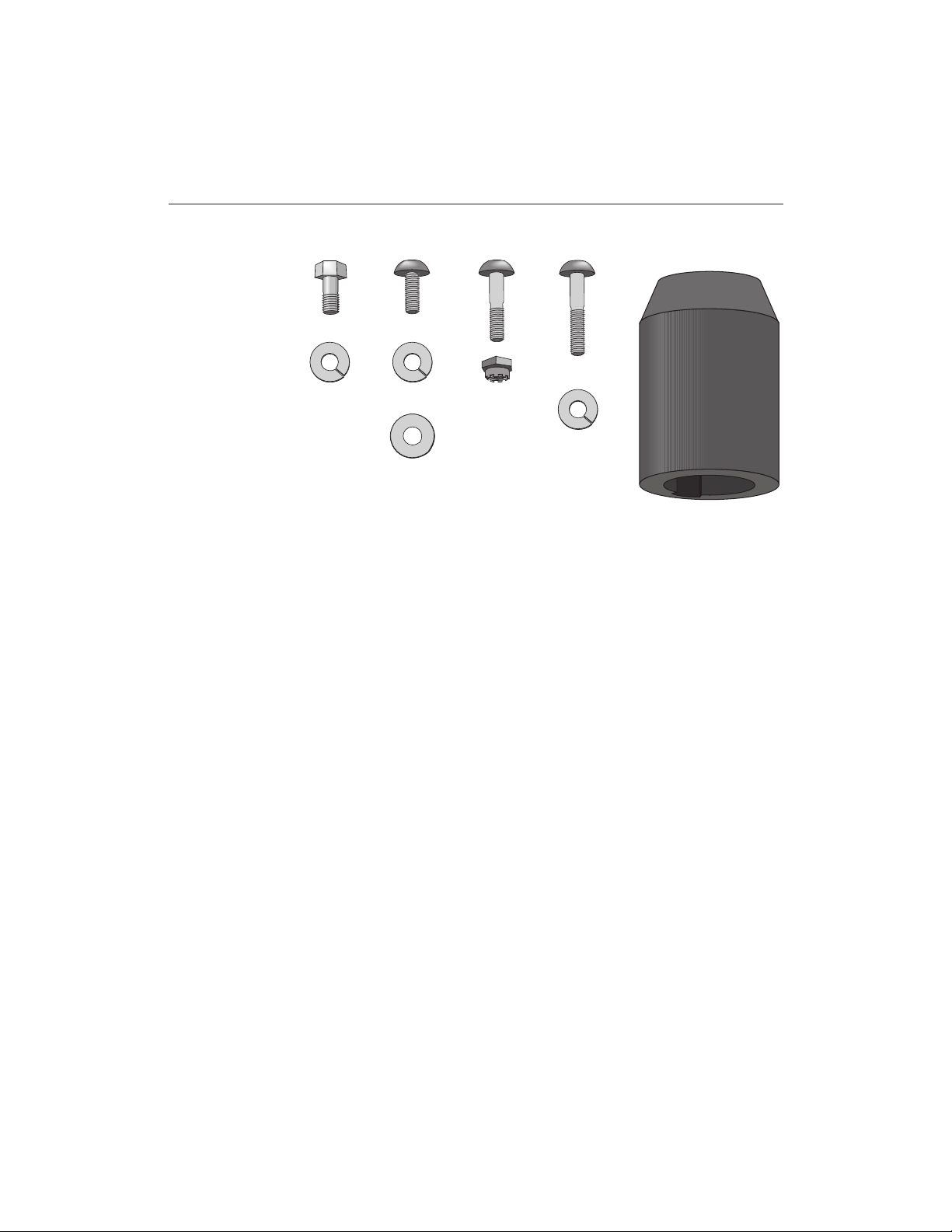
Diagram 2
Hardware kit
HARDWARE KIT
Carefully unpack the parts from the shipping container. Open the hardware kit
and make sure that you have the following items:
❏ (A) four hex head screws—for installing the upper column support
❏ (B) six split lock washers—attach to screws on upper column support and
to the handrail clamp screws
AC
BDEG
J
F
H
(B)
❏ (C) three screws—for installing electronic console display
❏ (D) three split lock washers—attach to bolts on electronic console display
❏ (E) three washers—attach to bolts on electronic console display
❏ (F) two buttonhead socket bolts—for installing handrails to base frame
❏ (G) two locknuts (nylon end)—attach to lower handrail screws
❏ (H) two buttonhead screws—for installing handrails to handrail clamp
❏ (J) two handrail rubber boots—for covering lower handrail screws at base
If any items are missing, contact your dealer. For customer suppoert, see
Obtaining Service
on page 7.
page 10
Page 11

COMMERCIAL PRODUCTS DIVISION
Setting Up the C764 Climber
You do not need any special knowledge or experience to set up a C764 climber,
however you will need assistance. Ask for one or more assistants to help you
assemble the climber.
INSTALLATION REQUIREMENTS
Follow the installation requirements below when installing the climber.
not install the climber according to the following guidelines, you could void the
Precor limited warranty.
• Set up the C764 climber on a solid, flat surface. A flat surface is required
for your safety and proper use of the climber.
• Fill out and mail the limited warranty card. The serial number is located on
a label near the power receptacle.
• Use the appropriate voltage, dedicated circuit, and grounding as speci-
fied on the climber. The C764 climber is available in a 120-volt model in the
U.S.A. and Canada. A 240-volt model is available for the European and
international markets. Refer to the climber’s identification label to determine
the voltage that your climber requires. The C764 climber’s 120-volt and 240volt models require a dedicated 15 amp circuit. A 20 amp dedicated circuit
is recommended. Failure to use a dedicated circuit might damage the unit and
void the manufacturer’s limited warranty.
CAUTION: Do not use a non-grounded outlet. Do not remove or otherwise
bypass the plug with an adapter. Electrical damage can occur if the C764
climber is connected to an improper power source.
ADDITIONAL TOOLS NEEDED
Obtain the following tools before assembling the C764.
If you do
❏ Standard set of hex keys
❏ ½-inch socket wrench with an extension
❏ ½-inch box-end wrench or crescent wrench
❏ ⁷₁₆-inch box-end wrench
ASSEMBLY INSTRUCTIONS
To assist you in the assembly of the climber, the items in the hardware kit, shown
in Diagram 2, correspond to a particular letter in the alphabet. These letters
appear throughout the assembly instructions. Refer to Diagram 2, while performing the following steps:
1. Unpack the climber and remove the packing materials from the handrails,
upper column support, display console, handlebars, and base frame
assembly.
CAUTION: To avoid injury and ensure your safety, you need assistance to lift the climber off the pallet and place it on the floor. Do not
drop the unit.
page 11
Page 12
COMMERCIAL PRODUCTS DIVISION
2. Remove the climber from the shipping pallet. Be sure to remove the lag bolt
that holds the climber on the pallet. The lag bolt is located under the right foot
pedal next to the casing. Ask for assistance to lift the climber off the shipping
pallet.
3. Make sure that the climber is unplugged and turned OFF. Do not assemble
the C764 climber if it is plugged into a power outlet.
4. Take the following steps to secure the upper column to the base frame
assembly. Refer to Diagram 3.
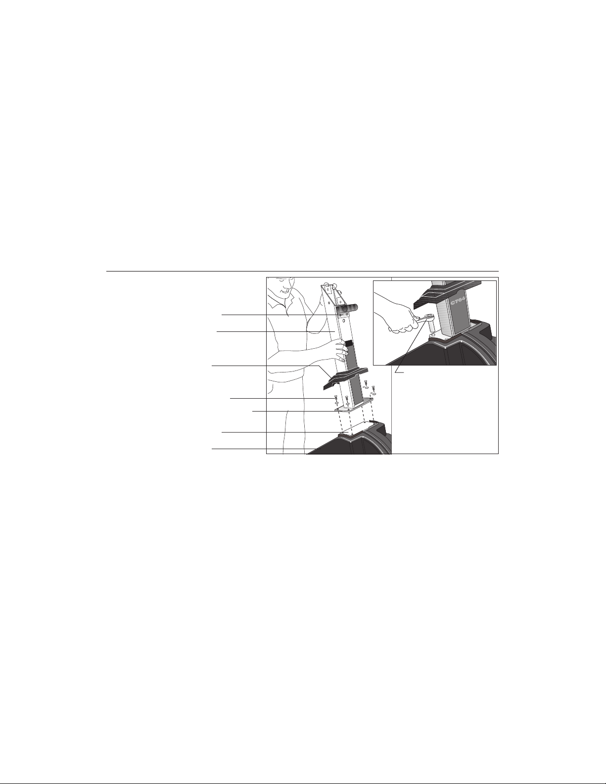
Diagram 3
Secure upper column
to base assembly.
Handrail clamp
Upper column
Rubber boot
4 screws (A) with split
lock washers (B)
Upper column bracket
Mounting plate
Base frame
Use a 1/2-inch socket
wrench to secure the
upper column to base
assembly.
a. Remove four split washers (B) four hex head screws (A) from in the
Hardware kit. Place one split washer onto each screw.
b. Slide the rubber boot up the column to expose the mounting plate.
c. Position the upper column above the mounting plate so that the handrail
clamp (on the upper column) faces the foot plates.
d. Align the holes and insert the four screws (A) through the upper column
bracket and into the base frame mounting plate. See Diagram 3. Finger
tighten each screw.
page 12
e. Obtain a 1/2-inch socket wrench and alternately tighten each screw until
all four are tight against the bracket. Do not overtighten.
Page 13
COMMERCIAL PRODUCTS DIVISION
Diagram 4
Remove the handrail
clamp.
Handrail clamp
Nylock nuts inside upper
column
Upper column
5. Remove the handrail clamp from the upper column. Diagram 4. Nylock® nuts
inside the upper column secure the two handrail clamp screws. Hold the two
screws with a 3/16-inch Allen wrench and use a 1/2-inch box end wrench to
loosen the nuts. Carefully place your hand inside the upper column to catch
the nuts as they become loose. Set the fasteners and clamp aside for use
in a later step.
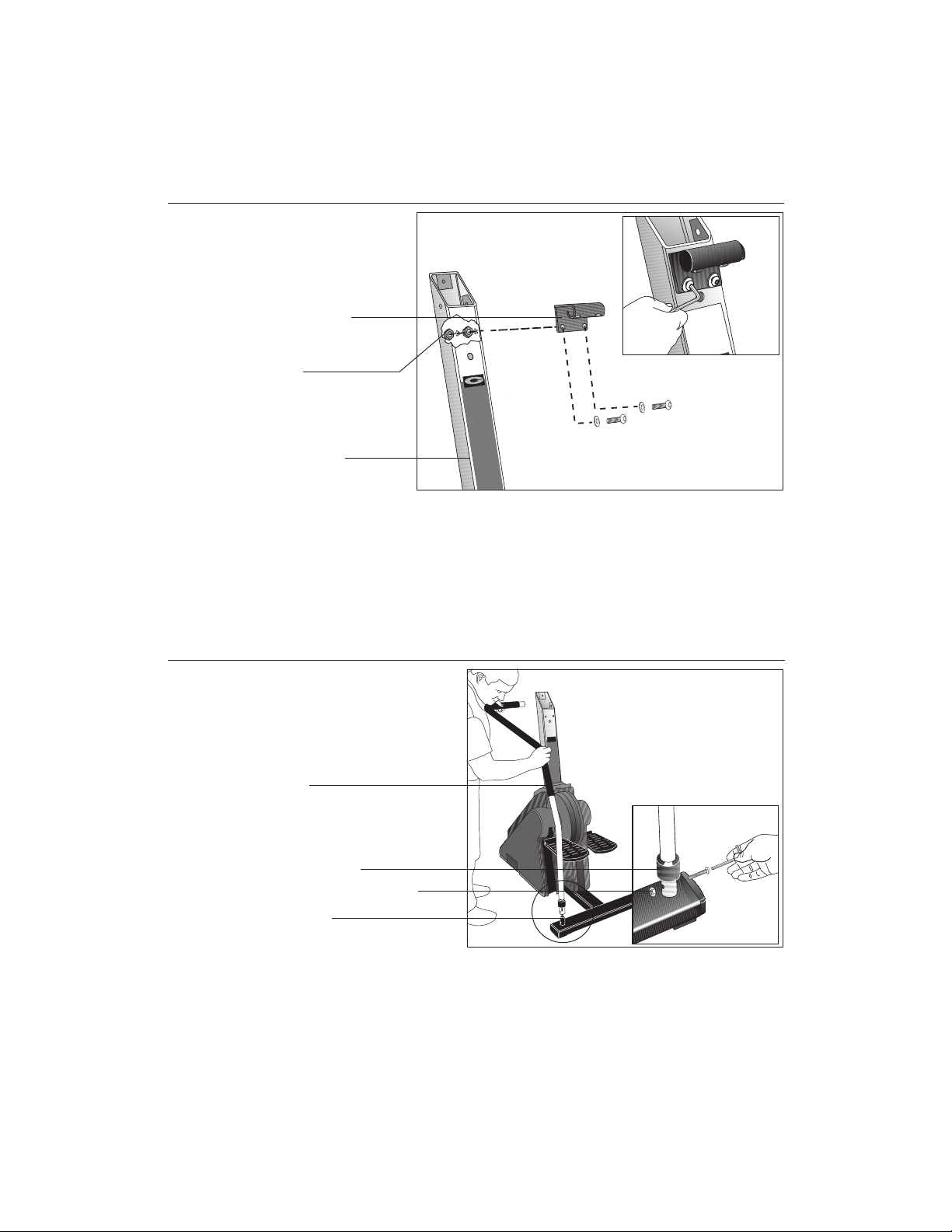
Diagram 5
Attach the lower portion of the
handrails to the C764 and
upper portion to the handrail
clamp.
Handrail
Handrail boot (J)
Screw (F) with locknut (G)
Base mount
6. Have an assistant hold the upper portion of the handrails while you slide a
handrail boot (J) onto the base of each handrail. Refer to the inset in Diagram
5. Be sure to mount the bell-shaped boot properly. The wide portion of the “bell”
should be facing toward the base.
7. Place the end of the handrails onto the base mounts and align the mounting
holes. Diagram 5. Insert two screws (F) through each handrail mount. Attach
a locknut (G) to the opposite end of the screw and finger tighten.
Do not
wrench tighten the screws at this point.
page 13
Page 14
COMMERCIAL PRODUCTS DIVISION
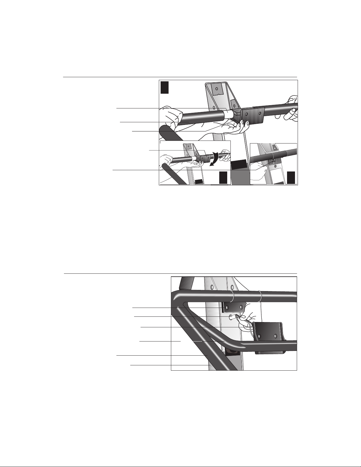
Diagram 6
Attach the upper portion
of the handrails to the
handrail clamp.
Handrail
Foam grip
Handrail clamp
Rotate handrail clamp.
Secure handrails in
clamp.
1
2 3
8. Attach the upper portion of the handrails to the handrail clamp (removed in
step 5). Position the handrails as shown in Diagram 6, #1. Slide the handrails
into the clamp.
9. Rotate the handrail clamp so that it aligns with the mounting holes on the
upper column. Diagram 6, #2.
10. Secure the handrails to the handrail clamp. Insert two screws (H) with split
lock washers (B) through the handrail clamp. Tighten the screws using the
appropriate hex key. Diagram 6, #3.
column at this point.
Do not attach the clamp to the upper
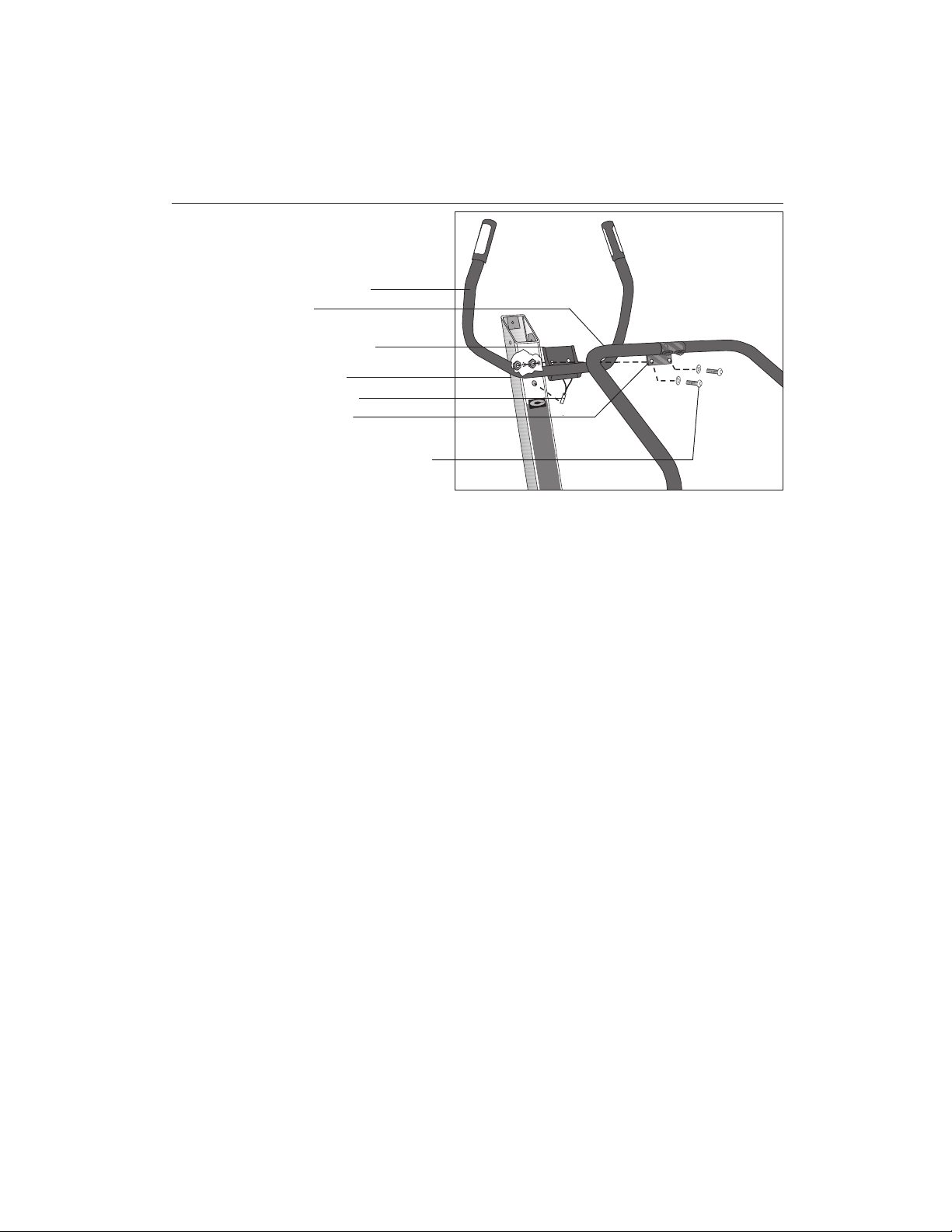
Diagram 7
page 14
Align the vertical handlebars
and handrail clamp and route
the heart rate cable.
Handrail clamp
Heart rate cable
Handlebar bracket
Vertical handlebar
Handrail
Upper column
11. Slide the vertical handlebar into position. Diagram 7. The handlebar bracket
is sandwiched between the upper column and the handrail clamp. Have your
assistant open about a two inch gap between the upper column and the
handrail clamp by pulling or pushing the handrails toward the foot plates.
Position the handlebar bracket between the upper column and handrail
clamp.
12. Thread the heart rate cable through the hole in the upper column. Diagram 7.
Page 15
COMMERCIAL PRODUCTS DIVISION
Diagram 8
Secure the handlebar bracket
and handrail clamp to the
upper column.
Vertical handlebar
Handrail
Handlebar bracket
Upper column
Heart rate cable
Handrail clamp
Reinsert screws and
washers removed in step 5.
13. Align the holes in the handlebar bracket and the holes in the handrail clamp
with the two holes in the upper column. Diagram 8. Insert the two screws with
washers that were removed in step 5.
14. Replace the nylon-end nuts (removed in step 5) onto the end of the screws.
Finger tighten the nuts while you hold the screws with a 3/16-inch hex key.
Secure each nut by grasping it with a 1/2-inch box-end wrench (or crescent
wrench) and tightening the screws with the hex key. Refer to Diagram 8.
15. Secure the handrails to the base assembly. Return to the lower handrail
mounts and securely tighten the two screws (F). Hold onto the locknut (G)
with a ⁷₁₆-inch box-end wrench and tighten the screws using the appropriate
hex key. Slide the handrail boot down over the screw and locknut. Refer to
Diagram 5.
page 15
Page 16

COMMERCIAL PRODUCTS DIVISION
Diagram 9
Attach the display
console.
Cables found in back of
the display console.
1
Route the ribbon
cable through the
upper column.
Connect the heart rate
cable.
3
16. Attach the display console by taking the following steps:
a. Gently unwrap the cables found in the back of the display console.
Diagram 9, #1.
b. Hold the display console above the upper column and route the ribbon
cable down through the column and out its base. Diagram 9, #2.
c. Carefully lower the display onto the upper column so that your assistant
can connect the heart rate cables. Diagram 9, #3. Gently place any
excess cable into the opening on the back of the display console.
2
Important: Be sure not to crimp or pinch the cables. Damaged cables
are not covered by the Precor Limited Warranty.
page 16
Page 17

COMMERCIAL PRODUCTS DIVISION
Diagram 10
Secure the display
console to the upper
column.
Display console
Upper column
Screws (C), lock washers
(D), and washers (E)
Make sure that the base
of console is parallel to
the top of the handrail
clamp.
d. Remove three screws (C), lock washers (D) and washers (E) from the
Hardware kit. Place the lock washers and then the washers onto the
screws. Align the mounting holes on the display with the upper column
and insert the screws so that the washers are against the upper column.
Diagram 10.
Note: Be sure that the bottom of the display is parallel with the top of the
handrail clamp.
e. Alternately tighten each screw using the appropriate hex key. Do not
overtighten.
page 17
Page 18

COMMERCIAL PRODUCTS DIVISION
Diagram 11
Connect the ribbon cable
and complete the C764
assembly.
Pull ribbon cable through
upper column.
Tabs on receptacle
Connect the ribbon
cable.
Push excess cable into
upper column.
Lower the rubber boot
over the base mounting
plate.
1
2
3 4
17. Connect the ribbon cable. Return to the upper column where it is mounted
to the base assembly and take the following steps:
a. Pull the ribbon cable out of the upper column. Diagram 11, #1.
b. Open the tabs on the ribbon cable receptacle. Plug the connector into
the receptacle. Diagram 11, #2. Make sure that all pins are aligned and
fully engaged. The connector is designed to engage in one direction
only. Do not force the connector into the receptacle.
c. Gently push the excess ribbon cable and the connectors up into the
column support. Diagram 11, #3.
18. Lower the rubber boot over the base mounting plate. Make sure that the boot
seats correctly over the plastic casing. Diagram 11, #4.
You have completed the installation of the C764 vertical handlebars with the
heart rate feature. To learn more about the heart rate feature continue reading.
page 18
Page 19

COMMERCIAL PRODUCTS DIVISION
Programmable Options on the C764 Climber
These next few pages provide information that lets you customize the C764 for
your Club. It is not information that your customer needs to see. This section
covers the following information about how to:
• select the units of measure
• set maximum workout and pause times
• customize a course
Note: If your customers are interested in the learning more about the C764, you
may wish to direct them to the manual available on Precor’s web site
(www.precor.com). (The manual, which appears on the web site, does not
contain the information found in this section.)
CHANGING THE CLUB SETTINGS
The Club Custom Mode lets you customize your C764 climber with these
features:
• Measurement system—You can choose between U.S. Standard or Metric.
Typically, the climber you buy is set to U.S. Standard.
• Maximum workout time—You can set a workout time limit between 10 and
240 minutes in variable increments (see the list below). For example, if a you
set the maximum workout time to 20 minutes, the climber allows users to
specify a workout time from 10 to 20 minutes. Users could not specify a
workout time longer than 20 minutes. When you buy the C764, the workout
limit is set at 60 minutes. The incremental displays vary as shown below:
Time settings: Displays increments of: For example:
10 to 20 minutes 1 minute 11, 12, 13,...
20 to 60 minutes 5 minute 25, 30, 35,...
60 to 240 minutes 15 minute 75, 90, 105,...
• Custom courses (C764 only)—You can design two custom courses to meet
your customers’ needs. A blank grid sheet, on page 28, provides a work sheet
to help design your course.
Accessing the Club Custom Mode requires combining specific keys on the
electronic console. This design helps secure the climber from unauthorized
access and changes.
To use the Club Custom Mode, take the following steps:
1. Make sure that the climber is placed in an appropriate location and
plugged in.
2. If necessary, turn ON the climber using the ON/OFF power switch. This
switch is located near the power cable.
3. When the start-up prompt “PRESS ENTER FOR PROGRAMS OR PRESS
QUICKSTART” appears, access the Club Custom Mode by simultaneously
pressing all three CHANGE keys.
page 19
Page 20

COMMERCIAL PRODUCTS DIVISION
Diagram12
R
C764
WORK LEVEL
RATE PER MINUTE
46
43
40
37
34
30
27
24
21
20
18
17
15
14
12
11
9
8
6
For information about Precor products, call 1-800-859-8404.
CAUTION
Do not allow children and people unfamiliar with climber operation
on or near the climber. Before beginning any fitness program, you
should have a complete physical examination by your physician.
If you feel faint or dizzy, stop exercising immediately.
1 2 3 4 5 6 7 8 9 01
Steps
FeetMeters
225
150
210
140
195
130
180
120
165
110
150
100
135
90
120
80
105
70
98
65
90
60
83
55
75
50
45
68
40
60
35
53
30
45
25
38
20
30
% COMPLETED 1 2 3 4 5 6 7 8 9 010 0 0 0 0 0 0 0 0 0
RESET
www.precor.com
TIME FLOORS CLIMBED FLOORS PER MINUTE
UP
CALORIES
CALORIES PER MINUTE
HORIZONTAL DISTANCE
OFF
equivalent in miles / kilometers
ENTER
SEGMENT TIME LEFT
WATTS
USA
METS
OFF
1 Step = 8 inches Horizontal Distance = the energy
CHANGE CHANGE CHANGE
WORK LEVEL / SPEED
DOWN
STEPS PER MINUTE
FEET PER MINUTE
METERS PER MINUTE
OFF
1 Floor = 10 Feet (3 meters)
QUICK START
4. Release all three keys when the prompt “CHOOSE UNITS” appears on the
display as shown in Diagram 12. Use the ▼ or ▲ key to select the
measurement system, either Metric or U.S. Standard.
5. The prompt “MAX WORKOUT ” appears. Use the ▼ or ▲ key if you want
to designate a time limit between 10 and 240 minutes. The amount of time
you choose limits the length of a person’s workout. Press ENTER when the
desired time limit appears.
Note: Continuous pressure on the arrow key lets you scroll through the
numbers being displayed.
6. On the C764 climber, the “MODIFY CUSTOM” prompt appears. If you plan
to customize a program, select “YES” and refer to
Course on the C764 Climber
below. If you do not want to customize a
Designing a Custom
program at this time, select “NO” by pressing the ▲ key.
The “PRESS ENTER FOR PROGRAMS OR PRESS QUICKSTART” prompt
appears, and the climber is ready to use.
DESIGNING A CUSTOM COURSE ON THE C764 CLIMBER
The C764 climber lets you design two custom courses: CUSTOM 1 and
CUSTOM 2. To program these courses, you need to press a specific combina-
tion of keys on the electronic console. This design helps secure the climber from
unauthorized access and changes.
Important: A blank course profile grid is provided on page 37 to help you design
a custom course on paper prior to programming it into the climber.
page 20
Page 21

COMMERCIAL PRODUCTS DIVISION
To design a custom course, take the following steps:
1. Check to see that the climber is turned ON. If it is turned OFF, turn it ON
using the ON/OFF power switch. This switch is located near the power
cable.
2. The initial start-up prompt, “PRESS ENTER FOR PROGRAMS OR PRESS
QUICKSTART” appears.
3. Access the custom course mode by pressing and holding all three CHANGE
keys simultaneously.
4. Release the keys when the prompt “CHOOSE UNITS” appears. Answer
each prompt as described in the previous section titled,
Custom Mode
.
Using the Club
5. Once the prompt “MODIFY CUSTOM” appears, use the ▼ key to select
YES. The prompt, “CHOOSE COURSE” appears.
6. The program number (1 or 2) appears in the left window display. To select
the other number, press the ▼ or ▲ key. When the desired course number
appears, press ENTER.
Diagram 13
R
C764
WORK LEVEL
RATE PER MINUTE
46
43
40
37
34
30
27
24
21
20
18
17
15
14
12
11
9
8
6
For information about Precor products, call 1-800-859-8404.
CAUTION
Do not allow children and people unfamiliar with climber operation
on or near the climber. Before beginning any fitness program, you
should have a complete physical examination by your physician.
If you feel faint or dizzy, stop exercising immediately.
1 2 3 4 5 6 7 8 9 01
Steps
FeetMeters
225
150
210
140
195
130
180
120
165
110
150
100
135
90
120
80
105
70
98
65
60
90
55
83
50
75
45
68
40
60
35
53
30
45
25
38
20
30
% COMPLETED 1 2 3 4 5 6 7 8 9 010 0 0 0 0 0 0 0 0 0
RESET
www.precor.com
TIME FLOORS CLIMBED FLOORS PER MINUTE
UP
CALORIES
CALORIES PER MINUTE
HORIZONTAL DISTANCE
OFF
equivalent in miles / kilometers
ENTER
SEGMENT TIME LEFT
WATTS
USA
METS
OFF
1 Step = 8 inches Horizontal Distance = the energy
CHANGE CHANGE CHANGE
WORK LEVEL / SPEED
DOWN
STEPS PER MINUTE
FEET PER MINUTE
METERS PER MINUTE
OFF
1 Floor = 10 Feet (3 meters)
QUICK START
7. The course profile window appears and provides a 10 x 20 (10 cells high by
20 cells wide) grid in which to design a course. The prompt, “DRAW
COURSE” appears in the right display window. See Diagram 13.
Note: A blank course profile grid is provided on page 37 to help you design
your course prior to entering it into the climber’s memory.
page 21
Page 22

COMMERCIAL PRODUCTS DIVISION
8. Initially, the course profile appears as a flat line four cells high. However, if
the course has been previously modified and saved into the climber’s
memory, that custom course profile appears instead.
Your position on the course is indicated by a blinking cell. Any changes that
you make occur only in that column. Begin modifying the course profile one
cell at a time using the ▼ or ▲ key. You increase the step rate (causing the
foot pedals to travel faster) when you add cells to a column by pressing the
▲ key. The opposite occurs when you press the ▼
key. If you are satisfied
with the column, press ENTER to save it as part of the course profile. The
cell at the top of the next column to the right begins to blink.
Note: Once you have started “drawing” the course profile you cannot exit
this function until you press ENTER after the 20th cell.
9. The blinking cell indicates your position. Press ENTER to accept the column
as it is or use the ▼ or ▲ key to change it. Once you modify the 20th column
and press ENTER, the software saves the course profile and the prompt
“MODIFY CUSTOM” appears.
10. If desired, customize the other program by following steps 5 through 9.
11. Once you have completed customizing the programs, select “NO” at the
“MODIFY CUSTOM” prompt and the initial start-up prompt, “PRESS
ENTER FOR PROGRAMS OR PRESS QUICKSTART” appears.
The C764 climber is ready to use. To review your custom course modifications,
do not use QUICKSTART. Instead, press ENTER at the initial start-up prompt
and select the appropriate custom course number at the “SELECT COURSE”
prompt. See the section titled,
Exercising on the C764 Climber
.
page 22
Page 23

COMMERCIAL PRODUCTS DIVISION
Using the C764 Climber
The C764 Climber is designed so users can work out with minimal instruction or
training. The directions on the console and the prompts on the display will guide
a user through the entire workout session. Before the climber is used, however,
we recommend that you familiarize yourself with it so it will be used safely and
effectively. This section covers the following information:
• instructions for turning the climber ON and OFF
• an overview of the features provided on the electronic console
• instructions for exercising on the climber
• an explanation about using manual mode and the QUICKSTART key
• an explanation about using the interval and random courses
TURNING THE CLIMBER ON AND OFF
Use the ON/OFF power switch to turn the climber ON and OFF. This switch is
located near the power cable.
UNDERSTANDING THE DISPLAY CONSOLE
Once the C764 climber is set up, it is ready to use. There are no complex
instructions to follow or mandatory programming steps required to operate the
climber. Choose either the
the manual program, or the
information. The easy-to-understand prompts let you specify how long you want
to work out, select one of 15 workout programs and then specify how hard you
want to work.
QuickStart
setup mode
feature which lets you immediately start
which prompts you for more specific
page 23
Page 24

COMMERCIAL PRODUCTS DIVISION
As you exercise, the electronic console provides motivation and presents
constant feedback about your progress. An explanation of each feature on the
C764 console follows Diagram 14 .
Diagram 14
R
C764
WORK LEVEL
RATE PER MINUTE
46
43
40
37
34
30
27
24
21
20
18
17
15
14
12
11
9
8
6
For information about Precor products, call 1-800-859-8404.
CAUTION
Do not allow children and people unfamiliar with climber operation
on or near the climber. Before beginning any fitness program, you
should have a complete physical examination by your physician.
If you feel faint or dizzy, stop exercising immediately.
1 2 3 4 5 6 7 8 9 01
Steps
FeetMeters
225
150
210
140
195
130
180
120
165
110
150
100
135
90
120
80
105
70
98
65
90
60
83
55
75
50
68
45
60
40
53
35
45
30
38
25
30
20
% COMPLETED 1 2 3 4 5 6 7 8 9 010 0 0 0 0 0 0 0 0 0
RESET
www.precor.com
TIME FLOORS CLIMBED FLOORS PER MINUTE
UP
CALORIES
CALORIES PER MINUTE
HORIZONTAL DISTANCE
OFF
equivalent in miles / kilometers
ENTER
SEGMENT TIME LEFT
WATTS
USA
METS
OFF
1 Step = 8 inches Horizontal Distance = the energy
CHANGE CHANGE CHANGE
WORK LEVEL / SPEED
DOWN
STEPS PER MINUTE
FEET PER MINUTE
METERS PER MINUTE
OFF
1 Floor = 10 Feet (3 meters)
QUICK START
The electronic console keypad has two sets of keys. The upper set (CHANGE)
affect the electronic console displays, the lower set (RESET, WORK LEVEL/
SPEED, DOWN/UP, ENTER, and QUICKSTART) affect the function and
features of the climber.
Note: Before beginning a workout, the ▼ or ▲ keys provide a way to answer the
prompts being displayed on the electronic console.
page 24
CHANGE keys: Each of three “change” keys appear below their respective
column of functions. Display a particular function by pressing the appropriate
CHANGE key until the function’s indicator lights. For example, if the CALORIES
indicator is lit, you can change the display to show the distance (feet or meters)
that you have travelled since you started your workout by pressing the CHANGE
key until the HORIZONTAL DISTANCE indicator is lit.
RESET: While you are answering the setup prompts, you can cancel the
program, clear the display, and return to the initial start-up prompt, by pressing
RESET. The initial start-up prompt, “PRESS ENTER FOR PROGRAMS OR
PRESS QUICKSTART” appears on the display. You can then begin another
exercise program. During a workout on the C764 climber, pressing RESET exits
the course or program, erases the workout statistics, and displays the start-up
prompt after the climber performs a systems diagnostic test. The foot pedals
return to a very slow fall rate during this time and do not change until you return
to a program or choose a new course.
Page 25

COMMERCIAL PRODUCTS DIVISION
WORK LEVEL/SPEED: The ▼ or ▲ keys change the “work level” by changing
the step rate which increases/decreases the degree of effort. You decrease the
step rate (causing the foot pedals to travel slower ) and increase the resistance
when you press the ▼ key. The opposite occurs when you press the ▲ key.
ENTER: When you turn ON the climber, several prompts appear before you
start your workout. Each prompt needs to be addressed and then “entered” into
the climber’s memory by pressing the ENTER key.
QUICKSTART: If you wish to use the manual program, you can bypass the
setup prompts by pressing the QUICKSTART key. When you begin working out,
the amount of time you have been on the climber and the number of floors
climbed appears on the electronic console display.
Note: The weight setting defaults to 150 pounds (70 kb) so all calorie calculations and their associated displays are based on a body weight of 150 pounds.
The time selection defaults to the club limit set in memory. You cannot change
the weight or time setting if you use the QUICKSTART option.
GRAPHIC DISPLAY ON THE C764 CLIMBER
The left window display on the C764 electronic console provides graphic
information about your workout session. The course profile that appears in the
left window display corresponds to the program you selected. As you proceed
through your workout, your position is indicated by a blinking cell.
WORK LEVEL: Shows the selected effort level, from 1 to 10. The higher the
number, the faster your step rate becomes. You can change the work level
anytime during a workout by using the WORK LEVEL/SPEED ▼ or ▲ keys to
increase or decrease the degree of effort in your workout.
Note: A WORK LEVEL indicator does not appear when you use the manual or
interval programs.
RATE PER MINUTE: Provides a comparison chart to help you determine the
number of meters, feet, or step rate at which you are travelling. This chart
corresponds to the bar graph on the C764. You can also use the comparison
chart to convert a highlighted numerical display (STEPS PER MINUTE, FEET
PER MINUTE, or METERS PER MINUTE) found on the far right of the console.
page 25
Page 26

COMMERCIAL PRODUCTS DIVISION
SMARTRATE® (C764 only) When the Precor optional heart rate receiver has
been properly installed and the user wears the POLAR® chest strap or holds
onto the heart rate grips, a blinking segment in the bar graph appears at the
bottom of the display. If the user entered an accurate age (completed during the
setup prompts), the blinking segment shows the zone that the user’s heart rate
is in: either Weight Loss or Cardiovascular. Refer to
Understanding SmartRate
Important: The SmartRate blinking indicator light and the heart rate display only
appear when the Precor heart rate receiver is installed in the electronic display
and the chest strap transmitter is used. The SmartRate indicator lights do not
appear when a user presses the QuickStart key. If the SmartRate lights appear,
but do not blink, it means that a receiver is installed, but the user is not wearing
the chest strap transmitter or is not holding onto the heart rate grips properly.
RIGHT DISPLAY ON THE C764 CLIMBER
.
Prior to your workout, prompts appear in the
you need to take appears in the
lower
top
right display window. The action
window. Once you begin a workout, the
top window indicates the TIME, DISTANCE (floors climbed), and SPEED (floors
per minute). You can determine what information will appear in the lower window
by pressing the CHANGE keys and highlighting a particular feature.
TIME: Displays the time that has elapsed since beginning a specified program
or workout. Use this display to pace yourself during a workout.
FLOORS CLIMBED: Shows the equivalent vertical distance that you have
travelled during your workout. A floor is equivalent to 10 feet or 3 meters.
Note: During a workout on the C764 climber, pressing RESET exits your
program and displays the start-up prompt after the climber performs a systems
diagnostic test. The foot pedals return to a very slow fall rate during this time and
do not change until you return to a new course or program.
FLOORS PER MINUTE: Once you begin a workout, the vertical speed at which
you are travelling appears in this display.
SEGMENT TIME LEFT: Appears only on the C764 climber and indicates the
amount of time left in a particular column (or segment) before the cell at the top
of the next column begins blinking. During the start-up prompts, you enter a
workout time. When the course is displayed, each column corresponds to the
“workout time divided by 20” because 20 columns exist for each course.
page 26
WATTS: Indicates the amount of energy currently being expended.
METS: Displays the metabolic units associated with your workout.
Page 27

COMMERCIAL PRODUCTS DIVISION
OFF: If you move the indicator light to OFF using the CHANGE key, no
information is displayed for that column.
CALORIES: Provides the cumulative number of calories burned.
Note: The numbers that appear in the CALORIES and CALORIES PER
MINUTE displays are weight-dependent. During the start-up prompts, entering
a weight close to your actual body weight will improve the accuracy of the
numbers that appear in these displays. Pressing “QUICKSTART” only gives
appropriate results if your weight is near 150 pounds.
CALORIES PER MINUTE: Indicates the number of calories per minute.
HORIZONTAL DISTANCE: Converts the number of floors climbed into a
horizontal distance such as miles or kilometers. Use the
Club Custom Mode
to
select the measurement system: U.S. standard or Metric.
STEPS PER MINUTE: When you choose this display, the pace (step rate) at
which you are climbing appears. A conversion chart on the left of the console
exists to help you determine or convert the step rate into other units of measure.
FEET PER MINUTE: Displays the distance in feet per minute that you are
travelling. Use the conversion chart on the left of the console to help you
determine your step rate.
METERS PER MINUTE: Displays the distance in meters per minute that you are
travelling. Use the conversion chart on the left of the console to help you
determine your step rate.
HEART RATE: Helps you monitor your heart rate and stay within your target
zone. Check with the club owner or manager to make sure the optional heart rate
receiver is installed in the C764 electronic console. To display your heart rate
while you work out, press the CHANGE key until the indicator lights next to the
words “HEART RATE” on the console’s label.
Note: You must wear the Precor chest strap to transmit your heart rate to the
receiver in the electronic console. Refer to your
Owner’s Manual
.
Precor Heart Rate Option
page 27
Page 28

COMMERCIAL PRODUCTS DIVISION
Working Out on the C764 Climber
This section explains how to exercise on the climber and introduces you to
certain features that you might use during your workout.
PAUSING DURING YOUR WORKOUT
The C764 climber has a two-minute, auto-pause feature that occurs when you
step off the climber. If no movement is detected on the foot pedals for two
minutes, the climber resets, clears the workout statistics, and displays the initial
start-up prompt.
ENDING YOUR WORKOUT
To end a workout, simply step off the climber. The auto-pause feature explained
above gives the user time to review the workout statistics and, then, resets the
climber.
COOLING DOWN AFTER YOUR WORKOUT
A cool-down period exists on the C764 climber when a user reaches the end of
a course. The five-minute, cool-down period lets the user vary the step rate while
calorie count and distance continues to accumulate on the workout statistics.
After the five-minute cool down, a two-minute period allows the user to reflect
upon their workout statistics. During the two-minute period, the prompt “FINAL
WORKOUT RESULTS” appears. Pressing RESET or letting the two-minute
period elapse, causes the start-up prompt to appear.
Note: The five-minute, cool-down period on the C764 activates automatically
only when a user reaches reach the end of a course.
UNDERSTANDING SMARTRATE
The C764 software incorporates the latest in cardiac monitoring to provide
SmartRate®—a visual aid that lets the user know where his or her heart rate is
at a glance. When the user grips the touch-sensitive handlebars or wears the
POLAR® chest strap, the graph on the display lights up with colored cells to
indicate exercise intensity. A specific percent of the user’s heart rate appears as
a blinking cell within that zone.
SmartRate simplifies the correlation between heart rate and exercise. A user
doesn’t have to stop concentrating during a workout to find their pulse anymore.
If a user enters an age during the setup prompts, SmartRate performs all the
calculations and displays a blinking cell that shows the user which zone he or
she is in: cardiovascular or weight loss.
Using SmartRate during a workout with any C764 course helps maximize the
user’s weight loss or cardiovascular fitness regimen. While a user works out in
a particular course, you as trainer or club manager, could show him or her the
SmartRate display and suggest changing the work level, moving to a different
cadence (step rate), or increasing/decreasing step height to position his or her
heart rate in the desired SmartRate zone.
®
page 28
Page 29

COMMERCIAL PRODUCTS DIVISION
Diagram 15
Target zones.
HEART RATE TARGET ZONES
200
190
180
170
160
RECOMMENDED CARDIOVASCULAR ZONE
RECOMMENDED WEIGHT LOSS ZONE
25 30 35 40 45 50 55 60 65 70 75
20
MAX.
HEART
RATE
Cardio
Zone
Weight
Loss
Zone
YOUR HEART RATE
150
140
130
120
100
90
80
70
YOUR AGE
As shown in Diagram 15, when a user maintains his or her heart rate between
70% and 85% of their maximum aerobic heart rate, overall improvement occurs
to his or her cardiorespiratory fitness level. If a person maintains his or her heart
rate between 55% and 70% of their maximum aerobic heart rate, he or she is
burning enough calories that, when continued on a regular basis for 30 minutes
or more, provides the greatest fat-burning (weight loss) benefits.
USING THE HEART RATE CAPABILITY
Important: A user can access SmartRate and utilize all heart rate function, only
if he or she grasps the heart rate grips ont he handlebars or sears a POLAR
chest strap. See
not appear when you use the QuickStart key.
A user can make each program on the C764 a heart rate interactive course by
monitoring and maintaining his or her heart rate in the SmartRate zone best
suited for their specific needs.
Before utilizing the heart rate capabilities (SmartRate), take time to read the
following guidelines. Make sure that you informs your customers as well.
• Consult with your physician before engaging in any vigorous exercise. Do not
use SmartRate until authorized by your physician.
• Slow down and stop the workout immediately if you experience any pain or
abnormal symptoms.
• Gently stretch your lower body and back before and after the test to help
prevent stiffness or soreness.
Obtaining Service
on page 7. The SmartRate indicator lights do
®
page 29
Page 30

COMMERCIAL PRODUCTS DIVISION
• Know your heart rate (pulse) and your physician-recommended heart rate
target zone. Individual heart rates vary according to several physiological
factors and may not correspond directly with the zone shown in Diagram 15.
• You should not use the heart rate interactive capabilities (SmartRate) if you
are taking any medications that either speed up or slow down your heart rate.
• Keep in mind that you are working with very sensitive equipment and upper
body movement should be kept to a minimum.
• After putting on the POLAR® chest strap, turn the C764 ON, stand on the foot
pedals, and face the display console for a minimum of 15 seconds. This
allows the unit to acknowledge the presence of the transmitter.
While the C764 software monitors your heart rate, you have the capability to
maintain it within the cardiovascular or weight loss zones by changing the step
height, the cadence (step rate), or the resistance (work level) felt through foot
plates. Increasing or decreasing these aspects affects your work effort and heart
rate. Digitally, your heart rate can appear in the right window display. Use the
CHANGE key to highlight the HEART RATE indicator.
USING THE HEART RATE “TOUCH-SENSITIVE” GRIPS
The touch-sensitive grips on the vertical handlebars transmit the user’s heart rate
from the user’s palms to the heart rate receiver located in the display console.
The user’s heart rate appears on the display during a workout. The HEART RATE
indicator lights and blinks at the same rate as the user’s pulse. This lets the user
see what his or her heart rate is doing even when the display is presenting other
workout statistics.
Note: Once the user starts a course and grasps both touch-sensitive grips, it takes
about five to ten seconds for the display to acknowledge that it is receiving a signal.
If a user releases his or her grip during a workout, a "— — —" appears on the
display. The dashes indicate that the receiver is not detecting a heart rate. To have
the heart rate reappear, the user needs to grasp the touch-sensitive strips and
maintain his or her grip on it.
HEART RATE TROUBLESHOOTING TIPS
A few easy steps can be taken before you need to call customer support
regarding heart rate problems. One of the first things to do is verify the following:
❑ A POLAR® chest strap is being worn properly by the user during a workout.
Or, the user is placing
❑ The C764 is turned ON.
both
hands on metal grips found on the handlebars.
page 30
❑ The user is working out in a selected a course. (The Heart Rate feature is
activated when a course profile appears.) Note that if the user presses
QuickStart to access a course, the SmartRate and heart rate features will
not appear.
Page 31

COMMERCIAL PRODUCTS DIVISION
Other aspects of the heart rate option are discussed below:
Detecting a Heart Beat
It may take several seconds for the heart rate receiver to detect a number of
valid
heartbeats. Once it does, the user’s heart rate appears in the Heart Rate
display.
If "— — —" appears when the Heart Rate indicator (LED) is lit and all the
previously discussed steps have been taken, then you need to do the following:
Touch-sensitive heart rate
• to conduct electrical impulses from a user’s heart,
both
touch-sensitive grips
(metal strips) must be in contact with the user’s skin. Usually, the concentration of salts in a person’s perspiration provides enough conductivity to
transmit a signal to the receiver in the display console. However some people,
because of body chemistry or erratic heartbeats, cannot use the heart rate
touch-sensitive feature on the C764. A POLAR® chest strap may provide
better results.
POLAR chest strap
• Make sure that the electrodes on the chest strap are moist and placed
properly against the skin. Sometimes, due to body chemistry, the chest strap
cannot successfully detect and transmit a heart rate. If this occurs, use the
electrolyte spray that accompanies the Precor Heart Rate Option package.
Follow the directions on the bottle. After spraying the electrode strips on the
chest strap, check to be sure that the strap is comfortably tight around the
chest and centered in the middle of the user’s chest.
• Another possibility which can cause erratic readings is that the chest strap’s
battery may be dead. To purchase a new chest strap, refer to
Service
on page 7.
Obtaining
page 31
Page 32

COMMERCIAL PRODUCTS DIVISION
EXERCISING ON THE C764 CLIMBER
The C764 comes with ten preprogrammed courses. These courses differ in the
“terrain” covered.
All ten preprogrammed C764 courses can be performed at any of the work
levels. To select the work level appropriate for your level of fitness, start with
level 1 (beginner exercise or warm-up).
In addition to the C764 preprogrammed courses, you can choose one of two
custom courses that the club has designed. Custom courses can be created and
stored in memory for future use (for instructions, see
Course on the C764 Climber
). You can also select manual, random or interval
courses which let you control your work level while the program is in progress.
For more information about using the manual, random, and interval courses,
refer to the sections following
Exercising on the C764 Climber
CAUTION: Before beginning any fitness program, you should have a
complete physical examination by your physician.
To exercise on the climber, take the following steps:
Designing a Custom
.
Note: Refer to the label on the display console for the program numbers and their
associated course profiles.
1. If the climber is OFF, turn it ON using the ON/OFF power switch. This switch
is located near the power cable. “PRESS ENTER FOR PROGRAMS OR
PRESS QUICKSTART” appears on the display console.
2. Stand on the climber with your feet firmly planted on the right and left foot
pedals.
3. Press ENTER to begin setting up the climber for your workout session. If you
plan on using the manual course, press QUICKSTART to bypass the setup
prompts.
Important: If you choose the QUICKSTART feature, skip steps 4 through
8. Using the QUICKSTART feature causes the calories display to show the
calories being burned based on a 150 pound (68 kg) person and the amount
of time you can use the climber defaults to the club limit.
4. At the “SELECT WEIGHT” prompt, specify your weight using the ▼ ❏❒ ▲
key. The console displays weight in 5-pound (2.3 kilogram) increments.
Press ENTER when your weight is displayed.
Entering your actual body weight allows the C764 climber to accurately
calculate how many calories you burn during your workout.
page 32
Page 33

COMMERCIAL PRODUCTS DIVISION
5. At the “SELECT TIME” prompt, specify the duration of your workout using
the ▼ or ▲ keys. Press ENTER when the correct time is displayed. The
length of time allowed for a workout can be limited by
Mode
discussed on page 9. When specifying a workout time, you can
Using the Club Custom
choose any time up to, but not longer than, this limit. For example, if the
club’s time limit is set at 20 minutes, you can set a workout time from 10 to
20 minutes.
6. At the “SELECT COURSE” prompt, choose the course number or name
using the ▼ or ▲ key. When the desired course number or name is
displayed, press ENTER. Refer to the label on the display console for the
program numbers and their associated course profiles.
7. Once you decide on a work level, press ENTER. You are ready to begin your
workout.
8. Continue your workout and maintain your exercise intensity by varying the
work level and step rate. To pause during your workout, simply step off the
climber. A two-minute pause occurs before the climber resets your workout
statistics. Refer to
Pausing Your Workout
for more information.
Note: On the C764 climber, you can change the work level by pressing the
WORK LEVEL ▼ or ▲ keys while you work out. Doing this affects the entire
level of the course profile. In Manual or Interval modes, you affect the level
of each cell in the profile,
not
the entire course.
9. When the selected time frame or exercise program ends, review your
workout statistics. Press RESET to clear the displays.
We recommend that you keep track of your workouts by writing them down. This
way you can monitor your progress toward your fitness goals and also use the
information as a reference in planning interesting and challenging workouts in
the future. A form for recording your workout statistics is provided on page 39.
page 33
Page 34

COMMERCIAL PRODUCTS DIVISION
C764 Courses
The C764 lets users choose between ten preprogrammed courses. This
section provides information about the special features and functions of
the C764 courses.
USING MANUAL MODE AND THE QUICKSTART KEY
In addition to choosing a preprogrammed, random, interval, or custom course,
you can choose manual mode. Manual mode lets you control your work level. If
you change the work level during Manual mode, the change appears in each
individual column of the course profile while you work out.
You can choose the Manual Mode in two different ways by:
• pressing the QUICKSTART key when the “PRESS ENTER FOR
PROGRAMS OR PRESS QUICKSTART” prompt is displayed. The
QUICKSTART option bypasses the setup prompts. The weight setting
defaults to 150 pounds (68 kg) so all calorie calculations and their associated
displays are based on a body weight of 150 pounds (68 kg) which can cause
the display to show inaccurate calorie calculations. You cannot change the
weight or time settings if you use the QUICKSTART option.
• pressing ENTER at the “PRESS ENTER FOR PROGRAMS OR PRESS
QUICKSTART” prompt. This causes the climber to display a number of
prompts as explained in the previous section titled
Climber
When you choose the MANUAL program on the C764 climber, the program’s
course profile appears in the left display window and shows a flat, constant
course (4 cells high). Use the WORK LEVEL/SPEED ▼ or ▲ keys to change
work level and step rate.
Note: A low level profile represents the least amount of effort required and the
lowest number of calories burned. As you increase the work level and speed you
also increase the number of calories burned.
As you proceed through your workout on the climber, a blinking cell represents
your position in the course.
.
PREPROGRAMMED COURSES
The preprogrammed courses provide preset work levels. In these types of
courses, the work level automatically changes as a user progresses through the
course. A user can override the preset work level for each upcoming segment by
pressing either work level ▲ or ▼ key. The course profile relfects the change in
the display.
Exercising on the C764
page 34
Page 35

COMMERCIAL PRODUCTS DIVISION
CHANGING THE INTERVAL COURSE PROFILE ON THE C764
The interval courses on the C764 climber allows a user to set rest and work
intervals according to their training regimen. A user sets the work level for the first
rest and work interval (first two columns of the course) and the software takes
over from there, repeating the intervals throughout the course until the time limit
runs out or the user steps off the climber.
To set the interval for a course, take the following steps:
1. Follow steps 1 through 5 in the section titled,
Climber
. At the “SELECT COURSE” prompt, use the ▼ and ▲ keys to
Exercising on the C764
display INTERVAL. Press ENTER.
2. The INTERVAL course profile appears in the left display window. While the
cell is blinking at the top of the first column. Press the WORK LEVEL/SPEED
▼ or ▲ keys to set the “rest” speed.
3. When the cell at the top of the second column begins blinking, use the
WORK LEVEL/SPEED ▼ or ▲ keys to set the “work” speed.
After a user sets the work level and speed on the first two columns of the course
profile, the climber’s software takes over and continues repeating the rest and
work intervals throughout the remaining portions of the workout at the levels the
user selected.
Note: Anytime during a workout, the user can change the rest and work interval
levels by using the WORK LEVEL/SPEED ▼▲ keys. The climber’s software
reprograms the remainder of the course profile to the newly specified rest and
work intervals.
USING THE RANDOM COURSE ON THE C764 CLIMBER
Selecting a random course on C764 climber provides a different course profile
every time a user works out. The random program provides variable course
profiles. Every time the random course is displayed, a different course profile
appears.
The C764 climber accepts changes to the random course profile the same way
as the interval courses. If a user wishes to change the work level, they can simply
press the WORK LEVEL/SPEED ▼ or ▲ keys. The course profile changes
accordingly.
page 35
Page 36

COMMERCIAL PRODUCTS DIVISION
Maintenance
Because of its advanced design, the C764 climber requires little maintenance
beyond periodic cleaning, which is explained in this section. Keep in mind that,
as owner of this machine, you are solely responsible for its maintenance.
DANGER —
To reduce the risk of electrical shock, always unplug
the unit from its power source before cleaning it or
performing any maintenance tasks.
INSPECTION
Perform a daily inspection of the C764. Look and listen for slipping belts, loose
fasteners, unusual noises, worn or frayed power cords, and any other indications
that the equipment may be in need of service. Obtain service should you notice
Important: If you determine that the C764 is in need of service, move it away from
the main workout area and place an large “Out of Service” sign on it.
To order parts or to contact a Precor authorized service provider in your area,
refer to
Obtaining Service
on page 7.
ACCESSING THE SOFTWARE VERSION NUMBER AND ODOMETER
At the start-up prompt, press and release the WORK LEVEL/SPEED ▼▲ keys
simultaneously to find out what software version number you have and determine
the total number of floors climbed.
A software version number such as 1.05 appears in the display. Press ENTER
and the total number of floors climbed appears. Multiply that number by 10 to
determine the actual number of feet climbed. Press ENTER and the start-up
prompt appears.
CLEANING THE EQUIPMENT
Most of the working mechanisms are protected inside the casing. However, for
efficient operation, the C764 relies on low friction. To keep the friction low, the
C764 pedals and internal mechanisms must be as clean as possible.
• To clean all exposed surfaces on the C764, it is recommended that you use
a diluted solution of mild soap. Clean the C764 everyday with a soft cloth,
dampened (not dripping wet) in the solution.
CAUTION: Do not use any acidic cleaners. Doing so will weaken the
unit’s coating and void the Precor Limited Warranty. Never pour water
or spray liquids on any part of the C764. Allow the C764 to dry
completely before using.
• Periodically, clean the grooves on the foot pedals using a soft nylon scrub
brush. Vacuum the floor underneath the unit to prevent the accumulation of
dust and dirt.
• The Precor Heart Rate equipment requires little maintenance beyond keep-
ing it dust free. Dampen a sponge or soft cloth in mild soap and water to wipe
the touch-sensitive grips on the handlebar or to clean the POLAR® chest
strap. Dry the surface thoroughly with a clean towel.
page 36
Page 37

COMMERCIAL PRODUCTS DIVISION
STORING THE POLAR® CHEST STRAP
Store the chest strap transmitter in a place where dust and dirt cannot accumulate on it such as, a closet or drawer. Be sure to keep the chest strap protected
from extremes in temperature. Do not store it in an area that may be exposed to
temperatures below 32 degrees Fahrenheit.
SERVICING THE CLIMBER AND LONG TERM STORAGE
Do not attempt to service the C764 yourself except for the maintenance tasks
described in this manual. The C764 does not contain any user-serviceable parts
or parts that require lubrication. For information about product operation or
service, refer to
When the C764 is not in use for any length of time, turn it OFF. Ensure that the
power cord is unplugged from the wall outlet and is positioned so that it will not
become damaged or interfere with other equipment or people.
Obtaining Service
on page 7.
POWER CORD MAINTENANCE
When the C764 is in use, ensure that the power supply cord is away from moving
parts and cannot be damaged.
If the C764 power supply cord is damaged, it can only be replaced in a repair
shop appointed by Precor because special tools are required.
ACHTUNG
Bei Beschädigung der Anschlußleitung dieses Gerätes darf diese nur durch
eine vom Hersteller benannte Reparaturwerkstatt ersetzt werden, weil
Spezialwerkzeug erforderlich ist.
page 37
Page 38

COMMERCIAL PRODUCTS DIVISION
Special Forms
CUSTOM COURSE GRID FOR THE C764 CLIMBER
Use the blank grid below to help you design your own custom courses. To
maintain the original blank grid, be sure to make a working copy.
After you program the course into the C764’s memory, it might be helpful to write
the program number above the grid to remind you what Custom Course program
number is associated with the course profile.
Customer Course Number:____________________ Date: ______________
Diagram 16
10
9
8
7
6
5
4
3
2
1
0
page 38
Page 39

COMMERCIAL PRODUCTS DIVISION
WORKOUT STATISTICS LOG
Keep track of your workouts using the form below. After you finish exercising,
record your workout statistics off of the electronic console display onto this form.
To maintain the original blank form, be sure to make a working copy.
Name
Course Date
Time Distance Calories Pacer Distance
Course Date
Time Distance Calories Pacer Distance
Course Date
Time Distance Calories Pacer Distance
Course Date
Time Distance Calories Pacer Distance
page 39
Page 40

4
Page 40
View 1 of 8
P/N 36302-101
12/19/02 Rev. L
Precor Incorporated.
20031 142nd Avenue NE
P.O. Box 7202
Woodinville, WA USA 98072-4002
Exploded Views
C76
Precor is a registered trademark of Precor Incorporated.
Copyright 2003 Precor Incorporated. Precor Web site: precor.com
Specifications subject to change without notice.
Page 41

4
Page 41
P/N 36302-101
12/19/02 Rev. L
Views 2 & 3 of 8
Precor Incorporated.
20031 142nd Avenue NE
P.O. Box 7202
Woodinville, WA USA 98072-4002
Exploded Views
C76
Precor is a registered trademark of Precor Incorporated.
Copyright 2003 Precor Incorporated. Precor Web site: precor.com
Specifications subject to change without notice.
Page 42

4
Page 42
P/N 36302-101
Precor Incorporated.
Views 4 of 8
12/19/02 Rev. L
20031 142nd Avenue NE
P.O. Box 7202
Woodinville, WA USA 98072-4002
Exploded Views
C76
Precor is a registered trademark of Precor Incorporated.
Copyright 2003 Precor Incorporated. Precor Web site: precor.com
Specifications subject to change without notice.
Page 43

4
Page 43
P/N 36302-101
12/19/02 Rev. L
Views 5 & 6 of 8
Precor Incorporated.
20031 142nd Avenue NE
P.O. Box 7202
Woodinville, WA USA 98072-4002
Exploded Views
C76
Precor is a registered trademark of Precor Incorporated.
Copyright 2003 Precor Incorporated. Precor Web site: precor.com
Specifications subject to change without notice.
Page 44

4
Page 44
P/N 36302-101
12/19/02 Rev. L
Views 7 & 8 of 8
Precor Incorporated.
20031 142nd Avenue NE
P.O. Box 7202
Woodinville, WA USA 98072-4002
Exploded Views
C76
Precor is a registered trademark of Precor Incorporated.
Copyright 2003 Precor Incorporated. Precor Web site: precor.com
Specifications subject to change without notice.
Page 45

TELL US ABOUT YOUR NEW PRECOR PRODUCTS TELL US ABOUT YOUR NEW PRECOR PRODUCTS
TELL US ABOUT YOUR NEW PRECOR PRODUCTS
TELL US ABOUT YOUR NEW PRECOR PRODUCTS TELL US ABOUT YOUR NEW PRECOR PRODUCTS
Date of Purchase:
Month
Day
Year
Product Serial Number(s):
The serial number is located on the shipping box and on the product.
Add additional sheets of paper or register online at www.precor.com/warranty
TELL US ABOUT YOUR F TELL US ABOUT YOUR F
TELL US ABOUT YOUR F
TELL US ABOUT YOUR F TELL US ABOUT YOUR F
❑ Mr.
❑ Mrs.
❑ Ms.
Name of Facility
Contact Person — First Name
ACILITYACILITY
ACILITY
ACILITYACILITY
Purchased from (Dealer name):
Please indicate the type and number of products purchased:
®
❑ #: ______ Elliptical Fitness CrossTrainer (EFX
)
❑ #: ______ Treadmill ❑ #: ______ Stair Climber
❑ #: ______ Cycle ❑ #: ______ Strength Station
❑ #: ______ StretchTrainer
TM
Last Name
Apt./Suite:Facility Address
Zip CodeCity
Area Code
Your Business Email Address
Facility Telephone Number
State
How many members do you have?
❑ Less than 100 ❑ 100 - 500 ❑ 500 - 1000 ❑ 1000 - 2000 ❑ 2001 +
What percentage of floor space do you allocate for cardio equipment?
❑ 0% to 20% ❑ 20% to 40% ❑ 40% to 60% ❑ 60% to 80% ❑ 80% to 100%
What type of equipment makes up your cardio offering (check all that apply)?
❑ Treadmills ❑ Ellipticals ❑ Cycles ❑ Stair Climbers ❑ Rowing Machines ❑ Other _____________
Please detach and mail in the warranty registration within ten days of purchase.
What other brands of cardio equipment do you currently offer (check all that apply):
❑ Life Fitness ❑ Tr u e ❑ Cybex ❑ StarTrac ❑ Other ______________________________
What other Precor equipment do you currently offer (check all that apply):
❑ EFX
®
❑ Cycle ❑ StretchTrainer
TM
❑ Treadmill ❑ Stair Climber ❑ Strength Machine ❑ Other ______________________________
TELL US ABOUT YOUR PURCHASE TELL US ABOUT YOUR PURCHASE
TELL US ABOUT YOUR PURCHASE
TELL US ABOUT YOUR PURCHASE TELL US ABOUT YOUR PURCHASE
Which best describes this purchase (check all that apply):
❑ First Precor product ❑ Replaces a Precor product of the same type
❑ Replaces same type of product – different brand ❑ Enhancement to equipment already owned
How did you FIRST become aware of this product (choose only one):
❑ Authorized Precor dealer ❑ Precor sales representative ❑ Trade show/conference
❑ Internet ❑ News report or product review ❑ Club/fitness magazine advertisement
❑ Trade/consumer magazine article ❑ Other ________________________________________________________
What factors MOST influenced your decision to purchase this product (choose up to three):
❑ Precor reputation ❑ Prior product experience ❑ Design/appearance ❑ Value for the price
❑ Special product features ❑ Warranty ❑ Service ❑ Rebate or sale price
P/N 45622-101 Effective 30 June 2002
page 45
Page 46

Thank Y Thank Y
Thank Y
Thank Y Thank Y
ou and Wou and W
ou and W
ou and Wou and W
elcome to Prelcome to Pr
elcome to Pr
elcome to Prelcome to Pr
ecorecor
ecor
ecorecor
We are confident that you will be pleased with your
purchase and that your new Precor equipment will help
satisfy your customers’ fitness needs, while helping you
meet your business goals.
To allow us to serve you better, please take a
few moments to complete and return your warranty
registration.
YOU MAY ALSO REGISTER ONLINE AT
www.precor.com/warranty
If you have questions or need additional information,
contact your local dealer or call Precor Customer Support
at 800-347-4404.
Fold along dotted line and tape closed prior to mailing.
Woodinville, WA 98072-4002
PO Box 7202
20031 142nd Avenue NE
Precor Incorporated
COMM.
HERE
STAMP
PLACE
Page 47

Commercial Equipment Limited Warranty
PLEASE READ THESE WARRANTY TERMS AND CONDITIONS CAREFULLY BEFORE USING YOUR PRECOR INCORPORATED PRODUCT. BY
USING THE EQUIPMENT, YOU ARE CONSENTING TO BE BOUND BY THE FOLLOWING WARRANTY TERMS AND CONDITIONS.
Precor Incorporated warrants all new Precor products to be free from defects in materials and
manufacture for the warranty periods set forth below. The warranty periods commence on the
invoice date of the original purchase. This warranty applies only against defects discovered
within the warranty period and extends only to the original purchaser of the product. Parts
repaired or replaced under the terms of this warranty will be warranted for the remainder of the
original warranty period only. To claim under this warranty, the buyer must notify Precor or your
authorized Precor dealer within 30 days after the date of discovery of any nonconformity and
make the affected product available for inspection by Precor or its service representative.
Precor’s obligations under this warranty are limited as set forth below.
Commercial Products, also known as C-Series Products, (excluding
StretchTrainer, Strength Products).
· Seven years frame, five years touch sensor display housing, two years parts, one year labor.
· For treadmills, five years motor fan, three years drive motor.
· For self-powered ellipticals and bikes, one year battery.
· Labor coverage for options as defined below.
StretchTrainer
Five years frame, two years parts, 90 days upholstery, no labor.
Strength Products (Catalina 3.45 and Malibu 3.25 only)
Ten years frame; three years bearings, guide rods, cams, pulleys; one year belts, cables, hand
grips, miscellaneous parts; 90 days upholstery; no labor.
Options / Accessories / Battery-powered or Self-Operated Devices
Many options or accessories have components that are connected internally or mounted inside the
electronic console. The following guidelines determine the warranty for these components. If the
internal components are installed by the factory or by an authorized dealer as part of the original sale
and delivery, they have a warranty that is identical to the warranty of the equipment in which they are
connected or mounted. If the internal components are not installed by the factory or by an authorized
dealer as part of the original sale and delivery, they have a 90 days parts and labor limited warranty.
All components that are not internally connected have a
90 days parts only limited warranty. Satisfactory proof of purchase is required in all cases.
This warranty is valid only in accordance with the conditions set forth below:
1. The warranty applies to the Precor product only while
a. it remains in the possession of the original purchaser and proof of purchase is demon-
strated,
b. it has not been subjected to accident, misuse, abuse, improper service, or non-Precor
modification.
c. claims are made within the warranty period.
2. Certain products are warranted for light commercial use only (defined as use in non-fee paying
clubs or facilities and less than 4 hours daily use. Unapproved use voids the warranty. Current light
commercial products include C934, C932, EFX524, EFX534.).
3. This warranty does not cover damage or equipment failure caused by electrical wiring not in
compliance with electrical codes or Precor owner’s manual specifications, or failure to
provide reasonable and necessary maintenance as outlined in the owner’s manual.
4. Except in Canada, Precor does not pay labor outside the United States.
5. Warranties outside the United States and Canada may vary. Please contact your local
Dealer for details.
This Limited Warranty shall not apply to:
1. Software (PROM) version upgrades.
2. Normal wear and tear, consumables and cosmetic items, including, but not limited to
the following: grips, seats, and labels.
3. Repairs performed on Precor equipment missing a serial number or with a serial tag
that has been altered or defaced.
4. Service calls to correct installation of the equipment or instruct owners on how to use
the equipment.
5. Pickup and delivery involved with repairs.
6. Any labor costs incurred beyond the applicable labor warranty period.
state.
Complete this portion and keep for your records.
Purchased From: ____________________________ Example: Dealer or store name.
Phone Number: _____________________________ Example: Dealer or store telephone number.
Product/model: _____________________________ Example: EFX534 or 966
Serial number: ______________________________
The serial number is found on the shipping container.
Disclaimer and Release.
The warranties provided herein are the exclusive
warranties given by Precor and supersede any prior,
contrary or additional representations, whether oral
or written.
THE WARRANTY OF MERCHANTABILITY OR FITNESS
FOR A PARTICULAR PURPOSE THAT APPLY TO ANY
PARTS DESCRIBED ABOVE ARE LIMITED IN DURATION
TO THE PERIODS OF EXPRESS WARRANTIES GIVEN
ABOVE FOR THOSE SAME PARTS. PRECOR HEREBY
DISCLAIMS AND EXCLUDES THOSE WARRANTIES
THEREAFTER.
on how long an implied warranty lasts, so the above
limitation may not apply to you.
HEREBY DISCLAIMS AND EXCLUDES ALL OTHER
OBLIGATIONS OR LIABILITIES, EXPRESS OR IMPLIED,
ARISING BY LAW OR OTHERWISE, WITH RESPECT TO
ANY NONCONFORMANCE OR DEFECT IN ANY
PRODUCT, INCLUDING BUT NOT LIMITED TO:
(A) ANY OBLIGATION, LIABILITY, RIGHT, CLAIM OR
REMEDY IN TORT, WHETHER OR NOT ARISING FROM
THE NEGLIGENCE OF PRECOR OR ITS SUPPLIERS
(WHETHER ACTIVE, PASSIVE OR IMPUTED); AND
(B) ANY OBLIGATION, LIABILITY, RIGHT, CLAIM OR
REMEDY FOR LOSS OF OR DAMAGE TO ANY
EQUIPMENT.
even if the express warranty set forth above fails of
its essential purpose.
For any product described above that fails to
conform to its warranty, Precor will provide, at
their option, one of the following: (1) repair;
(2) replacement; or (3) refund of the purchase
price. Precor Limited Warranty service may be
obtained by contacting the authorized dealer
from whom you purchased the item. Precor
compensates Servicers for warranty trips within
their normal service area to repair commercial
equipment at the customer’s location. You may be
charged a trip charge outside the service area.
THESE SHALL BE THE SOLE AND EXCLUSIVE
REMEDIES OF THE BUYER FOR ANY BREACH OF
WARRANTY.
PRECOR AND/OR ITS SUPPLIERS SHALL HAVE NO
OBLIGATION OR LIABILITY, WHETHER ARISING IN
CONTRACT (INCLUDING WARRANTY), TORT
(INCLUDING ACTIVE, PASSIVE, OR IMPUTED
NEGLIGENCE AND STRICT LIABILITY), OR OTHERWISE, FOR DAMAGE TO THE EQUIPMENT, PROPERTY
DAMAGE, LOSS OF USE, REVENUE OR PROFIT, COST
OF CAPITAL, COST OF SUBSTITUTE EQUIPMENT,
ADDITIONAL COSTS INCURRED BY BUYER (BY WAY
OF CORRECTION OR OTHERWISE) OR ANY OTHER
INCIDENTAL, SPECIAL, INDIRECT, OR CONSEQUENTIAL DAMAGES, WHETHER RESULTING FROM
NONDELIVERY OR FROM THE USE, MISUSE OR
INABILITY TO USE THE PRODUCT.
applies even if the above warranty fails of its
essential purposes and regardless of whether such
damages are sought for breach of warranty, breach
of contract, negligence, or strict liability in tort or
under any other legal theory. Some states do not
allow the exclusion or limitation of incidental or
consequential damages, so the above limitation may
not apply to you.
This warranty gives you specific legal rights, and you
may also have other rights, which vary from state to
ANY IMPLIED WARRANTIES, INCLUDING
Some States do not allow limitations
PRECOR ALSO
This disclaimer and release shall apply
This exclusion
Effective 1 December, 2002
P/N 36286-108
page 47
Page 48

C764 Commercial Climber featuring Heart Rate and Smart Rate® Systems
Product Specifications
Length: 49 inches (124 cm)
Width: 32 inches (81 cm)
Height: 68 inches (173 cm)
Weight: 185 lbs (85 kg)
Shipping Weight: 259 lbs (118 kg)
Power: 120/240 VAC (50/60Hz)
Step Height: 4 to 13 inches (10 to 33 cm)
Frame: Powder-coated steel
Regulatory Approval: FCC, ETL
C764 Features:
CSAFE
Heart Rate Telemetry
SmartRate
Touch Heart Rate
®
Electronic Specifications
C764 Courses:15 C764 Display Readouts:
2 Custom courses Calories
Interval course Calories per minute
Manual course Feet per minute
10 Preprogrammed courses Floors climbed
Random Floors per minute
Heart Rate*
Meters per minute
METs
Profile
SmartRate
Steps per minute
Time
Watts
Work level
* The user must hold onto the touch-sensitive grips on the climber’s
handrail. Or, the user must wear a POLAR
®
chest strap. The POLAR
chest strap is an option available through your dealer.
®
*
®
Precor Incorporated
20031 142nd Avenue NE
P.O. Box 7202
Woodinville, WA USA 98072-4002
Precor, EFX, M, and SmartRate are registered trademarks and
CrossRamp and QuickStart are trademarks of Precor Incorporated.
POLAR is a registered trademark of POLAR ELECTRO.
Copyright 2003 Precor Incorporated.
Specifications subject to change without notice.
Precor web site: www.precor.com
NOTICE:
Precor is widely recognized for its innovative, award winning designs of exercise equipment. Precor
aggressively seeks U.S. and foreign patents for both the mechanical construction and the visual
aspects of its product design. Any party contemplating the use of Precor’s product designs is hereby
forewarned that Precor considers the unauthorized appropriation of its proprietary rights to be a very
serious matter. Precor will vigorously pursue all unauthorized appropriation of its proprietary rights.
Warranty Registration# 45622-101
Exploded Views# 36302-101 Rev L
C764 Lit Kit# 36096-111
OM# 36097-106
Online OM# 36097-406
Warranty# 36286-108
May 7, 2003
 Loading...