


www.preco.com
This member of the PreView family of object detect systems employ state of the art
technology to provide vehicle operators and ground personnel with additional
information to enhance productivity and safe operation of the vehicle. It is important
that this document be read completely and understood thoroughly by all those involved
in i ns tallation on and operation of vehicl es eq uipped with th is device.
For Questions call 1-800-453-1141 between 7:00 AM and 5:00 PM Mountain Standard Time
Important Safety Notes
•
Read this document carefully.
•
Follow the installation instruction s .
•
Install th e vehicle and dash labels.
•
Remove the last two pages of this document and place
in operator’s manual in vehicle for daily reference.
•
Train all Operators on th e features and limitation s of
this product.
Preco Electronics, Inc.
415 N. Maple Grove, Boise, ID 83704 * (800) 453-1141 Copyright 2000 Page 1 of 10
370-851-1B

www.preco.com
PREVIEW PV2000 OBJECT DETECTION SYSTEM OPERATING INSTRUCTIONS,
SPECIFI CATIONS, AND INSTALLATI ON PROCEDURE
Product Description
The PreView Object Detection System is a system that detects both moving and stationary objects in a pre-defined area and reports
the distance of the closest detected object via visual range indicators and an audible signal to a vehicle operator. The PreView system
is designed as a back-up aid and is not to be the sole method for rear collision avoidance.
The Pre View Object Dete ction System does not comply with SAE J1741 AUG93 for Discriminating Alarm Syste ms for
Construction and Agricultural Equipment.
The PreView system is a solid-state, visual and audible warning device consisting of three major parts: an environmentally sealed
5.8GHz radar sensor unit located on the rear of the vehicle, the operator display unit mounted in the operator’s view in the cab of the
vehicle, and the recommended external back-up warning alarm (not included).
The operator display unit accepts data from the radar sensor and notifies the vehicle operator of a detected object with both a visual
and an in-cab audible warning within 2/10ths of a second. The operator display provides a row of LEDs which are used to indicate the
distance from the rear of a vehicle to a detected object. The number of LEDs lit depends on the distance to a detected object; i.e., the
closer the unit is to an object the more LEDs will be lit. In addition to the LEDs, the buzzer output beep rate will also become faster as
the distance to an object decreases.
The operation of the system is dependent on the direction of movement of the vehicle. If the vehicle is in reverse and an object is
detected both the operator display unit LEDs and buzzer will operate and the external backup alarm output will be enabled. If the
vehicle is moving forward, only the operator display unit LEDs will be operating. The operator display provides a test switch, which
allows an operator to test the PreView system without placing the vehicle in reverse gear. Once pressed, the operator has a 15 minute
time period to exit the cab and walk behind the sensor unit to verify it is operating correctly by tracing the detection pattern at the rear
of the vehicle. Correct operation is verified by a back-up alarm sounding (if attached) or by another person in the vehicle’s cab
verifying the operation by viewing the display. The PreView system has a failure mode that is indicated by all LEDs flashing and the
buzzer operating in the high frequency mode.
DETECTION ZONES
Approximate
Detection Depth
Feet
24+ 8+ 1 1
21 7 2 1
18 6 3 1
15 5 4 1
12 4 5 2
93 6 2
62 7 2
31 8 4
In addition to the operator display unit, a back-up alarm interface is also included in the radar sensor. If attached, the back-up alarm
will only become active when an object is detected by the PreView system. We recommend the sound level of the external alarm be
increased to a level appropriate for an urgent warning, which is typically 15 dB above the anticipated surrounding noise level of the
vehicle in service, including the vehicle noise itself.
Preco Electronics, Inc.
415 N. Maple Grove, Boise, ID 83704 * (800) 453-1141 Copyright 2000 Page 2 of 10
Approximate
Detection Depth
Meters
Number of Lights
Illuminated
In-Cab Operator Audible
Alarm(s) Pulses/sec
370-851-1B

NOTE: The back-up alarm and display audible indications will only become active if the vehicle is in reverse. The PreView system
operator display unit will continue to indicate distance to detected objects on the display LEDs even while the vehicle is not in reverse.
OPE RAT ING MA T RIX
Machine Condition Operator Yellow
Warning Lights
Engine Off Off Off Off Off
Engine Running, Idle Sensing Off Off On
Machine Forward Gear Sensing Off Off On
Machine Reverse Indicating distance Indicating distance Enabled On
Machine Reverse Object Detected Indicating distance Indicating distance Beeping On
System Malfunction Forward Off or On Max Rate Off or On Max Rate X Off or Flashing
System Malfunction Reverse Off or On Max Rate Off or On Max Rate X Off or Flashing
Depending on the malfunction, all the in-cab operator display unit LEDs will either be OFF or flashing at the maximum rate. If the LEDs
are off or flashing the operator must operate the vehicle as if no object detection system were installed until the PreView system is
returned to normal operation.
Operator Audible I n-
Cab Alarm
External Back-Up
Alarm
Operator Green
Status Light
Operatio nal Theory
The PreView system operates by transmitting a pulse of very low power electromagnetic energy. Any energy that strikes an object
reflects a certain amount of this transmitted energy back to the PreView sensor. This returned energy is measured to determine an
object’s distance from the radar sensor on the rear of the vehicle.
The amount of energy that is returned is based on a few factors:
Size- a larger object usually returns more energy than a small object.
Distance - the farther away an object is, the less energy is returned.
Composition - a metal object will reflect more energy than a non-metallic object.
Scattering - a solid object will reflect more energy than a non-solid object, i.e., bushes, gravel, etc.
Angle - an object perpendicular to the PreView sensor will reflect more energy than an object at an angle.
The PreView system detection zones and patterns are illustrated in Figure 1. The edges of the horizontal detection pattern will seem
to vary due to the type of object that is reflecting energy back to the PreView sensor. For example, a human may be detected at one
point on the side edge of the pattern and not detected farther out to the side. Yet at this point where a human is not detected, the
PreView system will detect a vehicle. This is due to a vehicle having a larger radar cross section, hence reflecting more energy.
Specifications (Typical)
1. PHYSICAL SPECIFICATIONS
1.1. Electronics: Solid state
1.2. Sealing: Encapsulated to protect from dust, moisture and vibration.
1.3. Sensor: Pulsed RF Transmitter at 5.8GHz.
1.4. Housing:
1.4.1. Radar sensor: Polycarbonate radome, Aluminum back plate
1.4.2. Operator display unit: ABS Plastic
1.5. Dimensions:
1.5.1. Radar Sensor: 7.56”H x 7.35"W x 2.39"D (19.2 cm x 18.7 cm x 6.0 cm)
1.5.2. Operator display unit: 0.94”H x 1.97"W x 3.54"D (2.4 cm x 5.0 cm x 9.0 cm)
1.6. Weight:
1.6.1. Radar Sensor: 2.35 lb. (1.06 kg)
1.6.2. Operator display unit: 0.25 lb. (0.11 kg)
1.7. Mounting:
1.7.1. Radar Sensor: Four 0.328" (8.3mm) diameter holes on 6.50” horizontal centers, and 5.00” vertical centers.
1.7.2. Operator display unit: User dependent
1.8. Operating Temperature: All units: -40
2. ELECTRICAL SPECIFICATIONS
2.1. Minimum voltage: 9.8 volts DC
2.2. Maximum voltage: 33.0 volts DC
2.3. System voltages: 12 and 24 volt systems interchangeable
2.4. Input current: 0.25 amp average for PreView system alone.
Preco Electronics, Inc.
415 N. Maple Grove, Boise, ID 83704 * (800) 453-1141 Copyright 2000 Page 3 of 10
o
F to +165 oF (-40 oC to +85 oC)
370-851-1B

2.4.1. Back-up alarm current is an additional 1 amp max.
2.4. Recommend Fusing at: 0.5 amp, 2 amps with backup alarm connected.
2.5. Polarity: Positive or negative ground, polarity protected
2.6. Power Connection: Two 18 AWG wires
3. REGULATORY COMPLIANCE
3.1. Compliant with FCC Part 15 Class B.
3.2. CE certified, E Mark certified.
4. MAINTAINANCE
4.1. Daily: Follow test and maintenance procedure.
5. Product Manufactured in the USA
FCC ID: OZPV2000
Preco Electronics, Inc.
415 N. Maple Grove, Boise, ID 83704 * (800) 453-1141 Copyright 2000 Page 4 of 10
370-851-1B
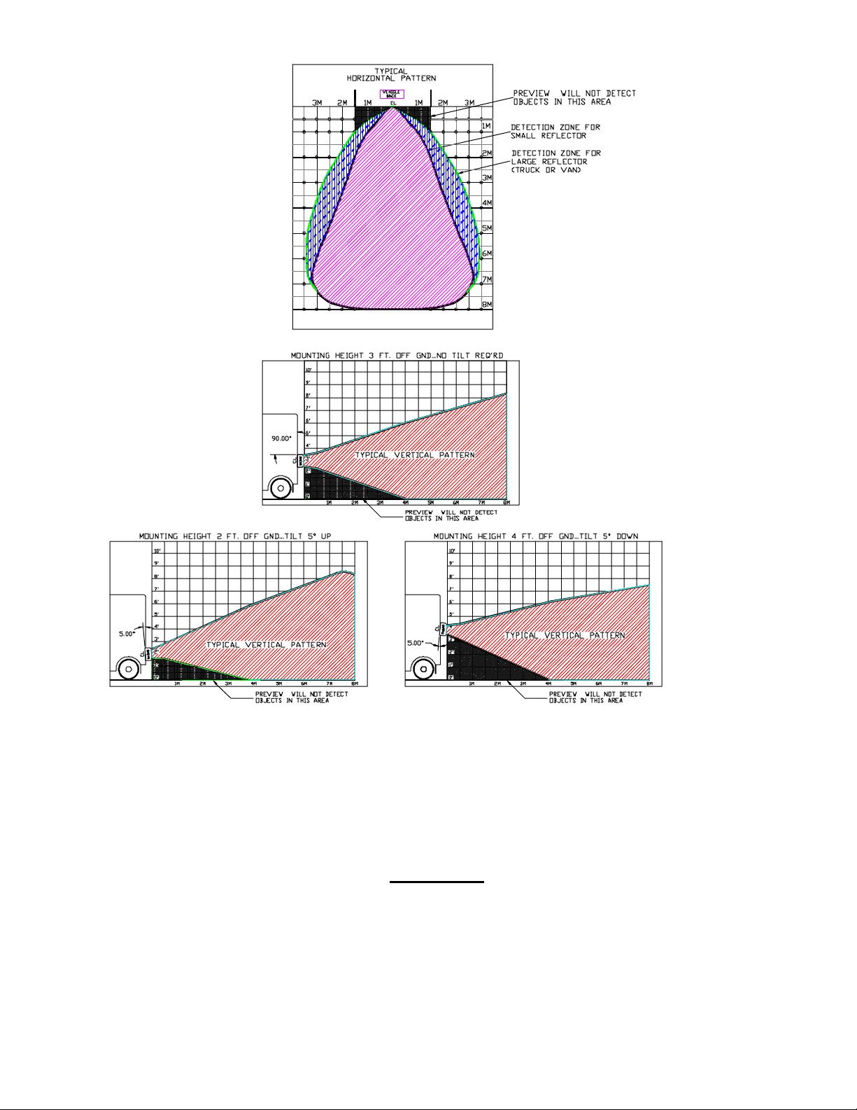
Figure 1: Typical horizontal and vertical patterns
WARNING
DUE TO THE PREVIEW OBJECT DETECTION SYSTEM’S SENSOR PATTERN, SOME OBJECTS
IN CERT AIN AREAS BE HIND THE V E HICLE MAY NOT BE DE TECTE D. IN ADDITION, ANY
OBJECTS BEHIND THE V E HICLE S WHEELS OR UNDER T HE BUMP E R WILL NOT BE
DETECTED.
Preco Electronics, Inc.
415 N. Maple Grove, Boise, ID 83704 * (800) 453-1141 Copyright 2000 Page 5 of 10
370-851-1B

Installation Instructions
Locate the PreView sensor unit so it will operate properly under all conditions. The PreView system is very sensitive to mounting
location and orientation. The sensor should be mounted in the rear center of the vehicle, perpendicular to the ground at a height of 3
feet (1meter). If this is not feasible, heights between 2 and 4 feet (0.6 and 1.2 meters) are allowed by mounting the radar sensor plus
or minus 5 degrees from vertical (see Figure 1).
The PreView sensor should be mounted 90 degrees from the vertical plane when at a 3-foot (1-meter) height. Adjustments to this
angle are required at mounting heights between 2 and 4 feet (0.6 and 1.2 meters). Mounting at a height of 2 feet (0.6 meter) requires
the PreView sensor to be pointed up at an angle of 5 degrees, and at a height of 4 feet (1.2 meters) the unit should be tilted down 5
degrees. This is very important, and if not followed the PreView system unit may either constantly detect the ground (pointed down) or
not detect small objects close to the ground (pointed up).
The PreView sensor should ideally be mounted in the rear center of the vehicle. In many applications this is not physically possible.
To compensate for this fact, the sensor should be angled in 2.5-degree increments to the left or right. T his adjustment in mounting
angle will affect the detection pattern, and the end user shall be responsible for verifying the pattern conforms to their requirements. If
PreView sensor is approximately .5 meters (19.7 inches) off center of the vehicle, left or right, then the sensor should be tilted towards
center by 2.5-degrees. If PreView sensor is approximately 1.0 meters (39.4 inches) off center of the vehicle, left or right, then the
sensor should be tilted towards center by 5 degrees.
The PreView sensor should be mounted flush with the rear of the vehicle, but it may be allowed to be recessed if there are no
obstructions to the left or right of the sensor. The depth of this recess is dependent on the distance from the sensor to any side, upper,
or lower obstruction. If the sensor unit is mounted in a recessed fashion and there is an obstruction, it may continuously detect this
obstruction and not operate correctly.
1. Since the PreView system is designed to detect some objects in a major portion of the operator blind zone where operator view is
obscured. The PreView sensor must be mounted centered on the vehicle’s rear at 36” (1M) +/- 12” (0.3M) above ground level
with the mounting plate vertical and the sensor facing to the rear of the vehicle.
2. Select a mounting location at the rear of the vehicle that will provide protection from impact, debris and adverse weather
conditions while allowing unobstructed projection to the target hazard area.
3. Using the back plate as a template, scribe position marks through the mounting holes in the unit. Drill 9/32” (7mm) holes at the
position marks.
4. Secure the unit on the vehicle with four user-supplied 1/4" (6.5mm) bolts and locknuts, or equivalent.
5. Use 18 gage (minimum) wire and a fuse (not supplied) to electrically connect power to the PreView sensor as shown in the System
Connection Diagram, Figure 2. The power connection to the PreView system is made using the 2-wire cable. The positive power
connection (red) should be made to the ignition switch accessory terminal so the vehicle’s battery is not unintentionally drained.
The power ground (black) connection should be made to a good battery ground connection. All connections should be made with
waterproof splices (not supplied).
6. The 3-wire cable is used to connect to the vehicle’s reverse indication and an optional back up alarm. If the vehicle reverse
indication is a positive signal (+12/24V when in reverse, ground otherwise), connect the white wire directly to this indication wire.
A good source for this connection is the vehicle’s reverse lights. If switching a ground connection makes the reverse indication,
then an external relay is required to supply a positive signal to the PreView system. See the wiring diagram for further information.
7. The back up alarm connection is made by connecting the red wire of the 3-wire cable to the positive input on the alarm and the
black wire to the negative input of the alarm. DO NOT CONNECT T HE BACK-UP ALARM NEGATIVE (BLACK) CONNECT ION
TO VEHICLE GROUND. IF EXISTING BACKUP ALARM NEGATIVE CONNECTION IS MADE TO CHASSIS GROUND,
DISCONNECT FROM CHASSIS GROUND PRIOR TO POWER APPLICATION.
8. Route the display unit cable in accordance with the vehicle manufacturer’s recommendations for the cab. Make sure to route
where the cable will be protected from debris and damage. Secure the cable, allowing a 3” service loop at both ends.
9. Mount the operator display unit prominently in the operator’s view so that the operator can monitor one of his rearview mirrors and
display unit at the same time. Connect the pre-routed cable to the display unit and the sensor.
The PreView system is sensitive to polarity and will not operate when power is connected backwards.
Technical support can be obtained by calling 1-800-453-1141 between 7:00 AM and 5:00 PM MST.
Preco Electronics, Inc.
NOTE
415 N. Maple Grove, Boise, ID 83704 * (800) 453-1141 Copyright 2000 Page 6 of 10
370-851-1B

Figure 2: System Connection Diagram
Preco Electronics, Inc.
415 N. Maple Grove, Boise, ID 83704 * (800) 453-1141 Copyright 2000 Page 7 of 10
370-851-1B

M ANUFACTURER LIMITE D WARRANTY AND
LIMITATION OF LIABILITY
Manufacturer warrants that on the Date of Purchase this Product will conform to
Manufacturer's published specifications for the product, which are available from Manufacturer on
request, and Manufacturer warrants that the product is free from defects in materials and
workmanship. This Limited Warranty extends for twelve (12) months from the date of manufacture.
Manufacturer will, at its option, repair or replace any product found by Manufacturer to be defective
and subject to this Limited Warranty.
This Limited Warranty does not apply to parts or products that are misused; abused;
mod ified; d am aged b y ac c ident, fir e or oth er hazar d; im properly inst alled or operated ; or not
maintained in accordance with the maintenance procedures set forth in Manufacturer's Installation
and Operating Instructions.
To obtain warranty service, you must ship the product(s) to the specified Manufacturer
location within thirty (30) days from expiration of the warranty period. You must fill out the warranty
claim form and include the form with the product. You must prepay shipping charges and use the
original shipping container or equivalent. Return shipping charges within the United States,
Canada, and Puerto Rico will be paid by Manufacturer. This Limited Warranty will apply only to a
pr odu c t p urc hased and located in t he United States , Canada, or P uerto Rico.
EXCLUSIO N OF OTHER WARRANTIES
EXPRESSED, IMPLIED OR STATUTORY . THE IMPLIED WARRANTIES FOR MERCHANTABILITY AND
FITNESS FOR A PARTICULAR PURPOSE ARE HEREBY EXCLUDED AND SHALL NOT APPL Y TO THE
PRODUCT. BUYER'S SOLE AND EXCLUSIVE REMEDY IN CONTRACT, TORT OR UNDER ANY OTHER
THEORY AG AINST MANUFACTURER RESPECTING THE PRODUCT AND ITS USE SHALL BE THE
REPLACEMENT OR REPAIR OF THE PRODUCT AS DESCRIBED ABOVE.
LIMITATION OF L IABILI TY:
LIMITED WARRANTY OR ANY OTHER CLAIM RELATED TO MANUFACTURER'S PRODUCTS,
MANUFACTURER'S LIABILITY FOR DAMAGES SHALL BE LIMITED TO THE AMOUNT PAID FOR THE
PRODUCT AT THE TIME OF ORIGINAL PURCHASE. IN NO EVENT SHALL MANUFACTURER BE
LIABLE FOR LOST PROF ITS, THE COST OF SUBSTITUTE EQUIPMENT OR LABOR, PROPERTY
DAMAGE, OR OTHER SPECIAL, CONSEQUENTIAL OR INCIDENTAL D AMAG ES BASED UPON ANY
CLAIM FOR BREACH OF CONTRAC T, NEGLIGENCE OR OTHER CLAIM, EVEN IF MANUFACTURER OR
A MANUFACTURER'S REPRESENTATIVE HAS BEEN AD VISED OF THE POSSIBILITY OF SUCH
DAMAGES
. Manufacturer shall have no further obligation or liability with respect to the product or
IN THE EVENT OF LIABI LITY FOR DAMAGES ARISING OU T OF THIS
: MANUFACTURER MAKES NO OTHER WARRAN TIES,
its s ale, operation and u s e, an d Manuf ac turer n eith er as s umes nor aut horiz es th e as s umpt ion of
any other obligation or liability in connection with such product.
This Limited Warranty gives you specific legal rights, and you may also have other legal
rig hts, which vary, from s tate to st ate. S om e s tates do not allow the exclusion or limitation of
incidental or consequential damages, so the above exclusion or limitation may not apply to you.
Any oral statement s or repr es ent ation s about th e product, wh ic h may have been made by
salesmen or Manufacturer representatives, do not constitute warranties. This Limited Warranty may
not be am ended , modified or enlarged, except b y a wr itten agreement s igned by an au th or iz ed
official of Manufacturer which expressly refers to this Limited Warranty.
Preco Electronics, Inc.
415 N. Maple Grove, Boise, ID 83704 * (800) 453-1141 Copyright 2000 Page 8 of 10
370-851-1B

PREVIEW DAILY MAINTAINANCE
Detach this page and place with daily operator maintenance procedures
Safety Message to Operators of Vehicles with PreView Systems
1. The PreView system is intended as an Object Detection System and should not be relied upon as your first line of defense for the
safe operation of the vehicle. It should be used in conjunction with established safety programs and procedures to augment the
safe operation of the vehicle, ground personnel, and adjacent property. Should the system become inoperative, it could jeopardize
the safety or lives of those who depend on the system for safety.
2. Testing and inspection of the system in accordance with these instructions and record of the results should be listed on the daily
maintenance report. The units on operating vehicles must be tested each day prior to the vehicle's operation. Results of this test
must be recorded in the maintenance log.
3. People operating this equipment
4. People's lives depend on the proper installation of this product in conformance with these instructions. It is necessary to read,
understand and follow all instructions shipped with the product.
5. Failure to follow all safety precautions and instructions may result in property damage, serious injury, or death.
6. The PreView Object Detection System is intended for commercial use. Proper installation of a back-up aid requires a good
understanding of truck electrical systems and procedures, along with proficiency in the installation.
7. When drilling into a vehicle structure, be sure that both sides of the surface are clear of anything that could be damaged.
8. Store these instructions in a safe place and refer to them when maintaining and/or reinstalling the product.
Testing and Maintenance
NOTE: A walk around test shall be performed every day to verify proper function of the system and to familiarize the operator with the
zone of detection. More frequent inspections should be performed when:
1.1 The vehicle is operating in a particularly dirty or harsh environment.
1.2 The operator has reason to suspect the system has been damaged.
This test should be performed with two people, one who remains in the cab (the operator), and one who walks through the sensor field
to the rear of the vehicle (the assistant). If two people are not available, the operator can verify the operation of the system and
attached back-up alarm singly via the audible indicator.
check for proper operation at the beginning of every shift or safety inspection period.
MUST
1. Clean the black sensor surface of any accumulation of dirt, mud, snow, ice, or debris.
2. Visually inspect the attached wiring and cable and verify that they are properly secured, not chafing or dangling free where they
could become snagged and damaged. Inspect the Radar Sensor and Operator Display Module and verify that they are securely
attached to the vehicle.
3. Start the vehicle, place the vehicle in neutral or park, and set the park brakes.
4. Verify the green “POWER” light is illuminated on the in-cab annunciator.
5. Press the “TEST” button on the in-cab display unit. The green “POWER” light will continuously blink signifying that the system is
now in the operator walk around test mode for 15 minutes, or until the walk around is completed. The area to the rear of the
vehicle should be clear of obstacles for a distance of 8 meters. If the display shows any indicator other than the green light then
there are objects to the rear of the vehicle that will interfere with the test. Move the vehicle to a clear area and proceed.
6. The assistant should move to the rear of the vehicle and to the side so that he is in sight of the operator's mirrors. He should
begin ½ meter (20”) to the rear of the rearmost part of the vehicle. As the assistant walks towards the centerline of the vehicle
parallel to the rear, the external backup alarm will activate, signifying the sensor has detected him. Upon hearing the backup alarm
the operator should verify all the display LEDs are lit and the audible alarm is quickly pulsing. Note: If an external backup alarm is
not connected, the operator will notice a detection only by the display LEDs and buzzer operation and communicate the detection
or lack of detection to the assistant as the assistant moves through the area to the rear of the vehicle.
7. The assistant should continue walking through the area at the rear of the vehicle noting the area that detection occurs.
8. Now walk from the center of the rear of the vehicle straight back, away from the vehicle. When the alarm quits sounding the
detection limit (8 Meters) has been reached.
9. Move halfway back and remain still for a few seconds, the alarm should continue to sound, demonstrating the system’s ability to
detect a still object.
10. The assistant should walk the complete rear of the vehicle noting the detection edges of the entire coverage area.
11. After the test the assistant needs to communicate to the operator the details on where detection started and stopped to the rear of
the vehicle.
12. The mode can be reset from test to normal operation upon test completion after 15 minutes or by placing the vehicle in reverse.
For Questions call 1-800-453-1141 between 7:00 AM and 5:00 PM Mountain Standard Time
Preco Electronics, Inc.
415 N. Maple Grove, Boise, ID 83704 * (800) 453-1141 Copyright 2000 Page 9 of 10
370-851-1B
Detach this page and place with daily operator maintenance procedures
PreView typical horizontal and vertical patterns
WARNING
DUE TO THE PREVIEW OBJECT DETECTION SYSTEM’S SENSOR PATTERN, SOME OBJECTS
IN CERT AIN AREAS BE HIND THE V E HICLE MAY NOT BE DE TECTE D. IN ADDITION, ANY
OBJECTS BEHIND THE V E HICLE S WHEELS OR UNDER T HE BUMP E R WILL NOT BE
DETECTED.
Preco Electronics, Inc.
415 N. Maple Grove, Boise, ID 83704 * (800) 453-1141 Copyright 2000 Page 10 of 10
370-851-1B
 Loading...