

Page 1
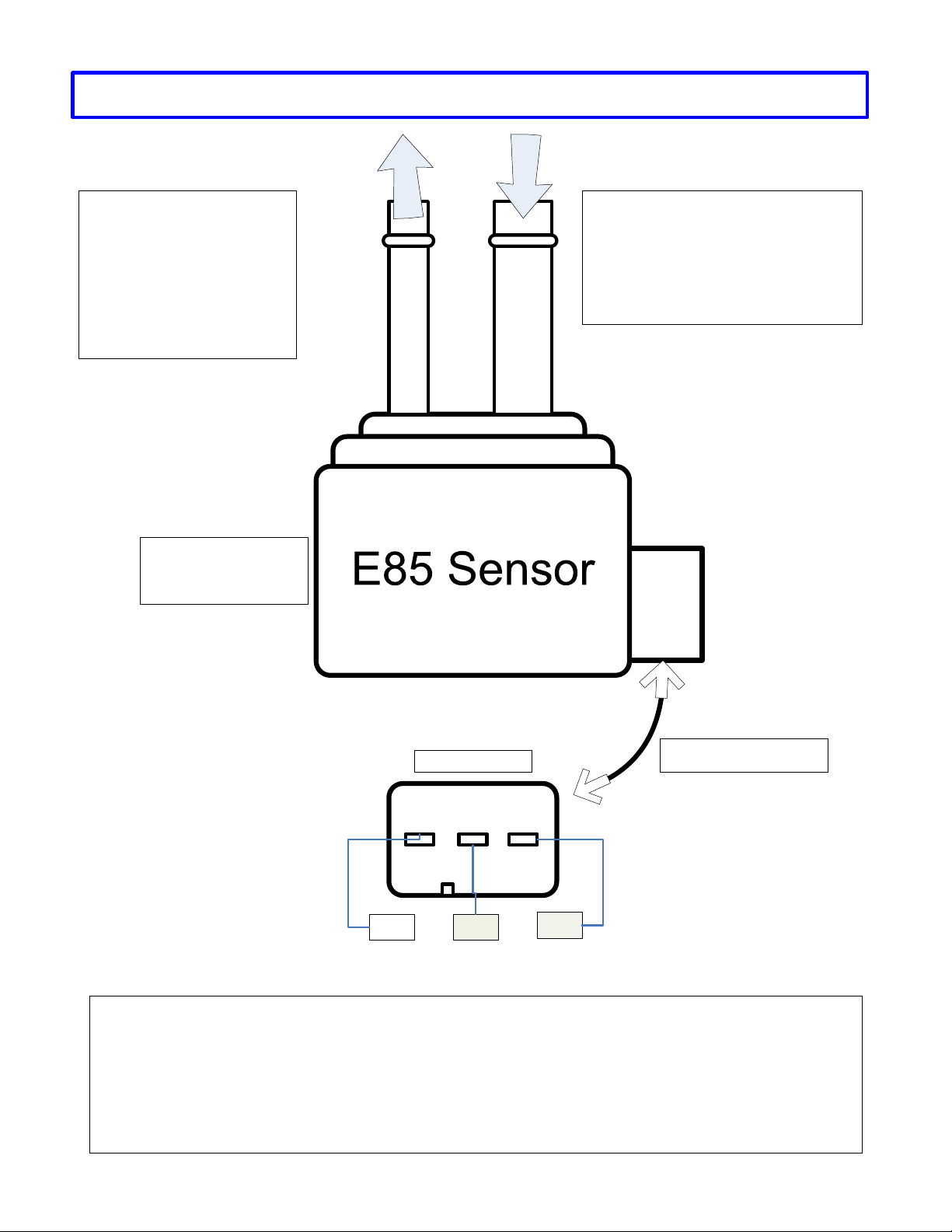
Swagelok 6AN fittings are
recommended to connect the
return lines to the sensor in
and out tubes. One (1)
reducer and two (2) unions
are needed.
- Reducer P/N: SS-500-R-6
- Union P/N: SS-600-6-6AN
BigStuff3 E85 Sensor Wiring Diagram
t
u
O
l
e
u
F
To Fuel Tank
n
I
l
e
u
F
Install the sensor in the fuel system
return line to the fuel tank. The return
fuel needs to run through the sensor.
Connect the return line from the
engine to the larger of the two sensor
tubes.
From Engine
This sensor is found
in most GM flex-fuel
vehicles
Top of Connector
Ground 12V
Electrical Connector
Signal
Electrical Connections – For the Signal and Ground wires:
- Systems using a three (3) wire Hall Effect Device (HED) crank sensor, use header connector 2, pin W1 for
the signal wire and W3 for the sensor ground wire.
- For traditional IPU applications and the Ford Mod motor system, use header connector 1, pin E3 for the
signal wire and J2 for the sensor ground wire.
 Loading...