

Precision Trading 60 R3.0 User Manual

Operator Manual, Supercharger 60 R3.0
TABLE OF CONTENTS
1. INTRODUCTION AND SYSTEM DESCRIPTION .................................................................. 5
2. CONDENSED OPERATING INSTRUCTIONS ....................................................................... 8
2.1 Constant Current Charge (normal mode) ............................................................................................... 8
2.2 Constant Voltage ........................................................................................................................................ 9
2.3 Peak Voltage Charge ............................................................................................................................... 10
2.4 Discharge .................................................................................................................................................. 11
3. SPECIFICATIONS ................................................................................................................ 12
3.1 CHARGE .................................................................................................................................................. 12
3.2 DISCHARGE ........................................................................................................................................... 14
3.3 TIMER ...................................................................................................................................................... 15
3.4 LINE INPUT VOLTAGE: ...................................................................................................................... 16
3.5 DIGITAL PANEL METERS .................................................................................................................. 17
3.6 FUSES and BREAKERS (Other than charge and discharge current limiters) ................................. 17
4. CONTROLS AND DISPLAYS .............................................................................................. 18
4.1 M1 - Ammeter .......................................................................................................................................... 18
4.2 M1 - Voltmeter ......................................................................................................................................... 18
4.3 R1 - Main Charge Current Selector ....................................................................................................... 18
4.4 R2 - Topping/Discharge Current Selector ............................................................................................. 18
4.5 SW1 - Main Time selector switch ........................................................................................................... 18
4.6 SW2 - Total Time selector switch ........................................................................................................... 18
4.7 SW3 – Keypad .......................................................................................................................................... 18
4.8 SW4 - CELL SELECTOR: ..................................................................................................................... 19
4.9 SW5 - DIGITAL VOLTMETER INPUT SELECTOR: ...................................................................... 19
4.10 SW6 - VOLTAGE MODE SELECTOR:............................................................................................... 19
4.11 SW7 - TIMER SPEED SELECTOR: .................................................................................................... 19
4.12 DS1A - RESET:........................................................................................................................................ 21
4.13 DS1B - CYC END: ................................................................................................................................... 21
4.14 DS2A - DUAL: ......................................................................................................................................... 21
4.15 DS2B - MAIN: .......................................................................................................................................... 21
4.16 DS3A - SINGLE: ...................................................................................................................................... 21
4.17 DS3B - TOP: ............................................................................................................................................. 21
4.18 DS4A - AUTO: ......................................................................................................................................... 21
4.19 DS4B - DISCH: ........................................................................................................................................ 21
Page 1 of 62

Operator Manual, Supercharger 60 R3.0
4.20 DS5A - FULL: .......................................................................................................................................... 21
4.21 DS5B - DISCH: ........................................................................................................................................ 21
4.22 DS6A - CAP FAIL: .................................................................................................................................. 21
4.23 DS6B - OPEN LIM: ................................................................................................................................. 21
4.24 DS7A - OVR TEMP: ............................................................................................................................... 21
4.25 DS7B - OVR HEAT: ................................................................................................................................ 22
4.26 DS8A - VOLT FLT: ................................................................................................................................. 22
4.27 DS8B -CURR FLT: .................................................................................................................................. 22
4.28 DS9 - CC ................................................................................................................................................... 22
4.29 DS10 - CV ................................................................................................................................................. 22
4.30 DS11 - PEAK ............................................................................................................................................ 22
4.31 AUDIBLE ALARM: ................................................................................................................................ 22
5. MODES OF OPERATION ..................................................................................................... 23
5.1 CONSTANT CURRENT CHARGE ...................................................................................................... 23
5.2 CONSTANT VOLTAGE CHARGE. ..................................................................................................... 24
5.3 PEAK CHARGE. ..................................................................................................................................... 25
5.4 DISCHARGE. .......................................................................................................................................... 26
6. OPERATING INSTRUCTIONS ............................................................................................. 27
6.1 GENERAL ............................................................................................................................................... 27
6.2 CONSTANT CURRENT CHARGE. ..................................................................................................... 28
6.3 CONSTANT VOLTAGE CHARGE ...................................................................................................... 28
6.4 PEAK VOLTAGE CHARGE: ............................................................................................................... 29
6.5 DISCHARGE ........................................................................................................................................... 30
6.6 Float/Peak Voltage Chart ........................................................................................................................ 31
6.7 OPERATING NOTES AND PRECAUTIONS ..................................................................................... 32
7. INSTALLATION .................................................................................................................... 33
7.1 BENCH SPACE. ...................................................................................................................................... 33
7.2 LINE VOLTAGE. .................................................................................................................................... 33
8. VERIFICATION OF PERFORMANCE .................................................................................. 35
8.1 REQUIRED TEST EQUIPMENT AND ACCESSORIES................................................................... 35
8.2 VISUAL VERIFICATION. .................................................................................................................... 35
8.3 TIMER VERIFICATION. ...................................................................................................................... 36
8.4 BATTERY OVERTEMP CUT-OFF. .................................................................................................... 37
8.5 VOLTAGE FAULT TEST. ..................................................................................................................... 37
8.6 REVERSE POLARITY TEST. .............................................................................................................. 38
8.7 OVERVOLTAGE CUT-OFF. ................................................................................................................ 38
Page 2 of 62

Operator Manual, Supercharger 60 R3.0
8.8 DISCHARGE VOLTAGE CUT-OFF. ................................................................................................... 38
8.9 FULL DISCHARGE. .............................................................................................................................. 39
8.10 CURRENT TRACKING. ........................................................................................................................ 39
8.11 VOLTAGE CONTROL. ......................................................................................................................... 39
8.12 FLOAT VOLTAGE: ............................................................................................................................... 40
8.13 PEAK VOLTAGE: .................................................................................................................................. 40
8.14 METERS .................................................................................................................................................. 41
9. CALIBRATION ..................................................................................................................... 42
9.1 CIRCUIT BOARD ADJUSTMENTS AND CALIBRATION ............................................................. 42
9.2 DIGITAL METERS (see [Figure 6]). ..................................................................................................... 42
10. TROUBLESHOOTING AND REPAIRS ................................................................................ 53
10.1 TROUBLESHOOTING .......................................................................................................................... 53
10.2 FINDING A SHORTED DISCHARGE TRANSISTOR ...................................................................... 55
11. REPLACEABLE MODULES AND PARTS .......................................................................... 59
11.1 CIRCUIT BOARDS ................................................................................................................................ 59
11.2 PARTS ...................................................................................................................................................... 59
11.3 OTHER ..................................................................................................................................................... 59
12. BATTERY TESTING NOTES ............................................................................................... 60
13. DISCLAIMER ........................................................................................................................ 61
14. REVISION INDEX ................................................................................................................. 62
Page 3 of 62

Operator Manual, Supercharger 60 R3.0
TABLE OF FIGURES
Figure 1 - Block Diagram ...................................................................................................................................... 7
Figure 2 - Front Panel .......................................................................................................................................... 20
Figure 3 - Line Voltage Wiring, 115V ................................................................................................................ 33
Figure 4 - Line Voltage Wiring, 208/230V ......................................................................................................... 34
Figure 5 - Line Voltage Wiring, 230/245V ......................................................................................................... 34
Figure 6 - Meters Board Adjustments .................................................................................................................. 44
Figure 7 - Control Switch Board Adjustments .................................................................................................... 45
Figure 8 - Current Control Board Adjustments ................................................................................................... 47
Figure 9 - Monitor Board Adjustments ................................................................................................................ 48
Figure 10 - Voltage Control Board Adjustments ................................................................................................. 50
Figure 11 - Circuit Board Sequence .................................................................................................................... 52
Figure 12 - Measuring for a shorted transistor ..................................................................................................... 56
Figure 13 - Location of Current Limiters ............................................................................................................ 57
Figure 14 - Power Block Diagram ....................................................................................................................... 58
TABLE OF TABLES
Table 1 - Constant Voltage and Peak Voltage Chart ........................................................................................... 31
Table 2 - Index of Revisions ................................................................................................................................ 62
Page 4 of 62

Operator Manual, Supercharger 60 R3.0
1. INTRODUCTION AND SYSTEM DESCRIPTION
Congratulations! You now own the finest battery Charger-Analyzer available today. The
Supercharger is a precision instrument designed to charge and analyze NICKEL-CADMIUM,
LEAD-ACID and other rechargeable batteries exactly as recommended by the battery
manufacturers.
The simple to set controls plus the condensed operating procedure found on the front panel
makes the Supercharger a very easy to operate CHARGER/ANALYZER, which combined with
easy to read CURRENT, VOLTAGE, TIME and STATUS indicators, makes it also a very
simple unit to monitor.
The Supercharger is also designed for speed, for it can charge two batteries, (actually, any
number of batteries where the total number of cells is 50 or less), at maximum currents, and it
can also discharge two batteries at reduced currents, or one battery (25 cells or less) at
maximum cu r rent.
The Supercharger also provides a Voltage Control enhancement that allows the ChargerAnalyzer, originally designed for Constant Current operation on Nickel-Cadmium batteries to
also be able to handle Lead-Acid and other type of rechargeable batteries, where the end
voltage is a more reliable indicator of the state of charge (as opposed to Nickel-Cadmium
batteries).
Dependability is another great plus of the Supercharger. 100% SOLID STATE circuitry
requires no scheduled maintenance. No relay contacts to inspect and clean. No high current
carrying contacts to arc and burn. A simple performance verification procedure is all it takes to
determine if the instrument requires re-calibration or repair.
This instrument is also protected against certain internal performance deviations and
programming errors, plus it is also designed to sense certain battery abnormalities to protect the
instrument and battery from possible damage. In the event that any malfunction takes place,
VISUAL and AUDIBLE indicators will turn on, alerting the operator and preventing any
further operation of the unit.
The Supercharger Battery Charger-Analyzer System is comprised of the Charger-Analyzer, the
Temp-plate, the Battery Cable and several accessories.
The Charger-Analyzer is basically a precision programmable constant current source (for
charge) and a programmable constant current sink (for discharge) combined with voltage and
temperature sensing circuits for total battery monitoring.
The specially designed circuitry provides a performance not achieved by any of the older
conventional battery charging methods. The Supercharger will deliver current into a short
circuit or a battery or combination of batteries totaling 50 cells, within ±1% of the programmed
value, independent of line voltage variations (within ±10% of the nominal line voltage).
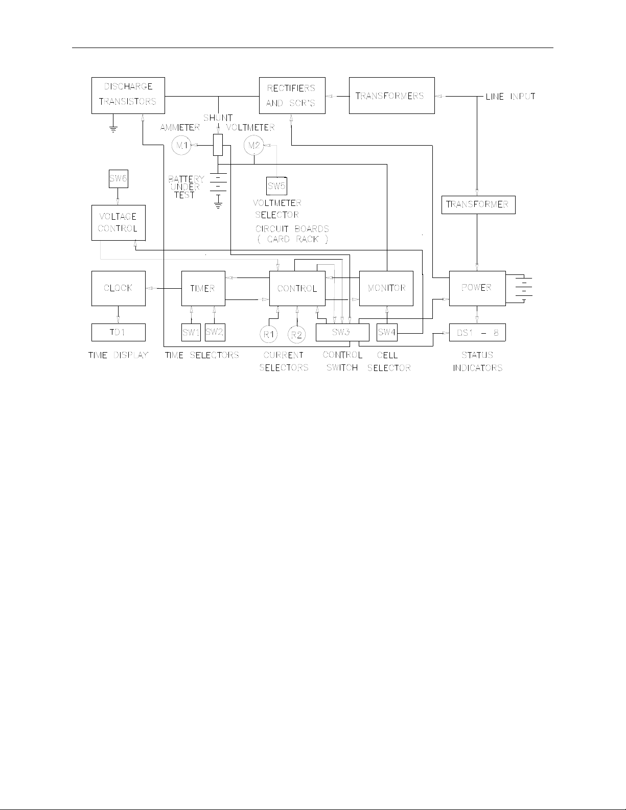
The control circuitry of the Charger-Analyzer consists of a CONTROL SWITCH, a CLOCK, a
TIMER, a CURRENT CONTROL, a SYSTEM MONITOR, a POWER REGULATOR and a
VOLTAGE CONTROL CIRCUIT. See
The CONTROL SWITCH receives the function commands from the function selector switch
on the front panel and outputs control signals to the rest of the circuit boards as well as to the
charge SCR'S and discharge transistors.
Figure 1
Page 5 of 62

Operator Manual, Supercharger 60 R3.0
The TIMER provides all the required timing functions related to the charge and discharge
durations. Digital time and speed selectors provide the external inputs, while the four digit
readout of the CLOCK provides the elapsed time display.
The CURRENT CONTROL interprets the programmed current values and controls the angle of
firing of two SCR's to maintain a constant current in accordance to the feedback received from
a precision shunt.
Display of current is provided by an independent Digital Ammeter that uses the same shunt
used by the CURRENT CONTROL circuit.
Inputs from the TIMER, the SYSTEM MONITOR and the CONTROL SWITCH, determine
the operating mode of the CURRENT CONTROL circuit.
The SYSTEM MONITOR provides several safeguarding functions. It compares the measured
current against the programmed value and if they differ by more than one ampere, operation is
halted and a current malfunction is indicated.
It measures the battery voltage and compares it with the programmed number of cells. From
there, it determines during charge if the total voltage exceeds the equivalent of 1.75 V per cell,
indicating an Overvoltage condition, or during discharge if the total voltage is below the
equivalent of 1 volt per cell, indicating the end of the discharge cycle.
It checks for polarity reversal at voltages as low as .25V, as well as an absolute Overvoltage at
85 volts, both generating a voltage malfunction indication that prevents any further operation of
the unit.
It measures the temperature of the discharge heat dissipators and signals an overheat
malfunction if the internal temperature exceeds 90
o
C, as it could be caused by a fan failure or
an installation with restricted air flow. It also monitors the temperature of the batteries being
charged (via the TEMP-PLATE) and terminates the charge, indicating battery Overtemp, in the
event of battery overheating that may lead to thermal runaway.
The POWER REGULATOR provides all regulated voltages and power amplification as
required by the various circuits.
The VOLTAGE CONTROL CIRCUIT provides the functions that regulate the charging current
in the Constant Voltage (float) mode and in the Peak Voltage mode, transfers from Main to
Topping charge on a voltage peak or ends charging on a voltage peak (new feature).
The DIGITAL VOLTMETER provides internal battery voltage readings with resolutions of
0.1V and 0.01V, while a selectable external position allows single cell measurements to a
resolution of 0.001V.
Additional protection is provided by a high speed current limiter for the discharge transistor
bank, a slow speed current limiter for the charge circuit and a magnetic circuit breaker capable
of tripping under fast high current overload conditions.
Page 6 of 62
Operator Manual, Supercharger 60 R3.0
Figure 1 - Block Diagram
Page 7 of 62

Operator Manual, Supercharger 60 R3.0
2. CONDENSED OPERATING INSTRUCTIONS
CAUTION: Disconnect power and batteries before performing any internal maintenance.
Failure to observe this caution may result in serious damage to the unit and injury to the
operator.
NOTE 1: Depress the RESET button before turning the power on, or before connecting or
disconnecting the battery.
NOTE 2: The current selector potentiometers display three digits indicating XX.X AMPS.
e.g.: in order to select 4A dial 040 (04.0A), and for 20A dial 200 (20.0A).
2.1 Constant Current Charge (normal mode)
2.1.1. Number of Cells
2.1.1.1. Enter the number of cells
2.1.1.2. NOTE: when charging more than one battery enter the total number of
cells.
2.1.2. Main Charge Time
2.1.2.1. Enter the MAIN CHARGE TIME and TOTAL TIME if in the TWO
RATE mode, or enter the TOTAL CHARGE TIME only if in the
SINGLE RATE mode.
2.1.2.2. Verify that the Timer Speed is consistent with the required elapsed
time (hours or minutes).
2.1.2.3. Enter the MAIN and TOPPING CHARGE CURRENTS, if in the
TWO RATE mode, or enter the TOPPING CURRENT only if in the
SINGLE RATE mode.
2.1.2.4. Place batteries on the TEMP-PLATE. When working with only one
battery, connect the free plug into the shorted receptacle provided in
the TEMP-PLATE. Verify also that the small cable is connected to the
TEMP-PLATE (the red "BATTERY OVERTEMP" INDICATOR will
be on if not connected).
2.1.2.5. Depress the CONTROL BUTTON corresponding to the desired mode
(white for TWO RATE and yellow for SINGLE RATE).
2.1.2.6. The charge will terminate automatically (CYCLE END) when the
TOTAL TIME selected is reached.
2.1.2.7. The charge will terminate as a FAULT if the MONITOR CIRCUIT
detects that:
• Battery temperature exceeds 45
o
C/113oF (BATTERY
OVERTEMP FAULT).
• Battery voltage exceeds the equivalent of 1.75V/cell (VOLTAGE
FAULT).
• The actual charge current deviates from the programmed value by
more than 1 AMP (CURRENT FAULT).
Page 8 of 62

Operator Manual, Supercharger 60 R3.0
2.2 Constant Voltage
2.2.1. Battery Voltage
2.2.1.1. Enter the nominal battery voltage using the cell selector (see chart on
page 19).
2.2.1.2. Program the charge (maximum) current in the Topping Current
selector.
2.2.1.3. Program sufficient time in the Total Time selector to allow the battery
to reach the required charge under constant voltage charge (consult
battery manufacturers specifications). Verify that the Timer Speed is
consistent with the required elapsed time.
2.2.1.4. Start the Charger-Analyzer in the Single Rate mode. The charger will
begin to reduce the charging current when the battery voltage is within
0.5V of the float level.
2.2.1.5. The charge will terminate automatically (CYCLE END) when the
TOTAL TIME selected is reached.
2.2.1.6. The charge will terminate as a FAULT if the MONITOR CIRCUIT
detects that:
• Battery temperature exceeds 45
OVERTEMP FAULT).
• The actual charge current deviates from the programmed value by
more than one AMP (CURRENT FAULT). Note: this will occur
only before the Charger-Analyzer switches from constant current
to constant voltage.
o
C/113oF (BATTERY
Page 9 of 62

Operator Manual, Supercharger 60 R3.0
2.3 Peak Voltage Charge
2.3.1. Nominal Battery Voltage
2.3.1.1. Enter the nominal battery voltage using the cell selector (see chart on
page xxx).
2.3.1.2. Select transfer from Main to Topping on Peak or stop on Peak.
2.3.1.3. Program the Main and Topping Charge currents as required.
2.3.1.4. Program the Main and Total Time selectors to allow the battery to
reach the required charge level (consult battery manufacturers
specifications). Verify that the Timer Speed is consistent with the
required elapsed time.
2.3.1.5. Start the Charger-Analyzer in the Dual Rate mode. The charger will
transfer from Main to Topping charge when the battery reaches the
peak voltage or Start in the Dual or Single Rate mode and the ChargerAnalyzer will stop on peak (at any part of the cycle).
2.3.1.6. The charge will terminate automatically (CYCLE END) when the
TOTAL TIME selected is reached.
2.3.1.7. The charge will terminate as a FAULT if the MONITOR CIRCUIT
detects that:
o
• Battery temperature exceeds 45
C/113oF (BATTERY
OVERTEMP FAULT).
• The actual charge current deviates from the programmed value by
more than one AMP (CURRENT FAULT).
Page 10 of 62

Operator Manual, Supercharger 60 R3.0
2.4 Discharge
NOTE 1: Do not place batteries on the Temp-Plate during discharge. Due to the normal
heating of the battery a false Overtemp may be generated later during the charge
process.
NOTE 2: Do not attempt to discharge with the voltage mode selector in the Float or Peak
voltage modes. Voltage and current faults will occur depending on the battery voltage
and the cell selector setting.
2.4.1. Number of Cells
2.4.1.1. Enter the number of cells.
2.4.1.2. Ignore this step if FULL DISCHARGE is to be selected.
2.4.2. Total Time
2.4.2.1. Enter the TOTAL TIME.
2.4.2.2. Verify that the Timer Speed is consistent with the required elapsed
time.
2.4.2.3. Enter the DISCHARGE CURRENT.
2.4.2.4. Depress the Blue button for DISCHARGE with automatic cut-off
(ANALYSIS), or the RED button for FULL DISCHARGE (DEEP
CYCLE).
2.4.2.5. DISCHARGE will terminate automatically (CYCLE END) when the
(TOTAL) time selected is reached or (CAPACITY FAILURE) if the
BATTERY voltage reaches the equivalent of ONE VOLT per CELL
prior to the selected time.
2.4.2.6. NOTE: Battery voltage is ignored during Full Discharge.
2.4.2.7. Discharge will terminate as a FAULT if the MONITOR CIRCUIT
detects:
• An overheating of the discharge transistors (OVERHEAT
FAULT).
• That the discharge current differs from the programmed value by
more than one AMP (CURRENT FAULT).
• That the programmed current exceeds 30A for a battery voltage in
excess of 32V.
Page 11 of 62

Operator Manual, Supercharger 60 R3.0
3. SPECIFICATIONS
3.1 CHARGE
3.1.1. CONTROL: SCR, air cooled.
3.1.2. MAXIMUM CURRENT: 50 AMPS.
3.1.3. MINIMUM INCREMENT: 0.1 AMP.
3.1.4. ACCURACY and STABILITY of settings: ±1% of reading, ±0.1 AMP.
3.1.4.1. FLOAT:
• The reference voltage is set at the equivalent of 2.33V/cell (Lead-
Acid).
• The Cell Selector provides the basic reference as nominal battery
voltage, e.g.: a 24V battery is entered as 24 on the Cell Selector.
• Current reduction from within 0.5V of the float voltage, with an
accuracy of ±0.5%, ±0.1A
3.1.4.2. PEAK:
• The reference voltage is set at the equivalent of 2.45V/cell (Lead-
Acid).
• The Cell Selector provides the basic reference as nominal battery
voltage, e.g.: a 24V battery is entered as 24 on the Cell Selector.
• Voltage transfer or stop within " 1% of the Peak Voltage.
• Note: Due to cable/connector losses the peak voltage registered by
the Charger-Analyzer will be higher than the actual battery voltage
(up to 0.2V depending on current).
Page 12 of 62

Operator Manual, Supercharger 60 R3.0
3.1.5. MODES:
3.1.5.1. Main and topping for Constant Current
3.1.5.2. Constant Voltage
3.1.5.3. Peak Voltage.
3.1.6. TIMER:
3.1.6.1. 1 to 9 hours for MAIN charge time and 1 to 60 hours for TOTAL time.
3.1.6.2. Time can also be programmed in minutes by selecting the FAST mode
in the TIMER SPEED selector switch (Front Panel).
3.1.6.3. NOTE 1: Topping charge time equals the total charge time minus the
main charge time (TOTAL = MAIN + TOP).
3.1.6.4. NOTE 2: Newer instruments may have a new version of the Timer
(Identified by an external Timer Speed Switch) that has a maximum of
79 (hours or minutes) in Total Time.
3.1.7. OVERTEMP PROTECTION:
3.1.7.1. Four thermistors on the TEMP-PLATE measure the battery
temperature.
3.1.7.2. The charge is terminated when the surface temperature of the TEMP-
PLATE reaches 39
o
C (102oF).
3.1.8. OVER/UNDER CURRENT PROTECTION:
3.1.8.1. A Monitor circuit continuously compares the actual charge current
with the programmed value.
3.1.8.2. Operation is terminated if they differ by more than 1 AMP.
3.1.9. OVERVOLTAGE PROTECTION:
3.1.9.1. Programmable, in accordance with the number of cells selected, at the
equivalent of 1.75 volts/cell (TOLERANCE: ±1%, ±0.1V).
3.1.9.2. Absolute maximum internal limit set at 85 VOLTS.
3.1.9.3. NOTE: Does not apply in the Float and Peak voltage modes. (Voltage
is controlled in those modes).
3.1.10. REVERSE POLARITY PROTECTION:
3.1.10.1. Operation of the unit is inhibited for reverse voltages greater than 0.5
VOLTS.
3.1.11. FUSING:
3.1.11.1. Aircraft type current limiter, ANL-60 (slow).
3.1.12. AC LINE CURRENT:
Page 13 of 62

Operator Manual, Supercharger 60 R3.0
3.1.12.1. 3 AMPS idling plus ½ the value of the charging current; e.g. when
charging 40 AMPS the line current is 23 AMPS (Note: nominal values,
line voltage and frequency dependent).
3.2 DISCHARGE
3.2.1. CONTROL: Transistors, air cooled.
3.2.2. MAXIMUM CURRENT:
3.2.2.1. 60 AMPS. Total power dissipation must not exceed 1.2KW (1200
watts, the product of battery voltage and battery current).
3.2.2.2. NOTE: Discharge current is automatically limited to 30 AMPS for
battery voltages in excess of 32 VOLTS. A current fault will be
generated if attempting to discharge at more than 30 AMPS.
3.2.3. MINIMUM INCREMENT:
3.2.3.1. 0.1 AMP.
3.2.4. ACCURACY and STABILITY of settings:
3.2.4.1. ±1% of reading, ±0.1AMP.
3.2.5. MODES:
3.2.5.1. Analysis (automatic cut-off)
3.2.5.2. Deep cycle (full discharge).
Page 14 of 62

Operator Manual, Supercharger 60 R3.0
3.2.6. TERMINAL VOLTAGE:
3.2.6.1. Programmable, in accordance with the number of cells selected, at the
equivalent of 1 VOLT/cell.
3.2.6.2. TOLERANCE: ±1% ±0.1 VOLT.
3.2.6.3. NOTE 1: Due to cable/connector losses the voltage registered by the
Charger-Analyzer will be lower than the actual battery voltage (up to
0.2V depending on current).
3.2.6.4. NOTE 2: Terminal voltage is ignored in the full discharge mode.
3.2.7. OVERHEAT PROTECTION:
3.2.7.1. Two thermistors measure the temperature of the bank of discharge
transistors.
3.2.7.2. Operation is terminated if the transistors surface temperature exceeds
90
o
C.
3.2.8. OVER/UNDER CURRENT PROTECTION:
3.2.8.1. A Monitor circuit continuously compares the actual discharge current
with the programmed value
3.2.8.2. Operation is terminated if they differ by more than 1 AMP.
3.2.8.3. NOTE: Undercurrent monitoring is disabled in the full discharge
mode for battery voltages below 2.5V.
3.2.9. REVERSE POLARITY PROTECTION:
3.2.9.1. Operation of the unit is inhibited for reverse voltages greater than 0.5V
3.2.10. FUSING:
3.2.10.1. Aircraft type current limiter, ANN-80(fast).
3.2.10.2. NOTE: The type of limiter and current rating are critical for proper
protection of the discharge circuits. Failure to replace the discharge
current limiter with the proper type/value may result in catastrophic
damage of the load banks.
3.3 TIMER
3.3.1. TIME BASE:
3.3.1.1. Microprocessor Controlled
3.3.2. MODES:
3.3.2.1. NORMAL: Timer advances at the rate of one count per minute
3.3.2.2. FAST: Timer advances at the rate of one count per second (MM:SS).
3.3.2.3. TEST: Timer advances at the rate of 60 counts per second (SS:SS/60).
(HH:MM).
Page 15 of 62

Operator Manual, Supercharger 60 R3.0
3.3.2.4. NOTE: The colon flashes at the rate of one cycle per second regardless
of the selected mode.
3.3.3. ACCURACY AND STABILITY:
3.3.3.1. ±0.01%
3.3.4. POWER FAILURE PROTECTION:
3.3.4.1. An internal rechargeable battery maintains (for several hours) the clock
and other vital circuits for a dependable resumption of operation after a
power failure.
3.3.4.2. The colon will be lit in case of a power failure.
3.3.4.3. NOTE: Do not operate the Charger-Analyzer without this battery or
with a battery in bad condition. Replace only with the same type, 7 or 8
cells (8.4V or 9.6V), rechargeable).
3.3.5. TIME LIMITS:
3.3.5.1. 0 to 9 in Main
3.3.5.2. 0 to 79 in Total
3.3.5.3. NOTE: The time limit in Total is dependent on the type of Timer.
Newer instruments, characterized by a Timer Speed Switch mounted
on the Front Panel have a limit of 79 (hours or minutes) while older
units have a limit of 60.
3.4 LINE INPUT VOLTAGE:
3.4.1. 115V(*), 208V, 230V, 245V
Note: For proper operation of this instrument, power line voltages must be
within ±10% of the nominal.
3.4.2. The instrument is normally wired for 230V operation.
3.4.3. A terminal block at the transformer inputs allows field re-wiring for 245V, 208V
or 115V operation. See figs 3, 4 and 5.
3.4.4. For operation at line voltages in excess of 220V at 50Hz, it is required that the
245V tap be used.
3.4.5. NOTE (*): Operation at 115V is not recommended at battery charging currents
above 15A due to the increased line current.
Page 16 of 62

Operator Manual, Supercharger 60 R3.0
3.5 DIGITAL PANEL METERS
3.5.1. VOLTMETER:
3.5.1.1. Accuracy (system): ±0.25% of reading, ±0.1V in the 200V scale,
±0.01V in the 20V scale, ±0.005V in the 2V scale.
3.5.1.2. Input impedance: 1 M-OHM.
3.5.1.3. Scale 2V, 20V and 200V (1.999V, 19.9V and 199.9V) for external
measurements and 20V and 200V for internal (battery) measurements.
3.5.2. AMMETER:
3.5.2.1. Accuracy (system): ±0.5% of reading, ±0.1A
3.5.2.2. Scale: 200A (199.9A)
3.5.3. SHUNT:
3.5.3.1. Accuracy: ±0.25%
3.5.3.2. Output: 1mV/A (100mV / 100A)
3.6 FUSES and BREAKERS (Other than charge and discharge current limiters)
3.6.1. Mains: Dual Magnetic Circuit Breaker
3.6.2. Electronics and digital panel meters: 1/4A SLO BLO.
Page 17 of 62

Operator Manual, Supercharger 60 R3.0
4. CONTROLS AND DISPLAYS
4.1 M1 - Ammeter
4.1.1. 0 to 199.9ADC DIGITAL PANEL METER.
4.1.2. Positive sign indicates charge current.
4.1.3. Minus sign indicates discharge current.
4.2 M1 - Voltmeter
4.2.1. 0 to 1.999VDC, 0 to 19.99VDC and 0 to 199.9VDC DIGITAL PANEL METER.
4.2.2. Indicates battery voltage in the internal (20/200V) position and voltage present at
the RED (+) and BLK (-) jacks in the 2/20/200V external positions. Positive sign
indicates proper battery connection. Minus sign indicates reversed polarity
connection.
4.3 R1 - Main Charge Current Selector
4.3.1. Ten turn potentiometer with digital readout to program: current
4.3.1.1. MAIN charge current, 0 to 50.0 AMPS.
4.4 R2 - Topping/Discharge Current Selector
4.4.1. Ten turn potentiometer with digital readout to program:
4.4.1.1. TOPPING charge current, 0 to 50.0 AMPS
4.4.1.2. DISCHARGE current, 0 to 60.0 AMPS
4.5 SW1 - Main Time selector switch
4.5.1. 0 to 9 hours (or minutes), to determine the duration of the main charge.
4.6 SW2 - Total Time selector switch
4.6.1. 0 to 60 hours (or minutes), to determine the total charge or discharge duration.
4.7 SW3 – Keypad
Five station membrane push button control switch to select and control the mode of
operation, as follows:
4.7.1. GREEN: Stop/reset, cycle end.
4.7.2. WHITE: Two rate charge mode (main and topping).
4.7.3. YELLOW: Single rate charge mode.
4.7.4. BLUE: Auto cut-off discharge (analysis).
4.7.5. RED: Full discharge (deep cycle).
Page 18 of 62

Operator Manual, Supercharger 60 R3.0
4.8 SW4 - CELL SELECTOR:
4.8.1. Two digit selector to program the battery terminal voltage as a function of the
number of cells.
4.8.2. Rate: 1.75 volts per cell for charge and 1.0 volts per cell for discharge.
4.8.3. Used also in the Float and Peak Voltage modes to enter nominal battery voltage.
4.9 SW5 - DIGITAL VOLTMETER INPUT SELECTOR:
4.9.1. External, 2/20/200V scale.
4.9.2. Internal, 20/200V scale.
4.10 SW6 - VOLTAGE MODE SELECTOR:
4.10.1. Four position switch to select Normal, Float and Peak Voltage modes.
4.11 SW7 - TIMER SPEED SELECTOR:
4.11.1. Three position switch to select
4.11.1.1. Normal (HH:MM)
4.11.1.2. FAST (MM:SS)
4.11.1.3. TEST (SS:S/60).
Page 19 of 62
 Loading...