

Page 1
LPG GAS ON DEMAND
WATER HEATER
Model
ShowerMate-550
11 Sunnybrook Drive
Cincinnati, OH. 45237
Phone: 513-641-4446 * 800-934-9690
Fax: 513-641-0733
www.precisiontemp.com
FOR YOUR SAFETY
WHAT TO DO IF YOU SMELL GAS
•
Extinguish any open flame.
•
Shut off the gas supply at the gas
container or source
•
Do not touch any electrical switch
or use any phone or radio in the
boat.
•
Do not start the boat’s engine or
electrical generator.
•
Contact the nearest gas supplier or
qualified service technician for
repairs.
•
If you can not reach a gas supplier
or qualified service technician,
contact the nearest fire department.
•
Do not turn on the gas supply until
the gas leak(s) has been repaired.
The Shower-Mate is a power vented automatic instantaneous water heater designed to be installed in
ventilated marine applications. This appliance must be installed in a ventilated compartment and in
compliance with any applicable Coast Guard and ABYC recommendations.
Every water heater is inspected and tested before it leaves the factory. In order for this unit to operate
safely and effectively, all installation instructions must be followed. Failure to comply with all installation
and operating instructions will void the warranty. PrecisionTemp, Inc. will not be responsible for anything
that is a result of non-compliance.
FOR YOUR SAFETY
DO NOT STORE OR USE GASOLINE
OR OTHER FLAMMABLE VAPORS AND
LIQUIDS IN THE VICINITY OF THIS OR
ANY OTHER APPLIANCE.
WARNING!
Improper installation, adjustment,
alteration, service or maintenance can
cause property damage, personal injury
or loss of life. Refer to the installation
instructions and/or operating instruct-ions
provided with this appliance. A qualified
installer service agency or the gas
supplier must perform installation and
service.
WARNING: If the information in these
instructions is not followed exactly, a fire
or explosion may result causing
property damage, personal injury or loss
of life.
Critical Installation Warnings
• All combustion air must be supplied from outside the
Boat, and all products of combustion must be vented to
outside the Boat.
• DO NOT vent water heater with venting system serving
another appliance.
• DO NOT modify water heater in any way.
• DO NOT alter water heater for a positive grounding
system.
• DO NOT HI-POT water heater unless electronic ignition
system (circuit board) has been disconnected.
• DO NOT use battery charger to supply power to water
heater even when testing.
Keep this book with the water heater at all times. It contains
inst r u c tions re g arding in stallat i o n , ope r a t i on an d
maintenance of your water heater. If you need further
information, contact your dealer, your nearest service center
or PrecisionTemp.
Rev. 3/15
Page 2
Please read these instructions thoroughly before starting your installation
Installation Instructions for the Shower-Mate Water Heater
The Shower-Mate water heater is designed to be installed in an area that is accessible for servicing and is well
ventilated. At least 20 square inches of incoming air is necessary and the power vent of the unit should always
be vented to the outside with 2” approved duct. NEVER install heater in such a manner that is not vented to
the outside. Doing so will void the warranty and cause the heater to malfunction and could result in serious
injury or death. Terminus of flue outside boat should be above the water line and not closable.
Selecting Installation Location
The water heater must not be installed in an area where the air intake can be covered and there is an opening
to the outside of at least 20 square inches to supply combustion air. It should be mounted so that the 2” duct
can be one continuous length to the outside of the boat and above the waterline. The water heater should be
located in an area where leakage will not result in damage to other items or the boat structure. Install the
heater as close to the gas supply as practical to minimize length of the gas line.
Although the ShowerMate can be mounted with zero clearance around the sides, top and bottom, be sure that
the installation does not interfere with any wiring, plumbing inside the boat. There should be ready access to
the front access cover for servicing and the fittings on the back and allow for the routing of the gas line into the
back of the case.
Mounting Unit
Unit should be located to allow hookups on the back and access to the front panel for servicing. Note
the locations of the bottom combustion air opening and mounting holes.
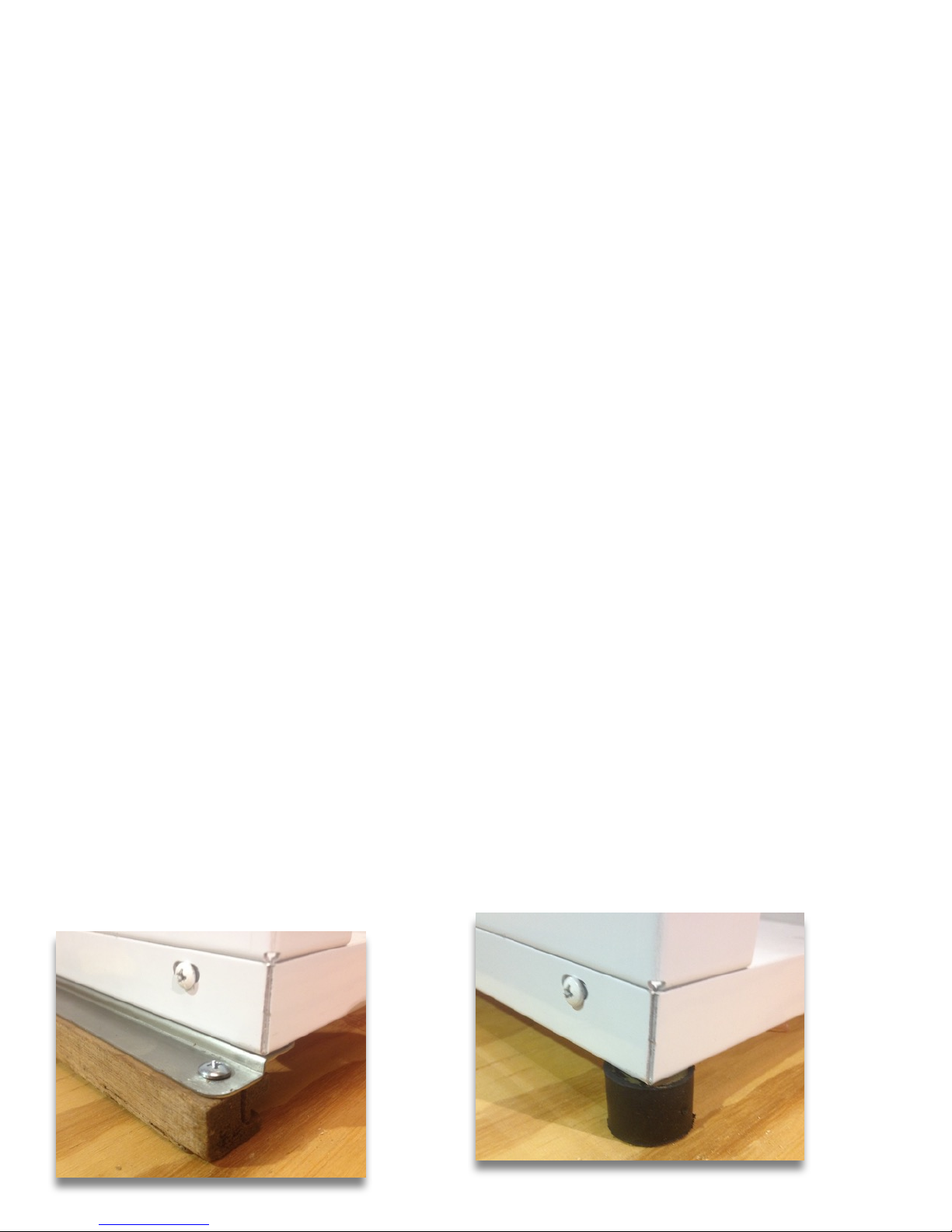
1. Mount the 2 brackets to the bottom of the unit on either side using the supplied 1/4” bolts.
Illustration 1.
2. Cut 2 - 3/4” thick spacers the length of the mounting bracket and locate under mounting brackets
to maintain 3/4” space under unit for combustion air to enter bottom.
3. Place unit and spacers into place to locate 4 mounting holes and mark their positions.
4. Remove the unit and drill the 4 pilot mounting holes in the mounting surface.
5. Screw or bolt unit and spacers into place.
NOTE: Optional mounting studs with rubber spacers can be use to mount the unit. Illustration 2.
These will provide the proper clearance under the heater for combustion air without the need to
cut spacers.
Illustration 1 Illustration 2
Page 3
Making Connections
1. Connect plumbing to water lines taking care to make correct “COLD” and “HOT” orientation.
2. Connect 3/8” FM flared LP gas line to 3/8” M flared gas fitting. Hand tighten initial connection to
assure it is not cross-threaded, then tighten with wrench while backing up fitting with a second
wrench. Note: This flare fitting is a “dry” fitting, meaning no pipe dope of tape should be used
when making the connection. The gas line should be an approved type of one, continuous,
unbroken line from the propane locker to the appliance.
3. Turn on the gas and check the water heater and all connections for gas leaks with a leak detecting
solution. Never use a flame to check for gas leaks.
4. Turn on water supply line and check for water leaks.
WARNING : NEVER install heater in a manner that is not vented to the outside. Doing so will void the
warranty and cause the heater to malfunction and could result in serious injury or death. Terminus of
flue outside boat should be above the water line.
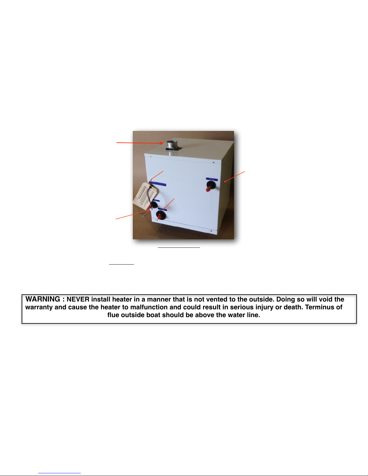
Flue Pipe Installation
Cold In
Hot Out
Gas Connection
12VDC
2” Flue pipe
Connection
After the unit is secured into place, the exhaust pipe is installed as follows:
1. Locate and install the flue terminus on the outside of the vessel. It must be mounted well above
the waterline, while keeping the flue pipe run under 10’. If PrecisionTemp’s optional mushroom
vent is used, it can be mounted on a vertical or horizontal surface. It must be located so that no
water can enter the flue system and no flue gasses can re-enter the living area through hatches
or other air intakes.
2. Carefully measure and cut one, continuous length of flex flue pipe to run from the 2” flue pipe on
the top of the appliance to the flue terminus. Keep length and bend of the pipe to a minimum.
2” stainless flex duct is recommended. Never use galvanized or CPVC pipe.
3. Now remove the pipe and coat the inside diameter of the flue pipe elbow with high temperature
silicone sealant or equivalent.
4. Attach either end of the flex pipe to the appliance outlet and the flue terminus. This can be done
with self-tapping screws or by pre-drilling the hole before inserting metal screws. At least two
screws must be used to secure the pipe.
NOTE: The appliance must be disconnected from the gas supply piping system
during any pressure testing of the system at test pressures in excess of ½ psi. The
appliance must be isolated from the gas piping system during any pressure testing at
test pressures equal to or less than ½ psi. Pressure inlet to valve, 13” W.C. maximum,
11” W.C. minimum. Pressure at outlet of valve is factory set at 10”. Burner manifold
pressure is W.C. 8.9” W.C. +/- .2” at tap on burner manifold.
Page 4
How to Operate
WIRING INSTRUCTIONS
The appliance, when installed, must be electrically grounded in accordance with local codes
or, in the absence of local codes, with the National Electrical Code, ANSI/NFPA 70 and/or the
CSA C22.1, Canadian Electrical Code.
It is required that the unit be connected through a switch or beaker that is connected directly to a
12V DC battery or to the filtered side of an AC/DC converter. Avoid unfiltered “linear” voltage
sources. Use a minimum of 18 gauge wire, UL and CSA Listed.
Never replace fuse with one rated over 5 amps.
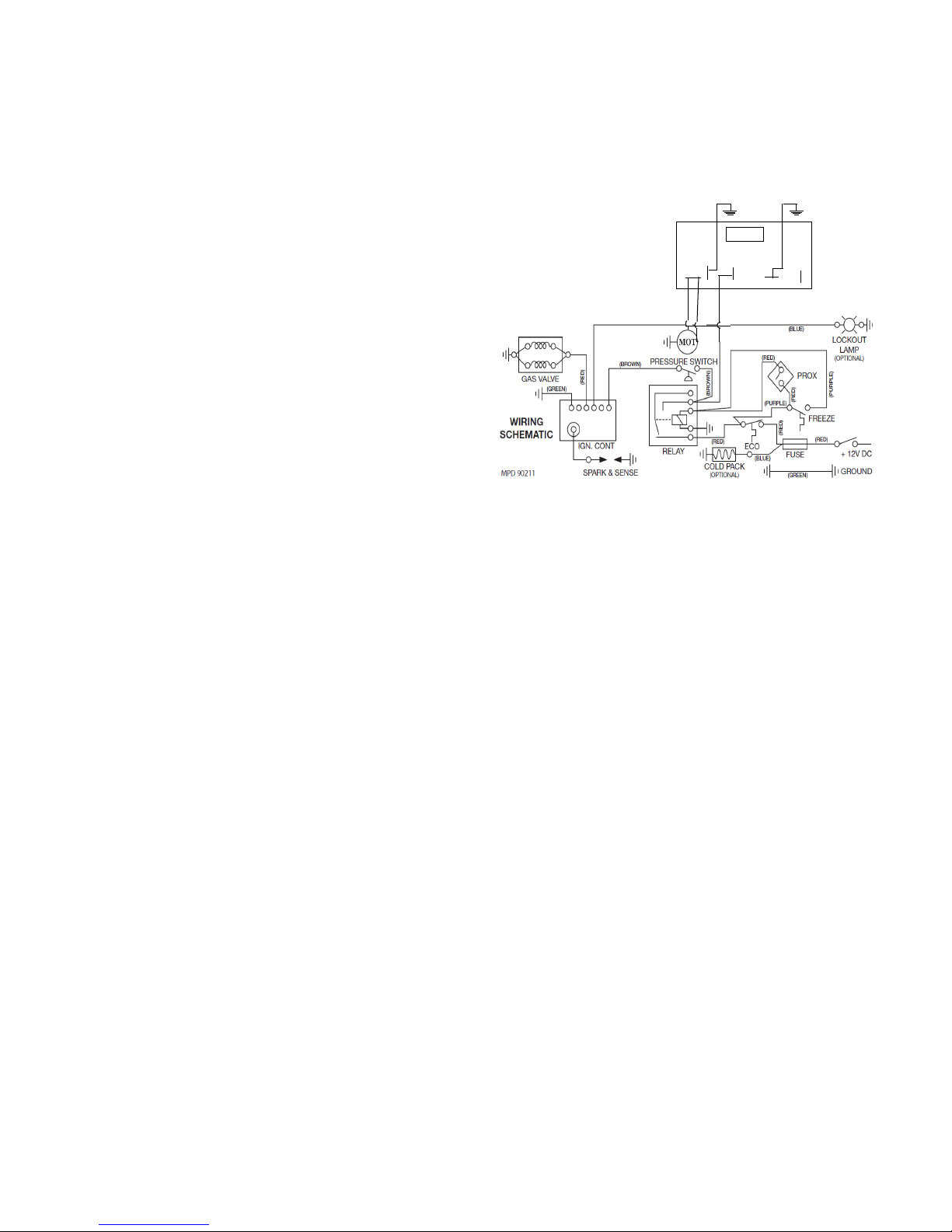
Refer to the Wiring Diagram. Install a remote switch in a
convenient location. Before making the
connections, turn the switch to the OFF position.
PRESSURE RELIEF VALVE
THIS VALVE IS A SAFETY COMPONENT AND MUST NOT BE REMOVED FOR ANY REASON OTHER
THAN REPLACEMENT. This water heater is equipped with a pressure relief valve that complies with the
standard for Relief Valves and Automatic Gas Shutoff Devices for Hot Water Systems, ANSI Z21.22 / CSA
4.4.
This valve protects against excessive water expansion only. This water heater has separate and
dedicated protection for excessive heat.
If you use a discharge line, do not use a reducing coupling or other restriction smaller than the outlet of
the relief valve. Allow complete drainage of both valve and line.
FOR REPLACEMENT PARTS:
•
DO NOT install anything less than a pressure relief valve certified by a nationally recognized
testing laboratory that maintains periodic inspection of product of listed equipment or materials, as
meeting requirements for Relief Valves and Automatic Gas Shutoff Devices of Hot Water Supply
Systems, ANSI Z21.22 / CSA 4.4. Valve must have maximum set pressure not to exceed 100 psi.
• Install replacement valve into opening provided and designated for this purpose on water heater.
• Installation must conform with local codes or in the absence of local codes, Standard on
Recreational Vehicles, ANSI A119.2 or CAN/CSA-Z240RV.
RED is 12V DC Positive power IN.
GREEN is 12V DC Ground
BLUE is 12V DC Pos. Lockout Lamp Signal
(See illustration of typical switch configuration)
RED
GREEN
BLUE
WIRING DIAGRAM
WIRING INSTRUCTIONS
The appliance, when installed, must be
electrically grounded in accordance with local
codes or, in the absence of local codes, with the
National Electrical Code, ANSI/NFPA 70 and/or
the CSA C22.1, Canadian Electrical Code.
It is required that the unit be connected through a switch that
is connected directly to a 12V DC battery or to the filtered
side of an AC/DC converter. Avoid unfiltered “linear”
voltage sources. Use a minimum of 18 gauge wire, UL and
CSA Listed.
Refer to the Wiring Diagram. Install a remote switch in a
convenient location. Position the wall plate with the letters
up. Before making the connections, turn the switch to the
OFF position.
M+M-+12V
GND
(Red)
(Green)
(White)
SW
VC12-18
GROUND
RED is 12V DC Positive power IN.
GREEN is 12V DC Ground
1) Pressurize the water system by turning on pump or city water pressure.
2) Purge all air from the system by turning on the faucets until a steady stream of water flows.
3) Turn on the 12V DC power supply.
4) Turn on the LP supply at the tank and the manual gas valve (if installed).The water heater will
remain dormant until a water tap is opened and the heater senses water flow of at least 0.5
GPM.
5) Turn on the hot water tap to full open. The heater will fire up and hot water will flow from the tap
in the time it takes to traverse the lines from the heater to the faucet. (If this is the first usage,
you may have to turn the water on and off several times to purge the LP gas lines of air. If the
heater fails to light, turn the power switch OFF, then ON to reset the ignition control. After
ignition, water flow can be reduced and cold water added as desired.
6) To shut off the water heater, shut off the water. Shut off power at remote switch or breaker.
7) Should overheating occur or the gas supply fail to shut off, turn off the “ON/OFF” power switch.
Page 5

Temperature Adjustment
Outlet water temperature can be adjusted by turning
the “Summer / Winter” up 1/4 turn. Full vertical is the
warmest position and full horizontal is the coolest
position.
“Summer / Winter” valve in “Summer” position
A Note About “Navy Showers”
It is recommended to take a shower just like you would at home. That is, leave the water running
through the entire shower. The hot water system is designed to deliver a continuous, comfortable
flow of hot water and that’s the way it works best.
Shutting off the shower with the shower head button wastes water. Each time this is done, the
shower head “trickles”, filling the hot water line with cold water. This cold water has to be purged
from the line each time the shower head is turned back on. Tests have shown that this will not
save water and sometimes uses more water than leaving the shower run continuously.
Winter Operation and Winterizing Water
If your heater is equipped with the optional Cold Weather Protection Kit, (CWP)it will prevent
freezing under most conditions. In order for it to function, 12 VOLT AND GAS SUPPLY MUST
REMAIN TURNED ON. This allows the burner to fire and electric elements to protect the system.
Any freezing of the water heater or other plumbing components can cause severe damage that is
not covered by warranty.
If your heater is not equipped with CWP, drain heater during freezing conditions as
follows:
1. Turn off water pump and the power and gas to the heater. Open the pressure relief valve by
lifting the handle to a 90° position from the normal position.
2. Summer / Winter valve should be turned to “SUMMER” position. See illustration.
3. Open at least one hot and cold water tap in the boat. This should drain the system.
Winterizing Procedure:
Before storing the system for the winter, the plumbing system must be winterized. This can be
done by either of the following methods:
1. Turn the Temperature adjustment knob to the full Summer (3 o’clock) and open the pressure
relief valve by lifting the handle to a 90° position from the normal position. All water should be
drained from the system. To do this, open one tap at a time using compressed air to purge the
system of all water.
2. Recommendations of your boat manufacturer should be followed. The water system can be
filled with RV, non-toxic anti-freeze. When you see the anti-freeze coming from the hot water tap,
the heater is protected.
Page 6
!
12346
5
8910111314171916
222018
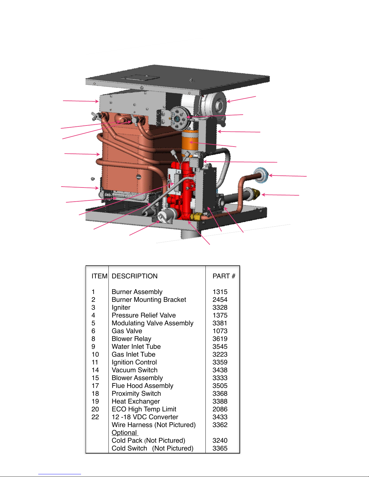
Exploded Parts View
Note: This Illustration Show Unit with Bottom Venting Rather Than Top
Venting. All Illustrated Components are Identical on Both Models.
ITEM DESCRIPTION PART #
1 Burner Assembly 1315
2 Burner Mounting Bracket 2454
3 Igniter 3328
4 Pressure Relief Valve 1375
5 Modulating Valve Assembly 3381
6 Gas Valve 1073
8 Blower Relay 3619
9 Water Inlet Tube 3545
10 Gas Inlet Tube 3223
11 Ignition Control 3359
14 Vacuum Switch 3438
15 Blower Assembly 3333
17 Flue Hood Assembly 3505
18 Proximity Switch 3368
19 Heat Exchanger 3388
20 ECO High Temp Limit 2086
22 12 -18 VDC Converter 3433
Wire Harness (Not Pictured) 3362
Optional
Cold Pack (Not Pictured) 3240
Cold Switch (Not Pictured) 3365
Page 7

TROUBLESHOOTING
Most problems are easily remedied by consulting
the trouble-shooting guide. If problems still persist,
contact PrecisionTemp for assistance. Only a
qualified technician should do any work involving
the gas system.
A periodic visual check of the burner flames should
be done by observing the flame through the “peep
hole” in the heat exchanger. There should be blue
flame with minimum or no yellow tipping. There
should be nothing obstructing the flow of
combustion and ventilation air.
Burner maintenance should be performed by a
PrecisionTemp Authorized Service Technician.
NOTE: The heater is dormant until it senses
water flow. When a water tap is turned on to at
least .5 GPM the burner will fire until water flow
is turned off and the heater again goes
dormant.
Heater Does Not Come On When The Water is
turned on. (Power vent not running)
1. Be sure power is on and panel breaker is not
tripped.
2. Check electrical contacts. Be sure the
connector is plugged into board. Using a
voltmeter, check for 12Volts on this connector.
3. Be sure all electrical connectors are secure
and the polarity is correct. (Red wire to positive
terminal).
4. Fuse in power wire might be blown. Replace
fuse.
5. Locate the ECO, high temperature switch (two
red wires) at the upper left hand of the heat
exchanger. Check for open circuit condition.
6. Be sure there is a battery in the system. Never
connect the heater directly to a power converter.
Some converters have circuits that are not pure
DC. This can cause malfunctions or damage to
the heater and is not covered by warranty.
7. Be sure that no water-mixing valve has been left
in the on position or using the shower head as a
shut off. This will permit water to bypass the water
heater and bleed cold water into the hot water
system. Always turn off both hot and cold water
valves after using.
There Is No Ignition When Water Is On (Power
vent is running)
1. Be sure the gas valve at the tank is “On”, there
is gas in the tank and the gas line is purged of all
air.
2. Be sure that flue terminus is not blocked
3. Check that the ignition wire is plugged into the
spark tower on the ignition control and is not
touching anything else.
4. Check flame site hole to see if igniter is sparking
from the probe to the burner. Bend ignition
wire to adjust to proper gap or contact
PrecisionTemp or your nearest authorized service
representative.
5. Check that there are no cuts or breaks in the
ignition wire. 6. Be sure that the power vent fan
has 12 volts to it when there is water flowing and
there are no obstructions in the flue pipe.
7. Safety vacuum switch may be out of
adjustment. Contact PrecisionTemp or your
nearest authorized service representative.
No Water Flows From Tap When Tap is Turned
on.
1. Be sure that water supply is turned on and that
there are no obstructions.
2. Hot and cold water lines connected to heater
are reversed. Correct by reversing their positions.
Burner Turns On But Temperature Fluctuates
Erratically.
1. May be caused by excessive restriction at the
water outlets, shower heads, aerators or water
strainers. These should be cleaned and any
shower head flow restrictor removed.
2. If temperature fluctuates as the pump cycles, a
pressure accumulator tank is needed in the water
system. If you have an accumulator tank, check to
see if it has become filled with water. If it has, drain
it so that it contains air only.
Heater Comes On But Rapidly Cycles On And
Off.
1. Water flow is too low. Increase flow at a tap.
Clean all aerators and shower head screens to
assure at least .5 GPM of water flow
2. Water pump is not functioning properly. Repair
or replace pump.
3. If the heater cycles as the pump cycles, a
pressure accumulator tank is needed in the water
system. If you have an accumulator tank, check to
see if it has become filled with water. If it has, drain
it so that it contains air only.
4. Air is in the water line. Bleed air by turning on all
water taps.
Page 8

Burner Ignites But Water Temperature Is too low
1. The water flow may be so high as to exceed the
capacity of the heater particularly if your supply
water is very cold. Slow the water flow.
2. The gas pressure may be too low. Be sure the
tanks are full and tank selector is not in center
position.
3. Check the dynamic gas pressure while the water is
on at full flow. The LPG pressure should be the
“manifold pressure” as shown on the specification
label while the heater is running. A gas-testing gauge
should be installed on the manifold tap so that it may
be read while heater is running. If it is too low, turn up
the gas regulator to the proper pressure. Regulator
may be defective and needs to be replaced. This
should only be done by a qualified technician.
4. The gas flow may be too low due to improper gas
line diameter (under 3/8 inch outside diameter). The
gas line may be excessively long (over 20-30 feet) or
the on/off solenoid at the tank (if you have one) may
have an orifice that is too small (under 3/16th of an
inch).
5. Check the heater air inlet openings and flue pipe
for airflow obstructions and clean.
6. Check that the “summer / winter” valve is in the
proper position for the temperature of the incoming
water.
Water Temperature Too Low at Lower Water Flow
Rates
1. Check that the “summer / winter” valve is in the
proper position for the temperature of the incoming
water.
2. Be sure to momentarily turn water flow to high,
then back to the lower flow when turning on a water
faucet. This will bring the gas flow to the required
higher setting.
Water Temperature Is Too Hot or No Temperature
Control.
1. Fuel tank regulator is set too high and manifold
pressure as described above Have the regulator
checked by a qualified technician.
2. Check that the “summer / winter” valve is in the
proper position for the temperature of the incoming
water.
3. Water flow too low for incoming water temperature.
Low Heat Rise and Excessive Water Flow Is
Required To Trigger Water Heater
If you find that your heater requires excessive flow to
activate it (much over .5 gallon per minute), it is likely
that you have cold water bleeding into the hot water
side of your water system.
1. Check that valves and faucets are closed when
not in use. If there is an on/off button on your shower
head, always turn the water valves off after the
shower to prevent cold water from bleeding into the
hot water system. This will keep the heater from
functioning properly.
2. Be sure that the bypass valve at the water plumbing
connections is in the "off" position. An open valve can
also permit water to bypass heater, causing it not to fire.
If any problem persists, contact an PrecisionTemp.
PrecisionTemp, Inc. WATER HEATER
LIMITED WARRANTY
PrecisionTemp, Inc warrants to the original owner and subject to the
below mentioned conditions, that this product will be free of defects in
material or workmanship for a period of two years from the original date of
purchase. PrecisionTemp’s liability hereunder is limited to the replacement of the
product, repair of the product, or replacement of the product with a reconditioned
product at the discretion of the manufacturer. This warranty is void if the product
has been damaged by accident, unreasonable use, neglect, tampering or other
causes not arising from defects in material workmanship.
This warranty extends to the original owner of the product only and is
subject to the following conditions:
1. For a period of two years from the date of purchase, PrecisionTemp will replace
the complete water heater if the heat exchanger leaks due to corrosion. This
warranty includes reasonable labor charges required to
replace the complete water heater.
2. For two years from the date of purchase, PrecisionTemp will repair or replace
any part defective in material or workmanship. This warranty includes reasonable
labor charges, required to remove and replace the part. Service calls to
customer’s location are not considered part of these
charges and are, therefore, the responsibility of the owner.
3. This warranty does not cover the following items classified as normal
maintenance:
a. adjustment of gas pressure
b. cleaning or replacement of burner orifices
c. cleaning or adjustment of burner assembly
d. cleaning or adjustment of flue
e. adjustment of pressure relief valve
4. In the event of a warranty claim, the owner must contact, in
advance, either an authorized PrecisionTemp Service Center or the
PrecisionTemp Service Department. Warranty claim service must be
performed at an authorized PrecisionTemp Service Center (a list will be
provided at no charge) or as approved, PrecisionTemp, Inc
11 Sunnybrook Dr. Cincinnati, OH 45237, 800-934-9690 Ext. 109. Return parts (or
water heater) must be shipped to PrecisionTemp “Prepaid”. The defective parts (or
water heater) become the property of PrecisionTemp and must be returned to the
Service Department,
PrecisionTemp, Inc. 11 Sunnybrook Dr. Cincinnati, OH 45237.
6. This warranty applies only if the unit is installed according to the installation
instructions provided and complies with local and state codes.
7. The warranty period on replacement parts (or water heater) is the
unused portion of the original warranty period or ninety (90) days,
whichever is greater.
8. Damage or failure resulting from misuse (including failure to seek proper repair
service), misapplication, alterations, water damage, or freezing are the owner’s
responsibility.
9. PrecisionTemp does not assume responsibility for any loss of use of vehicle,
loss of time, inconvenience, expense for gasoline, telephone, travel, lodging, loss
or damage to personal property or revenues. Some states do not allow the
exclusion or limitation of incidental or consequential damages, so the above
limitations or exclusions may not apply to you.
10. Any implied warranties are limited to two (2) years. Some states do not allow
limitations on how long an implied warranty lasts, so the above limitation may not
apply to you. This warranty gives you specific legal rights and you may also have
other rights which vary from state to state.
11. Replacement parts purchased outside of the original water heater warranty
carry a 90 day warranty. This includes the part at no charge.
This PrecisionTemp heater is designed for use in recreational vehicles, park
models, mobile food carts and marine applications for the purpose of heating water
as stated in the “data plate” attached to the water heater. Any other use, unless
authorized in writing by the PrecisionTemp Engineering Department, voids this
warranty.
11 Sunnybrook Drive
Cincinnati, OH. 45237
Phone: 513-641-4446 * 800-934-9690
Fax: 513-641-0733
www.precisiontemp.com
 Loading...