

Page 1
Controlled Laptop Charger Instruction Manual
Telephone: 02 6299 3477 ● Email: sales@3p-australia.com.au ● PO Box 6321 Queanbeyan East NSW 2620, Australia
www.3p-australia.com.au
Page 2
1
Telephone: 02 6299 3477 ● Email: sales@3p-australia.com.au ● PO Box 6321 Queanbeyan East NSW 2620, Australia
www.3p-australia.com.au
24/02/2011 V1.0
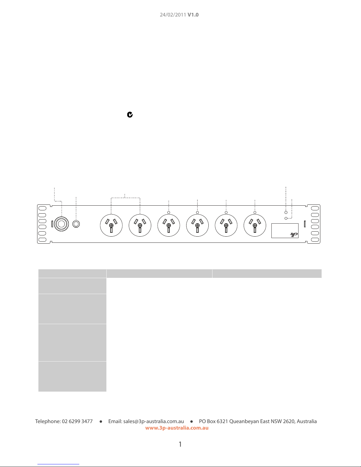
Power Lead
Circuit Breaker
Constantly Powered
Sockets
Controlled Sockets
Mode LED
Mode Button
1 2 3
4
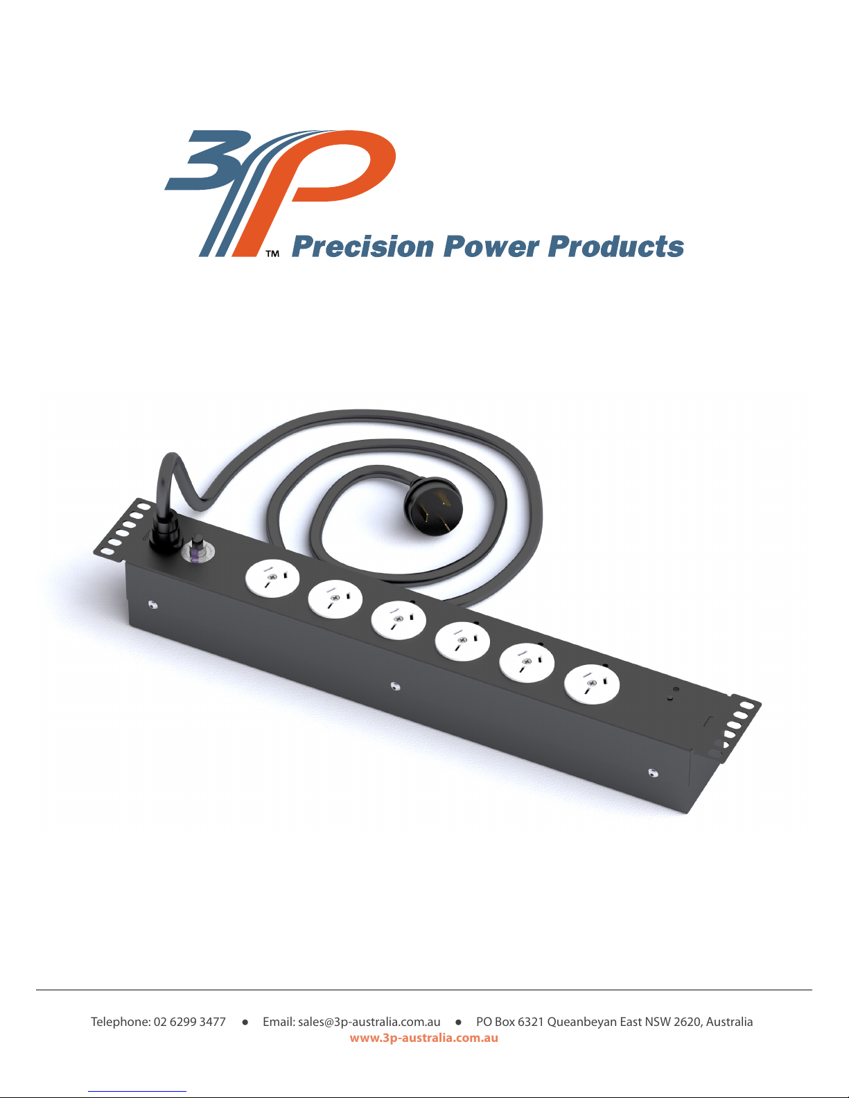
Controlled Laptop Charger
Part No: 800 - 410058
Current Rating: 10A
Voltage Rating: 230VAC 50 Hz
N28070
www.3p-australia.com.au
Specications
Model Number: 800-410058
Rating: 230 V AC @ 50Hz
Max Total Load: 10 Amps
Socket Rating 10 Amps
Mounting 19” mounting rails
Rack Space Requirement 1.5 RU
Conforms with AS/NZS 3197 in conjunction with AS/NZS 3100
C-Tick Compliant N28070
Sockets:
Constantly Powered: 2
Controlled: 4
Figure 1: Controlled Laptop Charger
Mode Description Mode Display
Disabled
All controlled sockets are off with power
only to the constantly powered sockets.
Mode LED flashes once every 4 seconds to
indicate unit power
Staged On
All sockets are enabled after staged
powering of controlled sockets 1-4, with
approximately a 1.5 second delay between
sockets
Mode LED is constant
Constant Cycle
The controlled sockets are cycled
continuously in order from socket 1 to 4.
Each socket will be powered for a period
of 1 hour before progressing to the next
socket.
The Mode LED will flash constantly, being on
and off for equal periods of half a second.
12h Cycle
Cycles through controlled sockets
powering each single socket for a period of
t hours once every 12 h cycle. Options of 1
or 2 hour periods.
The Mode LED will flash 1 to 2 times
followed by a 2 second pause. The number
of flashes corresponds to the time period
each socket is powered.
Table 1: Modes (For controlled sockets only)
Page 3

2
Telephone: 02 6299 3477 ● Email: sales@3p-australia.com.au ● PO Box 6321 Queanbeyan East NSW 2620, Australia
www.3p-australia.com.au
24/02/2011 V1.0
Application
The Controlled Laptop Charger is a purpose designed power management system providing both continuously
powered and controlled AC sockets. This design enables vital equipment such as cooling systems or switching
equipment to be powered from the same PDU (Power Distribution Unit) as controlled equipment such as laptop
power adaptors while providing energy savings through timer controlled cycles.
The Controlled Laptop Charger in designed with 4 modes; Disabled, Staged On, Constant Cycle and 12 hour
Cycle, allowing for usage in a wide range of applications. The Disabled mode provides a low power option only
powering critical equipment, while the Staged On mode reduces the peak inrush current reducing the
probability of tripping sensitive circuit breakers. The two cycle based modes provide significant power savings by
reducing the powered time of each controlled socket by up to 91.7% of that of a constantly powered socket.
Installation
The installation procedure for the Controlled Laptop Charger is as follows;
1. If rack mounting is desired, the Controlled Laptop Charger may be screwed directly onto 19” mounting rails using
two M6 screws and cages nuts on each side. Two mounting configurations are possible for the 1.5 RU power board.
Use either the top and lower central hole for a flush top fitting, or the bottom hole and upper central hole for a flush
bottom fitting.
2. Plug in but do not power the PDU’s power cord.
3. Plug in all appliances to be powered by the power board.
4. Finally power the PDU and set the mode according to requirements.
WARNING: If the supply cord is damaged, it should be replaced by a Precision Power Products agent to avoid
potential safety hazards.
Setting the PDU’s Mode
The mode button (as seen in Figure: 1) when pressed, cycles through the 4 available modes. Each time the mode
button is pressed the mode light will remain lit for 4 seconds during which the PDU will apply the new setting. Any
subsequent press will reset the delay timer. Once set you can identify which mode is in use according to the mode
LED sequence described in Table: 1.
Page 4

3
Telephone: 02 6299 3477 ● Email: sales@3p-australia.com.au ● PO Box 6321 Queanbeyan East NSW 2620, Australia
www.3p-australia.com.au
24/02/2011 V1.0
Mode 1: Sockets Disabled
During this mode each controlled socket will remain off.
Mode 2: Staged On
When changed to ‘Stage On’ or powering on the PDU whilst in this mode, the controlled sockets will
power on in series with an approximate 1.5 second delay. Once all sockets are on they will remain
powered.
Mode 3: Constant Cycle, 1 Hour period
Once set or powering on the PDU whilst in this mode, the PDU will cycle through each of the controlled
sockets sequentially providing power for a period of 1 hour. Once the 4th socket has completed its 1
hour period the cycle restarts.
Page 5

4
Telephone: 02 6299 3477 ● Email: sales@3p-australia.com.au ● PO Box 6321 Queanbeyan East NSW 2620, Australia
www.3p-australia.com.au
24/02/2011 V1.0
Mode 4: 12h Cycle, 1h periods
Once set or powering on the PDU whilst in this mode, the PDU will cycle through each of the controlled
sockets sequentially providing power for a period of 1 hour. Once the 4th socket has completed its 1
hour period all controlled sockets will remain unpowered for the remainder of the 12 hour cycle
(8 hours).
Mode 5: 12h Cycle, 2h period
This mode behaves the same as mode 4, however this mode powers each of the controlled socket for a
period of 2 hours therefore leaving the controlled sockets unpowered for the remainder of the 12 hour
cycle (4 hours).
 Loading...