

PrecisionLine RCR-PET Installation Instructions Manual
PrecisionLine RCR-PET
Dual Technology Motion Sensor
Installation Instructions
Description
PrecisionLine dual technology motion sensors combine
range-controlled radar (RCR) technology with a passive
infrared (PIR) system to increase false alarm immunity by
allowing them to sense human-sized objects within a specified range. Both the RCR and PIR systems must be triggered
to set off an alarm.
The sensor is designed to use a 12VDC power supply
provided by a UL Listed control panel.
Features
The sensor provides the following features:
• Pet Immune up to 80 lbs.
• Selectable range up to 35 feet (10.7m) - Internal jumper
allows radar range selection to optimize coverage.
• LED indicator - A multi-color LED provides detector
status.
• Opaque Fresnel lens - Blocks visible light.
Top View
(8.2m)
18’
(5.5m)
9’
(2.7m)
0’
9’
(2.7m)
18’
(5.5m)
Side View
7’
(2.1m)
0’
60°
30° 15°
Figure 2 - RCR and PIR Coverage Patterns
35’
(10.7m)
27’
27’
(8.2m)
35’
(10.7m)
90°
Radar
PIR
4°
floor line
Parts
The following parts are included with the sensor:
• RCR-PET sensor
• 1 screw to join the case halves
• 2 factory-installed jumpers
Selecting a Location for the Sensor
The sensor can be mounted in a corner or on a flat wall. Use
the following guidelines to determine the best location to
install the sensor:
• Mount the sensor so the expected movement of an
intruder is within a 90-degree radius in front of the sensor.
See Figure 2.
• Mount the sensor on a stable surface 7 to 8 feet (2.1 to
2.4m) high.
• DO NOT mount the sensor within 2 feet (0.6m) of metallic
objects.
• DO NOT place objects in front of the sensor that may
prevent a clear line of sight.
• Avoid locations that expose the sensor to possible false
alarm sources such as:
– Moving or vibrating objects (fans, pulleys, conveyor belts)
– Electronic fields (electric motors, high voltage equipment)
– Water spray or corrosive environments
– Heat sources (heaters, radiators) in the field of view
– W indows in the field of view
– Strong air drafts on the sensor (fans, air conditioners)
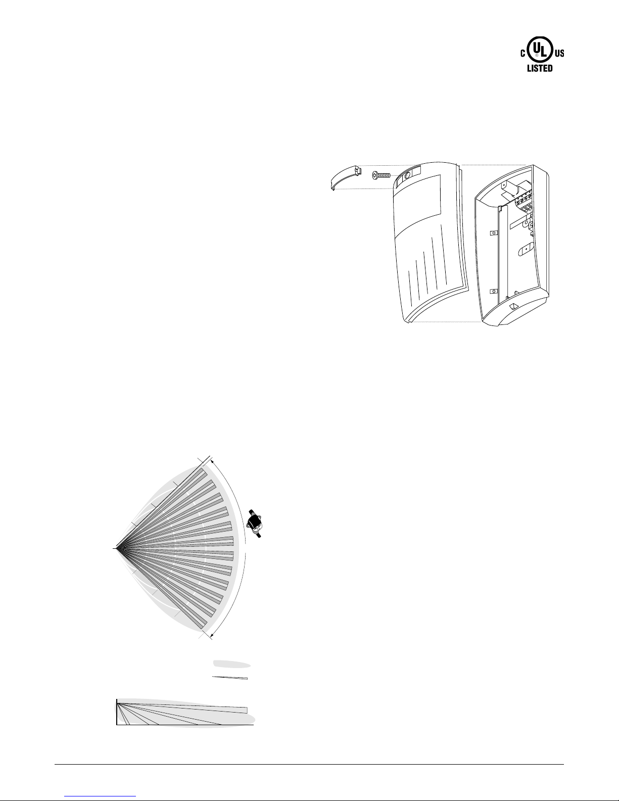
Figure 1. Sensor (exploded)
PrecisionLine RCR-PET
1

• When installing multiple sensors:
– DO NOT mount sensors facing each other .
– Mount them at least 20 feet (6.1m) apart.
– Mounting sensors back to back is not recommended, but
if an application requires such mounting, use the 9-foot
(2.7m) range, mount at least 1foot (0.3m) apart, and walk test
the installation to ensure proper operation.
Installing the Sensor
All wiring must conform to the National Electric Code (NEC)
and/or local codes having jurisdiction.
Important: DO NOT use this device for safety interlock
applications.
Use the following steps to install the sensor:
1. Run the security system wiring to the sensor location.
Cornermount
knockouts
Flat wallmount
knockout
Strain relief
Wiring
knockout
Terminal
sockets
Cornermount
knockouts
2 . Lift off the front cover/electronic module. Remove the
nameplate and loosen the screw if necessary. See
Figure 1.
CAUTION
Y ou must be fr ee of all static electricity before
handling sensor circuit boards. Touch a
grounded, bare metal surface before touching
circuit boards or wear a grounding strap.
3. If necessary, set the jumpers on the circuit board. See
Setting the Jumpers.
4 . Remove the appropriate wiring and mounting knock-
outs from the back cover. The sensor can be mounted
on a flat wall or in a corner. See Figure 3.
5. Pull the wires through the knockout holes and use the
two screws provided to attach the base to the wall. Use
screw anchors if necessary.
6 . Strip 1/4 inch (6.4 mm) of insulation from each wire.
7 . Run each wire through the strain relief and under the
appropriate screw terminals on the base and tighten
the screws. See Figure 3.
Flat wallmount
knockout
Figure 3. Sensor Base
8. Line up the tabs on the bottom of the cover/electronic
module with the corresponding tabs on bottom of the
base and snap the cover/electronic module firmly down
onto the base.
9 . Tighten the screw and replace the nameplate. See
Figure 1.
10 . Apply power . The LED should light green for approxi-
mately 25 seconds and then go out.
11. Walk test the coverage pattern as follows:
– Walk throughout the intended coverage area.
– Verify the sensor alarms. See Understanding the LED.
2
J2
J2 Range
Figure 4. Main Circuit Board
J3 LED
J3
PrecisionLine RCR-PET
Disable
 Loading...